Article

Customized Cost-Effective Cranioplasty for Large Asymmetrical Defects

1
Advanced Manufacturing Institute, King Saud University, Riyadh 11421, Saudi Arabia
2
Department of Oral and Maxillofacial Surgery, College of Dentistry and Dental University Hospital, King Saud University Medical City, Riyadh 11545, Saudi Arabia
3
Department of Mechanical Engineering, College of Engineering, King Saud University, Riyadh 11421, Saudi Arabia
*
Author to whom correspondence should be addressed.
Processes 2023, 11(6), 1760; https://doi.org/10.3390/pr11061760
Submission received: 13 April 2023 / Revised: 25 May 2023 / Accepted: 5 June 2023 / Published: 9 June 2023
(This article belongs to the Special Issue Computer-Aided Manufacturing Technologies in Mechanical Field)

Abstract

:
Cranioplasty or cranial reconstruction is always a challenging procedure even for experienced surgeons. In this study, two different design techniques for customized cranial prostheses are assessed for cranial reconstruction. Mirror reconstruction is one of the commonly used reconstruction techniques that fails when cranial defects cross the midline of symmetry. Hence, there is a need for a design technique for the reconstruction of cranial defects irrespective of their location on the symmetrical plane. The anatomical reconstruction technique demonstrates its applicability for a wide spectrum of complex skull defects irrespective of the defective position in the anatomical structure. The paper outlines a methodological procedure involving a multi-disciplinary approach involving physicians and engineers in the design and reconstruction of customized cranial implants for asymmetrical skull defects. The proposed methodology is based on five foundation pillars including the multi-disciplinary approach, implant design process, additive-manufactured implant, implant fitting analysis, and cost and time analysis for the customized implant. The patient’s computed tomography scan data are utilized to model a customized cranial implant, which is then fabricated using electron beam melting technology. The dimensional validation of the designed and fabricated titanium implant based on the anatomical approach results in a precision of 0.6345 mm, thus indicating a better fit than the standard mirroring method. The results of fitting accuracy also reveal that the manufactured implant’s average deviation is very close to the planned reconstruction area with an error less than 1 mm, suggesting that the customized titanium implant fits the skull model quite precisely. The cost and time analysis reports that the cost for producing a customized cranial implant using electron beam melting technology is around USD 217.5 and the time taken to build is approximately 14 h and 27 min, which is low when compared to other studies. The cost and time analysis also demonstrates that the proposed design would be less burdensome to patients when compared to standard practice. Therefore, the new anatomical design process can be used effectively and efficiently to treat a number of diverse cranial abnormalities with the enhanced cranial implant design.

1. Introduction

Restoration and reconstruction of cranial defects represents serious challenges to the patient, the surgeon, and society. Large cranial defects determine the outline of the facial appearance and one of the primary objectives in the reconstruction of cranial defects is to recover the brain function along with the restoration of facial appearance [1]. The large cranial defect is always a challenging surgery even for experienced surgeons due to the presence of vital organs such as the brain around the affected skull area [2]. In addition, the chances of infection, the uniqueness of each defect, and vital organs adjacent to the affected part increase the complexity of the cranioplasty. Cranial defects have various origins, namely tumors, congenital injuries, accidents, infections, etc. [3]. Skull defects often occur due to head traumas as well as skull deformities owing to a previous surgery or removal of a brain tumor, all of which needs a surgical operation to remove part of the cranial bone to access the brain [4]. To repair the damage, a synthetic substitute such as titanium or biocompatible polymer is used to replace the original bone structure that is too damaged to be re-used again.
Cranioplasty has a long history of surgical intervention, but the introduction of new techniques and implant materials has greatly improved the precise restoration of cranial defects. There are several methods for the reconstruction of cranial defects, keeping in mind a series of factors such as type of material used, surgical procedures, associated morbidity, and its healing time. Custom-designed cranial implants have gained importance over generic implants due to their custom fitting, shorter operating time, and better cosmetics [5]. The mirror reconstruction approach, which replaces the damaged component and mirrors it with the opposite side of a healthy part to create the implant geometry, is the most often used among the bespoke implant design methods [6]. If the defect is large and crosses the plane of symmetry—the midline, the mirror technique fails to generate the implant geometry. Hence, to overcome this limitation of the mirror reconstruction technique, an anatomical design reconstruction is proposed where it uses smooth guiding curves to generate the implant geometry.
Titanium and its alloys are regarded as excellent choices as bone substitutes due to their mechanically robust and bioactive characteristics [7]. Titanium and its alloys have the highest strength-to-weight ratio and high corrosion resistance among the other bio-metals [8]. In addition, the titanium alloy (Ti6Al4V) forms a thin protective film of titanium oxide on its surface, which helps in the osseointegration [9]. With the development of computer-aided design (CAD), computer-aided manufacturing (CAM), and modeling, as well as the advancement of prototyping technologies such as additive manufacturing (AM), the issue of cosmetic reconstruction has become less challenging. AM or three-dimensional (3D) printing is a new method for the fabrication of implants where successive layers of materials are placed on top of each other. AM allows the production of physical parts by obtaining the information directly from the 3D CAD model. This technology has gained widespread attention in medical applications due to its ability to produce a wide range of medical implants from the Computed Tomography (CT) Scanned data [10]. The emergence of 3D printing in medical applications with structural capabilities has been a useful tool in the preparation and planning of complex and challenging surgeries. AM technologies have been extensively used in many medical specialties including orthopedics, traumatology, craniofacial, and maxi-facial and plastic surgeries [11,12].
This research study focuses on the hypothesis that large cranial defects with asymmetric shapes can be precisely reconstructed and fabricated using anatomical design techniques and AM technology, respectively. The fitting accuracy analysis is also performed to make sure that the produced titanium cranial implant fits precisely onto the skull model. The objective of this study is to develop a methodology that can be used to produce a low-cost accurate cranial implant irrespective of the defective region either on a symmetrical or asymmetrical plane.

2. Materials and Methods

The methodology used in the reconstruction of a customized cranial implant as shown in Figure 1 involves various stages of a multi-disciplinary approach comprising the interaction between the physicians and engineers for the design as well as fabrication of the customized cranial implant. The communication interface contributes to the enhancement of implant design, reduction in clinical errors, and, most importantly, satisfaction to the patient. In this study, a clean skull model is selected for the creation of an artificial defect in the mid-cranial region. The clean skull is used to act as a reference model in the accurate assessment of the customized cranial implant. Two design reconstruction techniques such as mirror reconstruction and anatomical reconstruction are employed in the development of the customized cranial implant design. The obtained customized cranial implant design after reconstruction is assessed with the clean skull model for accuracy analysis. All experiments are performed in accordance with the guidelines and approval of the institutional review board committee (Project No. E-22-7235 and approval letter reference number 23/0012/IRB-A).

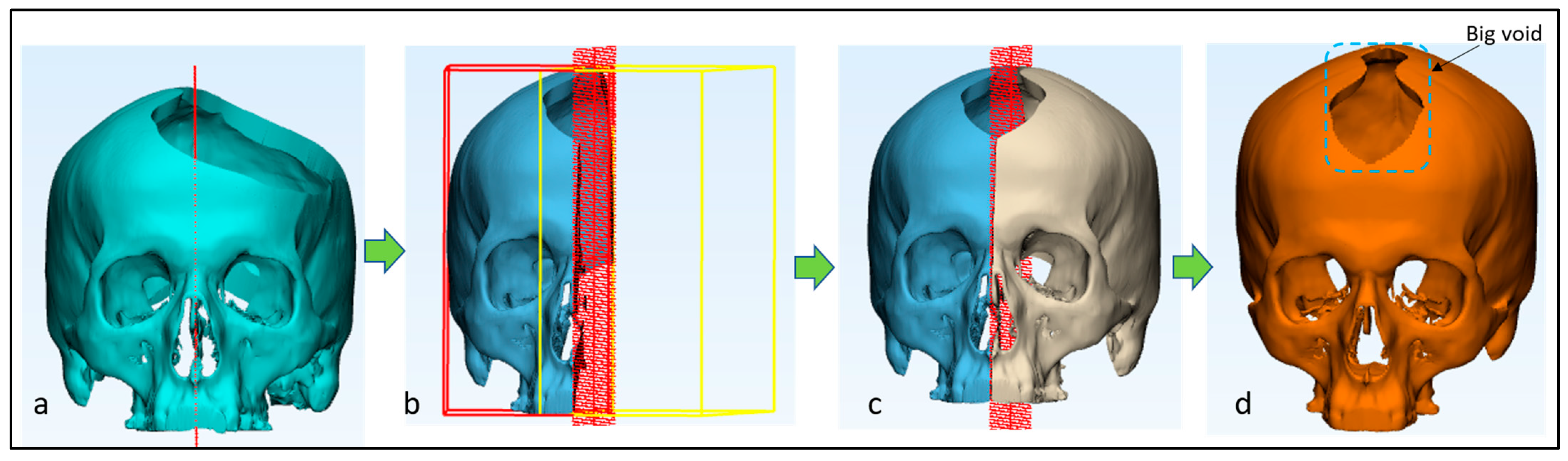
2.1. Image Processing and Creation of Artificial Defect

The radiologist performs the CT scan and the scanned images are recorded in the Digital Imaging and Communications in Medicine (DICOM) format, a standard way to save medical images. The DICOM files containing a series of two-dimensional (2D) images are stored in a database and shared with the design engineers. The DICOM images are processed using Medical modeling software MimicsR 17.0 (Materialise, Leuven, Belgium) and a 3D digital image (Figure 2a) is generated. The obtained 3D image is reconstructed and segregated into different segments (Figure 2b) using segmentation and region growing techniques in order to achieve the region of interest—skull (Figure 2c). The outer region of the healthy skull model is marked for the creation of an artificial segmental defect (Figure 2d) to replicate the characteristics of a defective skull region. This is performed to design a customized implant based on the defective region and then to compare the reconstructed designed skull implant with the healthy skull. The defective skull as shown in Figure 2e would act as a template for the customized implant design.

2.2. Skull and Implant Design
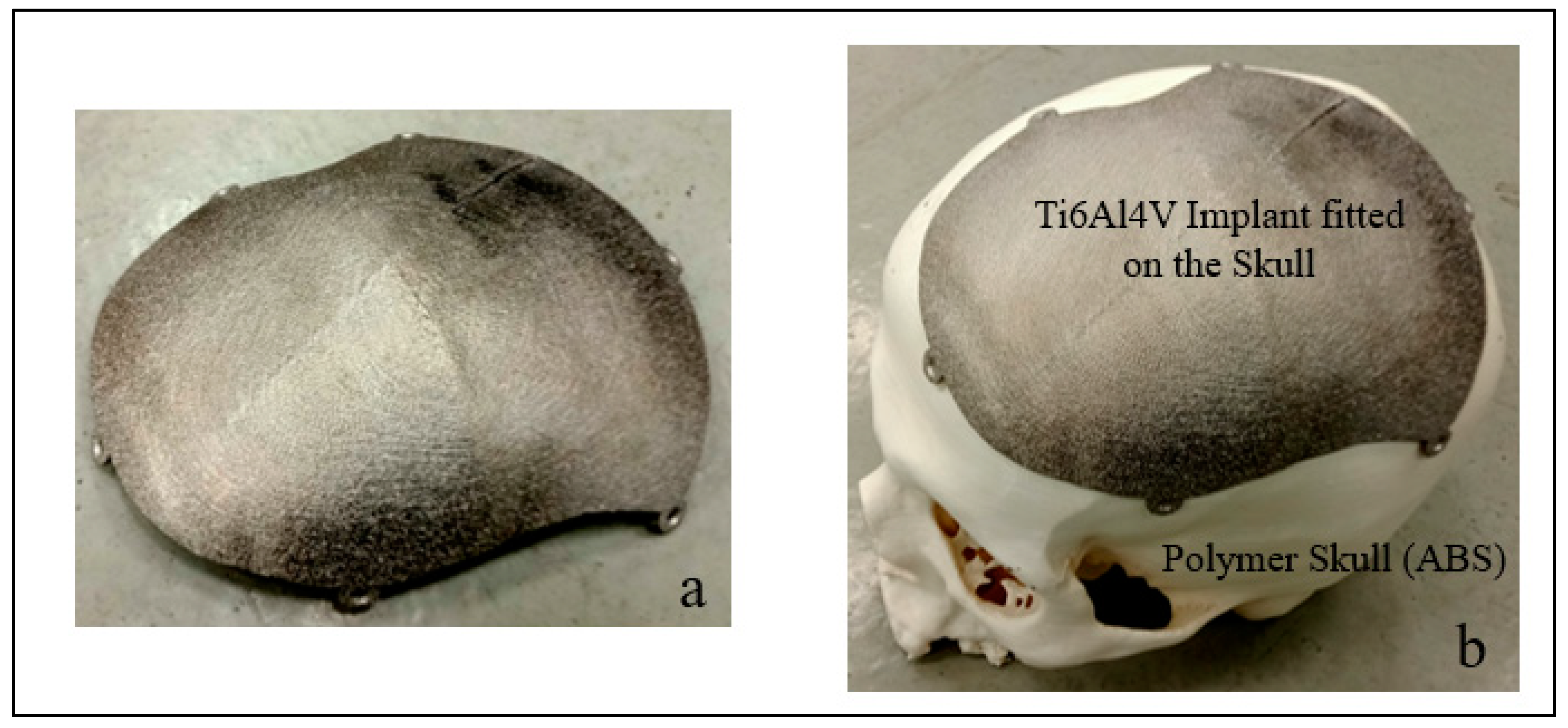
There are two well-known reconstructive techniques for implant design, which include the mirror reconstruction technique and the other anatomical design technique. The mirror technique is the most applied reconstruction technique in cranial implant designs [13,14]. There are several research studies involving mirroring techniques in the reconstruction of cranial defects [15,16]. In this technique, the defective part is removed and the healthy unaffected part is mirrored based on the referenced symmetrical plane in order to obtain a clean and healthy skull model. Based on the healthy skull model, the customized implant is designed.
In this study, the mirror reconstruction technique is employed initially to generate the implant model owing to its simplicity. The purpose is to evaluate its feasibility for the asymmetrical defect that is being investigated in this research. Thus, the experimental cranial segmental defect is subjected to the mirror reconstruction technique using medical modeling design software 3-Matic 13.0 (Materialise, Leuven, Belgium). A mid-plane is defined (Figure 3a) by choosing two extreme end points after importing the segmental defect into 3-Matic. Based on the mid-plane, the left side of the tumor region is resected in order to perform the mirror operation (Figure 3b). The healthy right side of the cranial region is mirrored to the left side (Figure 3c) as well as merged and wrapped to obtain the final skull (Figure 3d). However, the obtained final skull still has voids, so the model cannot be used for implant design. If the cranial defect crosses the plane of symmetry, it is impractical and inaccurate to use the mirror reconstruction technique. Therefore, there is a greater need of an alternative approach for asymmetrical anatomical defects.
One of the major drawbacks of the mirror reconstruction technique is that it can only be used for unilateral defects and not in every defective case study. If the defect is large and is located on both sides of the symmetrical region, the design fails. Hence, to overcome this error, a new design technique known as anatomical reconstruction is used.
In anatomical reconstruction design, a guiding curve is used for the bone reconstruction. It is a curve-based surface processing and refinement process. The experimental segmental defect is imported into 3-Matic (Figure 4a) and a smooth curve is chosen with “attract and attach curve” to mark around the defective region as an outline of the defect (Figure 4b). The next step of creating the sketch plane based on the mid-plane method is optional as it is employed with the unilateral defect to project the mirror image of a healthy skull along the midsagittal plane, which serves as a template (Figure 4c).
As in the present case, the defect is on the bilateral region, where mirroring is inapplicable. Hence, the damaged cranium outlines and reference data are imported into the sketch plane, which is then rotated at 90° (Figure 4d,e), resulting in an overlay that provides an estimation of the starting and ending points of the spline. Following that, each spline is manually drawn on the outside bone surface using the reference geometry (Figure 4f).
Refinement of the guiding curve is performed to match the skull model (Figure 4g). An experienced individual is required to execute this task, given that the splines serve as the fundamental geometry for generating a simulated cranial implant. A surface reconstruction operation is used to obtain the resulting implant surface with the entity as a smooth curve drawn around the defect and the guiding lines as the sketch plane. The implant template is provided with a bone thickness of 1 mm via the uniform offset tool, thus transforming it into a preliminary virtual implant (Figure 4h,i). The removal of undercuts and the creation of screw holes, followed by the implementation of smoothing and finishing procedures (Figure 4j,k), are carried out to ensure a precise fit of the implant onto the affected area of the skull (Figure 4l). At the initial revision meeting, the surgeon and the design engineers examine and validate the design model as shown by the red circle (Figure 1).

2.3. Fabrication

AM enables the fabrication of models directly from the 3D virtual model, thus reducing the cost and time. In this study, a Stratasys Dimension Elite Fused deposition modeling (FDM) 3D printer is used for the fabrication of the cranial polymer model and ARCAM’s Electron beam melting (EBM) machine is used for the fabrication of the titanium cranial implant. ARCAM’s EBM technology is regarded as the state-of-the-art metallic system, which rapidly manufactures custom-designed objects based on the CT data. The fabrication of medical implants using EBM is extremely beneficial as the whole process takes place in a closed environment with an elevated temperature of 700 °C to reduce the build-up of residual stresses and other impurities. EBM has been extensively used for orthopedic medical devices including knee, hip, cranial, dental, and maxillofacial implants.
The cranial model is produced using Acrylonitrile butadiene styrene (ABS) material through the FDM machine (Figure 5a). Supports are required to assist the overhang parts during the build process. The final obtained cranial model with supports (Figure 5b) is subjected to a soluble solution of heated water and cleaning agent to remove the supports (Figure 5c).
For the implant fabrication, 3D data of the customized implant design are imported into the EBM machine where the high-velocity beam of electrons bombards and melts the Ti6AL4V ELI powder as per the geometry under vacuum conditions. To prevent the dispersion and interaction of electrons with air particles, the entire EBM process is carried out in an enhanced vacuum of 10−3 to 10−5 mbar. To reduce the vacuum pressure during melting, helium gas is released, allowing the component to cool and ensuring beam consistency [17]. Depending on the design target, the beam current and scan speed changes. Thin wall features are melted at a beam current of 5–10 mA, whereas larger sections are melted at a beam current of 20–30 mA. In this study, titanium alloy powder (Ti6Al4V ELI) with particles between 50 and 100 µm is used. The chemical composition of Ti6Al4V ELI (extra-low interstitial) consists of 6.04% Al (Aluminum), 4.05% V (Vanadium), 0.013% C (carbon), 0.0107% Fe (Iron), and 0.13% O (Oxygen), with the rest as Ti (Titanium) in weight percent.
The schematic diagram of the EBM fabrication process is illustrated in Figure 6. The EBM mechanism comprises four stages.
  • Preheating/sintering the powder;
  • Melting with focused electron beam;
  • Lowering the build platform;
  • Raking the powder.
Stage 1: The titanium powder is initially preheated at a faster scan speed until it reaches a target temperature of 730 °C. In this stage, the default ARCAM parameters of preheat I and preheat II are preferred. In preheat I, the entire powder bed is scanned, while in preheat II, the scanning is primarily performed in the building region.
Stage 2: The high-speed electron beam scans the metal powder line by line in accordance with the CAD design. Melting comprises two cycles, contouring and infill hatching. Initially, numerous electron beams melt the contours as per the boundary cross-section of the 2D slices. Infill hatching consists of melting within the contours with the beam rastered back and forth. Most of the melting is performed during hatching, and the remaining powder is eventually recycled and used again in the next build.
Stage 3: The build platform is lowered by a predetermined height following each melt cycle.
Stage 4: The build platform is lowered, a fresh layer of powder is evenly raked on top of the previous build layer, and the same process is repeated to complete the build cycle.
The obtained built titanium cranial implant is subjected to a powder recovery system (PRS) (Figure 7a) for post-processing to blast away the semi-sintered powder particles (Figure 7b) attached to the implant. The blasting is performed with high-pressure air mixed with Ti6Al4V powder. The blasted titanium powder is recycled back to the EBM machine after passing through the sieving machine. The titanium implant with supports (Figure 7c,d) is manually removed using tools such as plyers. The obtained titanium cranial implant without supports (Figure 7e) and the ABS cranial model are evaluated through fitting analysis in the second revision meeting between the surgeons and the fabrication engineers.
The customized titanium cranial implant is then subjected to the cleaning and sterilization process to reduce contamination and to destroy all microbes before being prepared for surgery. Following the fabrication process, material characterization of the titanium implant as well as the cost and time analysis study are also carried out. The material characterization involving the powder metallurgical test and elemental analysis of the build specimen is performed to investigate the chemical composition of feedstock powder and the material composition of the Ti6Al4V ELI specimen post EBM fabrication. Cost and fabrication time analysis is performed to understand the economics of the customized cranial implant.
Scanning electron microscopy (SEM) analysis is carried out to investigate the titanium powder size morphology used in the EBM process. Ti6Al4V ELI gas-atomized powder produced by ARCAM is used to create the EBM-built cranial implant in this investigation. The ELI variant of Ti6Al4V comprises lower amounts of oxygen, nitrogen, carbon, and iron. Figure 8 illustrates the SEM images of Ti6Al4V powder particles. The Ti6Al4V ELI powder used in the ARCAM’s EBM machine confirms that the powder particles are predominantly spherical in shape with a slight variation in the geometry.
In the EBM process, fine powder particles between 50 and 100 m are employed. The size and shape of the powder have an impact on the EBM build platform and its sintering kinetics between the powder particles. The geometrical dimension of the feedstock powder is determined to be in the range of 50 to 100 µm with an average estimate of 75 µm using a laser diffraction technique. The chemical composition (wt%) of Ti6Al4V ELI powder used in the fabrication process is in accordance with the ASTM F136 Standards, as shown in Table 1.
The Ti6Al4V ELI post-EBM-manufacturing material composition is examined and the overall composition of the specimen is measured as follows: 6.24% Al, 3.89% V, and 89.87% Ti in weight percent. The chemical composition of the manufactured EBM specimen has not deviated significantly from the initial composition of the powder feedstock, as provided by ARCAM’s EBM.

2.4. EBM-Built Cranial Implant Cost and Time Analysis

The economics of EBM fabrication of the cranial implant are examined here. Because of the significant investment costs associated with the product development phases in the medical industry, accurate cost assessment of AM parts is crucial. Furthermore, incorrect estimates have costly repercussions and may lead to output loss. Few AM cost models have been developed by previous researchers [20,21]. When compared to the traditional manufacturing process, the EBM process depends on a number of selective factors in the production cycle [22]. The AM cost varies with respect to the manufacturing technology, design geometry, orientation, and the type of material used [23]. This work makes use of an inclusive cost and time model developed by Priarone et al. [24], to investigate the economics of the EBM-fabricated cranial implant. The weighing scale (Ohaus Company, Parsippany, NJ, USA) is used to determine the weights (in grams) for the cranial implant, as shown in Figure 9.
The implemented cost model to estimate the fabrication cost (C EBM Build Part) of the cranial implant (Table 2) involves the raw material cost, energy consumption cost, and the machine running cost as presented in Equation (1). As shown in Equation (2), the raw material cost is composed of the price and the consumption of material for each build, whereas the energy consumption cost is associated with the cost of running the EBM machine while fabricating the cranial implant. The machine running cost includes the EBM run time cost, which includes the EBM ownership cost and its consumables. Among all, the AM machine running cost constitutes a substantial portion of the fabrication cost; however, these costs gradually decline over time [25]. The cost model for the EBM-fabricated cranial implant is defined as follows:
CEBM Build Part = Raw material cost + Energy consumption cost + machine running cost
CEBM Build Part = (RMCost × MConsumpition) + (ECost × FTime) + (Mcost × FTime)
RMcost = Raw material cost (USD/gram)
Mconsumpitio = Material consumption (grams)
FTime = Fabrication time of build part and Post-processing measured in hh:mm and simplified in hours for multiplication
ECost = Energy consumption cost measured as electricity cost in USD/KWh.
Mcost = Machine running cost in USD/hr.
Prosthesis fabrication is often expensive and requires complex intraoperative procedures. Several researchers have reported the cost of manually shaped and custom-shaped titanium cranial implants in prior studies. The average cost for the manually shaped titanium cranial implant is CAD 18,335 ± CAD 10,265, whereas, for the customized patient-specific implant, it is CAD 31,956 ± CAD 31,206 [28]. One of the factors that contribute to the rising cranial implant cost is the long duration of stay in the hospital post operation. A previous study of 8275 cranioplasty patients found that the implant material does not affect the complication and cost rates, but rather the size of the defect, the timing of the cranioplasty, and any prior infections [29]. A customized titanium implant costs approximately USD 5500 to USD 8000 depending on the size and complexity [30]. Abel de la pena et al. in their study proposed a customized cranial prosthesis including the digital design and 3D printing with a cost estimate of about USD 600 [31]. Manrique et al. [32] in their study indicated that the average cost and manufacturing time for a craniofacial implant were USD 8493 ± USD 837 and 2 weeks, respectively.
The time analysis for the fabrication of the cranial implant in this study includes the time taken for the processing of CT scan images (TImage processing), the implant design process (TImplant Design), fabrication of the cranial implant (TFabrication), and the post-processing (TPost-processing) of the implant. The time taken for post-processing is measured in hh:mm.
TAnalysis = [TImage processing + TImplant Design + TFabrication + TPost-processing]
The time analysis (TAnalysis) for the fabrication of the cranial implant is presented in Equation (3). The time taken for the processing of CT scan images is approximately 0:30 min and for designing the implant is around 1:30 min. The EBM fabrication time for the cranial implant is approximately 11:20 h, as explained in Table 2. The post-processing time for the removal of supports is around 1 h to 1:15 min. On average, it takes around 1 h:07 min for the removal of supports.
TAnalysis = [ 0:30 + 1:30 + 11:20 + 1:07] hh:mm
TAnalysis = 14:27 hh:mm

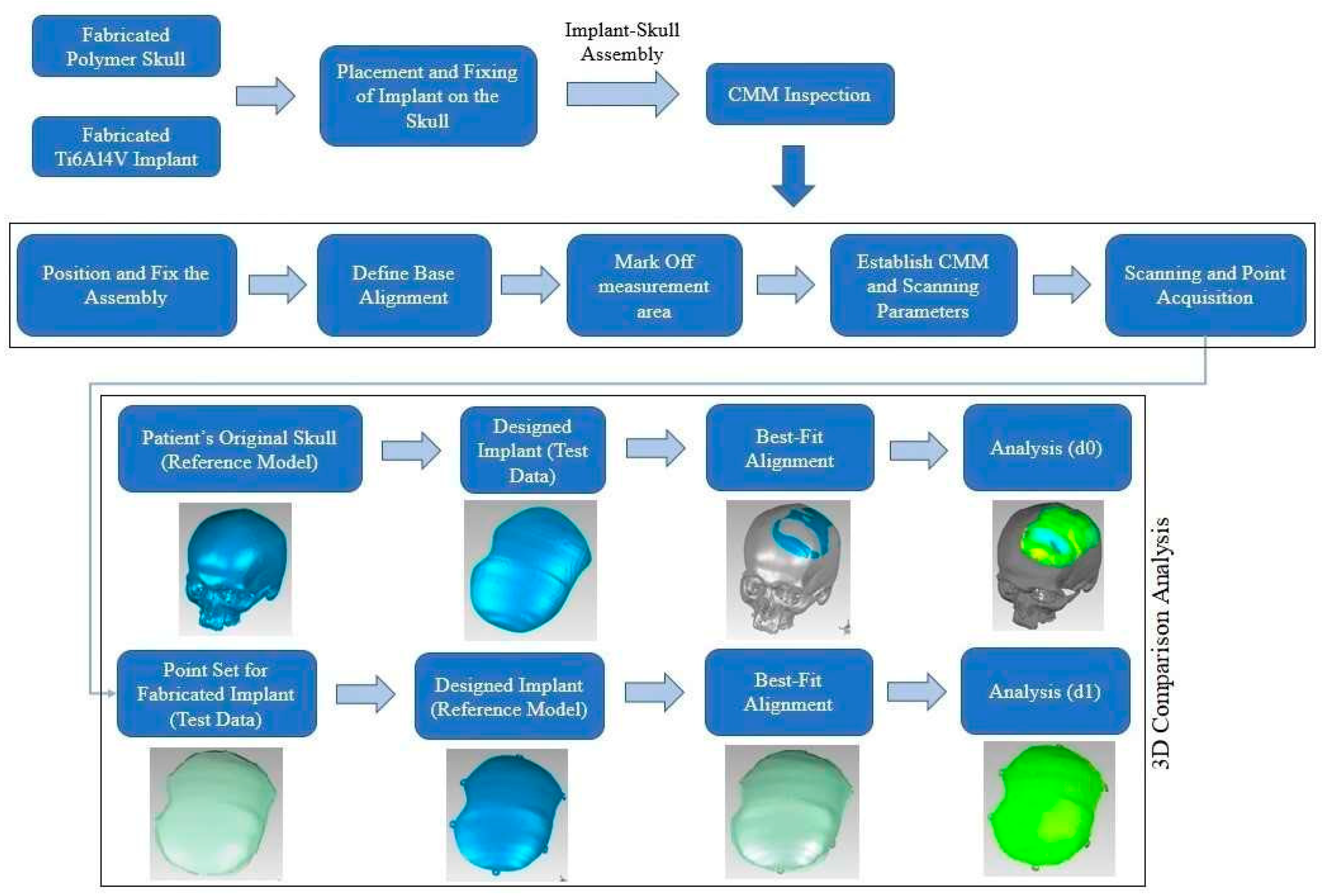
2.5. Implant Accuracy Evaluation

The mechanism for evaluating accuracy is shown in Figure 10. In this study, ABS, a typical thermoplastic material, is used to make the skull framework. The EBM titanium implant is subsequently assembled on the ABS skull framework for accuracy fitting assessment, as shown in Figure 11a,b.
A set of three EBM implant replicas is manufactured and each implant is examined three times on the Coordinate Measuring Machine (CMM), as illustrated in Figure 12a. The three prototypes are produced and measured three times to accommodate for any uncertainties that may have occurred during the fabrication or inspection process. The quality of models generated by the same machine can often fluctuate due to unpredictable influencing variables such as varied operator performance, environmental variables, and interferences. The three replicate EBM models are simply used to increase the result’s dependability. The purpose of a CMM inspection is to assess the fitting accuracy of an EBM-fabricated cranial implant and to determine any departure from the reference skull geometry.
A bridge-type CMM with a scanning touch probe (ACCURA, Zeiss, Oberkochen, Germany) is deployed. The scanning touch probe is employed, which has a 3 mm ball tip and a 50 mm overall length. This machine, as indicated in Figure 12a, can handle workpieces up to 1200 × 900 × 700 mm in size. The surface of the implant is analyzed after it is fitted to the skull, as shown in Figure 12b. The inspection points are collected on the implant to determine the maximum deviation in the outside direction. Cleaning the machine and probing system, configuring the part on the machine table, calibrating the scanning probe leading up to recording the points on the fabricated implant according to the guidelines prescribed by CMM manufacturers, as well as validating international norms, and establishing scanning parameters in the measurement software are all important stages when scanning the surface. It is crucial that the machine is clean and the measuring component is immaculately secured on the machine table. This is because dust and even the tiniest movement of the measurand can have a major impact on the accuracy of the inspection result. The coordinate system is established on the implant-skull assembly once it is perfectly positioned on the machine table. It specifies the assembly’s zero coordinate (0, 0, 0), which serves as a reference for acquiring points on the measurand. Scanning parameters include the point distance, which is curvature-dependent, having considered the implant form; a meandering scanning path to reduce the scanning time; varying combinations of distance between scanning lines and distances between points (0.5 and 1.5 mm, 1 and 0.5 mm, 0.75 and 0.5 mm, and 0.5 and 0.5 mm); a scanning speed of 10 mm/s (default value); and a scanning lines angle of 45°. The multiple pairings of distance between scanning lines and distance between scanning points are applied to incorporate any uncertainty due to the number of points and point distribution in the measurement outcome. The last step is to define the scanning area, as demonstrated in Figure 12c,d. Following the definition of the scanning region, scanning begins, and the associated points are gathered, as illustrated in Figure 12e.
The 3D comparison strategy is applied to interpret the point data obtained with the CMM. The 3D comparison is one of the most credible and thorough methodologies for viewing the surface variations between the test (restored) objects and the reference CAD model [33]. It is regarded as one of the most comprehensive and cost-effective techniques for detecting inaccuracies and depicting surface discrepancies [34]. A specific Geomagics Control software (Version 2014, 3D Systems Inc., Cary, NC, USA) with a 3D comparison module is chosen [35,36].
The surface-to-surface distance between the analyzing surface and the comparable reference surface is interpreted by the 3D comparison approach [37]. The outer surface of the implant is imported into the Geomagics Control as a test model and compared to the reference models in the two steps. The outer surface of the implant is imported as a point cloud in Geomagics Control® and set as a test model. The outer surface (test data) of the implant is investigated since the customized cranial implant is produced based on the outside shape of the skull. The classification of the test object and the reference CAD model is the first step in the 3D comparison study. The designed implant (test data) is compared to the reference CAD model, which is an original skull, in the first phase, and the modeling error is quantified as d0. The point cloud data of the produced implant (test data) are compared to the designed implant (reference) in the second phase to quantify the fabrication error, d1. The best fit alignment technique is used to synchronize the test data with the reference CAD model in both phases. The best-fit alignment approach is applied to ensure that the test and reference items are in the same coordinate system. The average deviation in the positive direction is considered to measure the errors (d0 and d1). The average deviation statistic is preferred because it approximates the spacing between the remodeled skull (or the customized implant) and the original skull by indicating the average deviation in an outward direction. The cumulative error is calculated by summing the errors (d0 and d1). This also gives insight about the implant’s overall fit.

3. Results and Discussion

Cranial reconstruction is always a challenging procedure, especially when the defects affect the facial skull symmetry, crosses the mid-line symmetry, and are irregular in shape. With the integration of modern imaging, computer-aided design with additive manufacturing have made it possible to design complex anatomical structures with precise accuracy, which was not previously possible through traditional means.
In this study, a multi-disciplinary approach is proposed to reconstruct large cranial defects with a customized implant design and precision-fitting and restoring the aesthetics. The CT scan images of the patient’s skull are processed using medical modeling software to retrieve the 3D anatomical model. The anatomical design technique and mirror reconstruction technique are used to generate the implant model based on the geometrical skull model. The mirror reconstruction model fails in generating the implant model as it is feasible only in symmetrical regions. Subsequently, the anatomical design technique is used in the design of the customized implant and fabricated using AM techniques involving FDM and EBM technologies. The anatomical reconstruction technique can be used for both symmetrical and asymmetrical regions as the defects crossing the midline are not an issue, due to its curve-based approach. The FDM-produced polymer skull model and the EBM-produced titanium cranial implant are subject to fitting accuracy analysis. The 3D-printed model provides a better understanding of the complex anatomy and pathology of the patient’s structure, which helps the surgeon in clinical practice and helps to make a more feasible plan for surgical operation. The 3D-printed medical models also decrease the operation time and reduce the surgical potential complications [38].
Based on the cost and time analysis, it is observed that the cost of fabricating a customized cranial implant is around USD 217.50 and the time taken for building the customized cranial implant is approximately 14 h and 27 min. The average time for building a customized cranial implant is less than a day when compared to the minimal possible time for industry-printed cranial models, which is 120 h (5 days) from the order of placement [39].
Lower fabrication timeframes demonstrate the development of user-friendly fast prototyping tools and emphasize the ability of producing patient-specific prostheses quickly. In contrast to other standard procedures, patient-specific cranial implants enable precise and anatomical reconstruction in a faster operating time. The complexity of the anatomical model and the operator’s skills may also have a significant impact on the implant’s build time.
The findings of 3D comparison analysis for a healthy skull and the designed implant models, as well as the designed and manufactured implant configurations, are shown in Figure 13a,b. Table 3 presents the findings of the fitting and accuracy analysis. The modeling approach (d0) has an accuracy of 0.0732 mm, indicating that the anatomical design approach utilized is highly effective; however, it might be improved with more expertise and experience. Furthermore, as demonstrated by the outer-direction deviation, the fabrication accuracy (d1) is predicted to be 0.5613 mm. The suggested implant design (encompassing both d0 and d1) has an overall precision of 0.6345 mm, which is more precise and results in a superior fit compared to the cranial implant obtained through the mirroring technique, which had an overall variation of 0.9294–1.31 mm [40,41,42]. The implant’s overall deviation is less than 1 mm of the targeted skull reconstruction area, thus confirming its proper fitting and positioning over the orbital skull region. The proposed methodology shows a higher accuracy with lower error margins for skull reconstruction, which is consistent in comparison to other cranial surgical procedures [43,44]. Through this study, it is intended to evaluate the accuracy and the applicability of the proposed customized design for large cranial implants.
It is difficult to determine the accuracy of the implant in reference to the original physical skull in a real-world situation. However, the surgeons are always uncertain of whether an AM-produced bespoke implant offers a suitable fit. Since a real physical model is not available, it is difficult to establish the fitting accuracy of the AM-built customized implant. As a result, this study has been conducted, which has established a procedure to assess the implant’s fitting accuracy. In this work, the research team created the defect on the healthy skull so that the two can be compared. The objective of this fitting accuracy investigation is to give a quantifiable measure of the fitting accuracy that can be anticipated from an AM-fabricated implant. For example, according to the present study, an inaccuracy of around 0.6345 mm can be expected from the AM implant. There had been no data before this investigation regarding how accurate the AM implant can be in terms of specific numbers or quantitative values. Although the research team read a lot of literature, they were unable to identify any quantitative studies that could provide information on the fitting accuracy that can be expected from the AM-fabricated customized implant. The authors do not emphasize that physicians or surgeons should perform this fitting accuracy study; however, the outcome of this study would help them to anticipate the approximate value for the fitting accuracy of the implant. From a research perspective, it can be stated that the researchers can use this methodology to determine the accuracy of their designed and manufactured implant. They can definitely improve the established methods to better assist the medical community. The idea is not that every implant being manufactured must be assessed in relation to the actual skull. The goal is to have a general understanding about the fitting accuracy of the customized implants.

4. Conclusions

A specific methodology and implant design technique are essential for urgent and vital skull reconstruction. The mirror reconstruction, which is one of the commonly used techniques, is not feasible for asymmetrical anatomical parts. In this study, a customized anatomical design technique is proposed for the complex and asymmetrical cranial reconstruction. The customized implant is fabricated using the AM technique and its accuracy is evaluated using fitting analysis. The fitting accuracy and 3D comparison strategy are used to interpret the deformities during printing. The results show that the EBM-produced titanium implant completely fits on the defective region with a fitting accuracy of less than 1 mm. The accuracy of the specified anatomical design technique is proven to be 0.0732 mm, showing that it is quite effective. Likewise, it has been observed that the fabrication accuracy is 0.5613 mm, which can be improved by further refining the AM machine’s parameters and by choosing more suitable support structures.
The implant’s overall accuracy, which includes both design and manufacture, is 0.6345 mm, demonstrating its precision and superiority in fitting. The cost and time for producing the EBM fabricated cranial implant are around USD 217.50 and 14 h and 27 min, respectively, which are low when compared to traditional methods. The improved cranial implant design made possible by the new anatomical design method can be used to treat a variety of different cranial abnormalities.
The proposed design methodology consisting of collaborative disciplines between the surgeons and the engineers reduces the number of revisions and surgical time, making it an excellent practice for promoting and nurturing innovation in the medical industry. The proposed design process can also be used in other orthopedic implant applications in the future. In the future, to validate the proposed workflow, EBM-fabricated implants will be subjected to in vitro and in vivo biological assessments, to investigate their long-term osseointegration and biocompatibility.

Author Contributions

Conceptualization, K.M. and S.H.M.; methodology, K.M., S.H.M., S.R. and H.A.; software, S.H.M., K.M. and H.A.; validation, S.H.M., S.R. and H.A.; formal analysis, S.H.M., K.M. and A.S.; investigation, H.A., S.R. and A.S.; resources, H.A.; data curation, K.M., S.H.M. and H.A.; writing—original draft preparation, K.M., S.H.M., S.R. and H.A.; writing—review and editing, S.H.M., K.M. and H.A.; visualization, S.H.M. and K.M.; supervision, H.A.; project administration, K.M.; funding acquisition, K.M. All authors have read and agreed to the published version of the manuscript.

Funding

This research was funded by the Deputyship for Research & Innovation, “Ministry of Education” in Saudi Arabia through the project no (IFKSUDR_H108).

Institutional Review Board Statement

The study protocol was approved by the Institutional Review Board of King Saud University college of Medicine on 16 January 2023 (Project No. E-22-7235 and approval letter reference number 23/0012/IRB-A).

Data Availability Statement

The data presented in this study are available in the article.

Acknowledgments

The authors extend their appreciation to the Deputyship for Research & Innovation, “Ministry of Education” in Saudi Arabia for funding this research work through the project no. (IFKSUDR_H108).

Conflicts of Interest

The authors declare no conflict of interest.

References

  1. Jeyaraj, P. Split Calvarial Grafting for Closure of Large Cranial Defects: The Ideal Option? J. Maxillofac. Oral Surg. 2019, 18, 518–530. [Google Scholar] [CrossRef]
  2. Iaccarino, C.; Kolias, A.G.; Roumy, L.-G.; Fountas, K.; Adeleye, A.O. Cranioplasty Following Decompressive Craniectomy. Front. Neurol. 2020, 10, 1357. [Google Scholar] [CrossRef] [PubMed] [Green Version]
  3. Lam, S.; Kuether, J.; Fong, A.; Reid, R. Cranioplasty for Large-Sized Calvarial Defects in the Pediatric Population: A Review. Craniomaxillofac. Trauma Reconstr. 2015, 8, 159–170. [Google Scholar] [CrossRef] [PubMed] [Green Version]
  4. Thimukonda Jegadeesan, J.; Baldia, M.; Basu, B. Next-Generation Personalized Cranioplasty Treatment. Acta Biomater. 2022, 154, 63–82. [Google Scholar] [CrossRef] [PubMed]
  5. Parthasarathy, J. 3D Modeling, Custom Implants and Its Future Perspectives in Craniofacial Surgery. Ann. Maxillofac. Surg. 2014, 4, 9. [Google Scholar] [CrossRef] [PubMed] [Green Version]
  6. Mandolini, M.; Caragiuli, M.; Brunzini, A.; Mazzoli, A.; Pagnoni, M. A Procedure for Designing Custom-Made Implants for Forehead Augmentation in People Suffering from Apert Syndrome. J. Med. Syst. 2020, 44, 146. [Google Scholar] [CrossRef]
  7. Zuo, W.; Yu, L.; Lin, J.; Yang, Y.; Fei, Q. Properties Improvement of Titanium Alloys Scaffolds in Bone Tissue Engineering: A Literature Review. Ann. Transl. Med. 2021, 9, 1259. [Google Scholar] [CrossRef]
  8. Sarraf, M.; Rezvani Ghomi, E.; Alipour, S.; Ramakrishna, S.; Liana Sukiman, N. A State-of-the-Art Review of the Fabrication and Characteristics of Titanium and Its Alloys for Biomedical Applications. Bio-Des. Manuf. 2022, 5, 371–395. [Google Scholar] [CrossRef]
  9. do Nascimento, J.P.L.; Ferreira, M.O.A.; Gelamo, R.V.; Scarmínio, J.; Steffen, T.T.; da Silva, B.P.; Aoki, I.V.; dos Santos Jr, A.G.; de Castro, V.V.; de Fraga Malfatti, C.; et al. Enhancing the Corrosion Protection of Ti-6Al-4V Alloy through Reactive Sputtering Niobium Oxide Thin Films. Surf. Coat. Technol. 2021, 428, 127854. [Google Scholar] [CrossRef]
  10. Ni, J.; Ling, H.; Zhang, S.; Wang, Z.; Peng, Z.; Benyshek, C.; Zan, R.; Miri, A.K.; Li, Z.; Zhang, X.; et al. Three-Dimensional Printing of Metals for Biomedical Applications. Mater. Today Bio. 2019, 3, 100024. [Google Scholar] [CrossRef]
  11. Bozkurt, Y.; Karayel, E. 3D Printing Technology; Methods, Biomedical Applications, Future Opportunities and Trends. J. Mater. Res. Technol. 2021, 14, 1430–1450. [Google Scholar] [CrossRef]
  12. Chunhua, S.; Guangqing, S. Application and Development of 3D Printing in Medical Field. Mod. Mech. Eng. 2020, 10, 25–33. [Google Scholar] [CrossRef]
  13. Egger, J.; Gall, M.; Tax, A.; Üçal, M.; Zefferer, U.; Li, X.; von Campe, G.; Schäfer, U.; Schmalstieg, D.; Chen, X. Interactive Reconstructions of Cranial 3D Implants under MeVisLab as an Alternative to Commercial Planning Software. PLoS ONE 2017, 12, 20. [Google Scholar] [CrossRef] [PubMed]
  14. Dreizin, D.; Nam, A.J.; Hirsch, J.; Bernstein, M.P. New and Emerging Patient-Centered CT Imaging and Image-Guided Treatment Paradigms for Maxillofacial Trauma. Emerg. Radiol. 2018, 25, 533–545. [Google Scholar] [CrossRef] [PubMed]
  15. Wu, C.-T.; Yang, Y.-H.; Chang, Y.-Z. Three-Dimensional Deep Learning to Automatically Generate Cranial Implant Geometry. Sci. Rep. 2022, 12, 2683. [Google Scholar] [CrossRef]
  16. Johnston, D.T.; Lohmeier, S.J.; Langdell, H.C.; Pyfer, B.J.; Komisarow, J.; Powers, D.B.; Erdmann, D. Current Concepts in Cranial Reconstruction: Review of Alloplastic Materials. Plast. Reconstr. Surg.–Glob. Open 2022, 10, e4466. [Google Scholar] [CrossRef]
  17. Murr, L.E.; Gaytan, S.M.; Martinez, E.; Medina, F.; Wicker, R.B. Next Generation Orthopaedic Implants by Additive Manufacturing Using Electron Beam Melting. Available online: https://www.hindawi.com/journals/ijbm/2012/245727/ (accessed on 3 February 2021).
  18. Ti6Al4V ELI Titanium Alloy-Arcam-PDF Catalogs|Technical Documentation|Brochure. Available online: https://pdf.directindustry.com/pdf/arcam/ti6al4v-eli-titanium-alloy/19734-503505-_2.html (accessed on 20 February 2023).
  19. Arthur, N.K.K.; Pityana, S. Microstructure and Material Properties of LENS Fabricated Ti-6Al-4V Components. RD J. 2018, 34, 33–36. [Google Scholar]
  20. Kadir, A.Z.A.; Yusof, Y.; Wahab, M.S. Additive Manufacturing Cost Estimation Models—A Classification Review. Int. J. Adv. Manuf. Technol. 2020, 107, 4033–4053. [Google Scholar] [CrossRef]
  21. Mahadik, A.; Masel, D. Implementation of Additive Manufacturing Cost Estimation Tool (AMCET) Using Break-down Approach. Procedia Manuf. 2018, 17, 70–77. [Google Scholar] [CrossRef]
  22. Syam, W.; Al-Ahmari, A.; Mannan, M.; Al-Shehri, H.; Al-Wazzan, K. Metallurgical, Accuracy and Cost Analysis of Ti6Al4V Dental Coping Fabricated by Electron Beam Melting Process. In Proceedings of the 5th International Conference on Advanced Research in Virtual and Rapid Prototyping, Leiria, Portugal, 28 September–1 October 2011; ISBN 978-0-415-68418-7. [Google Scholar]
  23. Pushparaj, R.M.; Aravind Raj, S.; Jayakrishna, K.; Vezhavendhan, R. Analyzing the Cost Drivers and Process Optimization in Additive Manufacturing. IOP Conf. Ser. Mater. Sci. Eng. 2019, 561, 012062. [Google Scholar] [CrossRef]
  24. Priarone, P.C.; Robiglio, M.; Ingarao, G.; Settineri, L. Assessment of Cost and Energy Requirements of Electron Beam Melting (EBM) and Machining Processes. In Sustainable Design and Manufacturing 2017; Campana, G., Howlett, R.J., Setchi, R., Cimatti, B., Eds.; Smart Innovation, Systems and Technologies; Springer International Publishing: Cham, Switzerland, 2017; Volume 68, pp. 723–735. ISBN 978-3-319-57077-8. [Google Scholar]
  25. Thomas, D. Costs, Benefits, and Adoption of Additive Manufacturing: A Supply Chain Perspective. Int. J. Adv. Manuf. Technol. 2016, 85, 1857–1876. [Google Scholar] [CrossRef] [Green Version]
  26. Arcam A2 Setting the Standard for Additive Manufacturing. Available online: http://www.arcam.com/wp-content/uploads/Arcam-A2.pdf (accessed on 12 July 2019).
  27. Wycisk, E.; Munsch, M.; Schmidt-Lehr, M. Ampower Insights: Additive Manufacturing-Make or Buy; Ampower Insights: Hamburg, Germany, 2017. [Google Scholar]
  28. Binhammer, A.; Jakubowski, J.; Antonyshyn, O.; Binhammer, P. Comparative Cost-Effectiveness of Cranioplasty Implants. Plast. Surg. 2020, 28, 29–39. [Google Scholar] [CrossRef] [PubMed]
  29. Li, A.; Azad, T.D.; Veeravagu, A.; Bhatti, I.; Long, C.; Ratliff, J.K.; Li, G. Cranioplasty Complications and Costs: A National Population-Level Analysis Using the MarketScan Longitudinal Database. World Neurosurg. 2017, 102, 209–220. [Google Scholar] [CrossRef] [PubMed]
  30. Kinsman, M.; Aljuboori, Z.; Ball, T.; Nauta, H.; Boakye, M. Rapid High-Fidelity Contour Shaping of Titanium Mesh Implants for Cranioplasty Defects Using Patient-Specific Molds Created with Low-Cost 3D Printing: A Case Series. Surg. Neurol. Int. 2020, 11, 288. [Google Scholar] [CrossRef] [PubMed]
  31. De La Peña, A.; De La Peña-Brambila, J.; Pérez-De La Torre, J.; Ochoa, M.; Gallardo, G.J. Low-Cost Customized Cranioplasty Using a 3D Digital Printing Model: A Case Report. 3D Print. Med. 2018, 4, 4. [Google Scholar] [CrossRef] [PubMed] [Green Version]
  32. Manrique, O.J.; Lalezarzadeh, F.; Dayan, E.; Shin, J.; Buchbinder, D.; Smith, M. Craniofacial Reconstruction Using Patient-Specific Implants Polyether Ether Ketone with Computer-Assisted Planning. J. Craniofac. Surg. 2015, 26, 663. [Google Scholar] [CrossRef]
  33. Mian, S.H.; Moiduddin, K.; Abdo, B.M.A.; Sayeed, A.; Alkhalefah, H. Modelling and Evaluation of Meshed Implant for Cranial Reconstruction. Int. J. Adv. Manuf. Technol. 2022, 118, 1967–1985. [Google Scholar] [CrossRef]
  34. Ferrari, R.; Figueira, W.F.; Pratchett, M.S.; Boube, T.; Adam, A.; Kobelkowsky-Vidrio, T.; Doo, S.S.; Atwood, T.B.; Byrne, M. 3D Photogrammetry Quantifies Growth and External Erosion of Individual Coral Colonies and Skeletons. Sci. Rep. 2017, 7, 16737. [Google Scholar] [CrossRef] [Green Version]
  35. Hammad Mian, S.; Abdul Mannan, M.; Al-Ahmari, A.M. The Influence of Surface Topology on the Quality of the Point Cloud Data Acquired with Laser Line Scanning Probe. Sens. Rev. 2014, 34, 255–265. [Google Scholar] [CrossRef]
  36. Hill, S.; Franco-Sepulveda, E.; Komeili, A.; Trovato, A.; Parent, E.; Hill, D.; Lou, E.; Adeeb, S. Assessing Asymmetry Using Reflection and Rotoinversion in Biomedical Engineering Applications. Proc. Inst. Mech. Eng. 2014, 228, 523–529. [Google Scholar] [CrossRef]
  37. Patete, P.; Eder, M.; Raith, S.; Volf, A.; Kovacs, L.; Baroni, G. Comparative Assessment of 3D Surface Scanning Systems in Breast Plastic and Reconstructive Surgery. Surg. Innov. 2013, 20, 509–515. [Google Scholar] [CrossRef]
  38. Herford, A.S.; Miller, M.; Lauritano, F.; Cervino, G.; Signorino, F.; Maiorana, C. The Use of Virtual Surgical Planning and Navigation in the Treatment of Orbital Trauma. Chin. J. Traumatol. Zhonghua Chuang Shang Za Zhi 2017, 20, 9–13. [Google Scholar] [CrossRef]
  39. Lor, L.S.; Massary, D.A.; Chung, S.A.; Brown, P.J.; Runyan, C.M. Cost Analysis for In-House versus Industry-Printed Skull Models for Acute Midfacial Fractures. Plast. Reconstr. Surg. Glob. Open 2020, 8, e2831. [Google Scholar] [CrossRef] [PubMed]
  40. Moiduddin, K.; Mian, S.H.; Umer, U.; Alkhalefah, H. Fabrication and Analysis of a Ti6Al4V Implant for Cranial Restoration. Appl. Sci. 2019, 9, 2513. [Google Scholar] [CrossRef] [Green Version]
  41. Fuessinger, M.A.; Schwarz, S.; Cornelius, C.-P.; Metzger, M.C.; Ellis, E.; Probst, F.; Semper-Hogg, W.; Gass, M.; Schlager, S. Planning of Skull Reconstruction Based on a Statistical Shape Model Combined with Geometric Morphometrics. Int. J. Comput. Assist. Radiol. Surg. 2018, 13, 519–529. [Google Scholar] [CrossRef]
  42. Wittner, C.; Borowski, M.; Pirl, L.; Kastner, J.; Schrempf, A.; Schäfer, U.; Trieb, K.; Senck, S. Thickness Accuracy of Virtually Designed Patient-specific Implants for Large Neurocranial Defects. J. Anat. 2021, 239, 755–770. [Google Scholar] [CrossRef] [PubMed]
  43. Rana, M.; Moellmann, H.L.; Schorn, L.; Lommen, J.; Rana, M.; Wilkat, M.; Hufendiek, K. Primary Orbital Reconstruction with Selective Laser Melting (SLM) of Patient-Specific Implants (PSIs): An Overview of 96 Surgically Treated Patients. J. Clin. Med. 2022, 11, 3361. [Google Scholar] [CrossRef]
  44. Fuessinger, M.A.; Metzger, M.C.; Rothweiler, R.; Brandenburg, L.S.; Schlager, S. Cranial Reconstruction Evaluation-Comparison of European Statistical Shape Model Performance on Chinese Dataset. Bone Rep. 2022, 17, 101611. [Google Scholar] [CrossRef] [PubMed]
Figure 1. Methodology used for the reconstruction of large cranial defect.
Processes 11 01760 g001
Figure 2. Workflow for obtaining the segmental cranial defect involving (a) CT image processing; (b) reconstruction of a 3D model; (c) region of interest—the skull; (d) segmental artificial defect labeling; and (e) an experimental segmental defect.
Processes 11 01760 g002
Figure 3. Steps involved in the mirror reconstruction technique consisting of (a) Skull with midplane sketch for resection, (b) performing mirror operation based on the sketch plane and the right skull, (c) obtaining the mirror left skull, and (d) the obtained final 3D model illustrating the void region.
Processes 11 01760 g003
Figure 4. Flow process of anatomical design technique. (a) Skull model with the experimental segmental defect at the center, (b) Indicating outline of the experimental defect using a smooth curve, (c) Creating a sketch for customized implant design using mid-plane method, (d) Rotating the sketch by 90 degrees for implant template design, (e) Importing the skull anatomy into the sketch plane, (f) Creating spline tool to draw a curve around the defect for customized implant template, (g) Adjusting and matching the curve with the skull model, (h) Applying a surface reconstruction operation based on the curve and the sketch plane to obtain the implant template. (i) The implant template fits perfectly onto the skull model; (j) the implant template is separated into a new part; (k) Thickness, screw holes, and finishing operations are performed on the implant template to obtain the final customized implant; and (l) The designed customized implant fits precisely around the skull defect with fixing screws.
Processes 11 01760 g004
Figure 5. (a) Stratasys Dimension Elite FDM machine used for the fabrication of defective skull. (b) The defective skull with supports and (c) after support removal.
Processes 11 01760 g005
Figure 6. ARCAM’s EBM machine with schematic diagram presenting the fabrication process.
Processes 11 01760 g006
Figure 7. (a) ARCAM’s PRS for post-processing Ti6Al4V cranial implant, (b) Titanium cranial implant in PRS for blasting of attached semi-sintered powder, (c,d) manual removal of Cranial implant with supports using pliers, and (e) customized cranial implant after the removal of supports.
Processes 11 01760 g007
Figure 8. SEM micrograph presenting the Ti6Al4V powder particles of different sizes.
Processes 11 01760 g008
Figure 9. Weighing scale reading of cranial implant with (a) support and (b) without supports.
Processes 11 01760 g009
Figure 10. Assessment of the implant designs and fabricated implant accuracy.
Processes 11 01760 g010
Figure 11. (a) EBM-fabricated customized implant; (b) Skull and cranial implant assembly.
Processes 11 01760 g011
Figure 12. Inspection set up—(a) CMM; (b) Assembly arrangement; (c) Data gathering; (d) Marked scanning area; (e) Acquired point cloud data.
Processes 11 01760 g012
Figure 13. Analysis outcome for (a) Modeling phase (d0); (b) Fabrication phase (d1).
Processes 11 01760 g013
Table 1. Chemical specification of ARCAM’s Ti6Al4V ELI powder (wt. %).
SampleAluminum (Al) %Vanadium (V) %Titanium (Ti) %
Feed stock Powder [18]6.044.0589.76
ASTM F136 [19]5.5–6.53.5–4.588.48
Titanium Implant6.243.8989.87
Table 2. The cost distribution factors for the EBM-built cranial implant.
Cost Distribution Factors
Raw material cost
Material consumption (Grams)
MConsumption
Weight of implant with supports81.46 g
Mconsumption (Material consumed for cranial implant with supports)81.46 g
Raw material cost (Per gram)RM cost (Ti6Al4V ELI cost price)USD 0.24/gramUSD 240/kg
(MConsumption × RWCost)Implant costUSD 19.55(81.46 g × USD 0.24/g)
Energy consumption cost
Fabrication Time (Hours)
FTime
(Fabrication of cranial implant)
Time to obtain a desired vacuum level0:40 hh:mm
Time to heat start plate0.50 hh:mm
EBM cool-down time4–6 hh:mmAvg 5 h
Build time for cranial implant4:50 hh:mm
FTime
Time for completion of cranial implant
11.33 hTime for desired vacuum level + heating start plate + EBM cool down time + part build time
(0:40 + 0:50 + 5:00 + 4:50)
=11:20 hh:mm = 11.33 h
EBM energy consumption (KW) for Implant fabrication
EBuild
EBM Power supply7 KW [26]
EBM Electricity cost (Per hour)
ECost
ECost (Energy consumption cost for EBM)USD 0.085/KWhElectricity tariff = Sar 0.32/KWh
https://www.se.com.sa/en-us/customers/Pages/TariffRates.aspx (accessed on 24 December 2022)”
Conversion of Sar to USD
= USD 0.085/KWh
EBuild × FTime ×
ECost
Cranial implant with supportUSD 6.74=(EBM power consumption × EBM built time for cranial implant with supports × EBM energy consumption cost)
=7 KW × 11.33 h × USD 0.085/KWh
Machine running cost
Mcost
(Machine running cost/h)
EBM machine running cost is EUR 32/h [27]USD 33.78/h
FTime (EBM running time)EBM running time, which includes heating (0.50) and melting cycle (4.50)5.40 hh:mm5.66 h (5.40 hh:mm)
Mcost × FTimeEBM running cost for cranial implantUSD 191.19USD 33.78 × 5.66
Total Cost for fabricating cranial implantCranial Implant costUSD 217.50(Material cost + Energy consumption cost + EBM running cost)
= USD19.55 + USD 6.74 + USD 191.19
Table 3. Results obtained from the fitting deviation.
Implant Replicas123Mean (mm)
Modeling error d00.07180.06130.08660.0732
Fabrication error d1
10.54290.55900.5708
20.52680.56520.6064
30.55340.57430.5935
Mean0.50380.55880.58080.5613
Overall customized implant accuracy0.6345
Disclaimer/Publisher’s Note: The statements, opinions and data contained in all publications are solely those of the individual author(s) and contributor(s) and not of MDPI and/or the editor(s). MDPI and/or the editor(s) disclaim responsibility for any injury to people or property resulting from any ideas, methods, instructions or products referred to in the content.

