Article

Carbon Dioxide Capture and Product Characteristics Using Steel Slag in a Mineral Carbonation Plant

1
Clean Energy Conversion Research Center, Institute for Advanced Engineering, Yongin 17180, Republic of Korea
2
College of Photonics, National Yang Ming Chiao Tung University, Tainan 71150, Taiwan
*
Authors to whom correspondence should be addressed.
Processes 2023, 11(6), 1676; https://doi.org/10.3390/pr11061676
Submission received: 28 April 2023 / Revised: 25 May 2023 / Accepted: 29 May 2023 / Published: 31 May 2023
(This article belongs to the Special Issue Advanced Technologies for Carbon Mitigation and Carbon Utilization)

Abstract

:
Carbon capture and storage (CCS) technology can reduce CO2 emissions by 85 to 95% for power plants and kilns with high CO2 emissions. Among CCS technologies, carbon dioxide capture using steel slag is a method of carbonating minerals by combining oxidized metals in the slag, such as CaO, MgO, and SiO2, with CO2. This study assessed the amount of CO2 captured and the sequestration efficiency in operating a mineral carbonation plant with a CO2 capture capacity of 5 tons/day by treating the exhaust gas from a municipal waste incinerator and identified the characteristics of the mineral carbonation products. As a result, the average concentration of CO2 in the inflow and outflow gas during the reaction time was 10.0% and 1.1%, respectively, and the average CO2 sequestration efficiency was 89.7%. This resulted in a conversion rate of CaO of > 90%. This study manifested that mineral carbonation products are more stable than steel slag as a construction material and are effective at sequestering CO2 by forming chemically stable CaCO3.

1. Introduction

Global atmospheric carbon dioxide (CO2) concentration has steadily increased due to the use of fossil fuels, leading to average annual CO2 emissions from 11 Gt in the 1960s to 35 Gt in the 2010s [1]. The International Energy Agency (IEA) reported that global CO2 emissions in 2021 were 36.3 gigatonnes (Gt), a 6% increase over 2020 [2,3]. The atmospheric CO2 concentration hit the highest mark of 414.72 ppm in 2021 despite the economic recession from the COVID-19 pandemic [1]. Furthermore, continued increases in CO2 can lead to acidification of the oceans, which is a growing concern for marine ecosystems [1]. The Intergovernmental Panel on Climate Change (IPCC) reported that to limit the global temperature increase to 1.5 °C, greenhouse gas emissions must be reduced by 43% (34–60%) by 2030 and 84% (73–98%) by 2050 compared to 2019, and CO2 emissions must be reduced by 27% (11–46%) by 2030 and 52% (36–70%) by 2040 compared to 2019 [4,5]. Accordingly, the reduction in CO2 emissions has been conducted globally by improving energy efficiency, promoting low-carbon fuels, increasing renewable energy, increasing forests, and using carbon capture and storage technologies [6,7]. Carbon capture and storage (CCS) technology can reduce CO2 emissions by 85 to 95% for power plants and kilns with high CO2 emissions [6,7,8,9]. CCS is a pivotal technology for reducing atmospheric CO2 [7,10]. Among the various CCS technologies, CO2 capture using steel slag is a method of carbonating minerals by reacting the Ca- and Mg-containing mineral phases in the slag with CO2 to form carbonates [9,11,12]. As reported, steel slag is an industrial by-product (IBP) of the steelmaking process. It is primarily used in the cement industry and road construction [11,13]. Its method includes mixing it as an aggregate of asphalt and replacing a part of the cement in the form of powder [14]. The main oxides of steel slag are CaO, Fe2O3, and SiO2, and free CaO in CaO can influence the volume stability [14,15]. Various methods for controlling the expansion of steel slag are yarding or manual watering in the air, leading to the reaction of free CaO with water [14]. Therefore, steel slag through wet mineral carbonation can increase the volume stability by forming CaCO3 from a stable state of free CaO.
Mineral carbonation is divided into direct and indirect carbonation depending on the method of CO2 capture [11,16,17,18,19]. Direct carbonation is a dry gas-solid and wet aqueous method, while indirect carbonation is a pretreatment for the extraction of reactants followed by carbonation [11,20]. Direct carbonation is more straightforward and requires fewer chemicals than indirect carbonation, while wet direct carbonation reacts faster than dry direct carbonation [21,22]. These advantages have led many researchers to investigate wet direct carbonation using steel slag. For example, Rushendra Revathy et al. captured CO2 using electric arc furnace slag under a 30 ± 2 °C, six bar, liquid-to-solid ratio (L/S) of 10 mL/g, CO2 gas concentration of 99.99%, and a reaction time of 3 h. They could capture 82 g of CO2 per 1 kg of slag [23]. On the other hand, Baciocchi et al. [24] captured CO2 using electric arc furnace slag under a 100 °C, 10 bar, L/S of 5 mL/g, CO2 gas concentration of 100%, and a reaction time of 24 h, capturing 280 g of CO2 per 1 kg of slag. Additionally, Baciochi et al. [24] reported that CO2 was captured using two basic oxygen furnace slags under the same conditions. In total, 325 g and 403 g of CO2 per kg of slag were captured from basic oxygen furnace slags 1 and 2 under the same conditions [22]. This resulted from their particle size difference based on the size distribution analysis (basic oxygen furnace slag 2 (D90 = 50.2 μm) versus basic oxygen furnace slag 2: D90 = 208.0μm) [22]. It is well known that the smaller particle size can increase the area per unit weight, increasing the CO2 sequestration rate. This manifests the significance of the particle size effect in mineral carbonation [25]. The factors (i.e., the size distribution of the slag, temperature, pressure, L/S, reaction time, and slag type) directly affect the amount of CO2 capture. This study aims to provide primary data on the operation of a mineral carbonation plant to capture CO2 in the emissions of a municipal waste incinerator by assessing the amount of CO2 captured and the sequestration efficiency. In addition, the characteristics of the mineral carbonation products will be identified to suggest effective ways to utilize the products [9].

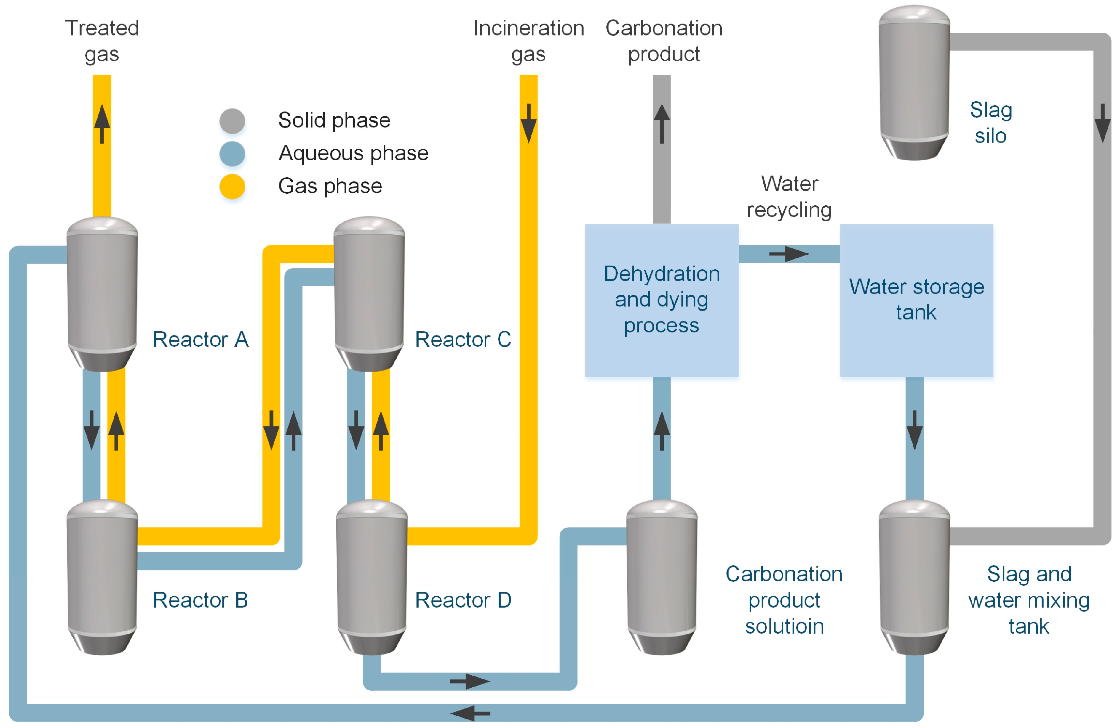
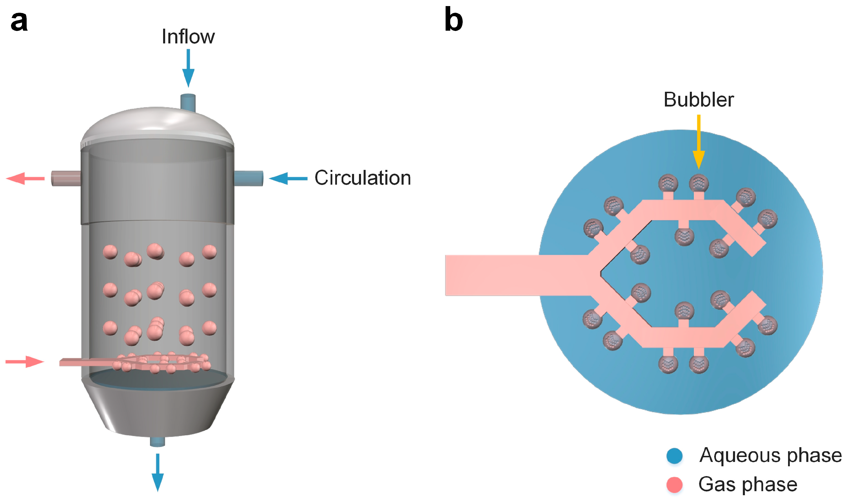
2. Process and Operation for Mineral Carbonation Plant

The mineral carbonation plant operated in this study is located at the Seongam Incinerator in Ulsan Metropolitan City, Republic of Korea. In 2021, Ulsan Metropolitan City had an area of 1062.3 km2 and a population of 1,138,419, and was designated as a CO2 Resource Special Regulatory Free Zone on 13 November 2020 [26]. Ulsan Metropolitan City, with many large-scale industrial complexes, GHG target management companies, and businesses subject to the GHG emissions trading scheme, has made excellent efforts to achieve carbon neutrality [26]. A schematic diagram of the mineral carbonation plant process operated in this study is shown in Figure 1. The plant with a CO2 capture capacity of 5 tons/day has four reactors. As illustrated, Reactors A and B, and Reactors C and D are arranged vertically, and the slag mixture flows from Reactor A to Reactor D, and the exhaust gas from the incinerator flows from Reactor D to Reactor A. CO2 measurements of the inflow and outflow gases were performed at the front end of Reactor D and the rear end of Reactor A. In our study, the pH values were measured at all four reactors, and the reaction was terminated from the reactor close to the gas inlet point. The mixture can be transferred to the carbonation product solution tank only via Reactor D. We designed the vertical arrangement to operate the plant without separate power using the gravity energy from the movement of the slag mixture from Reactor A to Reactor B and Reactor C to Reactor D. The operation of the mineral carbonation plant is initiated by mixing steel slag and tap water in a slag and water mixing tank. In this study, steel slag with a size of ~300 mesh is applied. The reactors are first filled with the mixture, then the exhaust gas from the incinerator is introduced into the reactors. The reaction can be stopped by adjusting the pH to 6. It is noted that Tu et al. reported that the initial pH of the slurry showed a sharp decrease from 11 to 8.5 and stabilization at ~6.5 in the aqueous carbonation of steel slag [27,28] because carbonate ions dominate at a pH > 10.3 and bicarbonate ions dominate at a pH < 8.4 [27]. Equation (1) can represent its mechanisms [29]. Therefore, if carbonate ions are more abundant than bicarbonate ions, H+ also becomes more abundant. An increase in H+ leads to a decreased pH, increased dissolution of Ca2+, and accelerated mineral carbonation [29,30]. However, below the pH value of 6, CO2 becomes more dominant than bicarbonate ions and exists in dissolved form, resulting in a decrease in the formation of CaCO3 [31]. Equations (2)–(4) show mineral carbonation [29,32].
C O 2 a q + H 2 O H 2 C O 3 H C O 3 + H + C O 3 2 + 2 H +
C a O H 2 a q C a 2 + + 2 O H
C a 2 + + H C O 3 C a C O 3 + H +
C a 2 + + C O 3 2 C a C O 3
Gu et al. used an aqueous solution of Ca(OH)2 at 25 °C and 30 mM to determine the ratio of calcium to pH [33]. They reported that below pH = 12.6, Ca2+ dominated Ca(OH)2 in proportion and that pH~12, Ca(OH)2 was fully converted to Ca2+ [33]. They also observed decreased CaCO3 and increased Ca2+ at pH < 6 [33]. Accordingly, it was determined to terminate the reaction of mineral carbonation at pH ≥ 6 [34,35].
Figure 2 is a schematic diagram of the reactor of the mineral carbonation plant operated in this study. The reactor’s capacity is 10 m3, and the gas phase is introduced from the bottom and discharged from the top. To improve the efficiency of the carbonation reaction, the gas phase is introduced into the liquid phase through bubblers, and 18 bubblers are attached to each reactor. The steel slag mixture is introduced from the top and discharged from the bottom, and the mixture is circulated to increase the stirring efficiency. Table 1 shows the characteristics of the gas entering the reactor of the mineral carbonation plant. During the operation, the average flow rate and temperature of the reactor gas entering were about 1550 Nm3/hr and 90 ℃, respectively, and the average concentration of CO2 in the inflow gas and the inflow rate were 10% and 300 kg/h, respectively. In addition, to evaluate the CO2 removal efficiency for the inflow gas, the CO2 sequestration efficiency and rate were calculated using the flow rate and CO2 concentration of the outflow gas. The CO2 sequestration efficiency and rate can be calculated using Equations (5) and (6).
C O 2   s e q u e s t r a t i o n   e f f i c i e n c y   ( % ) = 1 B ( 100 B ) A ( 100 A ) × 100
C O 2   s e q u e s t r a t i o n   r a t e   ( k g / h r ) = { C × A 100 × 44.01 22.4 } { D × B 100 × 44.01 22.4 }
  • A = CO2 concentration in inflow gas (%);
  • B = CO2 concentration in outflow gas (%);
  • C = Inflow gas rate (Nm3/hr);
  • D = Outflow gas rate (Nm3/hr).
where A and B are the CO2 concentrations entering Reactor D and leaving Reactor A, respectively, and Reactors C and D are the gas flow rates entering Reactor D and leaving Reactor A, respectively. In addition, 44.01 and 22.4 are 44.01 kg/kmole-CO2 and 22.4 m3/kmole-CO2, respectively. In this study, it is noted that we also investigated the feasibility of fully recycling water.

3. Materials and Methods

To characterize the steel slag and mineral carbonation products, particle size analysis (PSA), specific gravity, Brunauer–Emmet–Teller (BET), X-ray fluorescence analysis (XRF), loss on drying (LOD), loss on ignition (LOI), free CaO, and thermogravimetric analysis (TGA) were performed. Two and nineteen samples of the steel slag and mineral carbonation products, respectively, were used to obtain reliable results. PSA and specific gravity were conducted to determine the changes in particle size and specific gravity due to the carbonation reaction of the steel slag. The measurement ranges of the particle size analyzer (LA-960, HORIBA, Irvine, CA, USA) was 0.01~5000 μm, the light source was a 650 nm laser diode with ~5.0 mW, and the detectors were silicon photodiodes. The specific gravity was measured using a specific gravity bottle. BET was used to measure the specific surface area to check the change of pores due to the carbonation reaction of the steel slag. The specific surface area meter (QUADRASORB evo, Anton Paar, Graz, Austria) used nitrogen as the analysis gas, and the bath temperature was 77.3 K. An XRF was performed to determine the elements of the steel slag and mineral carbonation products. A wavelength dispersive XRF spectrometer (S8 TIGER, BRUKER, Billerica, MA, USA) equipped with a rhodium (Rh) tube with a 75-μm Be window was used. LOD and LOI were conducted for the proximate analysis of the steel slag and mineral carbonation products according to the process of the mineral carbonation plant, and the LOD was measured via the weight change after 5 h at 105 °C and the LOI after 2 h at 1000 °C. Free CaO was tested to evaluate the stability of the mineral carbonation products from the carbonation reactions for use as construction materials. The analysis of free CaO was determined by titration with a hydrochloric acid solution. TGA was performed using a thermogravimetric analyzer (TGA 5500, TA Instruments, New Castle, DE, USA), and the content of CaCO3 and CaO as CaCO3 was estimated using the thermal decomposition amount of 500–800 °C under nitrogen conditions up to 900 °C at a heating rate of 20 °C/min. The content of CaO as CaCO3 was calculated using Equation (7).
C a O   a s   C a C O 3   ( % ) = ( L o s s   o f   m a s s   f o r   500 800   ° C ( % ) / 44.01 ) × 56.08
where 44.01 and 56.08 are 44.01 kg/kmol-CO2 and 56.08 kg/kmol-CaO, respectively. We also estimated the conversion of CaO from the total CaO result of XRF, and the equation is shown in Equation (8).
C o n v e r s i o n   r a t e   ( % ) = [ { ( A B ) ( C D ) } / ( A B ) ] × 100
  • A = Total CaO in steel slag (%);
  • B = CaO as CaCO3 in steel slag (%);
  • C = Total CaO in mineral carbonation products (%);
  • D = CaO as CaCO3 in mineral carbonation products (%);
  • A–B = Residue CaO in steel slag (%);
  • C–D = Residue CaO in mineral carbonation products (%).
where A and B are the total CaO and CaO as CaCO3 in the steel slag, respectively, and C and D are the total CaO and CaO as CaCO3 in the mineral carbonation products, respectively. It is noted that this formula does not account for CaSO4 [36,37,38]. Since the exhaust gases applied for CO2 mineralization were obtained from the end of the telemonitoring system of the incinerator stack, we assumed that the effect of SOx would be much less than that of CO2.

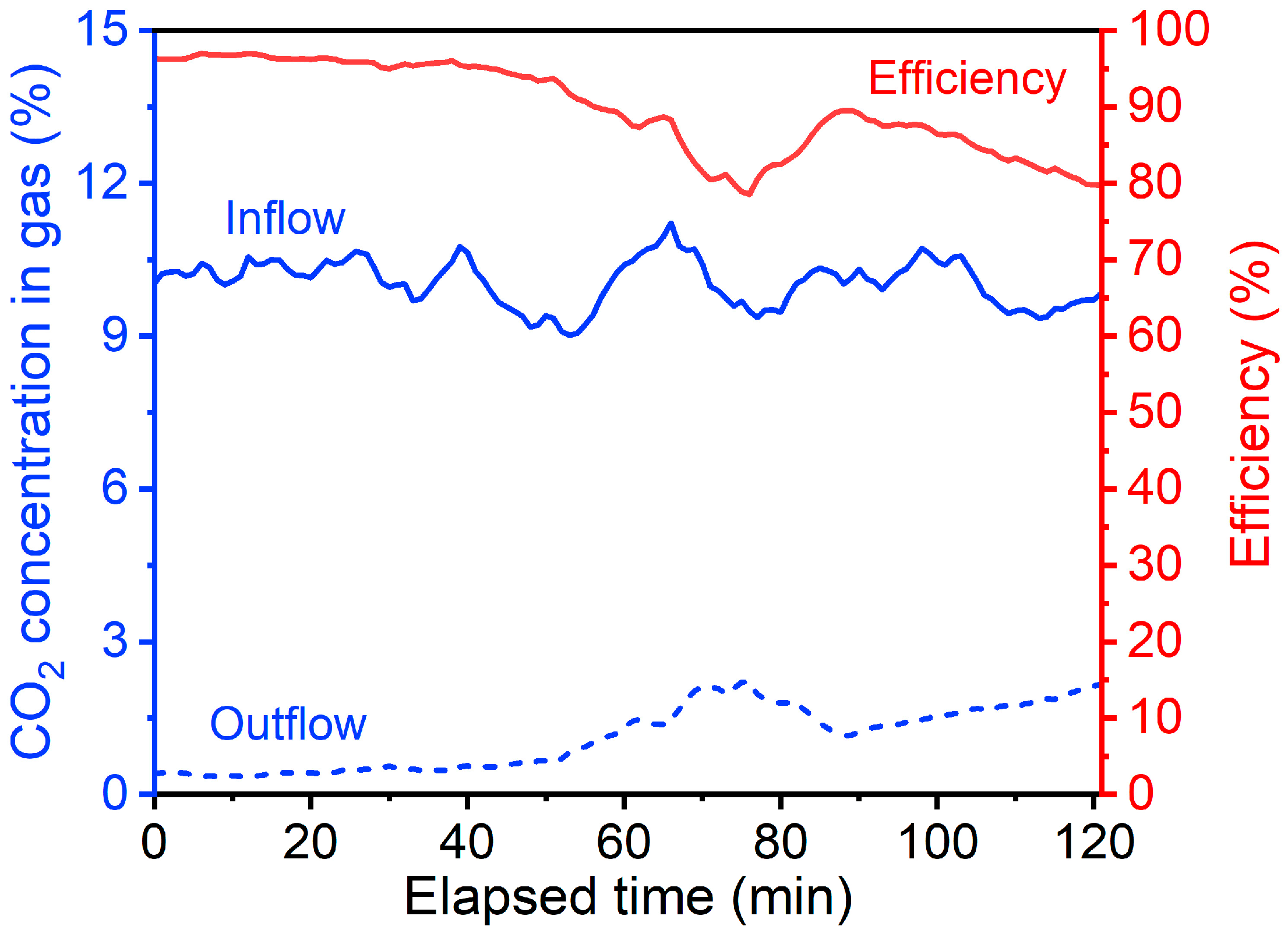
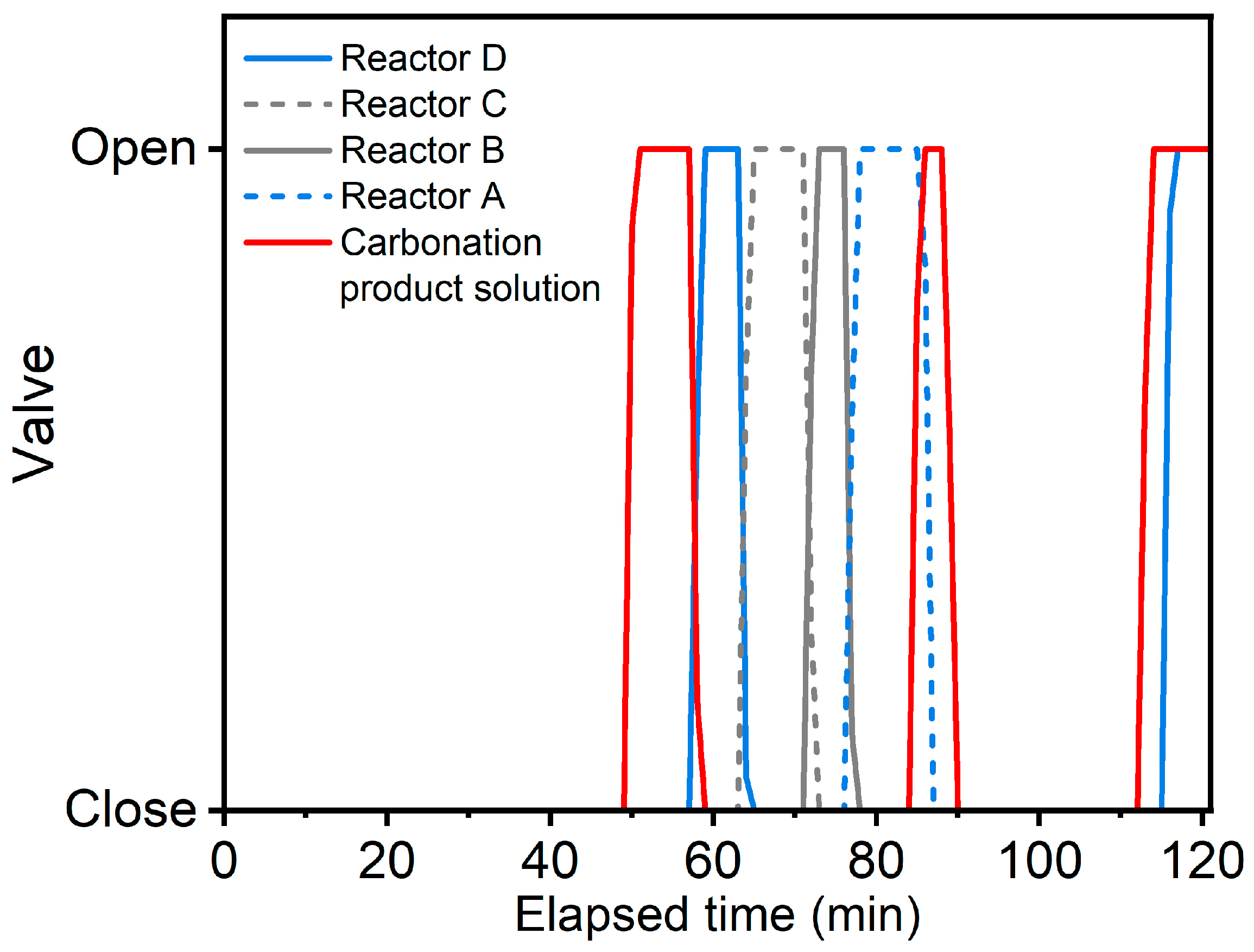
4. Results and Discussion

The CO2 concentration variation and CO2 sequestration efficiency of the inflow and outflow gases over time are summarized in Figure 3. As the mineral carbonation reaction occurred rapidly after interacting with the reactant gases, we collected the data after a 5 min stabilization time after the gas injection. The average concentration of CO2 in the inflow and outflow gases during the reaction time was 10.0% and 1.1%, respectively, and the average CO2 sequestration efficiency was 89.7%. Figure 4 shows the opening of the valve as a function of time, indicating the mixture’s movement. Therefore, the mixture was transferred from Reactor D to the carbonation product solution tank at 50 min from the start of the reaction, and the mixture was sequentially transferred to Reactor D from 58 min to 77 min. This showed that, from the initial reaction to the transfer from Reactor D to the carbonation product solution tank, the CO2 sequestration efficiency was 95.8% in State 1 (reaction time 0–50 min) when four reactors were filled with the mixture, and 84.7% in State 2 (reaction time 58–77 min) when three reactors were filled with the mixture during the reaction. After 77 min, the unreacted mixture was transferred to Reactor A, and the mixture was transferred from Reactor D to the carbonation product solution tank. As a result, the CO2 sequestration efficiency was 85.8% in State 3 (reaction time 77–113 min), with one reactor filled with the unreacted mixture and two reactors filled with the reacting mixture. Therefore, the CO2 sequestration efficiency reached the highest in State 1, followed by States 3 and 2. Although the average value of CO2 sequestration efficiency was not significantly different between State 2 and State 3, the time for CO2 sequestration efficiency to drop to about 80% was about twice as long in State 3 as in State 2.
Table 2 shows the CO2 sequestration efficiency, rate, and capacity at different Sates. The gas rate and CO2 concentration in gas affect the CO2 sequestration rate, as shown in Equation (6). The CO2 sequestration rate in State 1 was the lowest, while the CO2 sequestration capacity was the largest. Therefore, although there was no significant difference in CO2 sequestration efficiency between State 2 and State 3, the CO2 sequestration capacity and gram of CO2 per kg of steel slag in State 2 became double that of State 3 in comparison. Additionally, it was found that State 3 exhibited higher grams of CO2 per kg of steel slag than State 1, even if the unreacted mixture was in one reactor. We found that the more reactors that were filled with mixtures, the less the gas flow rate was loaded, consequently leading to less active contact with the reactants.
Table 3 shows the PSA, specific gravity, and BET of the steel slag and mineral carbonation products. The PSA analysis of the steel slag and mineral carbonation products confirmed that the median decreased from 31.7 μm to 15.6 μm and the mean increased slightly from 54.5 μm to 58.9 μm. Ho et al. conducted wet direct carbonation experiments using the dephosphorization slag. They reported that as the carbonation reaction time increased, the CaCO3 particles became smaller via the collision of the initially large particles and the larger solidity ratio [39]. Therefore, it can be concluded that large CaCO3 particles were initially formed via calcium ions from the steel slag, followed by collision processes as the reaction progressed, leading to smaller median particle sizes. However, we also observed that the mean particle size was increased, assuming that it may result from non-colliding CaCO3 particles. In addition, the specific gravity of the mineral carbonation products decreased by about 0.2 compared to the steel slag due to the formation of calcium carbonate, which has a smaller specific gravity than steel slag. The decrease in specific gravity resulted in an increase in BET from 11.9 m2/g to 44.7 m2/g. This means the mineral carbonation products have more pores than the steel slag. Chen et al. [20] characterized the carbonation of basic oxygen furnace slag and found that the density of carbonated basic oxygen furnace slag decreased from 3.13 g/cm3 to 2.66 g/cm3, and the Blaine Fineness increased from 672 m2/kg to 1020 m2/kg, showing a similar trend to this study [40]. Figure 5 shows the characterization results for the XRF, LOD, and LOI of steel slag and mineral carbonation. The CaO content of steel slag was 44.6%, while that of the mineral carbonation products was 31%. It is considered that the LOD of the steel slag increased due to the wet carbonation reaction, and the LOI increased due to the formation of calcium carbonate. The formation of calcium carbonate can be confirmed via free CaO and TGA [20,40], and the free CaO and TGA results are shown in Table 4. The free CaO in the steel slag was reduced from 7.8% to 0.3% via the carbonation reaction, and the weight loss of TGA from 500 to 800 °C increased from 5.3% to 21.6%. These results are consistent with the study by Chen et al. [40]. It was reported that basic oxygen furnace slag with a content of 1.02% free CaO was not found after carbonation, and the TGA analysis showed that the DTG peak of calcium hydroxide (441 °C) disappeared and the DTG peak of calcium carbonate (775 °C) intensified with carbonation [40]. Therefore, it is anticipated that most of the free CaO and calcium hydroxide contained in the steel slag can be removed through the carbonation reaction. In addition, the conversion rate of CaO is >90%, according to XRF and TGA analyses. Wang reported that free CaO is the main cause of the volume expansion of steel slag; the reason for this is that when free CaO reacts with water to produce calcium hydroxide, the volume increases by about 90% [41]. Accordingly, we assumed that the mineral carbonation products are more stable than steel slag as a construction material and are effective at sequestering CO2 by forming chemically stable calcium carbonate [42]. Therefore, when there is great concern about the concentration of CO2 in the atmosphere, utilizing mineral carbonation products as a construction material can bring great environmental benefits in terms of recycling steel slag and the sequestration of greenhouse gases [43].

5. Conclusions

This study assessed the amount of CO2 captured and the sequestration efficiency of the carbonation plant to capture CO2 in the emissions of a municipal waste incinerator. In addition, the characteristics of the mineral carbonation products were identified to suggest ways to utilize the products. In this study, the CO2 sequestration efficiency reached 95.8% in State 1 (reaction time: 0–50 min) when four reactors were filled with the mixture, while it became 84.7% in State 2 (reaction time: 58–77 min) by filling three reactors with the mixture during the reaction. After 77 min, the unreacted mixture was transferred to Reactor A, and then, the mixture was transferred from Reactor D to the carbonation product solution tank. This resulted in a CO2 sequestration efficiency of 85.8% in State 3 (reaction time: 77–113 min), with one reactor filled with the unreacted mixture and two reactors filled with the reacted mixture. We observed that the CO2 sequestration rate in State 1 was the lowest, while its CO2 sequestration capacity was the largest as the gas rate and CO2 concentration in gas affect the CO2 sequestration rate. Therefore, we found that State 3, with fewer filled reactors, received less load on the gas flow rate, leading to more active contact between the gas reactant liquid. Then, consequently, the CO2 sequestration rate and the carbon sequestration in grams of CO2 per kg of steel slag were higher. We observed a conversion rate of CaO of >90%. Our plant-wide experimental findings suggested mineral carbonation products are more stable than steel slag as a construction material and are effective in sequestering CO2 by forming chemically stable CaCO3. Therefore, when there is great concern about the concentration of CO2 in the atmosphere, utilizing mineral carbonation products as a construction material can bring significant environmental benefits in terms of recycling steel slag and the sequestration of greenhouse gases [44]. It is proposed that environmental exposures, such as the long-term heavy metal leaching from construction materials utilizing mineral carbonation products, should be evaluated, and more economic studies should be conducted based on this study [45]. Furthermore, studies on the effect of carbonation on heavy metal leaching from steel slags are also highly recommended [46]. For the proper utilization of mineral carbonation products, it is also desirable to accurately characterize all of the minerals of reactants and products under different operating conditions using X-ray diffraction (XRD) analysis [46], verifying the mineralogical reactions in detail. The outcomes can be applied to rationally designing futuristic experimental systems.

Author Contributions

Conceptualization, H.L.; methodology, H.L.; software, H.L.; validation, S.H.K. and C.C.; investigation, T.W.K.; writing—original draft preparation, H.L.; writing—review and editing, Y.-W.L., C.-T.L., Y.C. and C.C.; supervision, C.C.; project administration, C.C.; funding acquisition, C.C. All authors have read and agreed to the published version of the manuscript.

Funding

This research was funded by the Ministry of SMEs and Startups of Korea (Project No. P0016558). Y.C. acknowledges the National Science and Technology Council of Taiwan (NSTC Grant No. 111-2221-E-A49-003-MY3).

Data Availability Statement

Not applicable.

Conflicts of Interest

The authors declare no conflict of interest.

References

  1. Lindsey, R. Climate Change: Atmospheric Carbon Dioxide. Available online: https://www.climate.gov/news-features/understanding-climate/climate-change-atmospheric-carbon-dioxide (accessed on 16 April 2023).
  2. IEA. Global Energy Review: CO2 Emissions in 2021—Global Emissions Rebound Sharply to Highest Ever Level; IEA: Paris, France, 2022. [Google Scholar]
  3. Jones, M.W.; Peters, G.P.; Gasser, T.; Andrew, R.M.; Schwingshackl, C.; Gütschow, J.; Houghton, R.A.; Friedlingstein, P.; Pongratz, J.; Le Quéré, C. National contributions to climate change due to historical emissions of carbon dioxide, methane, and nitrous oxide since 1850. Sci. Data 2023, 10, 155. [Google Scholar] [CrossRef] [PubMed]
  4. Riahi, K.; Schaeffer, R.; Arango, J.; Calvin, K.; Guivarch, C.; Hasegawa, T.; Jiang, K.; Kriegler, E.; Matthews, R.; Peters, G.P. Mitigation pathways compatible with long-term goals. In Sixth Assessment Report of the Intergovernmental Panel on Climate Change; Cambridge University Press: Cambridge, UK, 2022; pp. 295–408. [Google Scholar]
  5. Watari, T.; Cao, Z.; Hata, S.; Nansai, K. Efficient use of cement and concrete to reduce reliance on supply-side technologies for net-zero emissions. Nat. Commun. 2022, 13, 4158. [Google Scholar] [CrossRef]
  6. Leung, D.Y.C.; Caramanna, G.; Maroto-Valer, M.M. An overview of current status of carbon dioxide capture and storage technologies. Renew. Sustain. Energy Rev. 2014, 39, 426–443. [Google Scholar]
  7. Eldardiry, H.; Habib, E. Carbon capture and sequestration in power generation: Review of impacts and opportunities for water sustainability. Energy Sustain. Soc. 2018, 8, 6. [Google Scholar]
  8. Pisciotta, M.; Pilorgé, H.; Feldmann, J.; Jacobson, R.; Davids, J.; Swett, S.; Sasso, Z.; Wilcox, J. Current state of industrial heating and opportunities for decarbonization. Prog. Energy Combust. Sci. 2022, 91, 100982. [Google Scholar] [CrossRef]
  9. Kuwahara, Y.; Hanaki, A.; Yamashita, H. Direct Synthesis of a Regenerative CaO–Fe3O4–SiO2 Composite Adsorbent from Converter Slag for CO2 Capture Applications. ACS Sustain. Chem. Eng. 2022, 10, 372–381. [Google Scholar] [CrossRef]
  10. Wang, J.-W.; Kang, J.-N.; Liu, L.-C.; Nistor, I.; Wei, Y.-M. Research trends in carbon capture and storage: A comparison of China with Canada. Int. J. Greenh. Gas Control. 2020, 97, 103018. [Google Scholar]
  11. Zhao, Q.; Chu, X.; Mei, X.; Meng, Q.; Li, J.; Liu, C.; Saxén, H.; Zevenhoven, R. Co-treatment of Waste From Steelmaking Processes: Steel Slag-Based Carbon Capture and Storage by Mineralization. Front. Chem. 2020, 8, 571504. [Google Scholar] [CrossRef]
  12. Zhao, Q.; Liu, K.; Sun, L.; Liu, C.; Jiang, M.; Saxén, H.; Zevenhoven, R. Towards carbon sequestration using stainless steel slag via phase modification and co-extraction of calcium and magnesium. Process Saf. Environ. Prot. 2020, 133, 73–81. [Google Scholar] [CrossRef]
  13. Sun, Y.; Tian, S.; Ciais, P.; Zeng, Z.; Meng, J.; Zhang, Z. Decarbonising the iron and steel sector for a 2  °C target using inherent waste streams. Nat. Commun. 2022, 13, 297. [Google Scholar] [CrossRef]
  14. Liu, J.; Yu, B.; Wang, Q. Application of steel slag in cement treated aggregate base course. J. Clean. Prod. 2020, 269, 121733. [Google Scholar] [CrossRef]
  15. Menad, N.-E.; Kana, N.; Seron, A.; Kanari, N. New EAF Slag Characterization Methodology for Strategic Metal Recovery. Materials 2021, 14, 1513. [Google Scholar] [CrossRef]
  16. Ho, H.-J.; Iizuka, A. Mineral carbonation using seawater for CO2 sequestration and utilization: A review. Sep. Purif. Technol. 2023, 307, 122855. [Google Scholar] [CrossRef]
  17. Vassilev, S.V.; Vassileva, C.G.; Petrova, N.L. Mineral Carbonation of Biomass Ashes in Relation to Their CO2 Capture and Storage Potential. ACS Omega 2021, 6, 14598–14611. [Google Scholar] [CrossRef]
  18. Vinoba, M.; Bhagiyalakshmi, M.; Choi, S.Y.; Park, K.T.; Kim, H.J.; Jeong, S.K. Harvesting CaCO3 Polymorphs from In Situ CO2 Capture Process. J. Phys. Chem. C 2014, 118, 17556–17566. [Google Scholar] [CrossRef]
  19. Vassilev, S.V.; Vassileva, C.G. Extra CO2 capture and storage by carbonation of biomass ashes. Energy Convers. Manag. 2020, 204, 112331. [Google Scholar] [CrossRef]
  20. Coppola, A.; Scala, F.; Azadi, M. Direct Dry Carbonation of Mining and Industrial Wastes in a Fluidized Bed for Offsetting Carbon Emissions. Processes 2022, 10, 582. [Google Scholar] [CrossRef]
  21. Mazzotti, M.; Abanades, J.C.; Allam, R.; Lackner, K.S.; Meunier, F.; Rubin, E.; Sanchez, J.C.; Yogo, K.; Zevenhoven, R. 7-Mineral carbonation and industrial uses of carbon dioxide. In IPCC Special Report on Carbon Dioxide Capture and Storage; Cambridge University Press: Cambridge, UK, 2005. [Google Scholar]
  22. Ji, L.; Yu, H. 2-Carbon dioxide sequestration by direct mineralization of fly ash. In Carbon Dioxide Sequestration in Cementitious Construction Materials; Pacheco-Torgal, F., Shi, C., Sanchez, A.P., Eds.; Woodhead Publishing: Sawston, UK, 2018; pp. 13–37. [Google Scholar]
  23. Rushendra Revathy, T.D.; Palanivelu, K.; Ramachandran, A. Direct mineral carbonation of steelmaking slag for CO2 sequestration at room temperature. Environ. Sci. Pollut. Res. 2016, 23, 7349–7359. [Google Scholar] [CrossRef]
  24. Baciocchi, R.; Costa, G.; Di Gianfilippo, M.; Polettini, A.; Pomi, R.; Stramazzo, A. Thin-film versus slurry-phase carbonation of steel slag: CO2 uptake and effects on mineralogy. J. Hazard. Mater. 2015, 283, 302–313. [Google Scholar] [CrossRef]
  25. Sanna, A.; Uibu, M.; Caramanna, G.; Kuusik, R.; Maroto-Valer, M.M. A review of mineral carbonation technologies to sequester CO2. Chem. Soc. Rev. 2014, 43, 8049–8080. [Google Scholar] [CrossRef]
  26. Tu, M.; Zhao, H.; Lei, Z. The Ulsan Metropolitan City, 2022 Municipal White Paper. July 2022. Available online: https://www.ulsan.go.kr/u/rep/contents.ulsan?mId=001003004001000000 (accessed on 16 April 2023).
  27. Wang, L.; Chen, D.; Yu, H.; Qi, T. Aqueous Carbonation of Steel Slag: A Kinetics Study. ISIJ Int. 2015, 55, 2509–2514. [Google Scholar]
  28. Ragipani, R.; Sreenivasan, K.; Anex, R.P.; Zhai, H.; Wang, B. Direct Air Capture and Sequestration of CO2 by Accelerated Indirect Aqueous Mineral Carbonation under Ambient Conditions. ACS Sustainable Chem. Eng. 2022, 10, 7852–7861. [Google Scholar] [CrossRef]
  29. Matter, J.M.; Kelemen, P.B. Permanent storage of carbon dioxide in geological reservoirs by mineral carbonation. Nat. Geosci. 2009, 2, 837–841. [Google Scholar] [CrossRef]
  30. Wang, D.; Xiong, C.; Li, W.; Chang, J. Growth of Calcium Carbonate Induced by Accelerated Carbonation of Tricalcium Silicate. ACS Sustain. Chem. Eng. 2020, 8, 14718–14731. [Google Scholar] [CrossRef]
  31. Pedersen, O.; Colmer, T.; Sand-Jensen, K. Underwater Photosynthesis of Submerged Plants—Recent Advances and Methods. Front. Recent Dev. Plant Sci. 2013, 4, 140. [Google Scholar] [CrossRef]
  32. Mathur, V.K. High Speed Manufacturing Process for Precipitated Calcium Carbonate Employing Sequential Perssure Carbonation. U.S. Patent 6,251,356, 26 June 2001. [Google Scholar]
  33. Gu, S.; Fu, B.; Fujita, T.; Ahn, J.W. Thermodynamic Simulations for Determining the Recycling Path of a Spent Lead-Acid Battery Electrolyte Sample with Ca(OH)2. Appl. Sci. 2019, 9, 2262. [Google Scholar] [CrossRef]
  34. Yuan, Q.; Zhang, Y.; Wang, T.; Wang, J.; Romero, C.E. Mineralization characteristics of coal fly ash in the transition from non-supercritical CO2 to supercritical CO2. Fuel 2022, 318, 123636. [Google Scholar] [CrossRef]
  35. Li, Y.; Duan, X.; Song, W.; Ma, L.; Jow, J. Reaction mechanisms of carbon dioxide capture by amino acid salt and desorption by heat or mineralization. Chem. Eng. J. 2021, 405, 126938. [Google Scholar] [CrossRef]
  36. Lu, H.; Smirniotis, P.G. Calcium Oxide Doped Sorbents for CO2 Uptake in the Presence of SO2 at High Temperatures. Ind. Eng. Chem. Res. 2009, 48, 5454–5459. [Google Scholar] [CrossRef]
  37. Marques, L.M.; Mota, S.M.; Teixeira, P.; Pinheiro, C.I.C.; Matos, H.A. Ca-looping process using wastes of marble powders and limestones for CO2 capture from real flue gas in the cement industry. J. CO2 Util. 2023, 71, 102450. [Google Scholar] [CrossRef]
  38. Liu, X.; Zou, Y.; Geng, R.; Zhu, T.; Li, B. Simultaneous Removal of SO2 and NOx Using Steel Slag Slurry Combined with Ozone Oxidation. ACS Omega 2021, 6, 28804–28812. [Google Scholar] [CrossRef] [PubMed]
  39. Ho, H.-J.; Iizuka, A.; Kubo, H. Direct aqueous carbonation of dephosphorization slag under mild conditions for CO2 sequestration and utilization: Exploration of new dephosphorization slag utilization. Environ. Technol. Innov. 2022, 28, 102905. [Google Scholar] [CrossRef]
  40. Chen, K.-W.; Pan, S.-Y.; Chen, C.-T.; Chen, Y.-H.; Chiang, P.-C. High-gravity carbonation of basic oxygen furnace slag for CO2 fixation and utilization in blended cement. J. Clean. Prod. 2016, 124, 350–360. [Google Scholar] [CrossRef]
  41. Wang, G.C. The Utilization of Slag in Civil Infrastructure Construction; Woodhead Publishing: Sawston, UK, 2016. [Google Scholar]
  42. Krödel, M.; Landuyt, A.; Abdala, P.M.; Müller, C.R. Mechanistic Understanding of CaO-Based Sorbents for High-Temperature CO2 Capture: Advanced Characterization and Prospects. ChemSusChem 2020, 13, 6259–6272. [Google Scholar] [PubMed]
  43. O’Connor, J.; Nguyen, T.B.T.; Honeyands, T.; Monaghan, B.; O’Dea, D.; Rinklebe, J.; Vinu, A.; Hoang, S.A.; Singh, G.; Kirkham, M.B.; et al. Production, characterisation, utilisation, and beneficial soil application of steel slag: A review. J. Hazard. Mater. 2021, 419, 126478. [Google Scholar] [CrossRef]
  44. Lee, J.; Ryu, K.H.; Ha, H.Y.; Jung, K.-D.; Lee, J.H. Techno-economic and environmental evaluation of nano calcium carbonate production utilizing the steel slag. J. CO2 Util. 2020, 37, 113–121. [Google Scholar] [CrossRef]
  45. Subraveti, S.G.; Rodríguez Angel, E.; Ramírez, A.; Roussanaly, S. Is Carbon Capture and Storage (CCS) Really So Expensive? An Analysis of Cascading Costs and CO2 Emissions Reduction of Industrial CCS Implementation on the Construction of a Bridge. Environ. Sci. Technol. 2023, 57, 2595–2601. [Google Scholar] [CrossRef]
  46. Vollprecht, D.; Wohlmuth, D. Mineral Carbonation of Basic Oxygen Furnace Slags. Recycling 2022, 7, 84. [Google Scholar] [CrossRef]
Figure 1. A schematic illustration of the process for the mineral carbonation plant.
Processes 11 01676 g001
Figure 2. (a) Side view and (b) top view of the reactor used in this study.
Processes 11 01676 g002
Figure 3. Variation of CO2 concentration and CO2 sequestration efficiency of the inflow and outflow gases as a function of time.
Processes 11 01676 g003
Figure 4. Valve positions for reactors as a function of time.
Processes 11 01676 g004
Figure 5. XRF, LOD, and LOI analyses for (a) steel slag and (b) mineral carbonation products.
Processes 11 01676 g005
Table 1. Parameters for the inflow gas to the reactors in the mineral carbonation plant.
Inflow Gas Rate
(Nm3/hr)
Temperature of
Inflow Gas (°C)
CO2 Concentration in Inflow Gas (%)Inflow CO2 Rate
(kg/hr)
155588.410.0305
Table 2. The CO2 sequestration efficiency, rate, and capacity at different States.
StateReaction Time
(min)
CO2 Sequestration
Efficiency (%)Rate (kg/h)Capacity (kg)g-CO2/kg-Steel Slag
10–5095.8246.4205.379.9
258–7784.7271.686.044.6
377–11385.8308.6185.297.7
Table 3. Characterization results using PSA, specific gravity, and BET for steel slag and mineral carbonation products.
CategorySteel SlagMineral Carbonation Products
PSA (μm)Median31.715.6
Mean54.458.9
Specific gravity2.22.0
BET (m2/g)11.944.7
Table 4. Mass loss of TGA (500–800 °C), the content of free CaO, CaCO3, CaO as CaCO3, and residue CaO, and the conversion of CaO for steel slag and mineral carbonation products.
CategorySteel SlagMineral Carbonation Products
Mass loss of TGA (%)5.321.6
Free CaO (%)7.80.3
CaCO3 (%)12.149.2
CaO as CaCO3 (%)6.827.6
Residue CaO (%)37.83.4
Conversion CaO (%)-90.9
Disclaimer/Publisher’s Note: The statements, opinions and data contained in all publications are solely those of the individual author(s) and contributor(s) and not of MDPI and/or the editor(s). MDPI and/or the editor(s) disclaim responsibility for any injury to people or property resulting from any ideas, methods, instructions or products referred to in the content.

