Article

Study on Adaptive Parameter Internal Mode Control Method for Argon–Oxygen Refining Ferrochrome Alloy

1
School of Medical Information, Changchun University of Chinese Medicine, Changchun 130117, China
2
School of Mechanical and Electrical Engineering, Changchun University of Technology, Changchun 130012, China
3
School of Electrical and Electronic Engineering, Changchun University of Technology, Changchun 130012, China
4
School of Energy and Environmental Engineering, Jilin Institute of Architecture and Technology, Changchun 130114, China
*
Author to whom correspondence should be addressed.
Processes 2023, 11(5), 1461; https://doi.org/10.3390/pr11051461
Submission received: 11 April 2023 / Revised: 4 May 2023 / Accepted: 9 May 2023 / Published: 11 May 2023
(This article belongs to the Special Issue Modeling, Simulation, Control, and Optimization of Processes)

Abstract

:
In order to determine a way to be able to shorten the smelting time of low-carbon ferrochrome alloys and to strengthen the temperature control capability of the AOD converter during the smelting process, this article establishes a mechanism model of the rate of oxygen supply and carbon content change in the smelting process as well as the temperature of the reaction fluid in the converter. The physical and chemical reactions of the smelting process and the actual smelting data are used as the basis. The temperature and carbon content in the smelting converter are considered as the output quantity and the rate of oxygen supply is considered as the input quantity. An expert internal model control framework is built. In addition, an adaptive parameter adjustment mechanism is added to the control framework, taking into account data such as the maximum gas supply rate and the maximum limiting temperature of the actual production process. This method improves the smelting speed and smelting accuracy compared to the general internal mode control method. Finally, according to this method, with the use of the built low-carbon ferrochrome alloy centralized control system for smelting, the system shortens the smelting time by 12.79% compared with the general method and controls the converter temperature below 1950 K, which achieves the expected goal according to the simulation and actual smelting results.

1. Introduction

Ferrochrome is an iron alloy consisting of chromium and iron. It is an important raw material for the refining of stainless steel [1]. Ferrochrome alloys can be divided into high-carbon ferrochrome, low-carbon ferrochrome and low-carbon ferrochrome according to their different carbon contents [2]. The chromium content of the three products is basically the same. Due to the smelting process, high-carbon ferrochrome has a higher impurity content. High-carbon ferrochrome is mainly used for the production of high-speed steel alloys with high carbon content [3]. It is also the main raw material for the production of low- and medium-carbon ferrochrome and for the production of chromium metal using the electrolytic process. Medium-carbon ferrochrome is produced by decarburizing high-carbon ferrochrome and is mainly used in the production of low and medium carbon structural steels [4]. There are also some applications in the production of chromium–manganese silicon steel, which is the main raw material for the manufacture of high-pressure valves. Low-carbon ferrochrome is also produced by decarburizing high-carbon ferrochrome. It is the main raw material for the production of stainless steels, nuclear steels, highly corrosion-resistant steels and those highly resistant to strong acids. Low-carbon ferrochrome is used as a heating agent as it generates a large amount of heat when enflamed at high temperatures.
The AOD process is short for Argon Oxygen Refining Decarburization method [5]. It is one of the most important means of producing low-carbon ferrochrome. The equipment used is given the name AOD converter because of the process. The structure of the AOD converter is similar to that of a regular converter and its main structure is shown in Figure 1. The AOD converter contains three oxygen lances, including a top lance and two bottom lances. The AOD converter body is charged and discharged at the converter mouth. The converter body is therefore fixed in a tiltable support ring, a construction which allows the converter body to be rotated 180° both before and after [6]. During smelting, the liquid ferrochrome alloy, which has been roughly refined in the electric converter, is poured into the AOD converter. The AOD converter is held in a vertical position. The top lance is then lowered and oxygen is blown in for the decarburization process, as shown in Figure 1. The smelting process can be carried out in stages according to the actual control method. However, the decarburization process is generally carried out at 8% to 1% of the carbon content of the raw material, and the maximum gas supply can be used continuously [7,8]. In the later stages of the smelting process, when the carbon content is roughly 1%, in order to avoid wasting oxygen and argon, only the bottom lance is used for the gas supply. The argon gas blown in at this point also acts as an agitator [9].
The production process of low-carbon ferrochrome products using an AOD converter is complex. The process uses high-carbon ferrochrome as the raw material for decarburization by blowing in oxygen. Argon gas acts as a pressure divider. The amount of oxygen and argon to be blown in needs to be judged according to the different smelting conditions [10]. A low-carbon ferrochrome is obtained with a carbon content that meets the conditions. The most important parameters of the process include the carbon content at the end of smelting, as well as the converter temperature during the smelting process. The main objective of the study is to increase the smelting speed and accuracy and to control the converter temperature [11].
Some scholars accelerated the smelting process by improving the converter structure. Christian W. [12] redesigned the converter structure to accelerate the smelting. Patrik T. [13] improved the smelting speed by improving the structure of the oxygen lance. Some scholars used image processing and data analysis to control the process. You [14] proposed the use of image recognition to determine the smelting period. However, this method has a certain delay. Fei H. [15] proposed to incorporate PCA and BP neural network algorithms into the converter steelmaking process. Zhou [16] and others fused deep learning with improved genetic algorithms to achieve hybrid model control. Both approaches, however, require a large amount of engineering data as support. The field of testing equipment has been explored with an improved AOD converter oxygen lance. The improved one allows a series of tests to be carried out deep inside the converter using data such as smelting temperature, carbon content of ferroalloys, etc. Lin’s [17,18] group, for example, used double-pulse breakdown spectroscopy to make an attempt at online carbon content measurement. Chen [19] used the principle of dual wavelength temperature measurement for online measurement of converter temperature. Recent years have also seen the emergence of data-driven methods of measuring carbon content and converter temperature, which have made it less difficult to obtain real-time carbon content and temperature [19]. In regard to the study on the control of the AOD converter process, Wei’s [20,21,22,23,24] group has performed a lot of mathematical modelling of the smelting process. A complete mathematical modeling of the smelting process was provided by Ma [25]. Smelting was carried out using inferential control methods. Wei [26] conducted a practical smelting analysis using internal mode control based on that of Ma. However, their method needs to be improved in terms of smelting time and converter temperature control.
This paper therefore further investigates the application of internal mode controllers to metallurgy. An improved internal mode control using adaptive parameters is proposed. This enables the internal mode controller to adjust the filter time constants according to the carbon content and temperature feedback of the smelting process to enable the internal mode controller to effectively overcome the delay in the controller caused by the difference between the oxygen supply rate and the theoretical value at different smelting stages in the actual process. In this way, the dynamic response capability of the system is adjusted while the steady-state error-free characteristics of the internal mode control are brought into play. This improves the smelting speed and controls the converter temperature.

2. Internal Mode Control with Adaptive Fuzzy Regulator

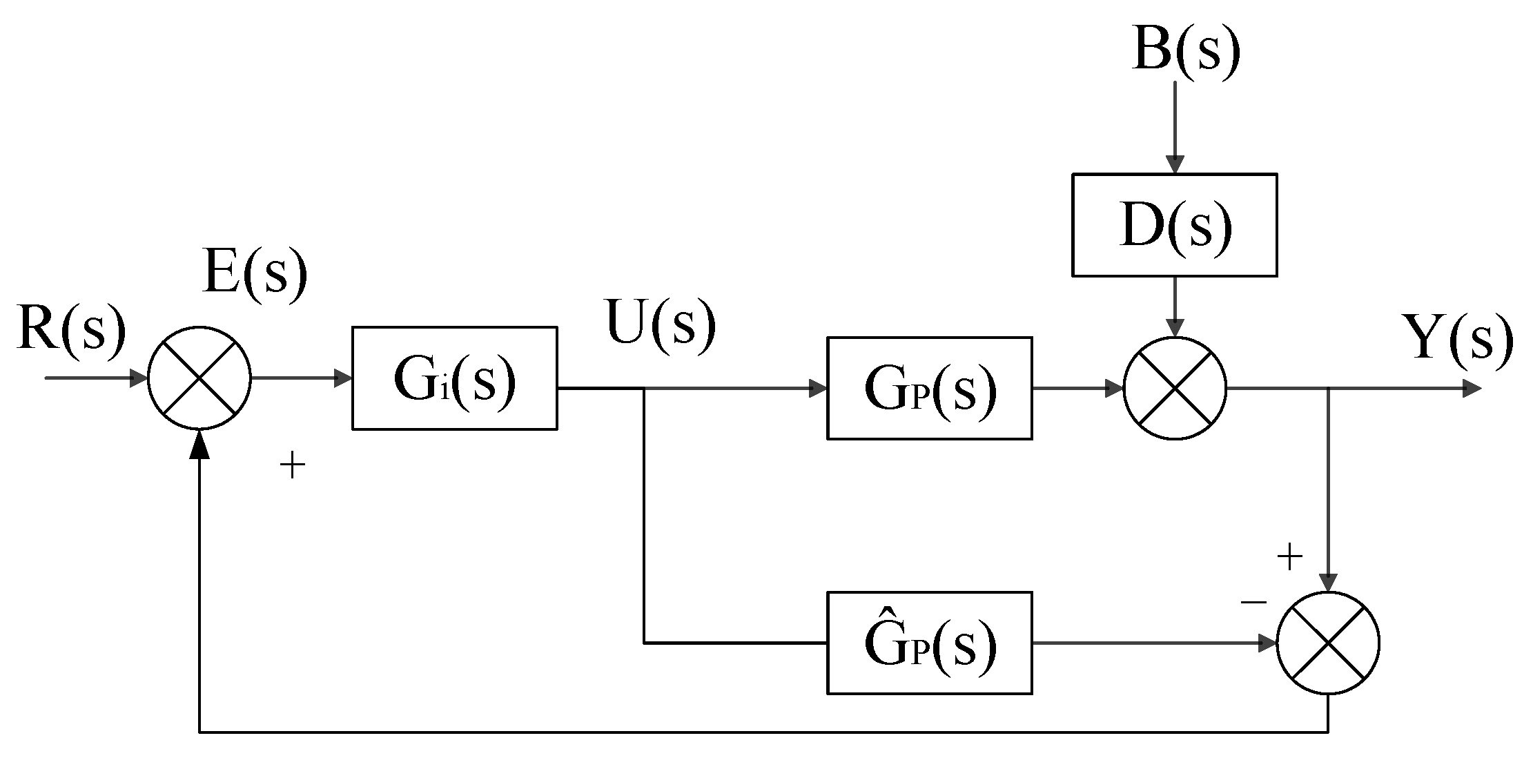
2.1. Internal Model Control

A block diagram of the internal mode control structure is shown in Figure 2. G i s is the controller transfer function, G p s is the object of control, G ^ p s is a mathematical model of the control channel, B s is a disturbance.
To use this controller, a first order filter is added to it, then [27]
G f s = T a s + 1 K a T f s + 1 .
Given the system step signal, the output is
U s = G f s R s = T a s + 1 K a T f s + 1 n 1 s = 1 K a 1 s + T a T f K a T f 1 s + 1 T f .
Performing Laplace inversions [28],
u t = 1 K a + T a T f K a T f e t T f .
If T a < T f , the control output shows a monotonically increasing trend and u achieves its maximum value. If T a > T f , then it can be found that
u 0 = 1 K a 1 + T a T f T f ,
u = 1 K a .

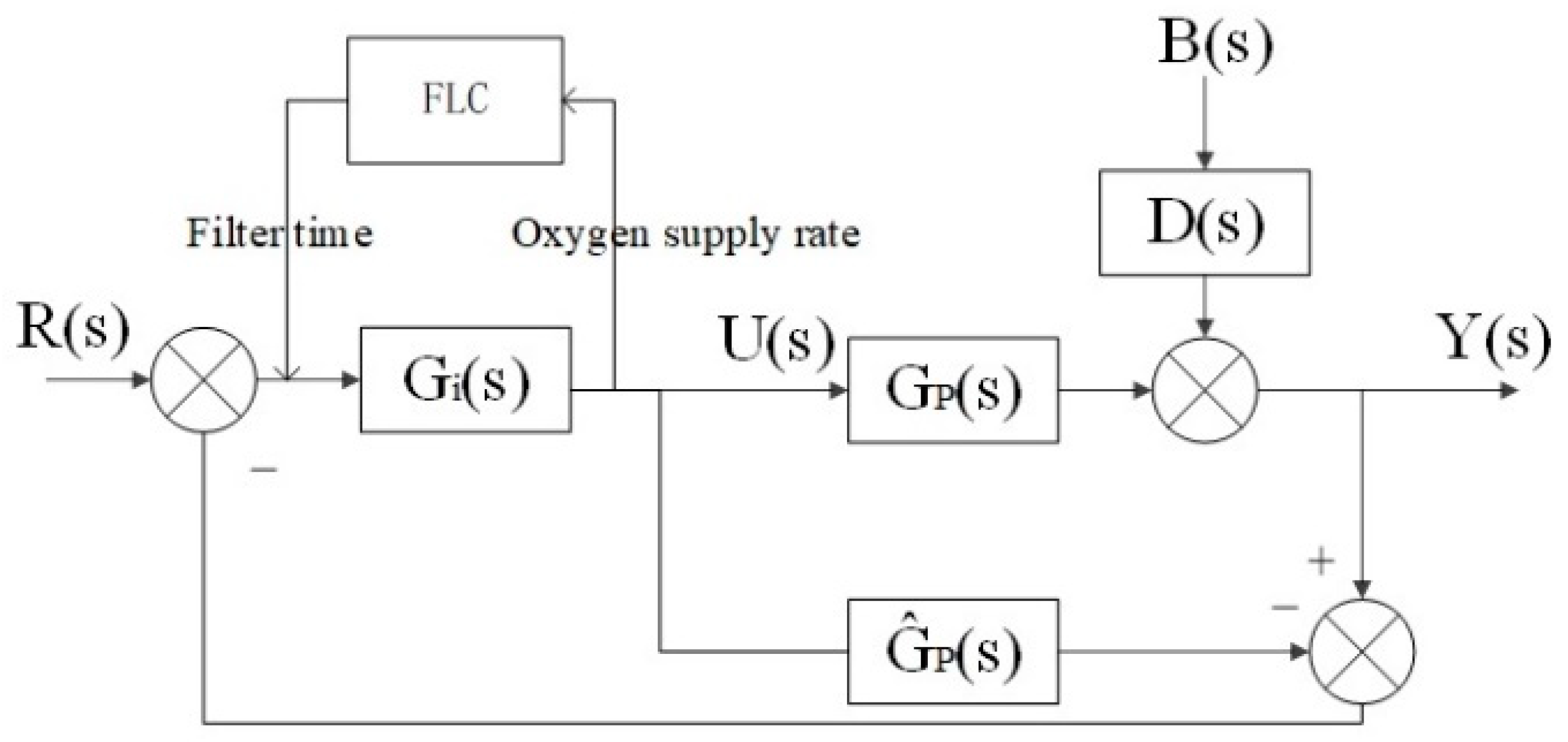
2.2. Adaptive Fuzzy Regulator

All signals of the control object under study in this paper are consistently bounded where the output quantity tracks the bounded reference signal [29] as a MISO system. The vector of its nth state variable can be defined as x = x 1 t , x n t T . The generalized state variable x ¯ i = x z d z j can be defined; then, the affiliation functions of the fuzzy sets P and N corresponding to the generalized state variable can be taken as
m P x ¯ i = e 1 2 x ¯ i k i 2 ;   m N x ¯ i = e 1 2 x ¯ i k i 2 .
The fuzzy rule is
R l : IF   x 1 d 11   is   F x 11   and   x 1 d 1 w j   is   F x 1 w 1   and   x 2 d 21   is   F x 21   and   x n d n w n   is   F x n w n THEN   y l = c F 11 + L + c F 1 w 1 + c F 21 + L + c F n w n .
In the formula, m = w i i = 1 n is the number of generalized state variables; w z z = 1 , K , n is the number of translations of x z , d z j z = 1 , , w z is the translation constant of x z ; k i is a constant.
In order to designin the adaptive fuzzy state feedback control for an internal mode controller, its filter time constant is adjusted to approximate the output to the maximum air supply.
Using this model, it is possible to introduce
y = A 0 + A 1 tanh K x x ¯ = θ T φ x ¯ .
In the formula, A 0 = 1 2 i = 1 m c P x i + c N x i + j = 1 q c P u i + c N u i ; A 1 = a 1 , K , a m , a i = c P i c N i 2 .

3. Metallurgical Modeling

3.1. Mechanistic Model Assumptions

The following assumptions were made for the process of smelting ferrochrome alloys in the AOD converter with side-top re-blowing.
  • Throughout the smelting process, the chemical reactions of all elements occur simultaneously in the converter and are able to reach a dynamic equilibrium in competition. During the stop-oxygen stirring process, the oxides stop reacting and reach a new equilibrium state [30].
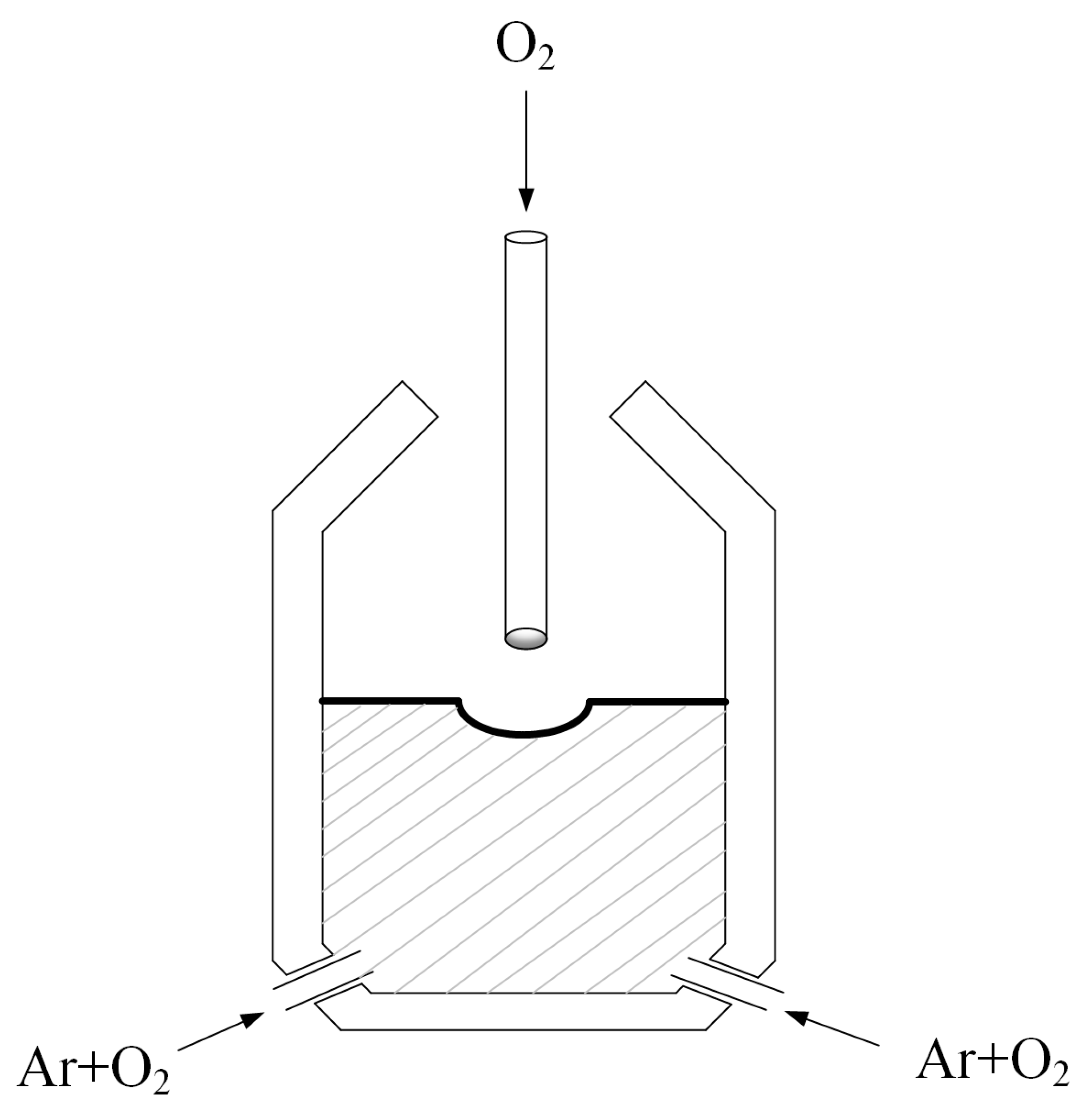
  • It is assumed that the entire smelting process is fully carried out. The oxygen blown into the AOD converter is not directly dissolved in the ferrochrome alloy. The CO produced will be changed to CO2 and discharged [31].
  • It is assumed that Fe is always involved in the oxidation reaction during the smelting process and that FeO is always involved in the reduction reaction to produce Fe. Both processes are always in dynamic equilibrium.
  • It is assumed that the relationship between the rate of oxygen blown in and the rate of oxidation during the smelting process is linear. Only C, Fe, Cr and Si are considered in the smelting process. Other elements are ignored.
  • The coupling between the rate of decarburization and the rate of temperature change is linear. The carbon content composition and temperature are continuously varied and uniformly distributed in the transient state.

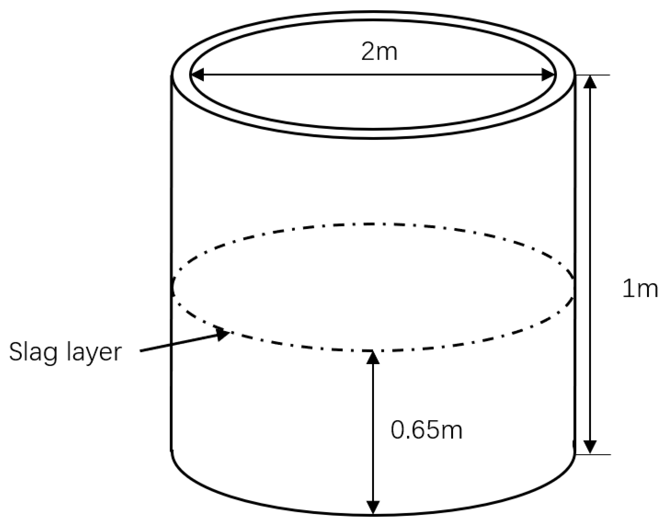
3.2. Smelting Model Building and Transfer Function Finding

3.2.1. Model of the Relationship between Decarbonization Rate and Oxygen Supply Rate

The main chemical reactions in the AOD converter are
3 C s + Cr 2 O 3 l = 3 CO g + 2 Cr l ,
3 Si s + 2 Cr 2 O 3 l = 3 SiO 2 s + 4 Cr l .
The Gibbs free energy for the two reactions occurring in the converter can be found from the following two equations:
Δ G C = Δ G C θ + R T ln P CO 3 a Cr 2 a C 3 a Cr 2 O 3 ,
Δ G Si = Δ G Si θ + R T ln a SiO 2 3 a Cr 4 a Si 3 a Cr 2 O 3 2 .
Then, the reaction rates of the two reactions can be found by the following equation:
W m 100 M C d % C d t = 2 η Q O 22,400 X C , O ,
W m 100 M Si · d % Si d t = 2 η Q O 22.4 · X Si , O .
In the formula, a i is the activity coefficient of element i , W m is the total mass of ferrochrome alloy, W s is the total slag mass, η is the oxygen utilization, Q O is the oxygenation rate.

3.2.2. Model of the Relationship between the Rate of Temperature Change and the Rate of Gas Supply

AOD converter temperature balance equation:
W m c m T + Q O d t ρ O c O T 0 + Q s u b d t ρ s u b c s u b T 0 + W s c s T + W m 100 d % C d t Δ H C d % Si d t Δ H Si d t = W m 1 + d % C d t + d % Si d t d t 100 c m T + d T + Q O 1 η d t ρ O c O T d + Q s u b d t ρ s u b c s u b T d + W m 100 d % C d t d t M CO M C c CO T d + q l o s s d t + W s W m d t 100 d % Si d t M SiO 2 M Si c s T + d T .
Rate of change of melt pool temperature:
d T d t = c s T M SiO 2 M Si d % Si d t c m T d % C d t + d % Si d t W m 100 Q O ρ O c O 1 η T d T 0 + Q s u b ρ s u b c s u b T d T 0 + q l o s s + c CO T d M CO M C d % C d t Δ H C d % C d t + Δ H S i d % Si d t 100 c m + 100 c s W s W m .
Oxidation reaction equation and enthalpy of melting calculation for each component element in the steel liquid:
C s + 0.5 O 2 g = CO g ,
Δ H C = Δ H CO Δ H C s 0.5 Δ H O = 11852 2.367 T g + 1.708 × 10 4 T g 2 + 3.835 × 10 3 T g ,
Si s + O 2 g = SiO 2 s ,
Δ H Si = Δ H SiO 2 Δ H Si s Δ H O = 30 , 658 2.15 T + 1.45 × 10 4 T 2 .
In the formula, Q s u b is the inert gas supply rate, Δ H i is the enthalpy of melting of component element I; T is the steel temperature; T 0 is the exhaust gas temperature, T d is the initial temperature of the blown-in gas, ρ i is the density of i , c i is the specific heat capacity of i , M i is the molar mass of i .
As the temperature inside the AOD converter is much greater than the temperature outside the converter, the heat dissipation can be seen as only the converter dissipating to the outside. The smelting process can therefore be seen as a one-dimensional steady-state heat transfer process. The bottom lance structure of the AOD converter has a small area. Therefore, the converter body is considered as a single barrel wall, as shown in the structure in Figure 3. The slag surface is used as a dividing line to divide the AOD converter into two parts, the upper and lower part. The upper part mainly contains the gas inside. The lower part of the converter contains mainly liquid ferrochrome alloy. The heat dissipation models for the two parts are calculated separately and added together. The temperature loss model of the AOD converter body can be obtained. This is what is shown in Equation (23).
Heat loss in upper and lower parts:
Φ 1 = A 1 λ 1 δ ( T d T 0 ) ,
Φ 2 = A 2 λ 2 δ ( T T 0 ) .
From the converter size data, the total heat loss can be calculated:
q l o s s = Φ 1 + Φ 2 = 108.81 T 20,446.28 .
In the formula, A is the heat transfer part area; λ is the thermal conductivity; δ is the thickness of heat transfer layer.

3.3. Mechanistic Model Transfer Function Finding

3.3.1. Carbon Content and Oxygen Supply Rate Transfer Function

The proportion of oxygen partitioned during the oxidation reaction of element C, Equation (11), is then brought into Equation (12) to solve for the decarbonization rate.
The relationship between carbon content and oxygen supply rate is calculated as follows:
d % C d t = 1.52 × 10 8 Q O .
Applying the Laplace transform to Equation (24), the mathematical model of the mechanism is obtained as
G 1 s = C s Q s = 1.52 × 10 8 s .

3.3.2. Temperature and Gas Supply Rate Transfer Function

In the process of calculating the temperature and oxygen supply rate and inert gas supply rate, Equation (15) needs to be deformed to obtain Equation (16), which is the same as the model for carbon content. The oxidation Equations (18) and (20) for each element in the steel are used to calculate the enthalpy of melting of each element during the reaction, i.e., Equations (21) and (22), and finally Equations (13), (14) and (21)–(23) are brought into Equation (16).
Calculating Equation (25), the relationship between the rate of temperature change and the rate of oxygen supply can be obtained as
d T d t = 7.89 × 10 8 × Q O + 2.03 × 10 10 × T × Q O 2.33 × 10 5 × T 1.54 × 10 7 Q s u b .

4. Controller Design

Using the structural symmetry of the generalized fuzzy hyperbolic tangent model mentioned in Section 2.2, the structural identification problem can be reduced to determining the number of fuzzy variables, so the linguistic information can be fully utilized to constitute a complete fuzzy rule and model. Considering the oxygen supply rate in the internal mode control as the input and the internal mode control filter time constant as the output, the fuzzy control can be considered as a SISO system, and then the control rule can be constructed.
x n = f x , x ( n ) , L , x n 1 + g x , x ( n ) , L , x n 1 u + d y = x .
In the formula, f , g are unknown nonlinear functions; u k , R , y ( k ) , R are the input and output variables of the system, respectively; X = x , x n , L , x n 1 T = x 1 , L , x n T , R n are state vectors; d , R are a bounded uncertainty term containing external disturbances. The control objective is to design a direct fuzzy adaptive control law so that the output filter time constant tracks the bounded signal, assuming that the output quantity has 1~ n 1 -order derivatives. Defining e = y m y as the following error of the system, it is possible to define Y m = y m , y m ( n ) , L , y m ( n 1 ) T , E = Y m X .
The system can be constructed and represented as:\
X ( n ) = A X + B f ( x ) + g ( X ) u + d y = C T X .
Among them,
A = 0 1 L 0 M L 1 M 0 L 0 1 0 0 0 0   B = 0 M 0 1   C = 1 0 M 0 .
Then, the control system can be set up as shown in Figure 4 below.

5. Simulation and Analysis

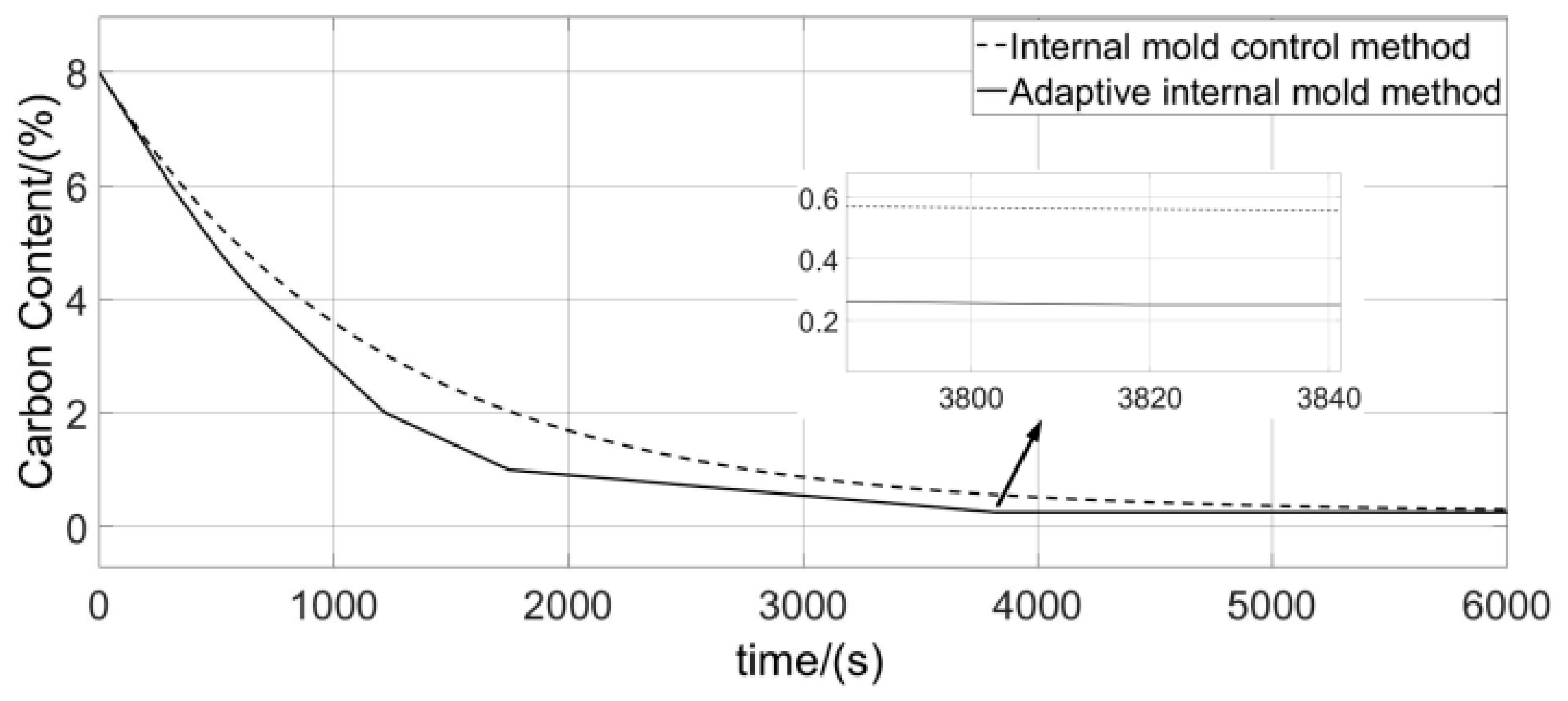
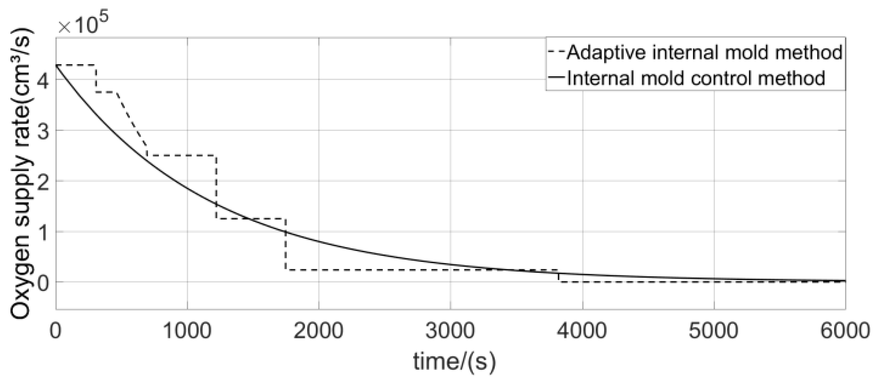
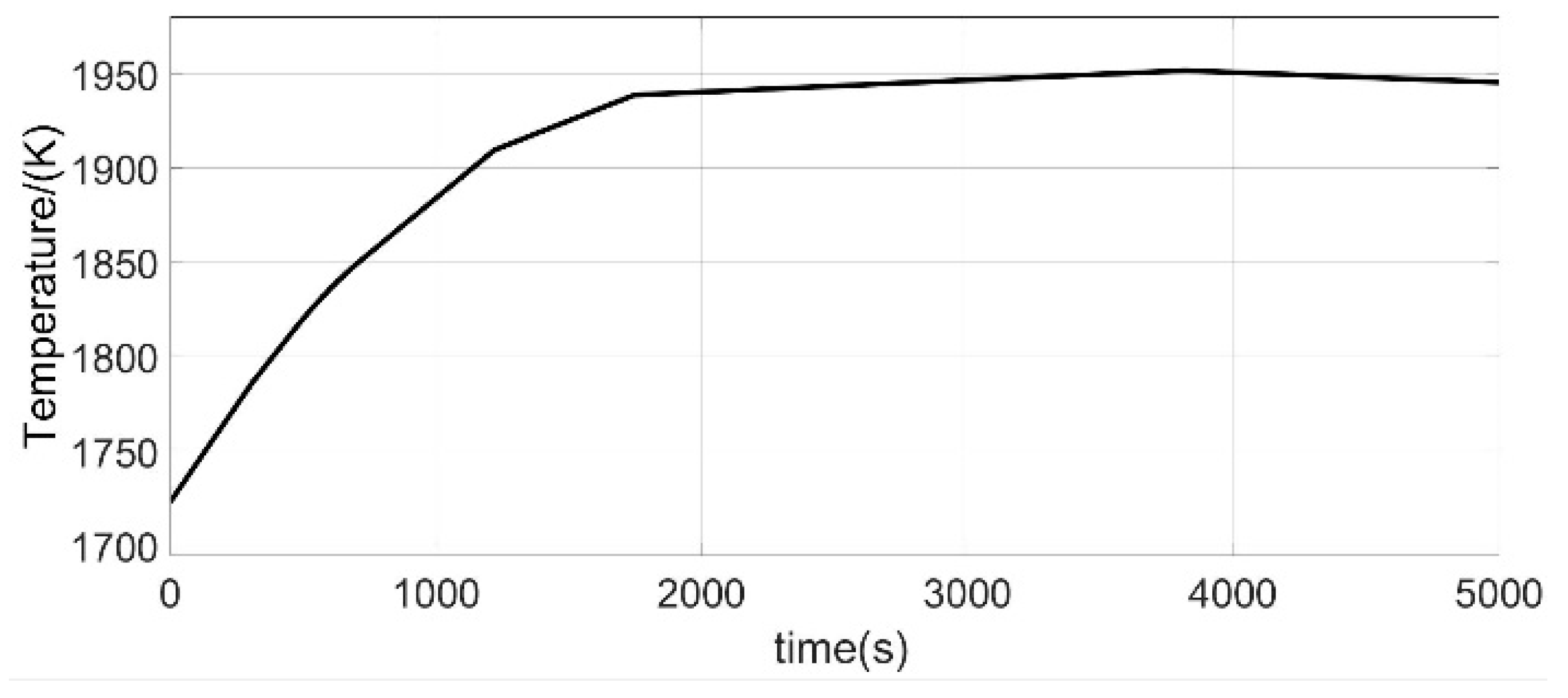
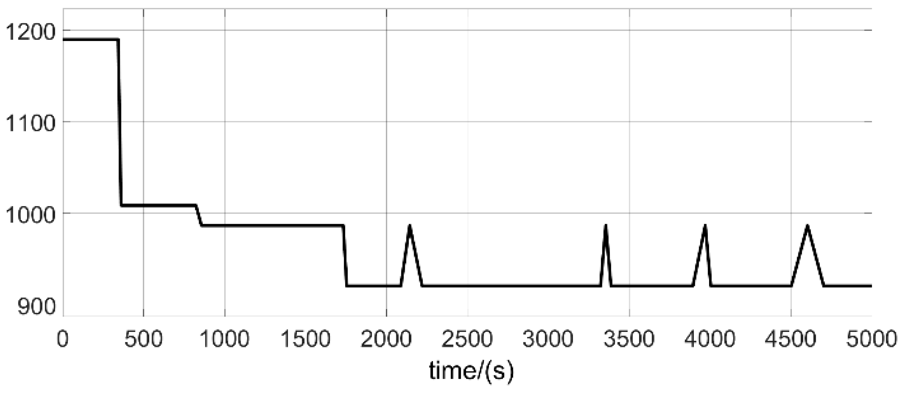
5.1. Simulation Design and Curves

In order to be able to verify the effectiveness of the method, simulation experiments were first carried out. The simulation experiments were carried out in Matlab 2013b software using the mathematical model described above. In order to meet the actual smelting conditions as closely as possible, a series of constraints were set for the simulation experiments. The initial carbon content of the high-carbon ferrochrome alloy was set at 8% and the temperature was set at 1673 K. This was consistent with the actual situation.
According to the above, if the converter temperature is too high in actual smelting, it can affect the life of the equipment. Then, a temperature constraint should also be included in the simulation. The converter temperature should be kept below 1950 K for the entire smelting process and is limited by the actual amount of blowing into the AOD lance. A similar constraint should be added to the simulation. The data in Table 1 show the AOD gas supply volume data. The current maximum gas supply for the AOD converter plant is 1600 m3/h, i.e., 444,444 cm3/s. The maximum gas supply can be used continuously during decarburization of the raw material carbon content of 8% to 1%. In the later stages of the smelting process, in order to avoid wasting oxygen and argon, only the bottom lance was used for the gas supply. In this case, the maximum gas supply was 200 m3/h, i.e., 55,555 cm3/s. Constraints were added in accordance with this actual situation. After adding the constraint, the simulation was carried out with the objective of smelting a low-carbon ferrochrome with a carbon content of 0.25%. The simulation results in Figure 4, Figure 5 and Figure 6 were obtained.
The simulated smelting time is shown in Figure 5. The solid line in the diagram shows the improved method used in this paper. The dashed line in the figure shows the use of the normal internal mold method. According to the data in the figure, using the improved method in this paper requires 3840 s of time. Using the normal method, it is approximately 5200 s. The calculation provides a time improvement of approximately 26.15%. However, this is a theoretical figure. The reason for the time improvement is mainly due to the feedback adjustment of the smelting parameters by the improved method based on the output volume. The general method is based on data or smelting experience for the development of the smelting strategy. This is the major difference between the two.
The control process is illustrated in Figure 6. This is mainly reflected in the control of the oxygen supply rate. The dashed line shows the method used in this paper. The solid line shows the general method. Compared to a control strategy with a fixed filter time constant, depending on the smelting section, it is possible to increase not only the smelting time. At the same time, the converter temperature is used as one of the influencing factors. This makes the control of the smelting process more efficient.
Figure 7 below shows the variation in smelting temperature using the method in the text. Since temperature is added as an influencing factor to the control strategy, the temperature of the entire smelting process does not exceed 1950 K. This allows the AOD converter to be used more often.
Figure 8 illustrates the filter time constant adjustment process after applying the method in this paper. Based on the feedback from the smelting, the filter time constant is adjusted according to the set control strategy.

5.2. Analysis of Measured Data

The main experimental considerations are decarburization data and converter temperature data. The carbon content in the liquid high-carbon ferrochrome alloy is the main object of control.
Smelting was carried out using a liquid high-carbon ferrochrome alloy with an initial carbon content of 8%. The composition of the high-carbon ferrochrome used is shown in Table 2 below. Depending on the elemental Cr content, there are two types of product. One is a product with approximately 65% Cr and the other is a product with approximately 55% Cr. Other elements include carbon, sulfur, silicon and phosphorus. Element S is <0.02%, element P is <0.02% and element Si is about 2% to 4%. These three elements make up a low proportion, and their influence can be ignored in this experiment. A low-carbon ferrochrome alloy product with a carbon content of less than 0.25% should be obtained at the end of the smelting. The converter temperature should be kept below 1950 K during smelting in order to allow the AOD converter to serve more often. The composition is shown in Table 3.
The actual smelting of 5 t of AOD was carried out at the partner smelter, Jilin Iron and Steel Works. Experimental data from smelting using conventional methods were already available prior to the experiment. Five sets of better results were selected. The first converter had an experimental carbon content of 0.25%, a maximum converter temperature of 1985 K and a smelting time of 84.9 min. The second converter had a carbon content of 0.25%, a maximum converter temperature of 1952 K and a smelting time of 84.1 min. The third converter had a carbon content of 0.25%, a maximum converter temperature of 1965 K and a smelting time of 81.3 min. The fourth converter had a carbon content of 0.25%, a maximum converter temperature of 1975 K and a duration of 88.3 min. The fifth converter had a maximum converter temperature of 1997 K with a carbon content of 0.25% and a smelting time of 88.7 min.
The actual smelting was carried out in the same circumstances using the improved method in this paper. Smelting was divided into five stages. Decarburization experiments were also carried out using a liquid high-carbon ferrochrome alloy feedstock with a carbon content of 8%. The data recorded included the smelting time and the maximum temperature that could be reached in the converter during the smelting process. At the end of the smelting, the finished product was tested for conformity using a composition analyzer. The test data are presented in Table 4. The first converter had an experimental carbon content of 0.25%, a maximum converter temperature of 1923 K and a smelting time of 74.6 min. The second converter had a carbon content of 0.25%, a maximum converter temperature of 1906 K and a smelting time of 73.5 min. The third converter had a carbon content of 0.25%, a maximum converter temperature of 1910 K and a smelting time of 73.9 min. The fourth converter had a carbon content of 0.25%, a maximum converter temperature of 1889 K and a duration of 77.2 min. The fifth converter had a maximum converter temperature of 1925 K with a carbon content of 0.25% and a smelting time of 72.3 min. This can be derived by calculation. The average smelting time is approximately 74.3 min.
Data calculations were performed for the general method above. The average time used for smelting using the general method was 85.2 min. Analysis was carried out, as shown in Table 4. The average smelting time is approximately 74.3 min when using the method in this paper. It can be concluded that the method proposed in this paper is able to reduce the smelting time by approximately 12.79%. This contributes to an increase in production efficiency.

6. Conclusions

This paper investigates the application of an internal mode controller to the smelting of ferrochrome alloys. The design provides the oxygen supply rate as the system output. The rate of carbon content change and temperature are the outputs. A model is built to obtain a transfer function for the relationship between the input quantity and the output quantity. On this basis, combined with the actual engineering requirements, an internal mode control system containing actuator saturation adaptive parameters is established. The method is able to exploit the advantages of the internal-mode controller. At the same time, the method can effectively overcome the shortcomings of the long smelting time after the application of the internal mode controller within the temperature range allowed. The improvement of the internal mode control method is followed by actual smelting. A comparison of the data shows that the improved method is able to reduce the smelting time by 12.79%.

Author Contributions

Conceptualization, N.Q. and S.H.; methodology, N.Q.; software, N.Q.; validation, N.Q., S.H. and Y.W.; formal analysis, N.Q.; investigation, N.Q.; resources, N.Q. and S.H.; data curation, Y.W.; writing—original draft preparation, N.Q.; writing—review and editing, N.Q., W.Y. and S.H.; visualization, N.Q.; supervision, W.Y. and S.H.; project administration, N.Q., W.Y. and S.H.; funding acquisition, W.Y. and S.H. All authors have read and agreed to the published version of the manuscript.

Funding

This research was funded by [Jilin Provincial Science and Technology Department] grant number [20210203147SF] And The APC was funded by [School of Medical Information, Changchun University of Chinese Medicine].

Data Availability Statement

The data that supports the findings of this study are available.

Acknowledgments

This work was supported by Development Plan Project of Jilin Provincial Science and Technology Department (20210203147SF). The authors declare no competing financial interests.

Conflicts of Interest

The authors have no conflict to disclose.

References

  1. Kulkarni, V.R.; Jagannath, N.; Dabhade, V.V. Effect of chromium addition on properties of sinter-forged Fe–Cu–C alloy steel. Int. J. Mod. Phys. B 2018, 32, 1840040. [Google Scholar] [CrossRef]
  2. Dwarapudi, S.; Tathavadkar, V.; Rao, B.C.; Kumar, T.K.S.; Ghosh, T.K.; Denys, M. Development of Cold Bonded Chromite Pellets for Ferrochrome Production in Submerged Arc Furnace. ISIJ Int. 2013, 53, 533–539. [Google Scholar] [CrossRef]
  3. Peng, C.; Fan, J.F. Rotary hearth furnace process development in Baosteel. Iron Steel 2019, 54, 97–100. [Google Scholar] [CrossRef]
  4. Wei, T.; Shen, Q.H.; Zhan, H.W. The Development Thinking of Lance Life of Top-blown Melting Furnace. Sci. Technol. Eng. 2009, 9, 5778–5782+5791. [Google Scholar] [CrossRef]
  5. Byrne, G. Duplex Stainless Steels—Alloys for the 21st Century. Metals 2021, 11, 836. [Google Scholar] [CrossRef]
  6. Liu, Z.; Jones, P.T.; Kendall, M.; Blanpain, B.; Guo, M. On the CO Desorption and Absorption in Liquid Low-carbon Steel. ISIJ Int. 2021, 61, 510. [Google Scholar] [CrossRef]
  7. Kärnä, A.; Visuri, V.-V.; Heikkinen, E.-P.; Sulasalmi, P.; Torvinen, P.; Koskinen, J.; Fabritius, T. Numerical Modeling of Argon-Oxygen Decarburization Slag Cooling. Steel Res. Int. 2020, 91, 1134–1141. [Google Scholar] [CrossRef]
  8. Järvinen, M.; Visuri, V.V.; Heikkinen, E.P.; Kärnä, A.; Sulasalmi, P.; De Blasio, C.; Fabritius, T. Law of Mass Action Based Kinetic Approach for the Modelling of Parallel Mass Transfer Limited Reactions: Application to Metallurgical Systems. ISIJ Int. 2016, 56, 1543–1552. [Google Scholar] [CrossRef]
  9. Shi, G.M.; Wei, J.H.; Zhu, H.L.; Shu, J.H.; Jiang, Q.Y.; Chi, H.B. Preliminary Investigation of Mathematical Modeling of Stainless Steelmaking in an AOD Converter: Application of the Model and Results. Steel Res. Int. 2016, 78, 311–317. [Google Scholar] [CrossRef]
  10. Illarionov, A.G.; Kosmatskii, Y.I.; Filyaeva, E.A.; Vodolazskii, F.V.; Barannikova, N.A. Experimental Determination of Temperature Parameters for Evaluating the Possibility of Manufacturing Alloy Ti-3Al-2.5V Hot-Extruded Tubes. Metallurgist 2017, 60, 983–988. [Google Scholar] [CrossRef]
  11. Wei, J.H.; Li, Y. Study on Mathematical Modeling of Combined Top and Bottom Blowing VOD Refining Process of Stainless Steel. Steel Res. Int. 2015, 86, 189–211. [Google Scholar] [CrossRef]
  12. Wuppermann, C.; Rückert, A.; Pfeifer, H.; Odenthal, H.J. Physical and Mathematical Modeling of the Vessel Oscillation in the AOD Process. ISIJ Int. 2013, 53, 441–449. [Google Scholar] [CrossRef]
  13. Ternstedt, P.; Ni, P.; Lundqvist, N.; Tilliander, A.; Jönsson, P.G. A physical modelling study to determine the influence of slag on the fluid flow in the AOD converter process. Ironmak. Steelmak. 2018, 45, 944–950. [Google Scholar] [CrossRef]
  14. You, J.; Wang, S.C.; Li, X.S.; Han, Y.P. Determination of blowing end point of oxygen top blown converter by flame texture analysis of converter mouth. J. Beijing Univ. Sci. Technol. 2000, 6, 524–528. [Google Scholar] [CrossRef]
  15. Fei, H.; Zhang, L. Prediction model of end-point phosphorus content in BOF steelmaking process based on PCA and BP neural network. J. Process Control 2018, 66, 51–58. [Google Scholar] [CrossRef]
  16. Zhou, H.; Zhang, H.; Yang, C. Hybrid Model Based Intelligent Optimization of Ironmaking Process. IEEE Trans. Ind. Electron. 2019, 67, 2469–2479. [Google Scholar] [CrossRef]
  17. Yu, F.-P.; Lin, J.-J.; Lin, X.-M.; Li, L. Dual pulse laser induced spectroscopy combined with multivariate GA-BP-ANN detection of C element in alloy steel. Spectrosc. Spectr. Anal. 2022, 42, 197–202. [Google Scholar] [CrossRef]
  18. Li, L.; Niu, H.-F.; Lin, J.-J.; Che, C.-J.; Lin, X.-M. Quantitative Analysis of Carbon Elements in Collinear DP-LIBS Low Carbon Alloy Steel. Spectrosc. Spectr. Anal. 2018, 38, 2951–2956. [Google Scholar] [CrossRef]
  19. Chen, G.-H.; Zhang, D.-J.; Lin, X.-M. AOD furnace bottom gun infrared colorimetric temperature measurement system based on gray temperature compensation model. Metall. Ind. Autom. 2013, 37, 62–67. [Google Scholar] [CrossRef]
  20. Wei, J.H. Physical and Mathematical Modeling of the Argon-Oxygen Decarburization Refining Process of Stainless Steel. J. Shanghai Univ. 2002, 1, 1–23. [Google Scholar] [CrossRef]
  21. Wei, J.H.; Zeng, L. Numerical Simulation of Fluid Flow in Bath during Combined Top and Bottom Blowing VOD Refining Process of Stainless Steel. Steel Res. Int. 2012, 83, 1053–1070. [Google Scholar] [CrossRef]
  22. Wei, J.H.; Yuan, H.E.; Shi, G.M. Mathematical Modeling of Fluid Flow in an AOD Converter Bath under Conditions of Combined Side and Top Blowing: Application of the Model to Combined Side and Top Blowing Process and Results. Chin. J. Process Eng. 2011, 11, 40–43. [Google Scholar] [CrossRef]
  23. Wei, J.H.; Zhu, H.L.; Chi, H.B.; Wang, H.J. Physical Modeling Study on Combined Side and Top Blowing AOD Refining Process of Stainless Steel: Fluid Mixing Characteristics in Bath. ISIJ Int. 2010, 50, 26–34. [Google Scholar] [CrossRef]
  24. Li, B.; Wei, J.H.; Jiang, X. A simulating investigation into the characteristics of the mass transfer between molten steel and particles in the 150 t RH-IJ refining. Baosteel Technol. Res. 2010, 4, 6. [Google Scholar] [CrossRef]
  25. Ma, H. Mathematical Model and Control Strategy of Argon-Oxygen Refining Low-Carbon Ferrochrome Production Process; University of Chinese Academy of Sciences: Beijing, China, 2011. [Google Scholar]
  26. Wei, B.K.; You, W.; Guan, C.J. Endpoint Predictive Control System for Argon-Oxygen Refining of Low Carbon Ferrochrome Based on Internal Model Control. Metall. Ind. Autom. 2020, 44, 55–59+66. [Google Scholar] [CrossRef]
  27. Moon, E.J.; Choi, Y.C. Development of carbon-capture binder using stainless steel argon oxygen decarburization slag activated by carbonation. J. Clean. Prod. 2018, 180, 642–654. [Google Scholar] [CrossRef]
  28. Song, Z.; Ersson, M.; Jnsson, P. A Study of Post-Combustion in an AOD Flue. Steel Res. Int. 2014, 85, 1173–1184. [Google Scholar] [CrossRef]
  29. Rout, B.K.; Brooks, G.; Akbar Rhamdhani, M.; Li, Z.; Schrama, F.N.; van der Knoop, W. Dynamic Model of Basic Oxygen Steelmaking Process Based on Multizone Reaction Kinetics: Modeling of Manganese Removal. Metall. Mater. Trans. B 2018, 49, 2191–2208. [Google Scholar] [CrossRef]
  30. Gao, C.; Shen, M.G.; Liu, X.P.; Zhao, N.N.; Chu, M.X. End-point dynamic control of basic oxygen furnace steelmaking based on improved unconstrained twin support vector regression. J. Iron Steel Res. Int. 2020, 27, 42–54. [Google Scholar] [CrossRef]
  31. Wu, S.; Xu, A. Calculation Method of Energy Saving in Process Engineering: A Case Study of Iron and Steel Production Process. Energies 2021, 14, 5756. [Google Scholar] [CrossRef]
Figure 1. Diagram of AOD blowing argon–oxygen gas.
Processes 11 01461 g001
Figure 2. Diagram of the internal model control structure.
Processes 11 01461 g002
Figure 3. Single-layer cylinder wall assumption schematic.
Processes 11 01461 g003
Figure 4. Adaptive parameter internal mode controller.
Processes 11 01461 g004
Figure 5. Carbon content change curve under adaptive method and internal model method.
Processes 11 01461 g005
Figure 6. Oxygen supply rate curve under adaptive method and internal model method.
Processes 11 01461 g006
Figure 7. Temperature change curve.
Processes 11 01461 g007
Figure 8. Oxygen supply rate curve under adaptive method and internal model method.
Processes 11 01461 g008
Table 1. Oxygen supply rate saturation constraint table.
Carbon ContentOxygenation Rate
8–1%444,444 cm3/s
1–0.25%55,555 cm3/s
Table 2. High-carbon ferrochrome chemical composition.
ComponentCrCSPSi
Content>55% or >65%C < 8%<0.02%<0.03%2~4%
Table 3. Low-carbon ferrochrome chemical composition.
ComponentCrCSPSi
Content60~65%C < 0.25%<0.02%<0.03%2~4%
Table 4. Improved control method actual smelting data.
Serial No.End Point Carbon ContentEnd Point TemperatureTime
1#0.25%1923 K74.6 min
2#0.25%1906 K73.5 min
3#0.25%1910 K73.9 min
4#0.25%1889 K77.2 min
5#0.25%1925 K72.3 min
Disclaimer/Publisher’s Note: The statements, opinions and data contained in all publications are solely those of the individual author(s) and contributor(s) and not of MDPI and/or the editor(s). MDPI and/or the editor(s) disclaim responsibility for any injury to people or property resulting from any ideas, methods, instructions or products referred to in the content.

