Article

Applying a Combination of Cutting-Edge Industry 4.0 Processes towards Fabricating a Customized Component

by
Antreas Kantaros
1,*,
Evangelos Soulis
1,
Theodore Ganetsos
1 and
Florian Ion Tiberiu Petrescu
2,*
1
Department of Industrial Design and Production Engineering, University of West Attica, 12244 Athens, Greece
2
Theory of Mechanisms and Robots Department, Faculty of Industrial Engineering and Robotics, Bucharest Polytechnic University, 060042 Bucharest, Romania
*
Authors to whom correspondence should be addressed.
Processes 2023, 11(5), 1385; https://doi.org/10.3390/pr11051385
Submission received: 12 April 2023 / Revised: 25 April 2023 / Accepted: 26 April 2023 / Published: 4 May 2023

Abstract

:
3D scanning, 3D printing, and CAD design software are considered important tools in Industry 4.0 product development processes. Each one of them has seen widespread use in a variety of scientific and commercial fields. This work aims to depict the added value of their combined use in a proposed workflow where a customized product needs to be developed. More specifically, the geometry of an existing physical item’s geometry needs to be defined in order to fabricate and seamlessly integrate an additional component. In this instance, a 3D scanning technique was used to digitize an e-bike’s frame geometry. This was essential for creating a peripheral component (in this case, a rear rack) that would be integrated into the frame of the bicycle. In lieu of just developing a tail rack from scratch, a CAD generative design process was chosen in order to produce a design that favored both light weight and optimal mechanical behaviors. FDM 3D printing was utilized to build the final design using ABS-CF10 materials, which, although being a thermoplastic ABS-based material, was introduced as a metal replacement for lighter and more ergonomic component production. Consequently, the component was manufactured in this manner and successfully mounted onto the frame of the e-bike. The proposed process is not limited to the manufacturing of this component, but may be used in the future for the fabrication of additional peripheral components and tooling.

1. Introduction

The demand for customized and tailormade products in very small batches (or even sometimes as single components) is not time and cost effective when traditional manufacturing techniques are being used. For example, the injection molding technique needs the presence of the specified mold (that is dependent on the shape of the component and any alterations on the design require the fabrication of a new mold) that takes weeks to be fabricated and its cost is high [1]. Therefore, its use for single components and small batches has many drawbacks. A CNC milling device could be an alternative for customized and tailormade products in very small batches (or even sometimes as single components). However, in this technique, a high percentage of material waste is created due to its subtractive modus operandi and a high user expertise is also required [2]. In conclusion, while both methods have the ability to create high quality parts, they have many restrictions for their widespread adoption by single users or SMEs (small- and medium-sized enterprises).
In order to address the aforementioned limitations, a new construction method was introduced for prototyping. This method integrates the construction of 3D solid objects from a digital CAD file. This is achieved by using the Additive Manufacturing (“AM”) method whereby the deposition of successive layers of material leads to the final creation of a real physical object. Each layer can be visualized as a thin horizontal cross-section of the final product. This technology is also known as “3D printing” and allows for a quick and easy transition from a CAD design to the manufacturing of physical objects. Its contribution to bridging the gap between product design and prototyping time is enormous, hence the term “rapid”. This technology is often described as “the third industrial revolution” [3,4] and through a series of technical advances can nowadays also be described as a method of manufacturing end-use products [5,6].
Modern additive manufacturing dates back to the 1980s with the first mention of stereolithography. Technological innovations in home computing and the increased availability of industrial lasers led to the development of many new AM processes in the late 1980s and 1990s [7]. Some of the processes considered AM processes are Selective Laser Sintering (SLS), Fused Deposition Modeling (FDM), and Stereolithography (SLA). In the following years, AM processes were used in many fields such as aerospace, medical sciences, energy production, automotive production, and consumer goods [8,9,10,11,12,13,14]. Figure 1 depicts a desktop FFF (Fused Filament Fabrication) 3D printer.
On the other hand, the issue of obtaining accurate 3D data from real-world objects, especially when they are more complex than simple geometric shapes such as spheres or cubes, is a major challenge. The problem has been difficult to solve in the past and approaches have been time consuming. The development of powerful computing systems and digital measuring devices has resulted in an ever-evolving market for 3D scanners. These systems allow the capture of geometric and color information carried by objects within a minimum time frame. The principles guiding their operation are based on the geometric axioms and functions that will be discussed in more detail below. This ability is of paramount importance in cases where a customized component needs to be fabricated, because the exact topological features of the installation site can be acquired swiftly. A 3D scanner can be defined as any device capable of automatically collecting 3D coordinates from a given area on the surface of an object [15,16,17]. This method is usually performed at high speed, with hundreds or even thousands of sample points collected per second. This allows a real-time scanning process that can also distinguish between different colors and textures. The mode of use of such a device may be fixed in a particular location, on a classic, photography tripod or on a similar type of transportable base. One of the main reasons why 3D scanners are growing in popularity is because of the tremendous improvement in computer hardware for creating real-time 3D graphics. The ability to efficiently handle complex 3D geometries on low-cost platforms is useful for visualizing detailed and accurate 3D models generated by scanning devices [15]. The goal of all studies is to minimize the time required to capture objects while maintaining high fidelity of results. Figure 2 depicts a handheld 3D scanner.
Additionally, CAD (Computer Aided Design) software packages offer the ability to design virtually any shape and geometric form for users and enterprises. The final generated CAD file can be directly inserted to the 3D printer’s slicing software and, thus, fabricate the final custom object as mentioned earlier. An evolution of this procedure, is the so called “generative design”. Generative design can be described as a technique of design experimentation. Designers or engineers enter design objectives into the generative design program together with variables like performance or space requirements, materials, manufacturing processes, and cost restrictions. The program swiftly generates design alternatives by exploring every variation of a potential solution. With each iteration, it tests new ideas and learns when the design performs better and when it does not. At the end of the process the program presents the optimal solution [18,19,20,21,22,23,24,25,26,27,28,29,30,31,32,33,34,35,36].
In this context, the use of CAD design software along with generative design characteristics and 3D printing techniques can immensely contribute towards fabricating customized, tailormade components that are able to meet highly specified operating demands. The simultaneous use of 3D scanning techniques in this procedure allows the swift digitization of already existing items, that might be difficult or time consuming to design. In this work, the 3D scanning of a complete bicycle assembly allows for the swift digitization of the bicycle and also allows the seamless design of peripheral components that will be attached on specified spots of the bicycle. In this way, the design process is accelerated and the incorporation of the peripheral components is flawless, since the bicycle and peripheral components are being viewed as a digital assembly of components with guaranteed functionality that can be checked manually.
Bicycles are a quite common means of transportation. The number of bicycles on the planet today is estimated to be over one billion [37]. A particular characteristic of bicycles is their ability to meet a number of different requirements, such as mobility, sport, and leisure. In its classic form, the bicycle consists of two wheels, one behind the other, connected by a metal frame. Other key parts of a typical bicycle are the handlebars, the saddle, the transmission, and the brakes. A number of accessories are used as additional peripheral components, considered essential for the functionality of the bicycle.
Several cities around the world are promoting the use of bicycles as a basic means of transport. In Europe, Amsterdam, Copenhagen, and Barcelona are typical examples. The creation of a network of cycle lanes (cycle paths) and parking spaces for bicycles are key indicators of facilitating the use of bicycles. Cycling enthusiasts believe that cycling can be the solution to the severe transport problems that characterize most large cities. This tendency fits well in the concept of “micro-mobility” which is a new trend that is changing the lives of city dwellers. Increased traffic, congestion, and ecological awareness are prompting more and more people to turn to micro-mobility, which, as things stand, has become a regular feature of our daily lives. Their main arguments are that cycling does not cause traffic congestion, requires minimal parking space, can be used off-road, and does not pollute the environment in any way [37,38,39,40,41,42,43,44,45,46,47,48,49,50,51].
According to a McKinsey survey of 6000 citizens aged 18–65 who use forms of micro-mobility at least once a day, almost 70% of citizens said they would like to use a bicycle, moped (electric or traditional), or electric scooter for their daily commute, either exclusively in the urban fabric of the city or in combination with their car. In Italy, 49% of citizens preferred cycling for their daily commute, while 42% of French people shared the same choice [52]. An electric scooter was chosen by 13% of Italians, 18% of French people, and 13% of Germans and English people. The survey results show that an increasing number of people are willing to adopt micro-mobility as their preferred means of transport from home to work, as long as the appropriate infrastructure is in place, as well as appropriate education by users (e.g., helmets). The more micro-mobility increases, the less pressure there will be on the roads and the lower the emission rates. The willingness of consumers to use micro-mobility devices varies considerably from country to country. The willingness to use micro-mobility is strongest in countries with a long tradition, for example, in China (86%) which has always used and still uses bicycles and Italy (81%). In contrast, in the US, where cars have dominated and continue to dominate, micro-mobility is at low levels. Finally, electric bicycles offer greater autonomy and are easier to store than mopeds, which are particularly popular in China. Public transport can also play an important role in increasing forms of micro-mobility, as it can encourage the use of micro-mobility means by providing transport modes for these means.
Currently, there is a broad range of different bicycle types such as racing bikes, city bikes, mountain bikes, BMX bikes (short for ‘bicycle motocross’), long-distance touring bikes, folding city bikes, electric bikes (also referred as e-bikes), fat bikes (these are bicycles with large and wide wheels), and classic bikes. E-bikes tend to have a continuously increasing market share, due to their ease of use in a city environment [53]. These are bicycles of similar dimensions to the folding ones which are equipped with a generator and batteries. With a rationale similar to that of electric cars, the inventors of this category use pedaling as a source of energy. By pedaling the cyclist charges the battery, and so in cases where the system senses, through embedded sensors, that the bicycle needs more impetus, such as during at the start or uphill, the battery provides extra power to the bike, helping the rider [54,55].
Even though bicycles can be initially considered as simple designs and component assemblies, a number of requirements/parameters have to carefully considered while designing and manufacturing a bicycle [56,57,58,59,60,61,62,63,64,65,66,67,68,69,70,71]. These can be:
  • The actual use of the bicycle (mountain bike, road bike, etc.).
  • Restrictions on certain dimensions in order for the bicycle to be compatible with the majority of components offered on the market.
  • The correct dimensioning of the frame in order to comply with the UCI regulations.
  • The choice of the appropriate materials and the corresponding design in order to make the frame compliant with international standards (iso, din, ebfe) and exhibit low weight and optimal mechanical behaviors.
  • The correct aerodynamic behavior of the bicycle in frontal and lateral wind impacts.
  • The ergonomics of the frame, so that the rider can exert the optimum force on the bike in order to achieve the best possible performance at all times.
  • Cost constraints.
In the same context, the complementary/peripheral components of a bicycle need to also exhibit similar characteristics. These can include (but not limited to) low weight, aerodynamic features, optimal mechanical behavior while remaining affordability for the average rider. A number of such components is needed when riding a bicycle. Example of such components are front and rear lights, luggage racks, smartphone cases, speedometers, pumps, spares and tools, mudguards/fenders, bottle cages, etc. Since these components are attached onto the bicycle while riding, their ergonomic characteristics are of paramount importance to the rider due to their immense contribution in the general riding experience for the user [35].
However, an important question that arises is how these peripheral components are being seamlessly integrated into the bicycle. A partial answer to that question is that these peripheral components are being advertised as “universal fit”, meaning that they can be installed on any bicycle type. This claim, nonetheless, raises other questions. How can the same peripheral component be simultaneously installed on a road racing bike and a mountain bike when their frames and handlebars are of completely different designs and shapes? Or, how can the same component be equally aerodynamic for a road bike, sturdy and tough for a mountain bike, and energy efficient for an e-bike? Literature findings suggest that different bike categories are being designed and manufactured taking into account completely different design demands. Therefore, to the authors’ opinion, these components have to be highly customized and tailormade in order to meet the strict demands of every different bicycle category.
In this work, the fabrication of a customized tail rack for an already-existing e-bike is described. A tail rack is very important peripheral component for a bicycle, especially for a bike that has an urban and commuting orientation. A tail rack allows the rider to attach her/his personal belongings to the rack and in this way reduce personal fatigue by carrying a backpack, while lowering the center of gravity of the whole rider/bicycle mass. 3D scanning techniques were employed for digitizing the bicycle frame and greater assembly, while CAD software with generative design characteristics were used in order to achieve the final optimized geometry according to the specified needs that the component has to fulfill in its service life. In order to fabricate the final physical component, 3D printing methods were employed.

2. Materials and Methods

As mentioned earlier in the manuscript, the technologies used in this work are 3D scanning, 3D printing, and CAD software with generative design features. In this section, all relevant information about the aforementioned techniques are listed.
The 3D Scanner that was used to capture the physical geometry of the bicycle was the model “Eva” from the company Artec 3D®. The scan data helped to visualize the finished part of the tail rack on the bike, as well as provide a starting point for precise measurements to be taken. Having an accurate scan model ensures that the rack mounts are placed exactly where they should be. Taking that into a close consideration, the scanner “Eva” using the technique of constructed light and two offset cameras is able to achieve accuracy up to 0.1 mm (0.1 mm is the distance between the points of the point cloud, the smaller distance implies greater mesh quality) and capture texture quality up to 1.3 MP (megapixel). Figure 3 depicts the proposed 3D scanning process flowchart.
The 3D CAD software that was used for the design process of the part is Fusion 360® by the company Autodesk®. Fusion 360® offers a variety of CAD tools that help the designer to achieve the desired outcome. Some of the key features of the Fusion 360® software is the ability to design a 3D model, make use of the generative design, and topology optimization tools that the software offers and at the same time, test each and every one of the iterations that was created on a state-of-the-art simulation environment. Figure 4 depicts the proposed design process flowchart.
The 3D printing equipment and materials used for the fabrication of the customized tail rack component are the following. In order to ensure proper fit on the bicycle frame and verification of the topology-optimized design, the authors chose to fabricate a prototype and a final end-use item.
The prototype was fabricated using a desktop FFF 3D printer that featured a removable top cover, thus providing the ability to use a variety of materials. The option of installing the top cover allows a passive temperature build-up inside the printer’s chamber that is crucial for the successful use of materials like ABS. In this context, the 3D printer used for the prototype fabrication was a Raise 3D Pro 2 Plus® and the material was ABS “Fusion” from the Innofil® range by the manufacturer BASF®. The processing parameters used were 250 °C for the hot end temperature and platform/bed temperature was set to 100 °C according to the manufacturer’s instructions. The speed was set to 60 mm/s and the infill percentage selected was 100%. The material choice for the prototype was made in the sense that if the prototype was successful in terms of fitting and dimensional accuracy, it could serve as an end-use product as well. According to the structural analysis that the authors have conducted, a tail rack made out of ABS can successfully withstand potential stresses. Table 1 depicts the aforementioned process parameter settings.
On the other hand, the final end-use item was fabricated in a closed chamber FDM 3D printer provided by Stratasys®. The main advantage of this 3D printer is its actively heated chamber and hot end capabilities (ability to reach a high temperature) that guarantees a better printing result. Additionally, the option to use dissolvable supports and a range of sophisticated materials provides more choices to the final user. In this context, the material used for the fabrication of the end-use product was ABS-CF10 material along with Stratasys QSR dissolvable support materials. Despite being a thermoplastic ABS-based material, ABS-CF10 was introduced as a material that can replace metal for lighter and more ergonomic component fabrication. The material is described as lightweight, strong, and stiff due to being more than 50% stiffer and 15% stronger than standard ABS, according to the manufacturer. The processing parameters used were material specific in the dedicated slicer software according to the manufacturer’s instructions and the infill percentage selected was 100%. The QSR dissolvable support material percentage was set to the “Smart” option, ensuring the lowest possible support presence along with proper support performance. The QSR dissolvable support was removed in a dedicated heated Stratasys support removal system (Stratasys SCA-3600 HT) that was filled with still water and Stratasys EcoWorks® cleaning agent (in the form of tablets) in a concentration of 1 tablet per 7.5 L of water. Table 2 depicts the mechanical properties of the two materials. The e-bike is made by the “Samebike®” company and features a 500 W high-speed motor. The aforementioned equipment for the final end-use item fabrication was offered by Bluelab makerspace in Piraeus, Greece.

3. Results

This section exhibits all the stages from designing the initial item, to its final fabrication by employing 3D printing methods. The first figures depict the 3D scanning results of the e-bike’s frame. The geometrical data collected from this stage were of paramount importance in designing the connecting parts of the peripheral component (tail rack) with the frame. The next figures depict the designing process of the tail rack where generative design techniques were used, as well as the simulation process where the item was tested for its mechanical behavior in the application of relevant loads. In the continuation of this section, figures depicting the 3D slicing process of the generated final CAD file are shown, where the designed part was virtually placed and sliced into successive layers in order to be fabricated. In this stage, all relevant 3D printing process parameters were set according to the material used and the unique geometrical features of the design. Finally, in the last figures of this section, photos from the actual 3D printing fabrication are included.

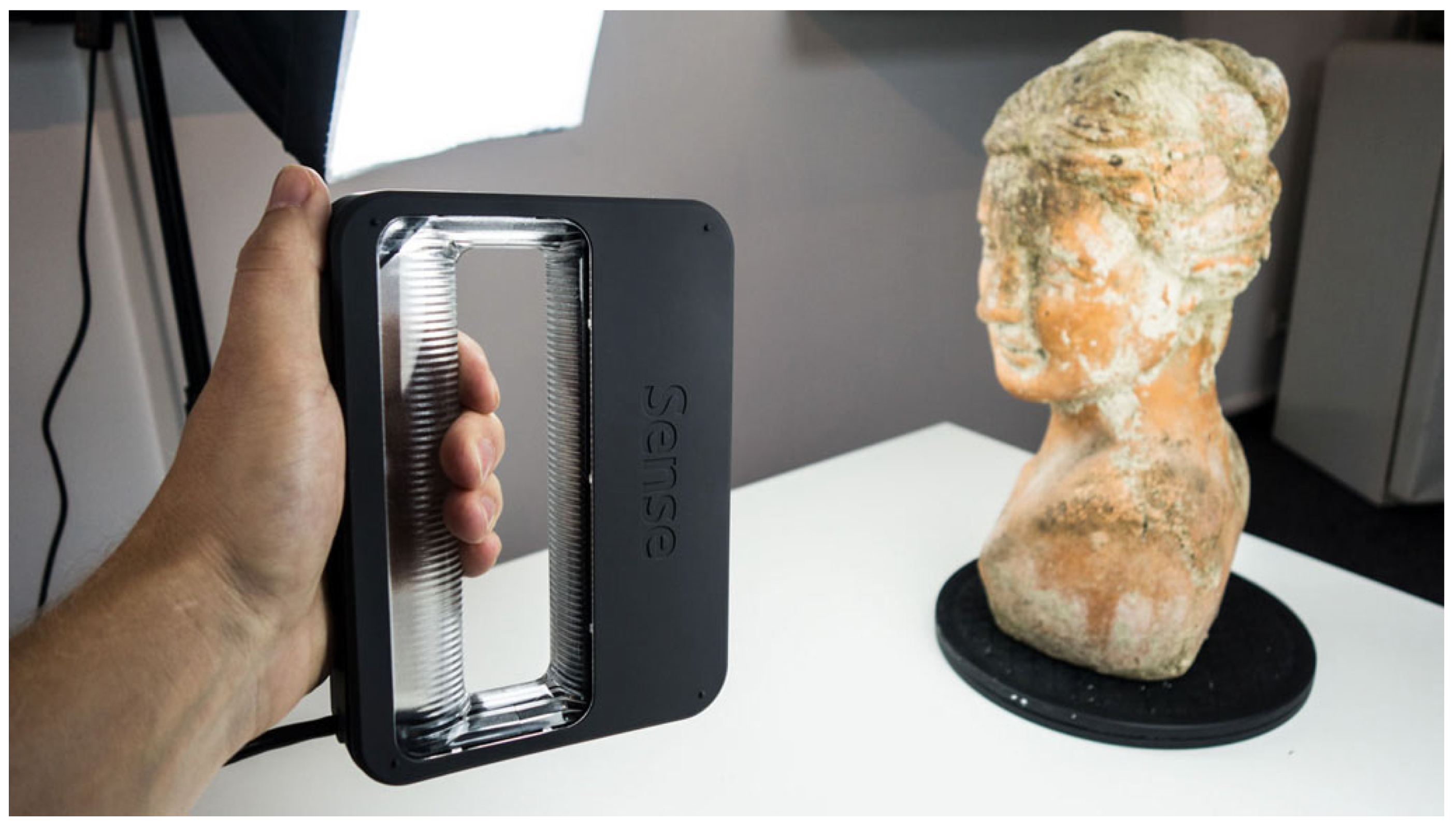
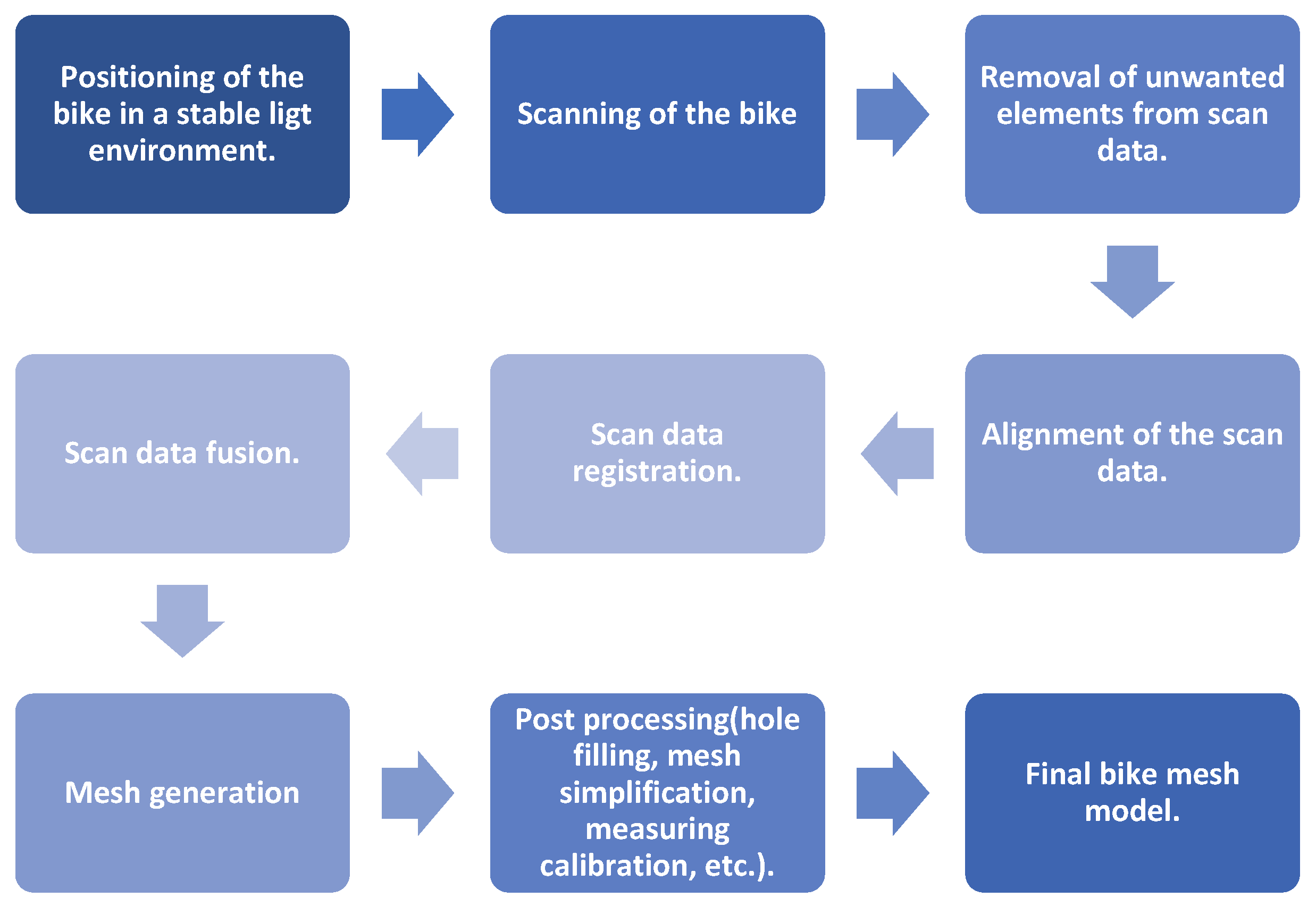
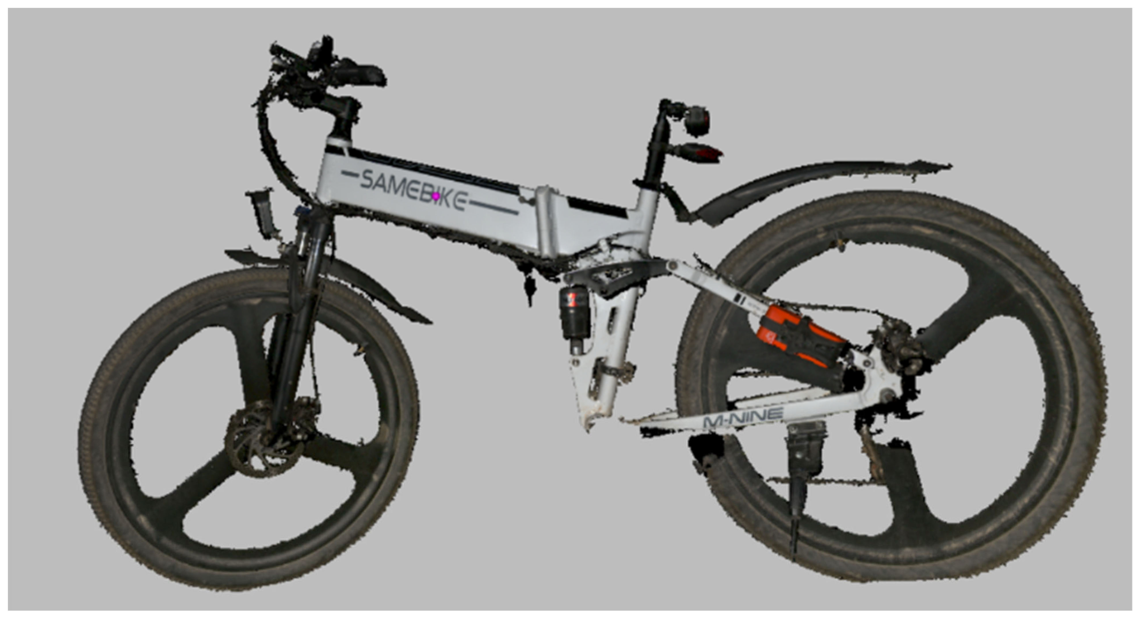
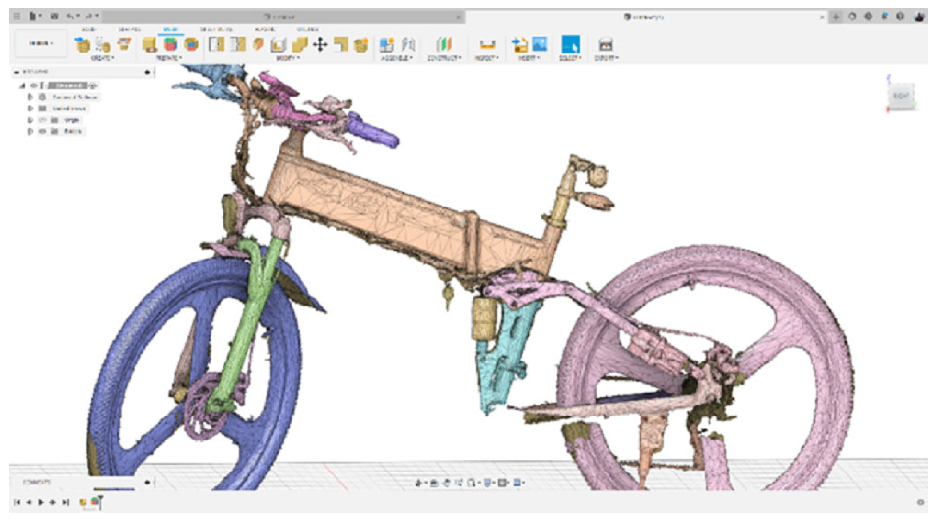
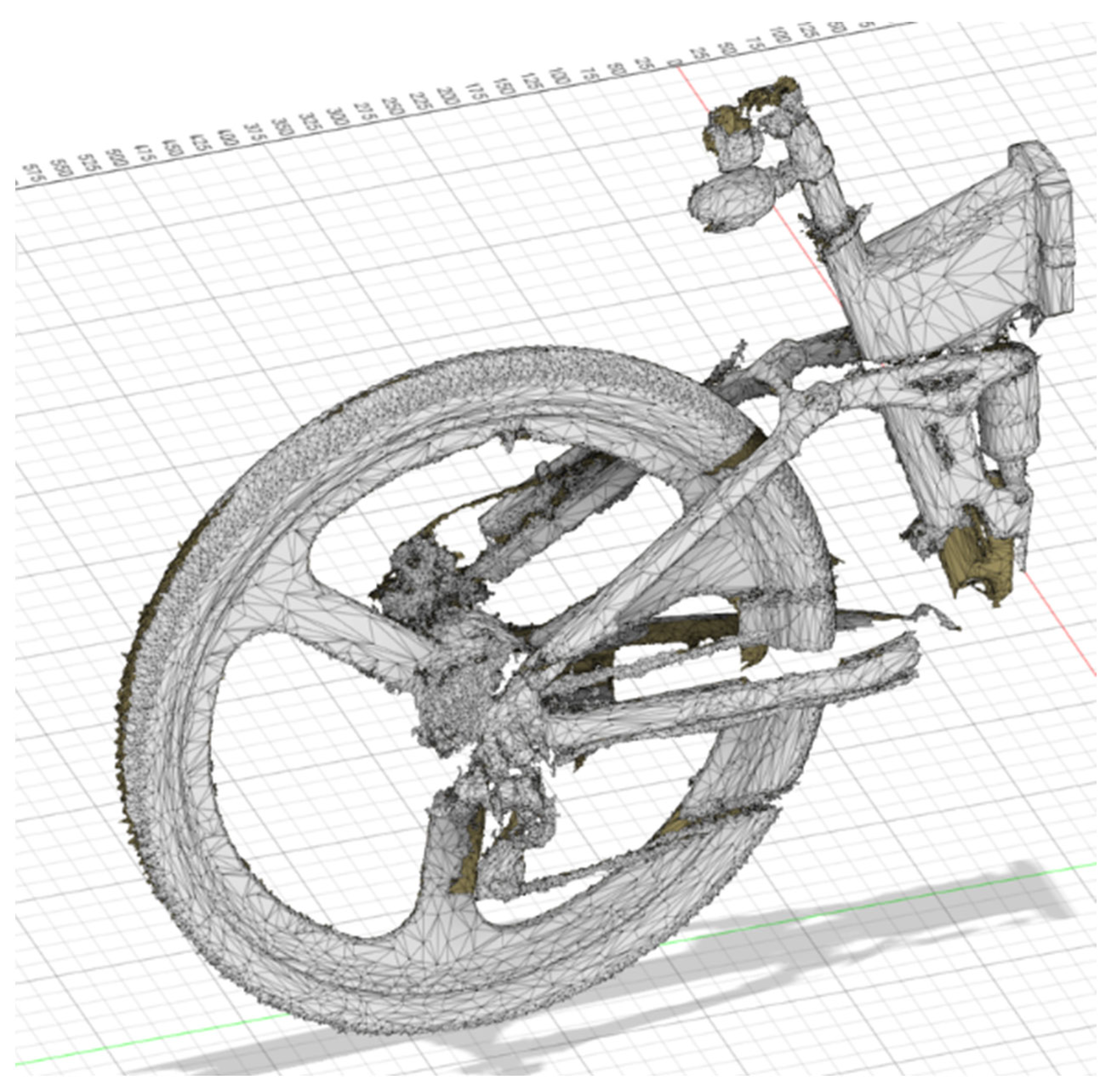
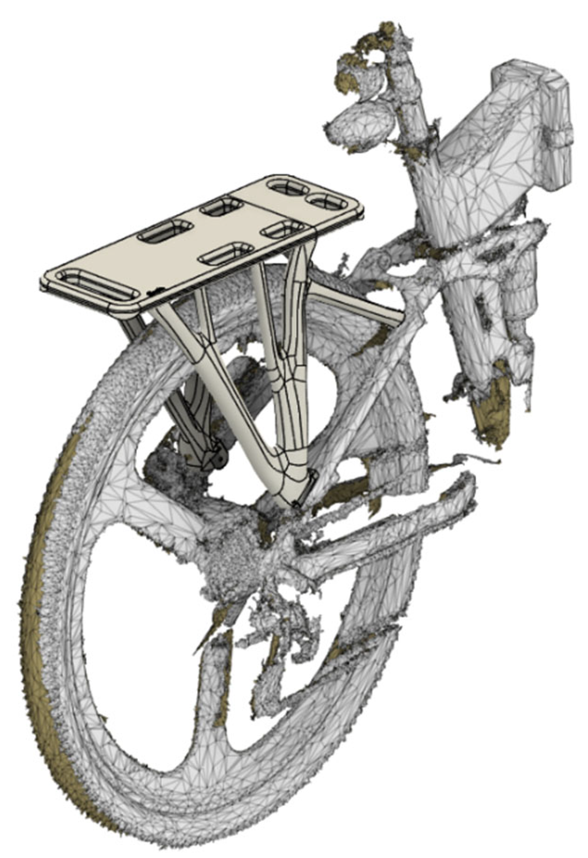
3.1. The 3D Scanning Process

The initial 3D scan results obtained from the 3D scanning procedure of the e-bike’s frame also included feature texture (color), and were processed in the dedicated 3D scanner’s Artec Design Studio® v.17 software. Figure 5 depicts the digitized version of the physical e-bike.
The generated digital file from the 3D scanning process was then imported into the work environment of the Fusion 360® software in order to perform section analysis. This process assists in selectively simplifying the generated mesh of the file. Figure 6 depicts a screenshot of the process.
The post-processing actions continued with further simplification of the mesh file with the reduction of triangles and a split of the 3D body, leaving only the area that the designer requires as a reference for visualization and measurements. Figure 7 depicts the result of the aforementioned actions.

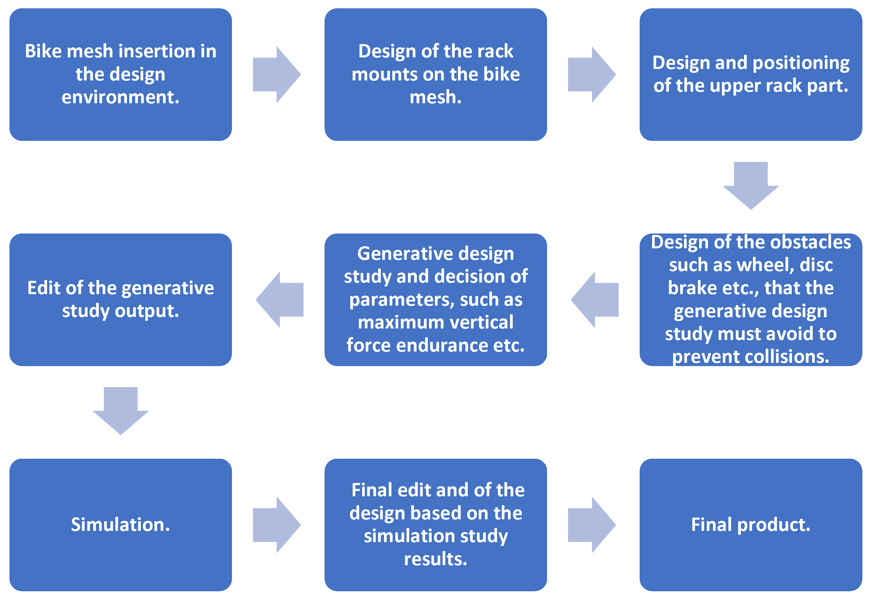
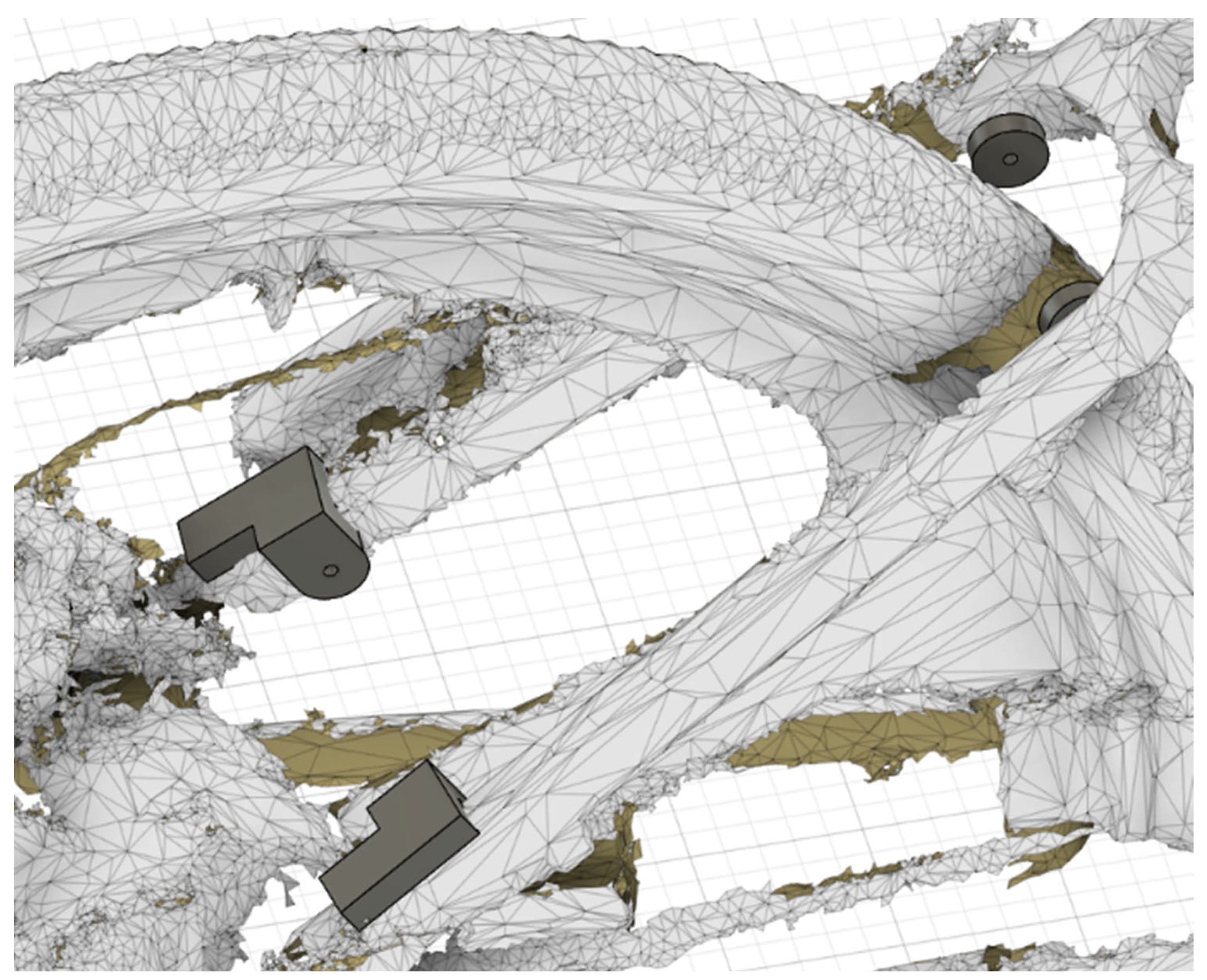
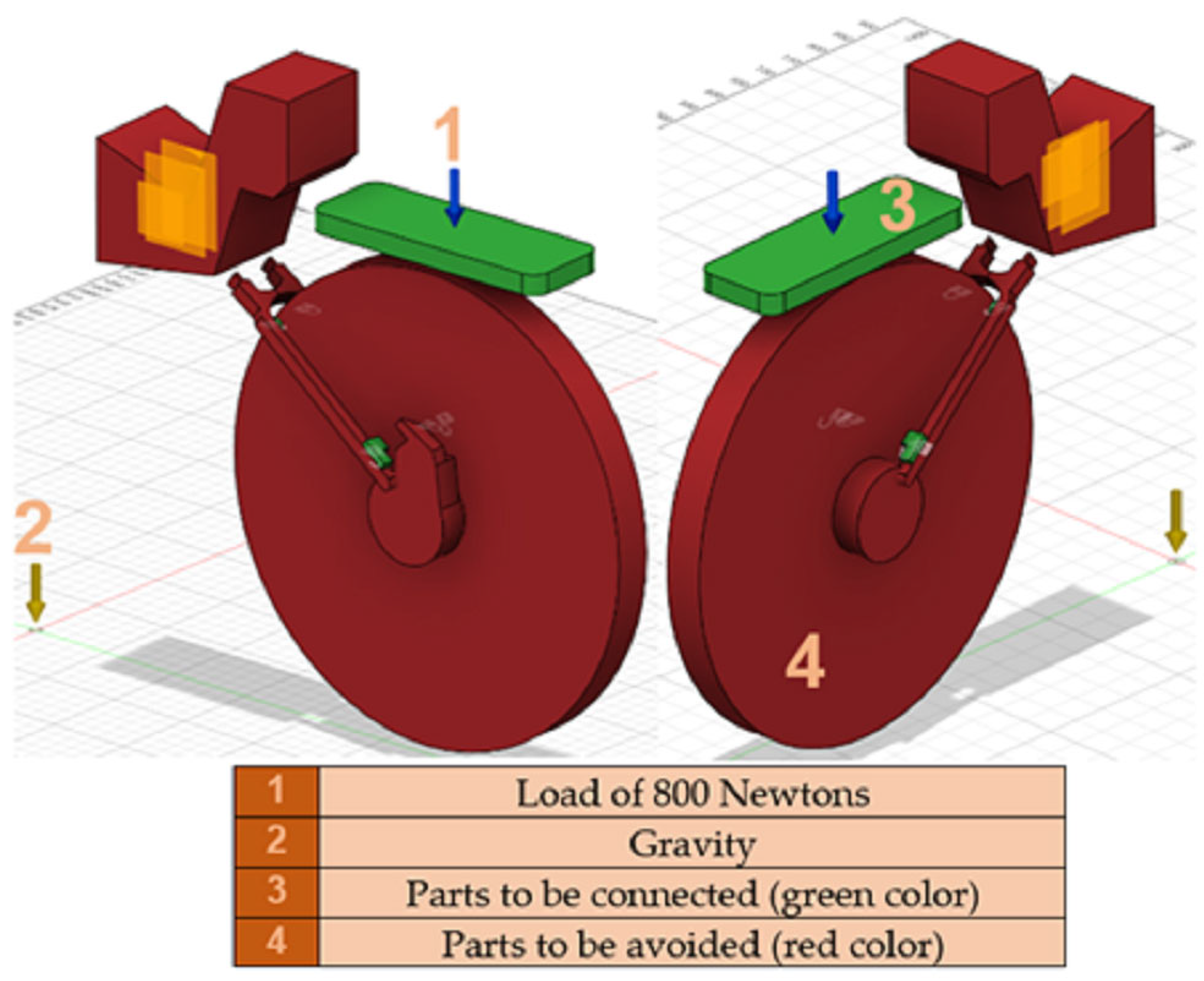
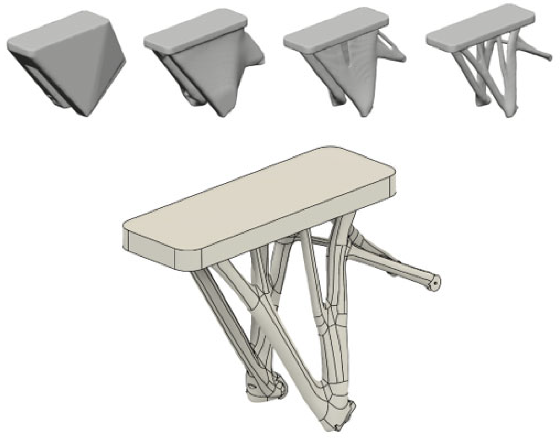
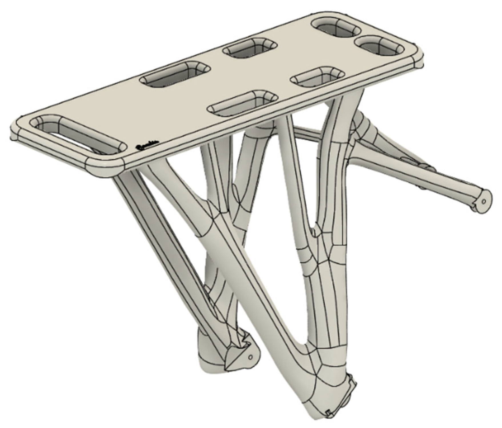
3.2. Generative Design Process

The generative design process was initiated at this stage. Generative design is an approach that utilizes computational algorithms to produce design solutions. There are several principles and rules of generative design that guide its implementation. Firstly, generative design aims to optimize performance based on the given constraints and objectives. This involves defining the goals of the design and specifying the parameters and constraints that need to be considered. Secondly, generative design is based on the principle of iteration, whereby multiple design options are generated and evaluated iteratively to arrive at an optimal solution. Another important principle is the use of generative algorithms to automate the design process and generate designs that are beyond human capabilities. Finally, generative design encourages the use of feedback loops to continuously improve the design, incorporating user feedback and adjusting the parameters to achieve better results. Figure 8 depicts the first iteration of one of the tail rack mounts, using the existing mesh geometry as a reference for measurements and object placement.
The generative design and simulation processes were carried out in Fusion 360® software. Highlighted with green color are the areas that the software will try to connect with the most optimal path using criteria such as mechanical strength, weight, manufacturing methods, and material of the generated part. Indicated with red color are the areas that the part will have to avoid, taking into close consideration clearances for the wheel and other obstacles such as the disk brakes. Last but not least, visible with yellow and blue arrows are the gravity force and the bike rack load force, respectively, as shown in Figure 9. The load that was applied in this simulation was 800 Newtons that implies approximately 800 N of load.
According to generative design modus operandi, the software generates different types of parts and improves them in each iteration. In the figure above, some of the process can be observed and the improvements are dramatic. As we can see, generative design uses a technique similar to topology optimization. For starters, a rough model of the part is generated and in iteration after iteration, mass is subtracted to achieve maximum mechanical properties with the least amount of material. The process took 29 iterations and the final part is shown in Figure 10 below.
The outcome of the generative design process is a T-spline solid body. This type of 3D model is easily modified in the Fusion 360® modeling workspace. Thus, further improvements and adjustments were implemented by the designer for the creation of the final product as depicted in Figure 11.
For fit and finishing purposes, the final product was digitally placed on the e-bike scanned model to ensure the compatibility as well as the accuracy of the rack mount. In this way, potential design mistakes can be swiftly detected. Another advantage of this technique is that it aids in the visualization of the real life product fit, as depicted in Figure 12.

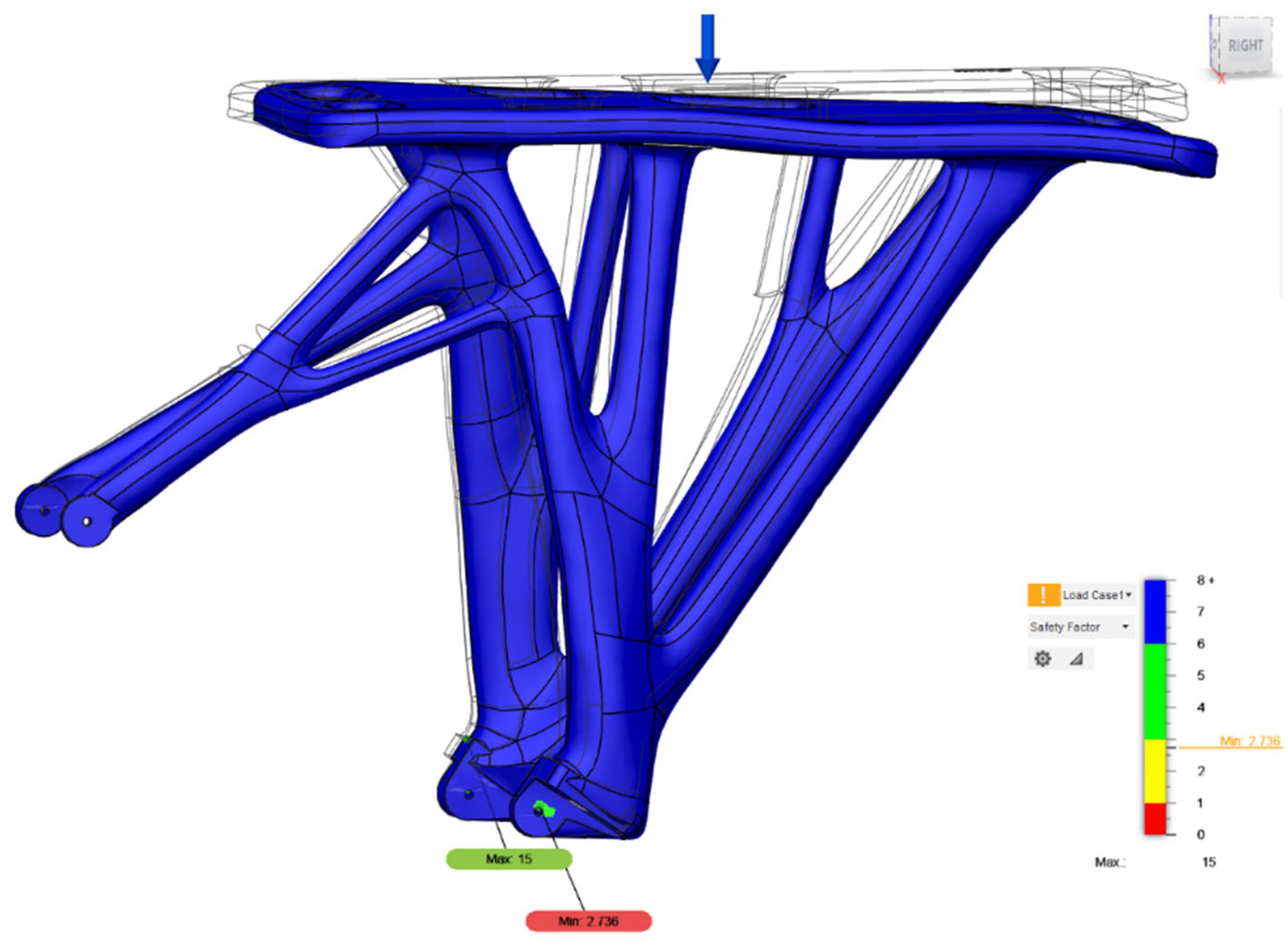
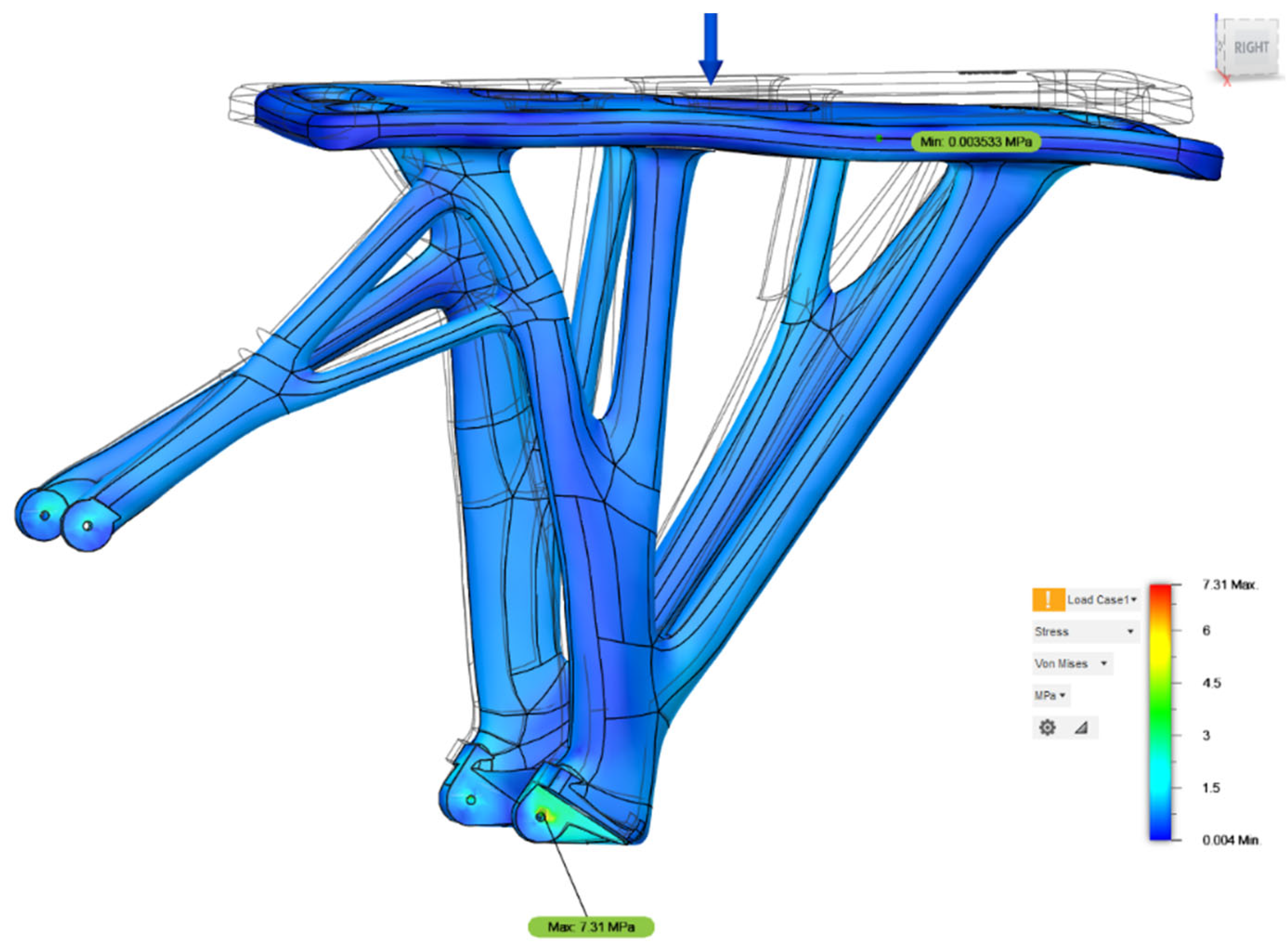
3.3. Simulation Process

In the simulation workspace of the Fusion 360® software, the part was tested using a static stress simulation, using the holes where the rack will be mounted with screws on the bike as fixed constrains. The force of stress in this simulation was 800 N ≈ 80 kg as seen in the figures below. A number of studies were generated in this environment consisting of a safety factor study, stress study, displacement study, reaction force study, strain study, contact pressure study, and contact force study. All of the studies corroborated the fact that the generative design procedure created an optimized part.
Figure 13 and Figure 14 are screenshots from the simulation environment of Fusion 360. Figure 13 visualizes the safety factor study, showing a minimum of 2.736, which is an exceptional outcome in consideration of the 800 N force that was applied on the rack. Figure 14 shows the stress study. We can observe that the most vulnerable part of the rack is the rack mounts, where a stress of 7.31 MPa was applied.

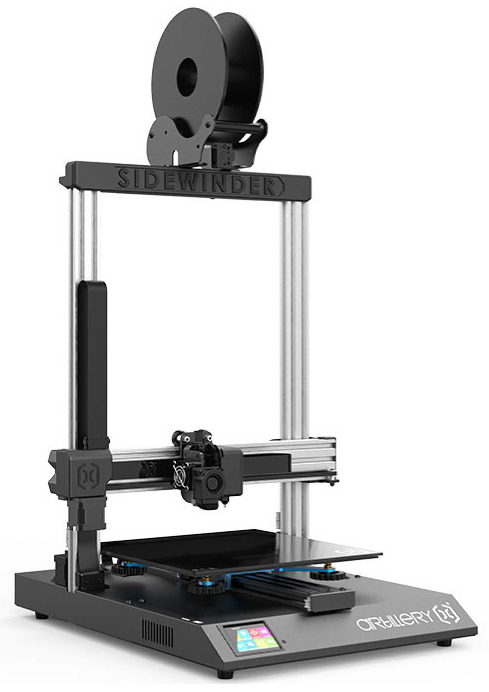
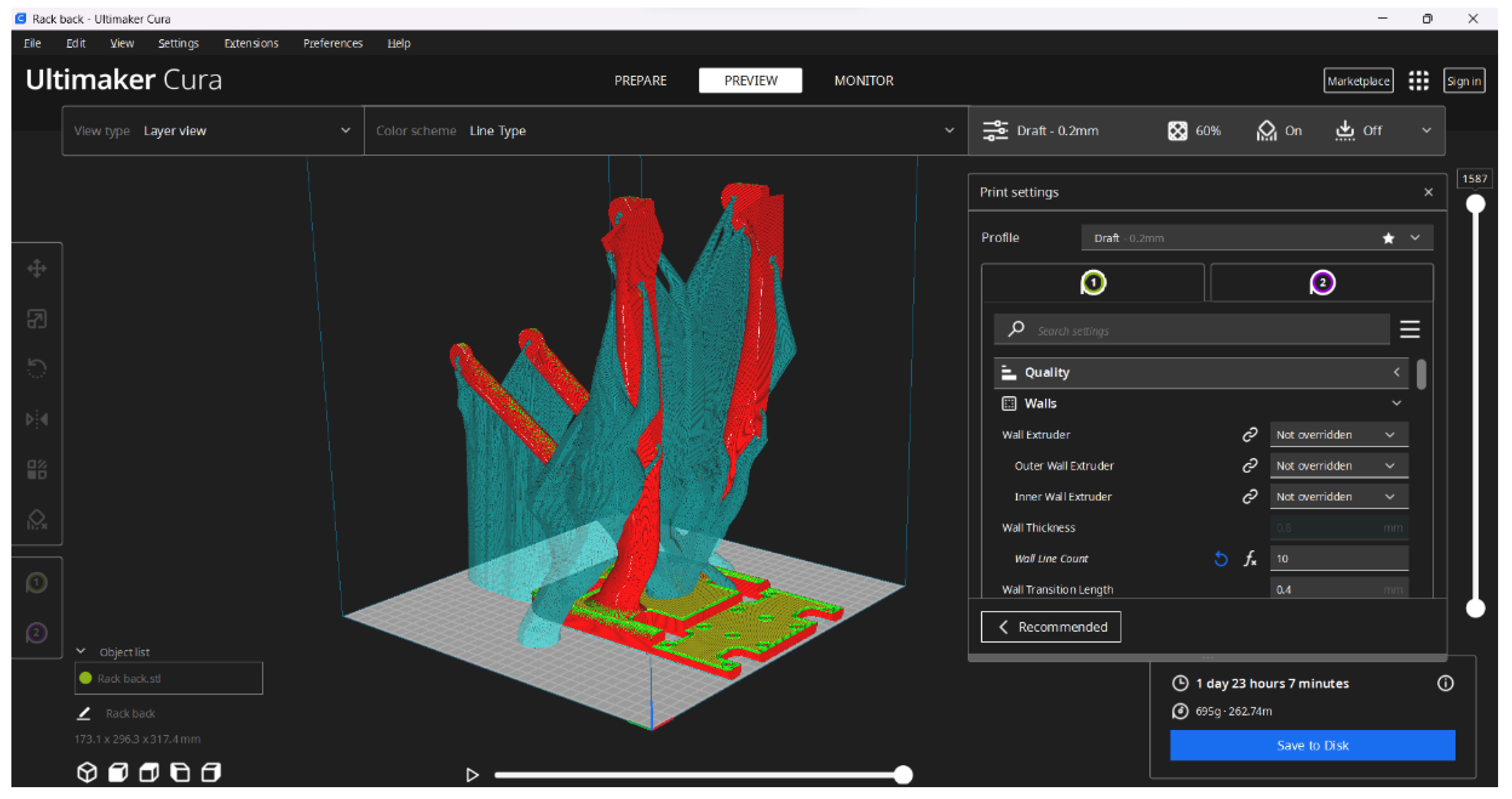
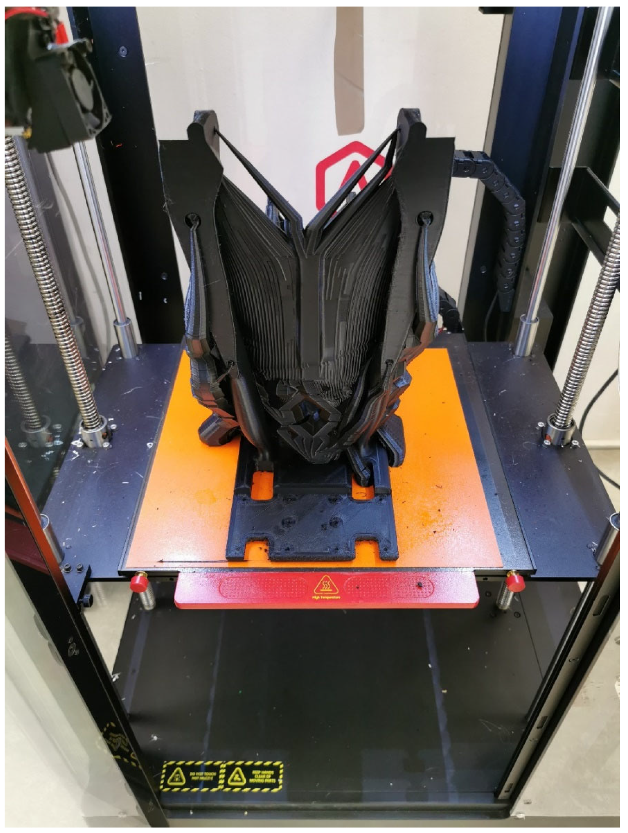
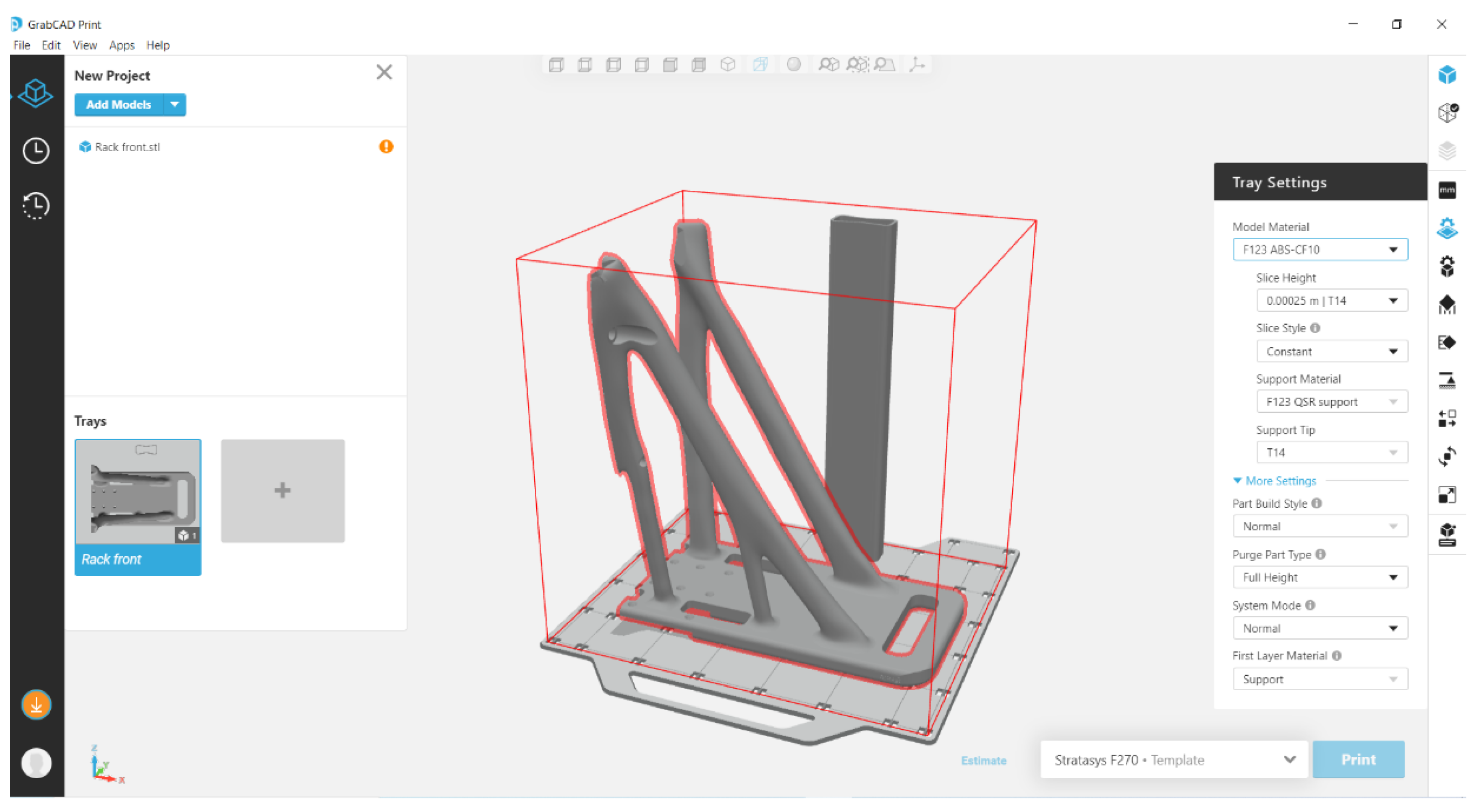
3.4. 3D Printing Process

Upon the finalization of the design and simulation processes, 3D printing of the designed part was conducted. As previously mentioned, a test/prototype part was fabricated in order to validate the designing process and to serve as a fit test. The final end-product was chosen to be the result of a separate 3D printing work with a different material, as stated earlier in the manuscript.
In this context, the test/prototype part was 3D printed using a Raise3d Pro2 Plus® FFF 3D printer. The material used was Innofil® ABS Fusion by BASF®. The processing parameters used in the 3D printing operation were the ones dictated by the manufacturer of the material (250 °C for the hot end temperature and 90 °C for the heated platform), while the speed was set at 60 mm/s and the retractable top lid was installed. To achieve optimal layer adhesion, the orientation of the print played a major role in obtaining good mechanical properties. With that in mind, the part’s geometry was designed to be printed vertically, in order to withstand the mechanical forces of the relevant application. Thus, all angles of the model were designed to be above 65 degrees in that orientation, enhancing printability, requiring less support material, and making it easier to print overall. For the slicing process, Ultimaker Cura slicing software was selected. Figure 15 shows a screenshot of the slicing process with the 3D model virtually placed in the 3D printer’s building volume, while Figure 16 shows the actual 3D printing process.
As far as the end-product is concerned, a Stratasys® F270 FDM 3D Printer with heated chamber was used. The material used was ABS CF10 by Stratasys®. The processing parameters used in the 3D printing operation were the ones dictated by the manufacturer of the material (in this case the dedicated slicing software does not allow the user to select). For the slicing process, the dedicated GrabCad Print® slicing software from Stratasys® was used. Figure 17 shows a screenshot of the slicing process with the 3D model virtually placed in the 3D printer’s building volume.

4. Discussion

Upon the completion of the fabrication process, both the prototype and the final peripheral component end-product were sequentially installed on the e-bike’s frame. In both cases, the fit proved to be flawless and the process can be characterized as successful. At this point, it is important to mention that the dimensional tolerance of the scan data was cross-referenced with the measurements of a caliper at critical points such as the width of the fork and the positions of the holes, among others. The use of the 3D scanner was crucial because it helped speed up the measuring process of the 3D dimensional part. The same work could be accomplished with the use of a caliper and laser inclinometer, but there would be more room for human error while changing the position of the measuring tool. Moreover, the rear end of the bike would have to be disassembled for the measuring tools to fit correctly. Figure 18 shows the installed component that now serves as end-product on the e-bike.
As stated earlier in the manuscript, the authors decided to use ABS-CF10 material which, despite being a thermoplastic ABS-based material, was introduced as a material that can replace metal for lighter and more ergonomic component fabrication. In principle, this claim sounded unrealistic a few years ago. However, this material category which uses a thermoplastic matrix reinforced by the presence of fibers or powder (carbon fibers in this case) is very promising in the sense of exhibiting similar properties to metal alloys. Another advantage of this material category is its ease of processability. Being able to utilize such materials in regular FDM 3D printers offers a great potential to end-users that do not have the infrastructure to fabricate metal parts.
With the principal of design for manufacturing in mind, the authors made the choice to digitally split the end product into two parts. This action offered the ability to print this large volume 3D product on smaller 3D printers as they are more widely available to the public. Another advantage of the two smaller parts is the option to print them in two separate 3D printers and practically cut the production time in half. To ensure that the new split product will maintain optimal mechanical properties, some additional design implementations had to be included. Firstly, pre-tapped holes were implemented in the existing design. These holes will guide stainless steel bolts that will hold the two parts firmly together. In addition, epoxy-based adhesive was applied on the surface where the two parts touched. This technique added an approximately 30 Mpa adhesive strength between the two parts according to literature reports [72]. To cross-reference the mechanical properties of the new split design compared to the solid part, an additional simulation was created. The results of the simulation were very promising; the reduction of the mechanical behavior of the split design were insignificant and the finished product was almost as strong as the solid one. The reason behind the results of the simulation is the placement of the “cut”. Instead of just adding a plane cut to the model, the choice was made to apply a T pattern cut, drastically increasing the adhesion surface. That implementation led to better adhesion and greater mechanical properties.
Based on the presented workflow, the combination of 3D scanning, 3D printing, and CAD generative design methods proved to be very valuable in terms of allowing the swift and precise fabrication of custom end-use products. In this way, the research and development process time are minimized while the fabrication process is faster. In addition, the introduction of new composite materials that feature a thermoplastic matrix allow their use in regular FDM and FFF 3D printers that are widely available and are continuously progressing and evolving over time.
An interesting aspect could concern how small- and medium-sized enterprises (SMEs) can adopt the proposed methodology, by incorporating 3D printing, generative design, and 3D scanning. Firstly, SMEs should first identify their needs, such as prototyping or product design, that can be addressed by 3D printing, generative design, or 3D scanning. Then, after identifying their needs, SMEs should research different 3D printing, generative design, and 3D scanning technologies, their capabilities, and their costs. Based on their research, SMEs should evaluate their options and choose the most suitable technology for their needs and budget. Consequently, SMEs should invest in relevant hardware and software. This includes 3D printers, 3D scanners, generative design software, and CAD software. Employees should be trained on how to use the hardware and software by hiring experts or outsourcing training services. Another step can be the implementation of pilot projects to test the technology, identify challenges, and refine their processes. This can help to minimize risks and avoid costly mistakes. Collaborating with experts should be considered, such as 3D printing service providers or design consultants, to optimize their processes and leverage their expertise [73,74]. Lastly, SMEs should continuously improve their processes by monitoring their results, identifying areas for improvement, and implementing changes. By following these steps, SMEs can adopt the proposed methodology and take advantage of its benefits, such as faster prototyping, reduced costs, and improved product design.

5. Conclusions

The current work depicts the potential of combining 3D scanning, 3D printing, and CAD generative design methods towards fabricating a customized, end-product component. In this case, an e-bike was 3D scanned in order to digitize its geometrical characteristics. This was vital in designing a peripheral component (a tail rack in this case) that would be seamlessly attached onto the bike’s frame. Instead of just designing a tail rack from scratch, a CAD generative design method was selected in order to generate a design that would favor light weight and optimum mechanical behaviors at the same time. In order to fabricate the final design, a FDM 3D printing method was used by employing ABS-CF10 materials which, despite being a thermoplastic ABS-based material, was introduced as a material that can replace metal for lighter and more ergonomic component fabrication. Therefore, the component was fabricated in this manner and was installed successfully on the e-bike’s frame. The proposed procedure is not limited to this component’s fabrication and has the potential to be employed in the fabrication of other peripheral components and tooling as future work.

Author Contributions

Conceptualization, A.K.; methodology, A.K. and E.S.; software, A.K. and E.S.; validation, A.K. and E.S.; formal analysis, A.K. and E.S.; investigation, A.K.; resources, A.K. and E.S.; data curation, E.S.; writing—original draft, A.K. and E.S.; writing—review and editing, A.K. and E.S.; visualization, A.K.; supervision, T.G. and F.I.T.P.; project administration, T.G. and F.I.T.P. All authors have read and agreed to the published version of the manuscript.

Funding

This research received no external funding.

Data Availability Statement

Not applicable.

Acknowledgments

The authors would like to thank “BlueLab” makerspace in Piraeus, Greece, for providing the Stratasys F270 3D printer and the raw materials that were used in the fabrication process of the proposed peripheral component.

Conflicts of Interest

The authors declare no conflict of interest.

References

  1. Jeong, E.; Kim, Y.; Hong, S.; Yoon, K.; Lee, S. Innovative Injection Molding Process for the Fabrication of Woven Fabric Reinforced Thermoplastic Composites. Polymers 2022, 14, 1577. [Google Scholar] [CrossRef] [PubMed]
  2. Petráček, P.; Fojtů, P.; Kozlok, T.; Sulitka, M. Effect of CNC Interpolator Parameter Settings on Toolpath Precision and Quality in Corner Neighborhoods. Appl. Sci. 2022, 12, 9496. [Google Scholar] [CrossRef]
  3. Elverum, C.W.; Welo, T. On the use of directional and incremental prototyping in the development of high novelty products: Two case studies in the automotive industry. J. Eng. Technol. Manag. 2015, 38, 71–88. [Google Scholar] [CrossRef]
  4. Rayna, T.; Striukova, L.; Darlington, J. Co-creation and user innovation: The role of online 3D printing platforms. J. Eng. Technol. Manag. 2015, 37, 90–102. [Google Scholar] [CrossRef]
  5. Kantaros, A.; Diegel, O.; Piromalis, D.; Tsaramirsis, G.; Khadidos, A.O.; Khadidos, A.O.; Khan, F.Q.; Jan, S. 3D printing: Making an innovative technology widely accessible through makerspaces and outsourced services. Mater. Today Proc. 2022, 49, 2712–2723. [Google Scholar] [CrossRef]
  6. Mersand, S. The State of Makerspace Research: A Review of the Literature. TechTrends 2021, 65, 174–186. [Google Scholar] [CrossRef]
  7. Lettl, C. User involvement competence for radical innovation. J. Eng. Technol. Manag. 2007, 24, 53–75. [Google Scholar] [CrossRef]
  8. Kantaros, A.; Piromalis, D. Fabricating Lattice Structures via 3D Printing: The Case of Porous Bio-Engineered Scaffolds. Appl. Mech. 2021, 2, 289–302. [Google Scholar] [CrossRef]
  9. Kantaros, A.; Laskaris, N.; Piromalis, D.; Ganetsos, T. Manufacturing Zero-Waste COVID-19 Personal Protection Equipment: A Case Study of Utilizing 3D Printing While Employing Waste Material Recycling. Circ. Econ. Sustain. 2021, 1, 851–869. [Google Scholar] [CrossRef]
  10. Kantaros, A.; Piromalis, D. Employing a Low-Cost Desktop 3D Printer: Challenges, and How to Overcome Them by Tuning Key Process Parameters. Int. J. Mech. Appl. 2021, 10, 11–19. [Google Scholar] [CrossRef]
  11. Kantaros, A.; Chatzidai, N.; Karalekas, D. 3D printing-assisted design of scaffold structures. Int. J. Adv. Manuf. Technol. 2016, 82, 559–571. [Google Scholar] [CrossRef]
  12. Kantaros, A.; Karalekas, D. FBG based in situ characterization of residual strains in FDM process. In Residual Stress, Thermomechanics & Infrared Imaging, Hybrid Techniques and Inverse Problems; Springer: Cham, Switzerland, 2014; Volume 8, pp. 333–337. [Google Scholar] [CrossRef]
  13. Kantaros, A.; Giannatsis, J.; Karalekas, D. A novel strategy for the incorporation of optical sensors in Fused Deposition Modeling parts. In Proceedings of the International Conference on Advanced Manufacturing Engineering and Technologies, Stockolm, Sweden, 27–30 October 2013; Universitets Service US AB, KTH Royal Institite of Technology: Stockholm, Sweden, 2013. ISBN 978-91-7501-893-5. [Google Scholar]
  14. Kantaros, A.; Karalekas, D. Fiber Bragg grating based investigation of residual strains in ABS parts fabricated by fused deposition modeling process. Mater. Des. 2013, 50, 44–50. [Google Scholar] [CrossRef]
  15. Haleem, A.; Javaid, M.; Singh, R.P.; Rab, S.; Suman, R.; Kumar, L.; Khan, I.H. Exploring the potential of 3D scanning in Industry 4.0: An overview. Int. J. Cogn. Comput. Eng. 2022, 3, 161–171. [Google Scholar] [CrossRef]
  16. Bugeja, A.; Bonanno, M.; Garg, L. 3D scanning in the art & design industry. Mater. Today Proc. 2022, 63, 718–725. [Google Scholar] [CrossRef]
  17. Derusova, D.A.; Vavilov, V.P.; Druzhinin, N.V.; Shpil’noi, V.Y.; Pestryakov, A.N. Detecting Defects in Composite Polymers by Using 3D Scanning Laser Doppler Vibrometry. Materials 2022, 15, 7176. [Google Scholar] [CrossRef]
  18. Bendsøe, M.P.; Sigmund, O. Topology Optimization: Theory, Methods and Applications; Springer: Berlin/Heidelberg, Germany, 2003; ISBN 3-540-42992-1. [Google Scholar]
  19. Liu, Y.; Li, Z.; Wei, P.; Chen, S. Generating support structures for additive manufacturing with continuum topology optimization methods. Rapid Prototyp. J. 2019, 25, 232–246. [Google Scholar] [CrossRef]
  20. Jiang, L.; Ye, H.; Zhou, C.; Chen, S. Parametric Topology Optimization Toward Rational Design and Efficient Prefabrication for Additive Manufacturing. J. Manuf. Sci. Eng. Trans. ASME 2019, 141, 041007. [Google Scholar] [CrossRef]
  21. Jiang, D.; Hoglund, R.; Smith, D.E. Continuous Fiber Angle Topology Optimization for Polymer Composite Deposition Additive Manufacturing Applications. Fibers 2019, 7, 14. [Google Scholar] [CrossRef]
  22. Zhu, D.; Zhan, W.; Wu, F.; Simeone, A. Topology Optimization of Spatially Compliant Mechanisms with an Isomorphic Matrix of a 3-UPC Type Parallel Prototype Manipulator. Micromachines 2018, 9, 184. [Google Scholar] [CrossRef]
  23. Garaigordobil, A.; Ansola, R.; Veguería, E.; Fernandez, I. Overhang constraint for topology optimization of self-supported compliant mechanisms considering additive manufacturing. Comput. Aided Des. 2019, 110, 33–48. [Google Scholar] [CrossRef]
  24. Zhu, J.; Zhou, H.; Wang, C.; Zhou, L.; Yuan, S.; Zhang, W. A review of topology optimization for additive manufacturing: Status and challenges. Chin. J. Aeronaut. 2021, 34, 91–110. [Google Scholar] [CrossRef]
  25. Bendsøe, M.P.; Sigmund, O. Topology optimization by distribution of isotropic material. In Topology Optimization; Springer: Berlin/Heidelberg, Germany, 2004. [Google Scholar]
  26. Junk, S.; Klerch, B.; Nasdala, L.; Hochberg, U. Topology optimization for additive manufacturing using a component of a humanoid robot. Procedia CIRP 2018, 70, 102–107. [Google Scholar] [CrossRef]
  27. Orme, M.; Madera, I.; Gschweitl, M.; Ferrari, M. Topology Optimization for Additive Manufacturing as an Enabler for Light Weight Flight Hardware. Designs 2018, 2, 51. [Google Scholar] [CrossRef]
  28. Sadri, M.; Kavandi, M.; Jozepiri, A.; Teimouri, S.; Abbasi, F. Bionic Architecture, Forms and Constructions. Res. J. Recent Sci. 2014, 3, 93–98. [Google Scholar]
  29. Ding, Y.; Zhou, Z.; Wang, Z.; Liu, H.; Wang, K. Bionic Stiffener Layout Optimization with a Flexible Plate in Solar-Powered UAV Surface Structure Design. Appl. Sci. 2019, 9, 5196. [Google Scholar] [CrossRef]
  30. Christiansen, A.N.; Bærentzen, J.A.; Nobel-Jørgensen, M.; Aage, N.; Sigmund, O. Combined shape and topology optimization of 3D structures. Comput. Graph. 2015, 46, 25–35. [Google Scholar] [CrossRef]
  31. Wang, L.; Du, W.; He, P.; Yang, M. Topology Optimization and 3D Printing of Three-Branch Joints in Treelike Structures. J. Struct. Eng. 2020, 146, 04019167. [Google Scholar] [CrossRef]
  32. Primo, T.; Calabrese, M.; Del Prete, A.; Anglani, A. Additive manufacturing integration with topology optimization methodology for innovative product design. Int. J. Adv. Manuf. Technol. 2017, 93, 467–479. [Google Scholar] [CrossRef]
  33. Significant Weight Reduction by Using Topology Optimization in Volkswagen Design Development. Available online: https://www.altair.com/resource/significant-weight-reduction-by-using-topology-optimization-in-volkswagen-design-development (accessed on 3 December 2022).
  34. BMW 3D Printing Superbike Components at the Track|3D-Prints. Available online: https://3d-prints.com/2020/11/04/bmw-3d-printing-superbike-components-at-the-track/ (accessed on 3 December 2022).
  35. Airbus APWorks Launches the ‘Light Rider’: The World’s First 3D-Printed Motorcycle. Available online: https://www.airbus.com/newsroom/press-releases/en/2016/05/APWorks-Launch-Light-Rider.html (accessed on 3 December 2022).
  36. Topology Optimization of Aircraft Wing Box Ribs. Available online: https://www.altair.com/resource/topology-optimization-of-aircraft-wing-box-ribs (accessed on 8 February 2022).
  37. Felipe-Falgas, P.; Madrid-Lopez, C.; Marquet, O. Assessing Environmental Performance of Micromobility Using LCA and Self-Reported Modal Change: The Case of Shared E-Bikes, E-Scooters, and E-Mopeds in Barcelona. Sustainability 2022, 14, 4139. [Google Scholar] [CrossRef]
  38. Pazzini, M.; Cameli, L.; Lantieri, C.; Vignali, V.; Dondi, G.; Jonsson, T. New Micromobility Means of Transport: An Analysis of E-Scooter Users’ Behaviour in Trondheim. Int. J. Environ. Res. Public Health 2022, 19, 7374. [Google Scholar] [CrossRef]
  39. Park, J.; Honda, Y.; Fujii, S.; Kim, S.E. Air Pollution and Public Bike-Sharing System Ridership in the Context of Sustainable Development Goals. Sustainability 2022, 14, 3861. [Google Scholar] [CrossRef]
  40. Harrou, F.; Dairi, A.; Zeroual, A.; Sun, Y. Forecasting of Bicycle and Pedestrian Traffic Using Flexible and Efficient Hybrid Deep Learning Approach. Appl. Sci. 2022, 12, 4482. [Google Scholar] [CrossRef]
  41. Wysling, L.; Purves, R.S. Where to improve cycling infrastructure? Assessing bicycle suitability and bikeability with open data in the city of Paris. Transp. Res. Interdiscip. Perspect. 2022, 15, 100648. [Google Scholar] [CrossRef]
  42. Santos, B.; Passos, S.; Gonçalves, J.; Matias, I. Spatial Multi-Criteria Analysis for Road Segment Cycling Suitability Assessment. Sustainability 2022, 14, 9928. [Google Scholar] [CrossRef]
  43. Reggiani, G.; van Oijen, T.; Hamedmoghadam, H.; Daamen, W.; Vu, H.L.; Hoogendoorn, S. Understanding bikeability: A methodology to assess urban networks. Transportation 2022, 49, 897–925. [Google Scholar] [CrossRef]
  44. Kellstedt, D.K.; Spengler, J.O.; Foster, M.; Lee, C.; Maddock, J.E. A Scoping Review of Bikeability Assessment Methods. J. Community Health 2021, 46, 211–224. [Google Scholar] [CrossRef]
  45. Krenn, P.J.; Oja, P.; Titze, S. Development of a Bikeability Index to Assess the Bicycle-Friendliness of Urban Environments. Open J. Civ. Eng. 2015, 5, 451–459. [Google Scholar] [CrossRef]
  46. Schmid-Querg, J.; Keler, A.; Grigoropoulos, G. The Munich Bikeability Index: A Practical Approach for Measuring Urban Bikeability. Sustainability 2021, 13, 428. [Google Scholar] [CrossRef]
  47. Karanikola, P.; Panagopoulos, T.; Tampakis, S.; Tsantopoulos, G. Cycling as a Smart and Green Mode of Transport in Small Touristic Cities. Sustainability 2018, 10, 268. [Google Scholar] [CrossRef]
  48. Grisé, E.; El-Geneidy, A. If we build it, who will benefit? A multi-criteria approach for the prioritization of new bicycle lanes in Quebec City, Canada. J. Transp. Land Use 2018, 11, 217–235. [Google Scholar] [CrossRef]
  49. Rietveld, P. Biking and Walking: The Position of Non-Motorized Transport Modes in Transport Systems. In Handbook of Transport Systems and Traffic Control; Button, K.J., Hensher, D.A., Eds.; Emerald Group Publishing Limited: Bingley, UK, 2001. [Google Scholar]
  50. Hardinghaus, M.; Papantoniou, P. Evaluating Cyclists’ Route Preferences with Respect to Infrastructure. Sustainability 2020, 12, 3375. [Google Scholar] [CrossRef]
  51. Prato, C.G.; Halldórsdóttir, K.; Nielsen, O.A. Evaluation of land-use and transport network effects on cyclists’ route choices in the Copenhagen Region in value-of-distance space. Int. J. Sustain. Transp. 2018, 12, 770–781. [Google Scholar] [CrossRef]
  52. McKinsey & Company. Available online: https://www.mckinsey.com/industries/automotive-and-assembly/our-insights/why-micromobility-is-here-to-stay (accessed on 15 November 2022).
  53. Carroll, P. Perceptions of Electric Scooters Prior to Legalisation: A Case Study of Dublin, Ireland, the ‘Final Frontier’ of Adopted E-Scooter Use in Europe. Sustainability 2022, 14, 11376. [Google Scholar] [CrossRef]
  54. Hamzani, Y.; Demtriou, H.; Zelnik, A.; Cohen, N.; Drescher, M.J.; Chaushu, G.; Yahya, B.H. Age as a Predictive Factor in Severity of Injuries in Riders of Electric Bikes and Powered Scooters: A Retrospective Cross-Sectional Study. Healthcare 2022, 10, 1689. [Google Scholar] [CrossRef] [PubMed]
  55. Meir, A. Can Complete-Novice E-Bike Riders Be Trained to Detect Unmaterialized Traffic Hazards in the Urban Environment? An Exploratory Study. Sustainability 2022, 14, 10869. [Google Scholar] [CrossRef]
  56. Noh, E.; Hong, S. Finite Element Analysis and Support Vector Regression-Based Optimal Design to Minimize Deformation of Indoor Bicycle Handle Frame Equipped with Monitor. Appl. Sci. 2022, 12, 2999. [Google Scholar] [CrossRef]
  57. Khutal, K.; Kathiresan, G.; Ashok, K.; Simhachalam, B.; Jebaseelan, D.D. Design Validation Methodology for Bicycle Frames Using Finite Element Analysis. Mater. Today Proc. 2020, 22, 1861–1869. [Google Scholar] [CrossRef]
  58. Devaiah, B.; Purohit, R.; Rana, R.; Parashar, V. Stress Analysis of A Bicycle Frame. Int. J. Eng. Sci. Technol. 2018, 5, 18920–18926. [Google Scholar] [CrossRef]
  59. Covill, D.; Begg, S.; Elton, E.; Milne, M.; Morris, R.; Katz, T. Parametric Finite Element Analysis of Bicycle Frame Geometries. Procedia Eng. 2014, 72, 441–446. [Google Scholar] [CrossRef]
  60. Khade, H.A.; Narwade, P.A. Structural Analysis of Two Wheeler Handlebar. Int. J. Adv. Sci. Technol. 2014, 68, 65–76. [Google Scholar] [CrossRef]
  61. Zdravkovich, M. Aerodynamics of bicycle wheel and frame. J. Wind. Eng. Ind. Aerodyn. 1992, 40, 55–70. [Google Scholar] [CrossRef]
  62. Tomaszewski, T. Fatigue life analysis of steel bicycle frame according to ISO 4210. Eng. Fail. Anal. 2021, 122, 105195. [Google Scholar] [CrossRef]
  63. Hsiao, S.-W.; Chen, R.-Q.; Leng, W.-L. Applying riding-posture optimization on bicycle frame design. Appl. Ergon. 2015, 51, 69–79. [Google Scholar] [CrossRef]
  64. Liu, T.J.-C.; Wu, H.-C. Fiber direction and stacking sequence design for bicycle frame made of carbon/epoxy composite laminate. Mater. Des. 2010, 31, 1971–1980. [Google Scholar] [CrossRef]
  65. Lépine, J.; Champoux, Y.; Drouet, J.-M. The relative contribution of road bicycle components on vibration induced to the cyclist. Sport. Eng. 2015, 18, 79–91. [Google Scholar] [CrossRef]
  66. Covill, D.; Allard, P.; Drouet, J.-M.; Emerson, N. An Assessment of Bicycle Frame Behaviour under Various Load Conditions Using Numerical Simulations. Procedia Eng. 2016, 147, 665–670. [Google Scholar] [CrossRef]
  67. Malizia, F.; Blocken, B. Bicycle aerodynamics: History, state-of-the-art and future perspectives. J. Wind. Eng. Ind. Aerodyn. 2020, 200, 104134. [Google Scholar] [CrossRef]
  68. Mesicek, J.; Jancar, L.; Ma, Q.-P.; Hajnys, J.; Tanski, T.; Krpec, P.; Pagac, M. Comprehensive View of Topological Optimization Scooter Frame Design and Manufacturing. Symmetry 2021, 13, 1201. [Google Scholar] [CrossRef]
  69. Callens, A.; Bignonnet, A. Fatigue design of welded bicycle frames using a multiaxial criterion. Procedia Eng. 2012, 34, 640–645. [Google Scholar] [CrossRef]
  70. Behnam, H.; Kuang, J.S.; Samali, B. Parametric Finite Element Analysis of RC Wide Beam-Column Connections. Comput. Struct. 2018, 205, 28–44. [Google Scholar] [CrossRef]
  71. Covill, D.; Blayden, A.; Coren, D.; Begg, S. Parametric Finite Element Analysis of Steel Bicycle Frames: The Influence of Tube Selection on Frame Stiffness. Procedia Eng. 2015, 112, 34–39. [Google Scholar] [CrossRef]
  72. Choosing the Right Adhesive to Bond ABS Plastic: What You Need to Know. Available online: https://forgeway.com/choose-glue-to-bond-abs-plastic/ (accessed on 7 February 2022).
  73. Petrescu, R.V.V.; Petrescu, F.I.T. The current stage in aerospace at the end of 2020. Indep. J. Manag. Prod. 2022, 13, 405–478. [Google Scholar] [CrossRef]
  74. Aversa, R.; Petrescu, R.V.V.; Petrescu, F.I.T.; Apicella, A. Smart-Factory: Optimization and Process Control of Composite Centrifuged Pipes. Am. J. Appl. Sci. 2016, 13, 1330–1341. [Google Scholar] [CrossRef]
Figure 1. Desktop FFF 3D printer apparatus.
Processes 11 01385 g001
Figure 2. Handheld 3D scanner apparatus.
Processes 11 01385 g002
Figure 3. Proposed 3D scanning process flowchart.
Processes 11 01385 g003
Figure 4. Proposed 3D design process flowchart.
Processes 11 01385 g004
Figure 5. 3D scan results obtained from the 3D scanning procedure of the e-bike’s frame.
Processes 11 01385 g005
Figure 6. Screenshot of the post-processing actions in Fusion 360 software.
Processes 11 01385 g006
Figure 7. Post-processing actions including further mesh simplification and a virtual split of the 3D body.
Processes 11 01385 g007
Figure 8. Generative design process initiation with tail rack mounts outcome.
Processes 11 01385 g008
Figure 9. Simulation process.
Processes 11 01385 g009
Figure 10. Generative design process from initial to final design.
Processes 11 01385 g010
Figure 11. Final design as the result of designer intervention.
Processes 11 01385 g011
Figure 12. Digital placement of the designed peripheral component on the 3D scanned bike’s frame.
Processes 11 01385 g012
Figure 13. Safety factor simulation study.
Processes 11 01385 g013
Figure 14. Stress factor simulation study.
Processes 11 01385 g014
Figure 15. Screenshot of the slicing process with the 3D model virtually placed in the 3D printer’s building volume.
Processes 11 01385 g015
Figure 16. Actual 3D printing process.
Processes 11 01385 g016
Figure 17. Screenshot of the slicing process with the 3D model virtually placed in the 3D printer’s building volume.
Processes 11 01385 g017
Figure 18. Installed end-product component on the e-bike.
Processes 11 01385 g018
Table 1. 3D printing process parameter settings.
Printing Process ParametersValue
Extrusion hot end temperature250 °C
Platform/bed temperature100 °C
Printing speed60 mm/s
Infill percentage100%
Layer height (resolution)0.2 mm
Table 2. Mechanical properties of the two materials used according to the manufacturers’ sheet.
Material (at zx Orientation and 0.010 mm Layer Height)ABS FusionABS-CF10
Young’s Modulus (GPa)1.1061.958
Tensile Strength (MPa)17.921.2
Flexural Strength (GPa)23.129.2
Flexural Modulus (GPa)0.8781.75
Disclaimer/Publisher’s Note: The statements, opinions and data contained in all publications are solely those of the individual author(s) and contributor(s) and not of MDPI and/or the editor(s). MDPI and/or the editor(s) disclaim responsibility for any injury to people or property resulting from any ideas, methods, instructions or products referred to in the content.

