1. Introduction
With the development of intensive storage and automated warehousing technology, China’s finished grain storage systems are transitioning from traditional granaries to automated three-dimensional granaries [
1]. This is because the various performance of the handling equipment in traditional granaries cannot meet the specific needs of finished grain warehouses. As a result, the four-way shuttle dense warehousing system is newly emerging [
2]. Although there have been some relevant explorations and applications of the four-way shuttle vehicle at home and abroad, there is still a lack of systematic theoretical research on its design and control. The intelligent processed grain warehouse dominates the system because of its large capacity, efficiency, and flexibility. The new four-way shuttle vehicle has many advantages, such as arbitrary reversing, accurate positioning, and automatic avoidance. However, as the heavy grain bags are carried by pallets, overturning is very likely to occur in acceleration and deceleration, causing safety hazards to the whole system [
3].
Numerous kinds of previous research have been made on the anti-overturning of the vehicle. Javanshir I, et al. [
4] established a suspension system model for off-road vehicles with the Trucksim software and improved the ride comfort, handling, and stability of the vehicle by optimizing the geometric parameters of the suspension system. Azadi S, et al. [
5] employed the dynamic interaction between liquid cargo and a tractor with a semi-trailer tank to model the liquid cargo oscillations with the three-dimensional Navier-Stokes equation. They utilized FLUENT to determine the roll stability characteristics under different working conditions. Lu Y, et al. [
6] proposed a MIMO controller based on the AMFC theory to improve heavy vehicles’ steering and roll stability. Jo J S, et al. [
7] developed a vehicle roll angle and body sideslip angle estimator based on the simplified roll dynamics model and the parameter adaptive method. Gao J, et al. [
8] established a vehicle roll model, a simplified vehicle motion model, and a vehicle multi-body dynamics model to study the influence of the stiffness of the front and rear anti-roll bars on the handling stability. Liu Y, et al. [
9] proposed two potential overturning stability control frameworks: active steering-active anti-overturning control (AS-AAR) and worst-case optimization robust control. Yim S, et al. [
10] proposed an anti-roll controller design method based on the active anti-roll bar (AARB) and the electronic stability program (ESP). Lua C A, et al. [
11] designed a nonlinear controller for lateral speed and yaw speed based on observers, a solution to lateral vehicle motion problems. Chen S, et al. [
12] proposed a design method of a linear quadratic Gaussian (LQG) controller for an active suspension system for roll safety during high-speed steering. Prakash R, et al. [
13] used a hybrid genetic particle swarm optimization algorithm (HGPSO) to solve the MPC objective function of vehicle stability. Pieper A, et al. [
14] used the analytical method for the vibration of vehicles, revealed the shortcomings of traditional independent suspension in rolling vibration reduction, and eliminated the defects of rolling vibration damping through an intelligent control mechanism. Zhao J Z, et al. [
15] designed an anti-overturning system for vehicles with a dynamic simulation model and analyzed the control performance of the system under different conditions. Gao Z, et al. [
16] adopted the coupled vehicle dynamics model and the moving horizon estimation method for online optimization, and realized the accurate observation and acquisition of the vehicle system state. Li B, et al. [
17] established a comprehensive model of vehicle dynamics and analyzed the stability of vehicles on the yaw plane under different working conditions. Abdi Kordani A, et al. [
18] used the Carsim and Trucksim software to simulate vehicle dynamics in various scenarios and studied the relationship between roll angle change and speed change for different vehicles. Guan Q, et al. [
19] proposed an anti-rollover warning method based on active suspension to mitigate the adverse effect on the roll stability of the dump truck during lifting from flexible components such as suspension and tires. It can be found that a large number of research results have been achieved regarding the control system of vehicles, greatly promoting the progress of shuttle vehicle control performance. However, there is a lack of research on the control system of four-way shuttle vehicles suitable for finished grain three-dimensional warehouses, which cannot effectively meet the operational requirements of four-way shuttle vehicles. At the same time, there is a lack of research on the problem of cargo overturning caused by conflicts and acceleration and deceleration during the operation of shuttle vehicles. When facing the problem of overturning, there is no corresponding control strategy for the small vehicle, and the speed and acceleration of the small vehicle cannot be adjusted accordingly.
There are factors that will affect the critical overturning condition of the shuttle during operation. For example, the grain bags carried by the four-way shuttle vehicle are usually stacked in layers. In acceleration and deceleration, different layers of grain bags with uneven force on the wheels on both sides would cause changes in the body’s centre of gravity. In addition, the parameters of the cargo are also influenced by the type of grain (such as wheat, rice, corn, etc.), i.e., different volumes for the same weight and vice versa. Therefore, the research mainly focuses on the problem of cargo overturning during acceleration and deceleration of a four-way shuttle vehicle. It also analyzes the reasons that affect the overturning of the vehicle, and establishes an overturning model of the four-way shuttle vehicle. By determining the critical conditions for overturning, the model can be applied to speed control to prevent such incidents from occurring. Subsequently, fuzzy PID control is proposed to control the speed of the shuttle vehicle. Through the above methods, reference technologies will be provided for the safe and stable operation of the processing grain storage system, which will greatly improve the storage efficiency of the finished grain warehouse.
2. Technical Route of Research
This study mainly considers the effects of factors such as cargo variety, anti-overturning stiffness, and cargo height on the anti-overturning stability of cargo trucks. The overturning models of four-way shuttle cars under different conditions are established, and the critical overturning state and key indicators affecting the anti-overturning stability performance of the cars are identified. This critical condition is applied to the speed control strategy. To improve the anti-interference ability of the control system, the application method of a fuzzy PID control algorithm in the four-way shuttle vehicle is studied and analyzed. Finally, a control model is established using MATLAB/Simulink and simulated for comparison, verifying the reliability of fuzzy PID speed control for the four-way shuttle vehicle. The technical route: When the four-way shuttle vehicle accelerates or decelerates on the track or conflicts with other vehicles, the small car carrying finished grain will be subjected to lateral forces, resulting in uneven load distribution on the front and rear wheels, and extremely unsafe operation. Additionally, the goods carried by the body will also be subjected to certain impacts, which makes it extremely easy to cause the goods to overturn. In response to the anti-overturning problem of four-way shuttle vehicles carrying goods, a mechanical model for this problem is established, and the critical conditions for the shuttle vehicle not to overturn are analyzed. When establishing an anti-overturning model, it is necessary to consider the influence of factors such as the variety of goods, cargo height, cargo weight, and the anti-overturning stiffness of the car. In addition, the analysis should identify critical overturning states and key indicators that impact the vehicle’s anti-overturning stability. After determining the critical overturning condition, this condition is introduced into the speed control strategy of the four-way shuttle car. A fuzzy PID control algorithm is employed to enhance the anti-interference capability of the shuttle car control system during speed control. This algorithm continuously monitors speed deviation and deviation change rate during vehicle operation, identifies their fuzzy relationship with PID parameters, and formulates fuzzy rules to adjust the fuzzy controller. The developed control model is tested on MATLAB software to confirm the superior performance of the fuzzy PID control algorithm for speed control of shuttle vehicles.
3. Overturning Conditions of Shuttle Vehicles
The four-way shuttle vehicle is mainly used to carry the processed grain bags with pallets. Therefore, it has to be able to drive, transport, and access goods in any direction of the cross tracks and adapt to the handling stability under different loads, different load heights, etc.
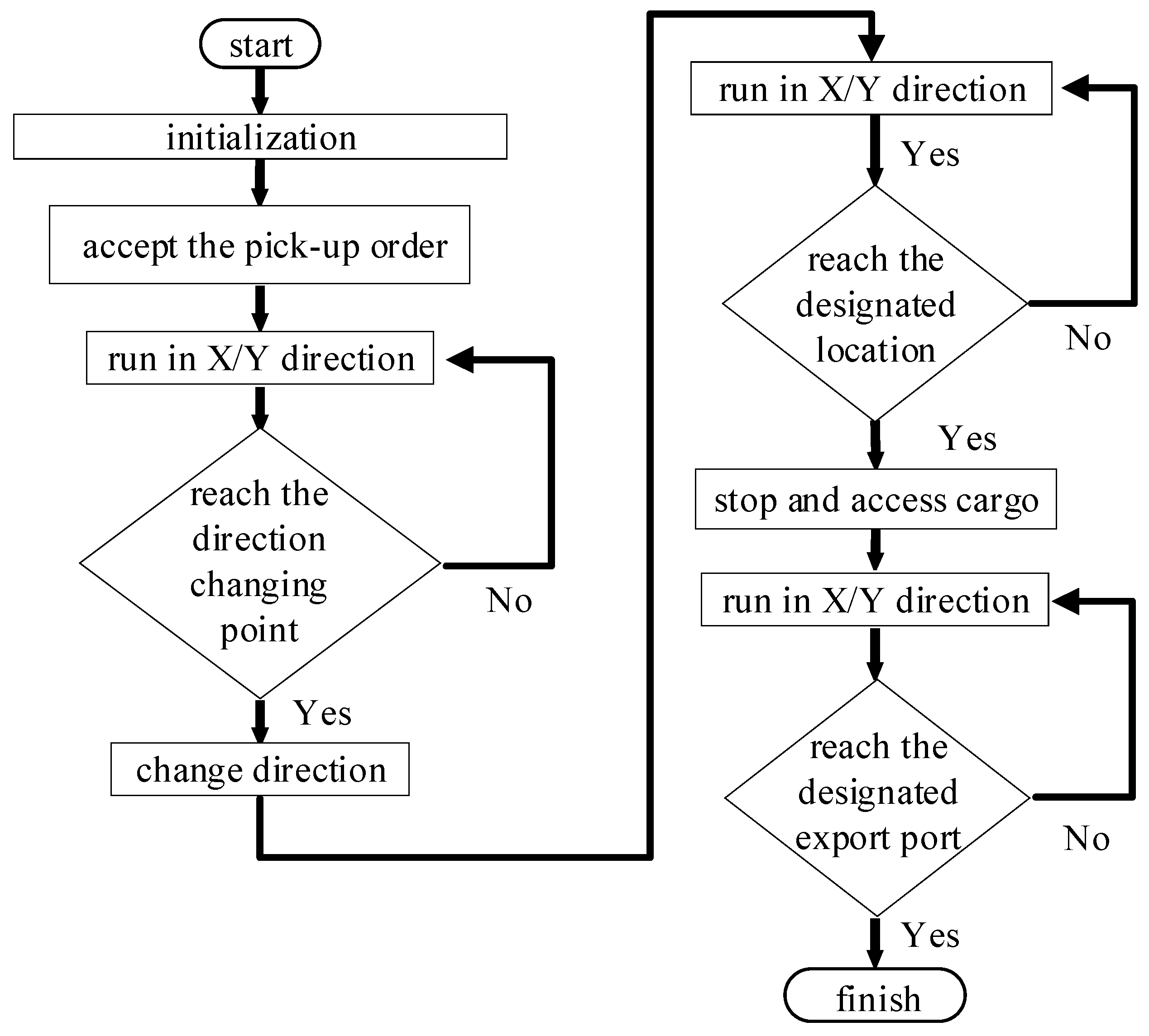
The vehicle can run in X/Y direction, change direction, and access goods. Taking the pick-up task as an example, the vehicle needs to achieve the following action requirements in operation:
- (1)
The host computer sends the pick-up location and related instructions to the shuttle. Upon receiving the instructions, the shuttle reaches the direction-changing point after driving a certain distance along the X/Y direction of the shelf track;
- (2)
With the information received by sensors, it is confirmed that the shuttle will break when it is about to reach the direction-changing point accurately, and then the vehicle will change direction;
- (3)
After the direction is changed, the shuttle travels along the X/Y direction to the pick-up location. When it is about to reach the designated location, it stops at the location accurately;
- (4)
After the shuttle stops at the cargo point, the telescopic mechanism moves the cargo to the vehicle;
- (5)
After picking up, the shuttle travels to the designated export port to complete the task.
The workflow of the shuttle is shown in
Figure 1.
It can be seen from the chart that the four-way shuttle runs in the X/Y direction during most working hours. Therefore, in order to avoid overturning, it is necessary to establish the overturning model of the running vehicle.
3.1. Symbols and Meanings for Establishing the Overturning Model of a Four-Way Shuttle Vehicle
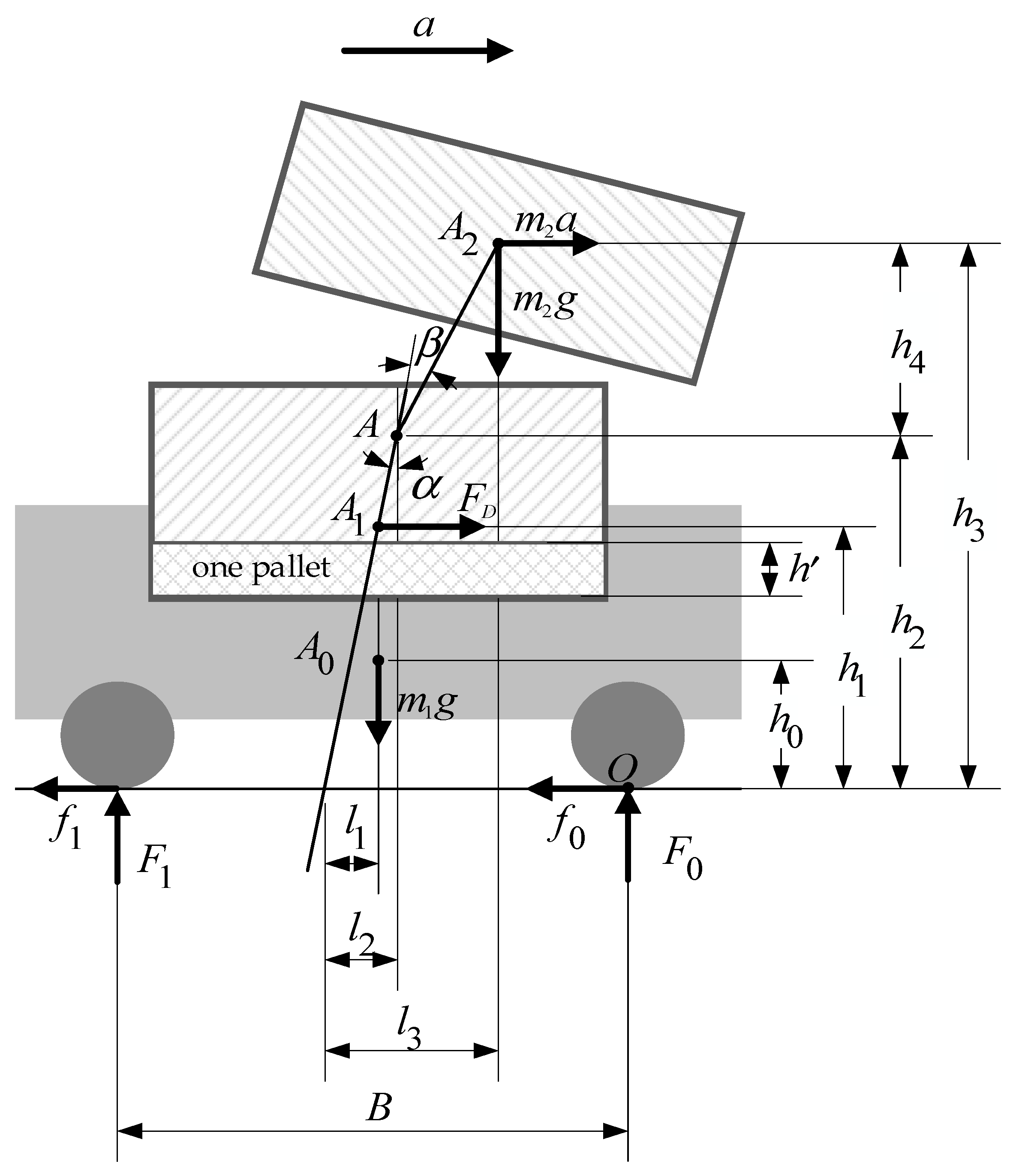
When carrying goods, the four-way shuttle vehicle not only needs to consider the role of the wheels, but also needs to analyze the force situation of the vehicle when carrying finished grain bags stacked in layers on pallets. In addition, during the transportation of grain bags, the shuttle vehicle experiences sudden changes in lateral load due to conflicting acceleration, resulting in changes in the load on the front and rear wheels. As a result, the vehicle’s centre of gravity also shifts, and the anti-overturning performance of the entire system also decreases. In the finished grain depot, the four-way shuttle car mainly transports finished grain bags. When the variety of finished grain is different, and the quality of the goods is constant, the volume of the goods varies. That is to say, when the shuttle car transports finished grain goods of the same quality and different categories, their critical overturning conditions are different. The symbols and meanings required for establishing an overturning model are shown in
Table 1.
3.2. Establishment of Overturning Model
When the four-way shuttle vehicle transports finished grain bags on pallets, the stacking method of the grain bags is a forward and backward staggered pattern [
20]. When analyzing the overturning performance of the goods and the vehicle as a whole, the shuttle vehicle and the goods mainly bear gravity, the normal reaction force of the track, and the acceleration forces caused by lateral acceleration. To simplify the problem, the following assumptions are made:
- (1)
Only the components that have a significant impact on the overturning performance of the shuttle vehicle, such as the wheels and cargo body, can be considered, and other parts that have a small impact on the overturning performance can be ignored;
- (2)
When the shuttle vehicle is not in motion, its center of mass, the center of mass carrying the goods, and the overturning center are on the same vertical plane;
- (3)
The supporting force on the wheels on both sides of the shuttle is applied at the center of the contact between the wheels and the track;
- (4)
The overturning of goods transported by shuttle vehicles is analyzed based on each layer.
The actual force situation of the four-way shuttle vehicle when carrying goods is shown in
Figure 2.
Taking the top cargo as the research object in the overturning mechanical model, the moment of the overturning point
is calculated as follows:
α and
β represent the inclination angles of the lower-level cargo and the overall vehicle body, as well as the inclination angles of the top-level cargo. According to common knowledge in cargo transportation, these two inclination angles must be within a very small range so that they can be ignored:
The height of the lower cargo is
, the height of the upper cargo is
, and the mass of the upper cargo is:
When the vehicle is in acceleration or deceleration, the reaction forces
F0 and
F1 that the track exerts on the wheels will change with the vehicle inclination, wheel deformation and wheel stiffness.
then
From relationship (2), (11), we can obtain
From relationship (1), (4), and (12), we can obtain
From relationship (4), (11), and (13), we can obtain
When analyzing the force acting on the entire grain bags and the vehicle, the external loads mainly include its weight, the driving force, and the track reaction force.
Taking the moment of the contact point
O, we have:
When there is no load,
; according to relationship (17), the critical overturning condition of the unloaded shuttle vehicle can be obtained:
When there is no load, the vertical height of the center of mass , the wheelbase of vehicle and the friction coefficient of the track are all constant, so the critical overturning acceleration is a constant. When the actual acceleration of the vehicle exceeds this value, the vehicle will have a hidden danger of overturning.
According to relationship (17), the critical overturning condition of the loaded shuttle vehicle can be obtained:
where
m2,
l1, and
l3 can be calculated by relationship (5), (12), and (14), respectively. Thus, the acceleration value of the critical overturning is closely related to the height of the grain bags, the mass of the vehicle and the grain bags, the type of grain, and so on. Therefore, it is necessary to have a comprehensive calculation of all relevant parameters under this critical condition.
4. Design of the Fuzzy PID Controller for Four-Way Shuttle Vehicles
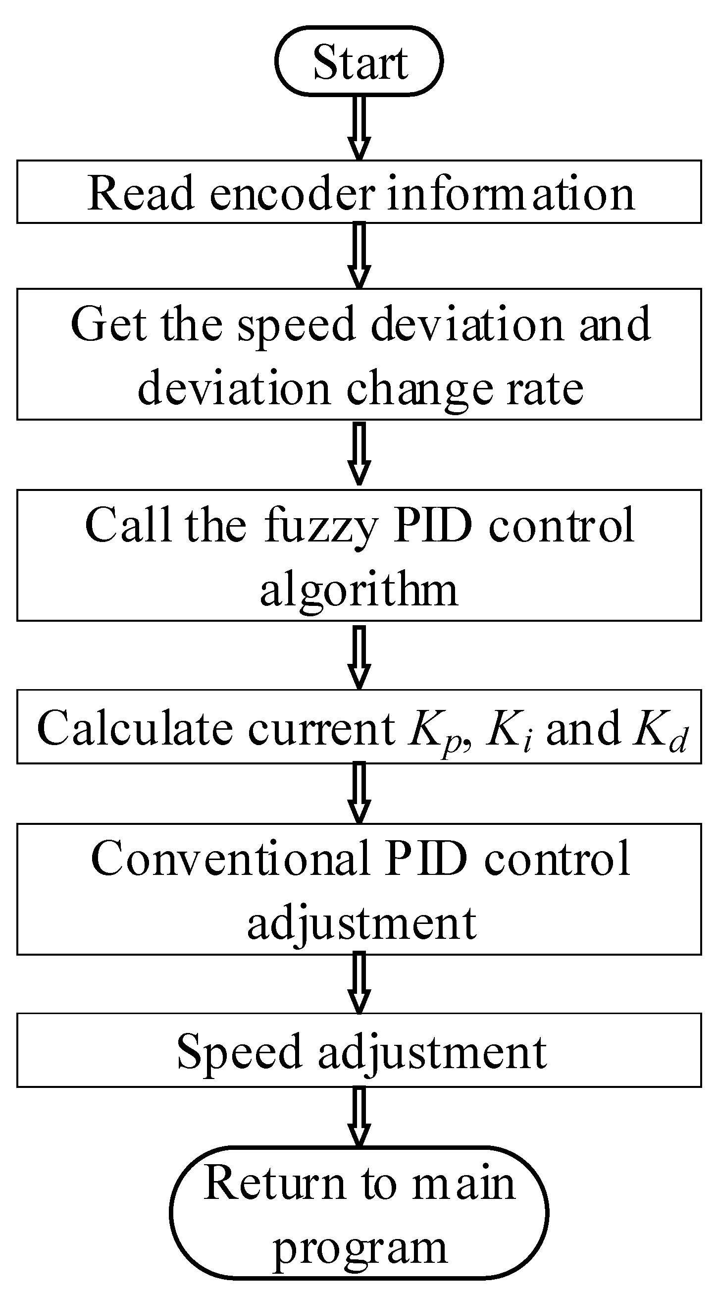
The critical overturning condition for the four-way shuttle vehicle under various load conditions is tied to acceleration. As operating conditions during acceleration and deceleration change dynamically, sensors are typically utilized to obtain the vehicle’s movement information, allowing for position and speed control in the X/Y direction during operation. Following the photoelectric conversion principle, a photoelectric encoder can convert the geometric displacement of the output shaft into a pulse signal, which has good anti-interference ability when measuring angle and displacement, and output the pulse signal stably. In order to study the speed of the four-way shuttle, the encoder is used to measure the number of pulses to obtain the rotation angle and speed of the motor shaft.
In order to control the speed of the shuttle accurately, the current correction is calculated by the PID control algorithm with the speed deviation and the deviation change rate as the reference input. Then the parameters of
Kp,
Ki, and
Kd are calculated to adjust the running speed of the shuttle in real-time under different motion states. The flow chart of running control in the X/Y direction of the four-way shuttle is shown in
Figure 3.
Part of the program of the motor speed control is shown in
Table 2.
From the overturning model of the four-way shuttle vehicle, it can be seen that the critical overturning condition of the vehicle is related to acceleration. Therefore, the optimal setting value of the vehicle’s acceleration should comply with the anti-overturning condition of the vehicle, which determines the acceleration control strategy under no-load and load conditions. Given the four-way shuttle vehicle’s dynamic and real-time speed variations in different working conditions, a fuzzy PID control is implemented to eliminate external disturbances during the acceleration and deceleration stages. This method enables real-time and quick tracking of input signals to the system, ensuring a smooth and prompt response to the set speed and acceleration. This approach aims to prevent possible overturning incidents of the vehicle under various working conditions.
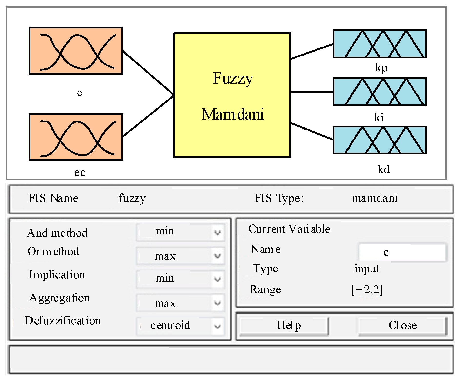
As such, a two-dimensional fuzzy controller with two inputs and three outputs was constructed to regulate the DC motor speed by adjusting the PWM pulse, and to detect the speed and acceleration of the vehicle by an encoder. The inputs were the deviations between the actual speed and the set speed e, and the deviation change rate ec were fuzzified and put into the fuzzy controller to obtain the fuzzy control variables through inference calculation. The fuzzy controlled variables were defuzzified to obtain the controlled variables of Kp, Ki, and Kd. Ki represents the integral coefficient, Kd represents the differential coefficient, and Kp represents the proportional coefficient. In addition, the conventional PID control method was used to correct the parameters and adjust the vehicle speed in real time.
- (1)
Fuzzifying the input and output variables:
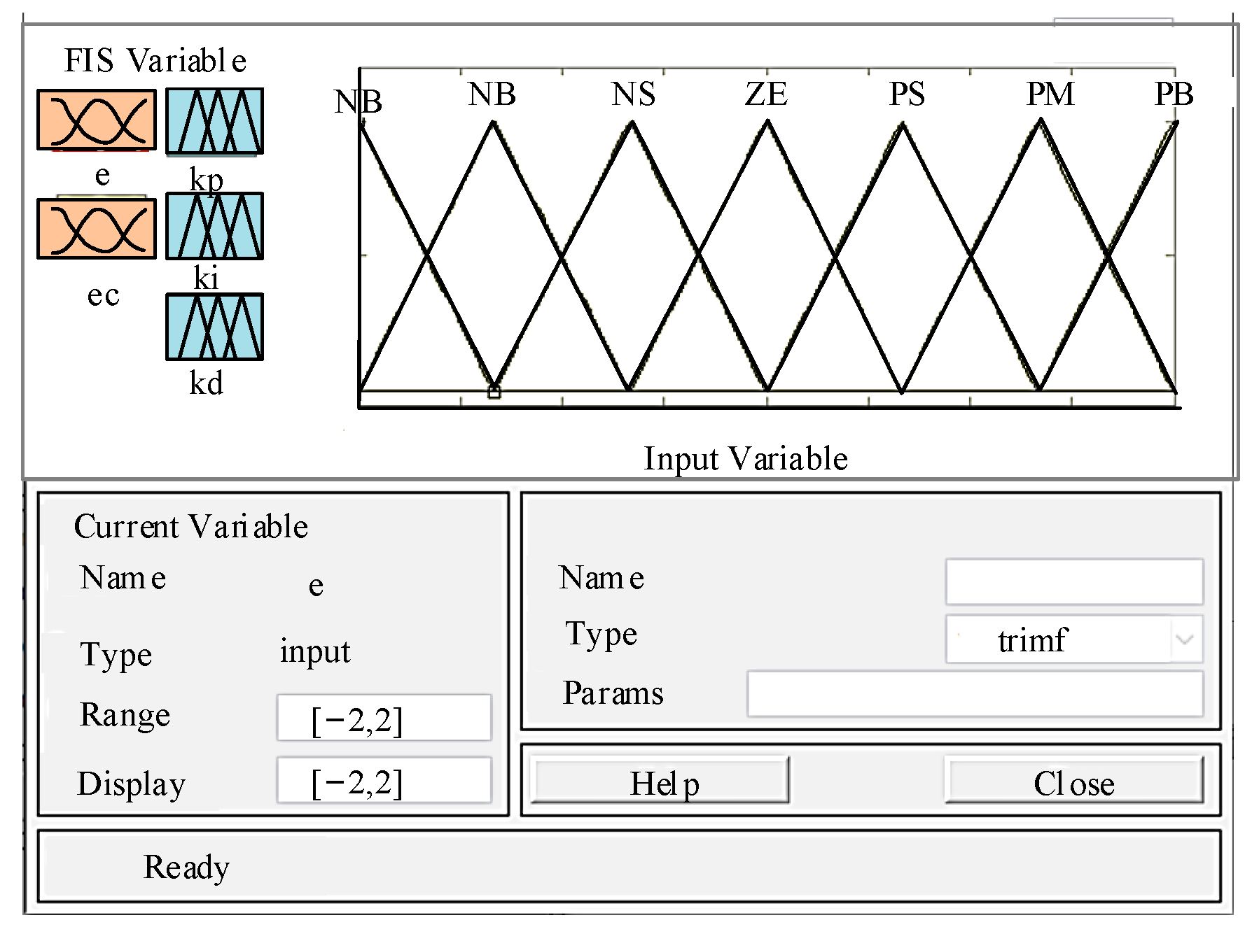
Based on the control requirements of the closed-loop control system of the four-way shuttle vehicle, the basic domain range of each input and output parameter needs to be determined. The basic domain range of the actual speed deviation and the preset speed deviation e was [−0.1, 0.1], and the basic domain range of the deviation change rate ec was [−1, 1]. The output variables were Kp, Ki, and Kd. The basic domain range was divided into seven levels {−6, −4, −2, 0, 2, 4, 6}, and the fuzzy domain was set at [−6, 6]. The language variables used were NB (negative large), NM (negative medium), NS (negative small), ZE (zero), PS (positive small), PM (positive medium), and PB (positive large);
- (2)
Determining the membership function:
Many types of membership functions correspond to different fuzzy sets, among which triangular membership function, Gaussian membership function, and Z-shaped membership function are the most commonly used. The triangular membership function is applicable to many different types of fuzzy sets, and its membership curve can completely meet the requirements of researchers. Additionally, its calculation is straightforward; one only needs to determine the triangle’s vertex coordinates and compute the distance between a point and the triangle’s vertices to derive the point’s membership degree. In addition, the triangular membership function has good visibility and plays an important role in visualization processing. Therefore, we chose this function to construct fuzzy sets. The triangular membership function (as shown in
Figure 4) was adopted for its quick and accurate performance in the fuzzy numerical calculation for rapid speed adjustment of the vehicle;
- (3)
Establishing a fuzzy rule base:
The fuzzy control rules between the input and output variables (△
Kp, △
Ki, △
Kd) were designed for a quick and better response of the control system and the least speed deviation of the vehicle. The fuzzy control rules for △
Kp, △
Ki, △
Kd are shown in
Table 3,
Table 4 and
Table 5, respectively;
- (4)
Fuzzy reasoning and defuzzification:
The fuzzy logic between the three output variables (△
Kp, △
Ki, △
Kd) and
e,
ec was obtained by the Mamdani fuzzy inference based on the fuzzy control rules. However, the variables obtained after the fuzzy reasoning could not be directly used for controlling the executing mechanism. Therefore, the centroid method with high precision and smooth output was adopted for accurate control variables. The relationship for defuzzification using the centroid method is as follows:
where,
,
, and
are the domain of fuzzy control quantity, the membership value of
, the fuzzy set, and the correct quantity after defuzzification, respectively [
22].
Finally, the parameter values of the PID controller are calculated according to relationship (21).
where,
Kp0,
Ki0 and
Kd0 are the initial values of PID parameters, and △
Kp, △
Ki, and △
Kd are the adjusted values by fuzzy reasoning based on
e and
ec [
23].
5. Simulation Verification
5.1. The Establishment of Simulation Model
The input and output variables, namely
e and
ec, and △
Kp, △
Ki, and △
Kd, were set in Simulink’s fuzzy inference system editor. The basic structure diagram of the fuzzy controller is shown in
Figure 5.
The input and output variables were set as triangle membership functions in the editor. The basic structure diagram of the fuzzy controller is shown in
Figure 6. In the fuzzy rule editor, 49 fuzzy rules were imported according to the fuzzy control rule table established in this paper.
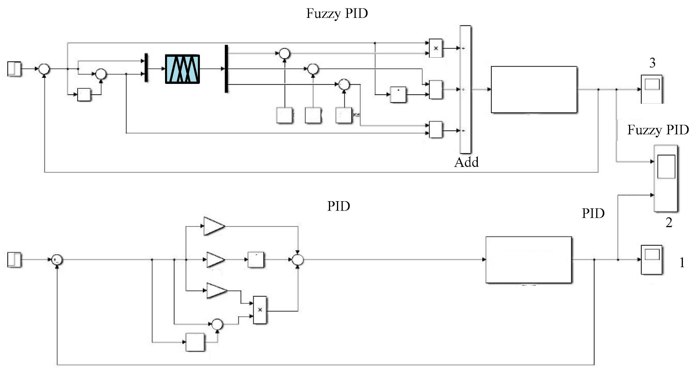
For the purpose of performance comparison, a simulation model for the speed control of a four-way shuttle vehicle was built based on fuzzy PID and conventional PID in Matlab/Simulink (as shown in
Figure 7).
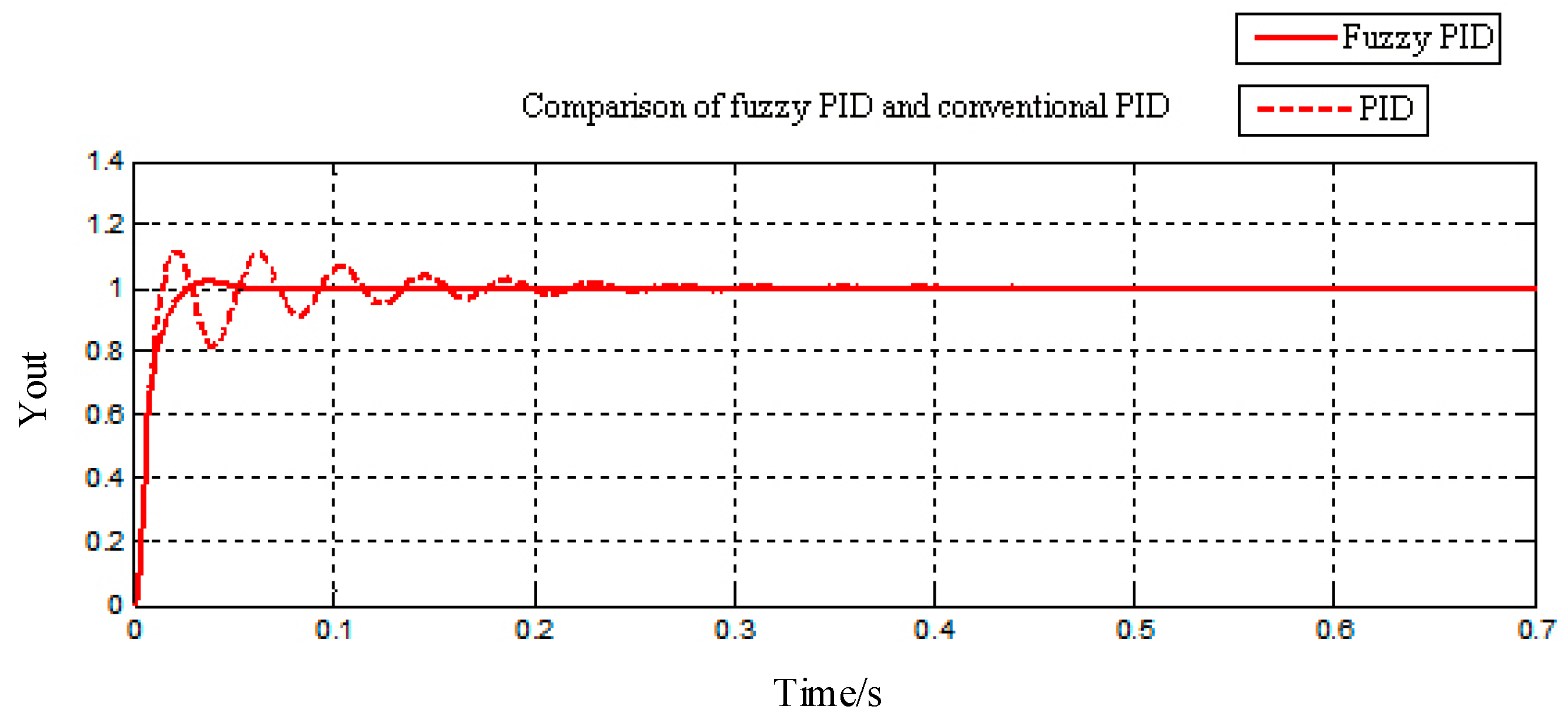
5.2. Simulation Results
In the Simulink software, the parameters were set as follows: the sampling time was 0.7 s, the initial deviation was 0.14 m/s, the deviation change rate was 0 m/s
2, and the vehicle’s running speed was 1 m/s. During the simulation experiment, the fuzzy PID controller and the conventional PID controller were used, respectively, and the results show the difference in speed control in
Figure 8.
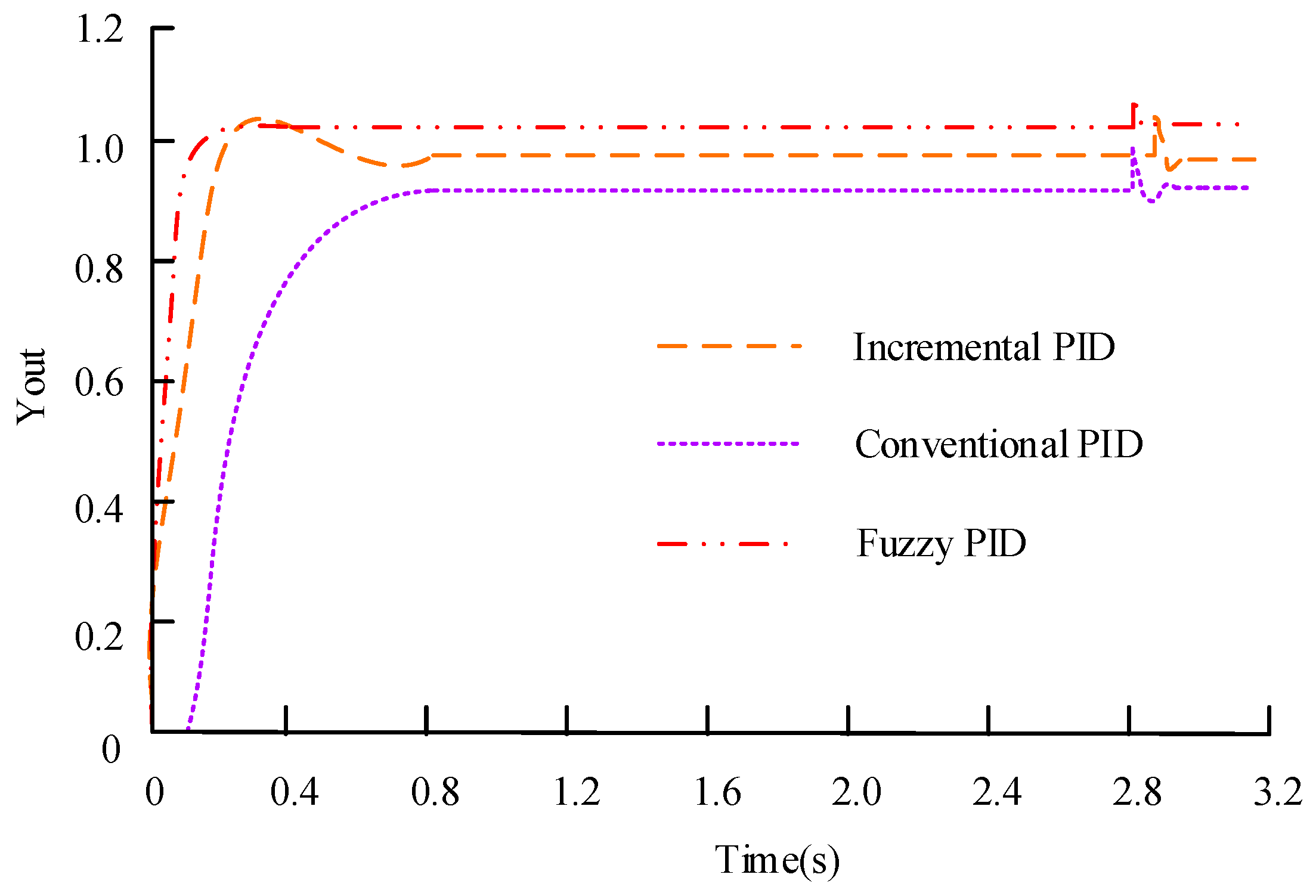
Figure 8 shows that within a control time of 0.1 s, the traditional PID controller experienced four significant fluctuations. After 0.1 s, the traditional PID control gradually stabilizes and only reaches a stable state after 0.2 s, indicating poor stability and slow adjustment speed. On the other hand, the fuzzy PID controller reached a very stable state within 0.1 s, and there were no fluctuations after 0.1 s. At the same time, it can be observed that, with an overshoot of 2% and an adjustment time of 0.06 s, the fuzzy PID controller is quicker in response and convergence compared with the conventional PID control, whose overshoot is 11% and adjustment time is 0.45 s. To further verify the superior performance of the proposed fuzzy PID control in the speed control of the four-way shuttle vehicle, it was compared with the incremental PID algorithm and conventional PID control methods in an interference environment. The results are shown in
Figure 9.
Figure 9 shows that both incremental PID control and conventional PID control have significant fluctuations around 2.8 s, with relatively large amplitude, indicating that these control methods have low adaptability and insufficient anti-interference ability. At the same time, it can be observed that the incremental PID control converges for about 0.3 s, while the conventional PID control converges for about 0.8 s. The proposed fuzzy PID control method has small fluctuations and converges within approximately 0.1 s. It has strong adaptability, strong anti-interference ability, fast adjustment speed, and basically achieves no overshoot of the system. Therefore, it performs better in controlling the speed of the four-way shuttle.
6. Discussion
Grain, an important resource for ensuring people’s livelihoods, is an important strategic material for maintaining national security and social stability. Finished grain warehouses are an important carrier for storing finished grain, directly determining the storage and circulation capacity. As the four-way shuttle car operates on the rack track while transporting complete pallets of finished grain goods, it must perform smoothly while also withstanding heavy loads. Additionally, the vehicle’s anti-overturning stability performance must be considered to prevent safety hazards caused by the grain bags during acceleration, deceleration, or impact. In response to the issue of the four-way shuttle vehicle being prone to overturning when subjected to impact during acceleration and deceleration, a critical overturning condition is identified by establishing an overturning model for the four-way shuttle vehicle during cargo operation. This condition is applied to speed control to improve the anti-overturning stability of the shuttle vehicle. In addition, in order to further improve the anti-interference ability of the control system, the fuzzy PID algorithm is used for speed control, and comparative simulation models of fuzzy PID and conventional PID are established in MATLAB/Simulink. The results showed that the overshoot of the proposed fuzzy PID controller was 2%, and the adjustment time was 0.06 s. In an environment with interference, the fluctuation between incremental PID control and conventional PID control occurred in 2.8 s, with incremental PID control converging in about 0.3 s and traditional PID control converging in about 0.8 s. The fuzzy PID control method converged in approximately 0.1 s, having strong adaptability and anti-interference ability. Although the design of the four-way shuttle control system meets functional requirements, there is less consideration given to safety protection, path optimization during driving, and energy consumption issues. Therefore, the control system still needs further optimization.
7. Conclusions
As an important piece of equipment in the automatic storage system for processing grain, the four-way shuttle truck’s anti-overturning stability is crucial. On this basis, a vehicle overturning mechanics model is established to address the factors that affect vehicle anti-overturning stability and the critical conditions for vehicle non-overturning. The fuzzy PID control method is used to control the operating speed of the shuttle vehicle. The results showed that within a control time of 0.1 s, the traditional PID controller experienced four significant fluctuations before reaching a stable state after 0.2 s. Meanwhile, the fuzzy PID controller reached a stable state within 0.1 s, with no fluctuations after 0.1 s. The fuzzy PID converged within 0.05 s, while the overshoot of traditional PID control was 11%, and the adjustment time was 0.45 s. In an interference environment, the incremental PID converged around 0.3 s, while the fuzzy PID improved by 0.2 s, proving that the proposed control method had better speed control performance and significantly improved the system’s anti-interference performance. However, research has not given sufficient consideration to energy consumption and safety issues, so it is necessary to improve the level of automation and efficiency further.


