Article

Analytical Model of Hydraulic Fracturing for Low Permeability Hot Dry Rock Reservoirs and DEM Simulation Base on Fluid-Solid Coupling

1
College of Electrical Engineering, Xi′an Shiyou University, Xi′an 710000, China
2
State Key Laboratory for Performance and Structure Safety of Petroleum Tubular Goods and Equipment Materials, CNPC Tubular Goods Research Center, Xi′an 710000, China
3
School of Science, Qingdao University of Technology, Qingdao 266520, China
*
Author to whom correspondence should be addressed.
Processes 2023, 11(4), 976; https://doi.org/10.3390/pr11040976
Submission received: 23 October 2022 / Revised: 9 March 2023 / Accepted: 16 March 2023 / Published: 23 March 2023
(This article belongs to the Special Issue Risk Assessment and Reliability Engineering of Process Operations)

Abstract

:
The formation of a rich underground-seam network is the key problem in the development of low-permeability hot dry rock (HDR) resources. Considering the lack of macroscopic continuum theory to study hydraulic fracturing having preset fracture-interface element, the particle-flow method of micro-mechanical discrete-element theory is introduced to simulate the mechanical behavior of hydraulic fracturing for HDR low permeability reservoirs. The reservoir is simulated as a round particle; the fracturing fluid movement is described by the seepage field equation, and rock movement is described by the displacement field equation. Finally, the particle-flow numerical model of hydraulic fracturing for HDR low permeability reservoirs is established under the condition of fluid-solid coupling: the model contains two parts (rock and fracture). Based on the parallel-bond model, a definition of micro-fractures of hydraulic fracturing is given. The relation between the fracturing effect and influence parameters is discussed. The results show that the fracture-initiation pressure is proportional to the magnitude of minimum horizontal stress, particle normal-contact stiffness, and particle normal- and tangential-connection strengths; the pressure is also independent of maximal horizontal stress and tangential contact stiffness. At the same time, the formation temperature of dry hot rock will reduce the strength of the rock, so particle-flow numerical models of hydraulic fracturing in different temperatures are discussed. Results show that fracture length and width show a trend of increase before decrease with the increase of injection pressure, an inverse relationship with minimums horizontal principal stress, and a positive relationship with HDR reservoir permeability.

1. Introduction

Hot dry-rock geothermal energy is clean, has abundant reserves, and has great development potential [1,2,3]. Therefore, SINOPEC has established the first dry hot-rock geothermal resources development demonstration base [x-3] in Gonghe basin, Qinghai Province, China [4]. However, the development of engineering technology for HDR reservoirs is challenging, especially during the process of exploitation. Hydraulic fracturing needs to increase the flow capacity between injection wells and production wells to achieve the purpose of extracting geothermal energy, which is a difficult technology to develop [5,6].
Hydraulic fracturing is the most commonly used method of stimulating reservoirs of low permeability [7]. Essentially, the fracturing fluid is injected into the reservoir and generates a hydraulic fracture. This process is very complex, comprising the fluid-solid coupling between seepage field and stress field. Scholars have made a series of achievements in the study of reservoir fracturing. For example, Zhou et al. [6] used experiments to study the hydraulic fracture propagation of HDR resources. Li Guanglin [8] studied the physical properties and permeability of HDR under hydraulic fracturing, finding that the reservoir′s physical properties and permeability are different under different temperatures. According to the research conducted by Jinze Xu et al. (2017) [9], the real gas model was successfully validated through the use of molecular simulation and experimental data, resulting in outstanding outcomes. The study revealed that the laminar slip-flow conductance increases as the intermolecular collision strength increases, while an increase in molecule-wall collision strength leads to an increase in Knudsen diffusion conductance, ultimately improving transport efficiency. Furthermore, the apparent permeability reflects the improvement in the model′s performance. Based on flow regime analysis, Jinze Xu et al. (2019) [10] have developed a gas apparent-permeability model for high-pressure tight sandstone reservoirs that establishes a connection between molecular kinetics, gas transport mechanisms, and apparent permeability. Hagoort et al. [11] established a fracture-propagation model for hydraulic fracturing and considered that the injection rate and pore displacement rate have an important influence on fracture propagation. Settari et al. [12] established a pseudo-three-dimensional hydraulic-fracturing model and concluded that the stress difference between the reservoir and the adjacent barrier is an important factor in controlling the vertical fracture penetration. Rahim et al. [13] introduced a three-dimensional concept to establish a two-dimensional fracture-propagation model for reservoirs. Zillur et al. [14] applied the finite-difference method to analyze the effects of various parameters on the reservoir-fracture effect. Wei et al. [15] established a horizontal well hydraulic-fracturing fracture-propagation model. Cheng Yuanfang et al. [16] discussed the relationship between horizontal wellbore orientation, horizontal principal stress, and fracture propagation from a macroscopic perspective. Zhang Guangqing et al. [17] established a hydraulic fracture-space steering model near the horizontal wellbore and verified the conclusions using laboratory experiments. Zhang Guangming et al. [18,19] used ABAQUS software to establish a three-dimensional numerical model of reservoir hydraulic fracturing; they obtained fracture morphology, pore-pressure distribution, and stress and strain distribution results of reservoirs at different times. Although the above scholars have achieved a series of results, the research focuses on the macroscopic mechanical mechanism of hydraulic fracturing, and the hydraulic fracturing mechanism has not been studied from the perspective of meso-mechanics. At the same time, at present, for the macroscopic-mechanism research of hydraulic fracturing, finite-element or finite-difference methods are commonly used. Such methods need to preset the fracture-interface unit, that is, the fracture can only expand along the set cell interface; such an interface is necessary for the processes of hydraulic fracturing and fracture-propagation orientation of a gap to work. In this case, the shape of the fracture obtained must be ideal.
The particle-flow method is based on molecular dynamics, and used to study the mechanical properties and behaviors of media. Boundary walls are used to constrain the basic elements. The particle-flow method only needs to define the micro-mechanical parameters for particles and bonds, and does not need to define the constitutive relationship and corresponding parameters of materials, which can reflect the macro problems. PFC follows the discontinuous-medium theory, and the movement between its basic units does not need to meet the constraint of the deformation-compatibility equation, but only needs to meet the balance equation. The contact force and relative displacement between particles are controlled through the built-in physical equation, and the physical equation will show linear or nonlinear laws due to the distribution between particles and the change of contact force, so that the movement between units is constrained.
The particle-flow method in mesoscopic discrete elements belongs to the category of discontinuous-medium mechanics. The particles and the presence of simulated particulate matter are not directly related, and the method is only a way to describe the properties of the medium [20,21]. The core ideas of the method are to discretize the simulated medium into a series of rigid particles and to simulate the specific mechanical behavior of the actual material by studying the motion of the particles [22]. The particle-flow theory can simulate the reservoir hydraulic-fracturing process by introducing the particles parallel to the constitutive model; this constitutive model allows the particles to contact the joint to create fractures [23,24,25], which provides conditions for simulating the fracture initiation and propagation of the reservoir fracture. Yang [26] used PFC software to carry out the fluid solid-coupling analysis of sandy, tunnel-end soil and its stability.
The biggest difference between the particle-flow method and the finite-element method, or the finite-difference method, for studying hydraulic fracturing is that the method does not need to set the fracture interface unit, so the simulated fracture is closer to the actual fracture shape. Since the particle-flow method can study the deformation and evolution process of rock mass without constitutive relation, this method has been widely used in geotechnical engineering, but its effect on reservoir hydraulic fracturing has not been studied. Considering that current scholars have a less detailed numerical simulation of the hydraulic fracturing process in the reservoir-fracturing fluid-solid coupling environment, we introduce the particle-flow theory, which establishes the particle-flow analytical model of hydraulic fracturing fluid-solid coupling from the mesoscopic point of view, and give a definition of reservoir hydraulic-fracturing fracture based on the parallel connected-constitutive model. This method has some significance for the widening of low permeability reservoir hydraulic fracturing theory.

2. Fluid-Structure Coupling Model

2.1. The Basic Postulates of HDR Resources

The HDR fracture reservoir can be simplified as a rock and fracture dual-medium model. The rock block has low permeability so the artificial fracture-network formed by hydraulic fracturing constitutes the main flow channel of fluid. HDR resources have very high temperatures, but at the same time, HDR resources have high pressure [27,28], so we assume that the water in the deep-underground rock mass is impossible to vaporize. Therefore, it can be assumed that the reservoir is saturated by single-phase water, and the flow of water is laminar, which obeys Darcy′s law. In order to simplify the calculation, we also consider that the rock mass and fracture are always in an elastic state and satisfy the hypothesis of small deformation.

2.2. Mathematical Model of Fluid-Structure Coupling

2.2.1. Mathematical Model of Fluid-Structure Coupling in Rock Section

Considering the constitutive relation of effective stress, the equilibrium-differential equation and the displacement relation (the displacement field equation of bedrock) can be obtained. Based on the mass-conservation equation and Darcy′s law, the seepage field equation can be obtained. Based on the above, the mathematical model of fluid-structure coupling in rock section can be obtained [26]:
σ x x + τ y x y + τ z x z + F x = 0 τ x y x + σ y y + τ z y z + F y = 0, τ x z x + τ y z y + σ z z + F z = 0
E 2 1 + ν u i , j j + E 2 1 + ν 1 2 ν u j , j i α b p , i + F i = 0,
3 ν u ν 1 + ν u 1 2 ν ε v t + 9 1 + ν 1 2 ν u ν u ν E B 1 + ν u 2 1 2 ν p t = B k 2 p,
Above, σij is stress tensor; u is displacement; Fi is body force; E is Young′s module; ν is Poisson′s ratio; αb is Biot coefficient. P is pore pressure; νu is drainage Poisson′s ratio of solid components; B is skempton coefficient; εv is body strain; and k is the inherent permeability of continuous medium, t is time.

2.2.2. Mathematical Model of Fluid-Structure Coupling in Fracture Section

For hydraulic fracture, it is treated as a discrete fracture. So we consider only two displacement values, tangential displacement and normal displacement, and the displacement field equation can be obtained. The equation of fracture-seepage field can be obtained according to the literature [28]. Based on the above, the mathematical model of fluid-structure coupling in the fracture section can be obtained:
U n = σ n p k n , U s = σ s k s ,
S f p t τ k f η p + ε v f t + k f d f η p n = 0,
where Un, Us are normal and tangential displacement of fracture, respectively; σn, σs are normal and tangential stress of fracture, respectively; kn, ks are normal and tangential stiffness of fracture, respectively; df is fracture width; Sf is the fracture water storage coefficient, Sf = 1; Kf is fracture permeability; εvf is the volume strain of the fracture surface; ∇τ is derivation along the tangential direction of fracture; η is the dynamic viscosity coefficient of the fluid.

2.3. Hydraulic Fracturing in DEM Simulation Considering Fluid-Structure Coupling

Hydraulic fracturing of HDR low-permeability reservoir is a complex process of coupling of fracturing fluid and reservoir. In DEM (Discrete Element Method) simulation, the circular-particle discrete element is used to simulate the reservoir (see Figure 1). It is assumed that the flow pipe of fluid exists in indirect contact with particles (see the black lines in Figure 1). The unit is set in the model that can store the pressure (see the red area in Figure 1) and we describe them as a fluid region. The black solid circles are the center of the fluid regions. The white lines represent the contact between particles.

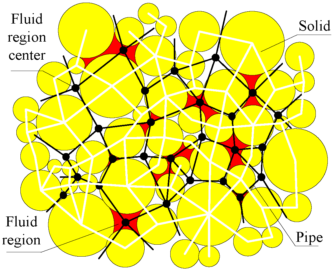
2.3.1. Pressure Calculation in Fluid Region

PFC2D software sets the flow pipe with a length of L and a radius of rb. Then the flow rate q in the pipe per unit thickness is [29]:
q = k r b 3 p i p j L ,
where pipj is the pressure difference between adjacent particle i and particle j.
It can be seen from the above formula that the pipe radius rb will affect the flow of the fluid region. In the fluid-structure coupling calculation, the pipe radius rb is related to the inter-particle force, and the calculation formula can be written as follows:
r b = r b 0 + λ d b ,                 F > 0 r b 0 F b F + F b ,                 F < 0 ,
where rb0 is the pipe radius when the indirect contact force of particles is 0; λ is the normal distance scaling factor; db is the normal distance between particles; Fb is the normal force when the pipe radius is rb0/2. F is the current normal contact force.
In the time stepΔt, the pressure increment Δp in the fluid domain is:
Δ p = K f V d q i Δ t Δ V d ,
where Kf is the volume modulus of fluid; Vd is the volume of the fluid domain; qi is the flow rate of the ith pipe on the fluid domain; ΔVd is the volume change of the fluid domain caused by force.

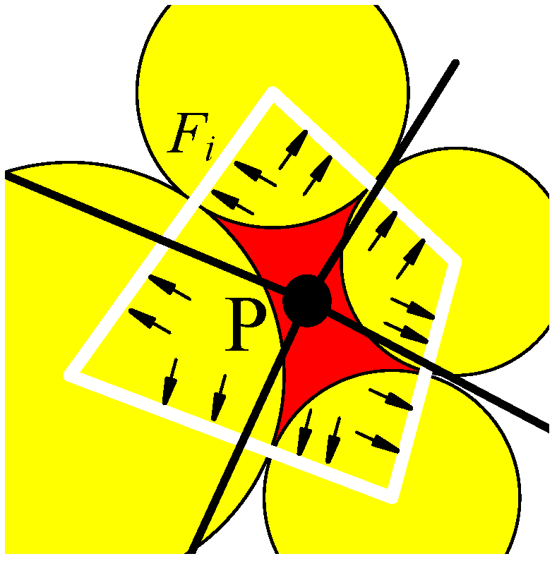
2.3.2. Analysis of Interaction Force between Fracturing Fluid and Reservoir Particles during Hydraulic Fracturing

In the discrete-element simulation of hydraulic fracturing of HDR low permeability reservoir, it is assumed that the fracturing fluid is an incompressible fluid with constant density, Fiave is the average force of fracturing fluid on particles per unit volume, and the calculation formula is as follows:
F i a v e = j = 0 N F j / j = 0 N V j ,
where N is the number of particles in the unit volume; Vj is the volume of particle j; Fj is the fluid pressure on particle j, which can express as t:
F j = P n j s ,
where P is the fluid pressure on the fluid domain around particle j; nj is the unit vector of the external normal of the line between adjacent contact particles; s is the distance from the center of the corresponding particle to the contact point, refer to Figure 2 for details.

2.3.3. Particle Motion Equation Considering the Action of Fracturing Fluid

While considering the interaction of the fracturing fluid with the particles, the movement of the reservoir particles still follows Newton′s second law [30], and the corresponding equation of motion is:
m p d v p d t = m p g + c f c n + S p P n d S p ,
J p d ω p d t = c r c f c τ + r S p P τ d S p ,
where mp is the particle mass; g is the acceleration due to gravity; vp is the particle velocity; Jp is the particle moment of inertia; ωp is the particle rotation speed; [fc]n, [fc]τ are the contact normal and tangent forces between the particles at the contact c (c = 1, 2, …), respectively; rc is the direction vector of the particle contact position to the center of the particle; r is the radius vector; Sp is the particle surface area; [P]n, [P]τ are the components of the normal and tangent directions of the fluid pressure.
The integral term in Equations (11) and (12) contains the resultant force and resultant moment of the fracturing fluid acting on the particles p. For particles p in a given volume Vp, the integral term in Equation (11) can be expressed as fracturing-fluid mean fluid stress τfave and fracturing-fluid particle-interaction force Fiave in the form:
S p P n d S p = p f x + p f y V p + F i a v e 1 n V p ,
The above formula is the drag force applied to the particles by the fracturing fluid. Similarly, the integral term in Equation (12) can be expressed as:
r S p P τ d S p = r g V p x + y τ f a v e ,
where rg is the direction vector of the centroid and the centroid of the particle.

3. Definition of Hydraulic Fracturing Micro-Fracture Based on Particle Contact Connection Model

When using the particle-flow method to simulate the hydraulic-fracturing behavior of low-permeability reservoirs, it is necessary to set the connection between adjacent particles and to determine whether the connection is invalid by establishing the strength-failure criterion of the connection. Micro-fractures are produced while the connection disappears. Under the action of the fracturing fluid, the low-permeability reservoir forms a plurality of interpenetrating micro-fractures in a certain local area, that is, a fracturing fracture is formed macroscopically. Using PFC software, only the parallel connection model in the particle-contact constitutive model can form microfractures.
Five parameters can be used to describe the particle-contact parallel-connection model: normal stiffness kn, tangential stiffness ks, normal strength σc, tangential strength τc, and connection radius R. The total contact force and moment for defining the parallel connection are F and M, respectively, and the contact force F is decomposed along the contact surface into a normal component and a tangential component:
F = F n + F s ,
Within a time step Δt, the elastic force increments ΔFn, ΔFs and the elastic moment increment ΔM can be expressed as:
Δ F n = k n A V n Δ t ,
Δ F s = k s A V s Δ t ,
Δ M = J ω j ω i / Δ t ,
where, A is the contact connection area; Vn and vs. are the relatively normal and tangential contact velocities of the particle i and particle j, respectively; ωi and ωj are the angular velocities of the particle i and particle j, respectively.
After a time step Δt, the contact force and moment experienced by the parallel connection can be expressed as:
F t + Δ t : = F t + Δ F n + Δ F s ,
M t + Δ t : = M t + Δ M ,
Based on the determination of the contact force and moment of the parallel connection, the corresponding maximum tensile stress and shear stress can be expressed as:
σ max = F n / A + M R / I ,
τ max = F s / A ,
In the PFC discrete element software, the strength criterion for the parallel connection failure between particle i and particle j can be expressed as:
σ max σ c τ max τ c ,
It can be seen from the Formula (23) that when the maximum tensile stress and the shear stress received by the interparticle connection exceed the normal joint strength σc and the tangential joint strength τc, respectively, the connection disappears and micro-fractures are generated. Under the action of the fracturing fluid, the low-permeability reservoir will produce a plurality of micro-fractures that penetrate each other, and the micro-fractures further extend to form a hydraulic fracturing fracture.

4. DEM Simulation of Hydraulic Fracturing in HDR Low Permeability Reservoirs

4.1. Reservoir Hydraulic Fracturing DEM Model

The reservoir hydraulic-fracturing discrete-element model consists of a wall and a circular particle. The model length × width = 100 m × 100 m, and the generated model is shown in Figure 3.
Since the micromechanical parameters of the particles are difficult to determine directly when using the discrete-element model to simulate the macroscopic mechanical behavior of the reservoir fracture, it is necessary to first assume the micromechanical parameters of the particles, and then, using the biaxial numerical test in PFC, the macroscopic mechanical parameters of the rock to be fractured are compared repeatedly to obtain the micromechanical parameters of the particle flow [31]. The meso-mechanical parameters of the reservoir particles determined after repeated trials are shown in Table 1 below:
The micro-mechanical parameters in Table 1 correspond to the reservoir rock-elastic modulus of 14.20 GPa and Poisson′s ratio of 0.24, which is consistent with the macroscopic mechanical properties of the reservoir to be fractured. Corresponding to the basic parameters of the reservoir particles, the basic parameters of the fluid domain are shown in Table 2 below:

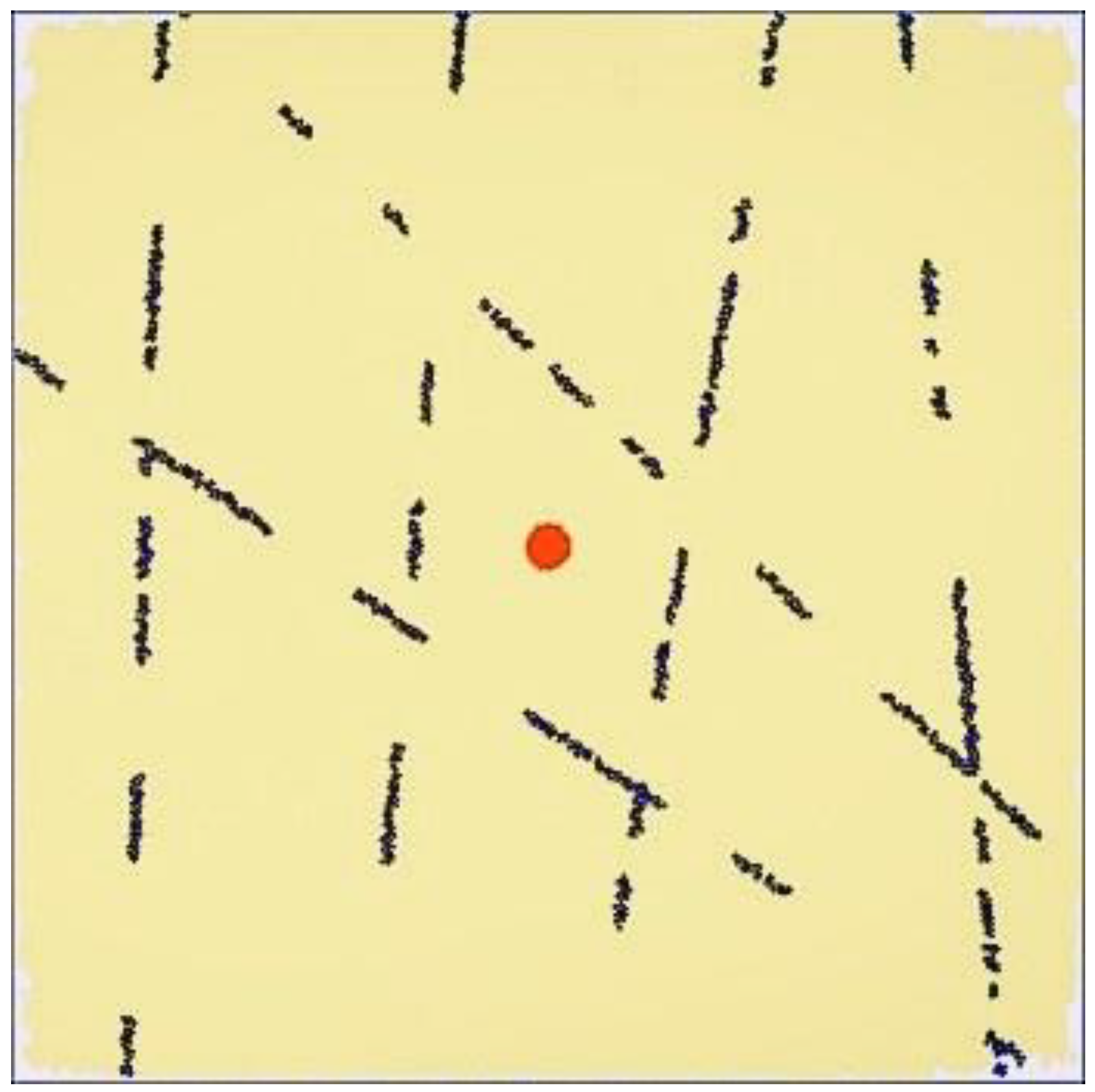
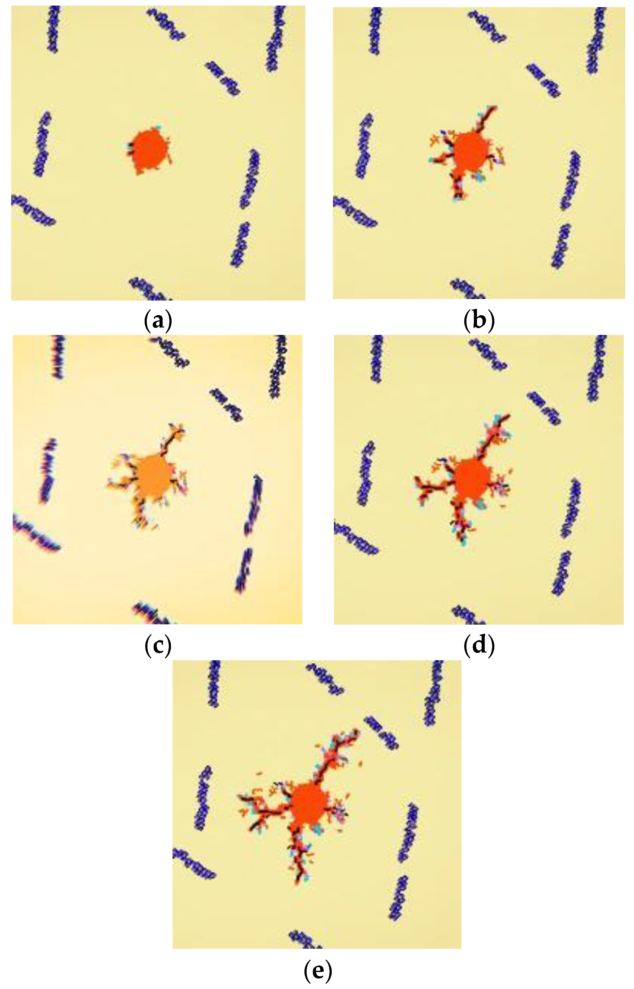
4.2. DEM Simulation Process

The HDR low-permeability reservoir-fracture propagation geometry under the injection pressure 45 MPa is shown in Figure 4 below.

4.3. DEM Simulation Result Analysis

The PFC software was used to simulate the effects of the following factors on the fracturing effect of the reservoir (such as fracturing pressure, seam length, slit width, etc.):
(1)
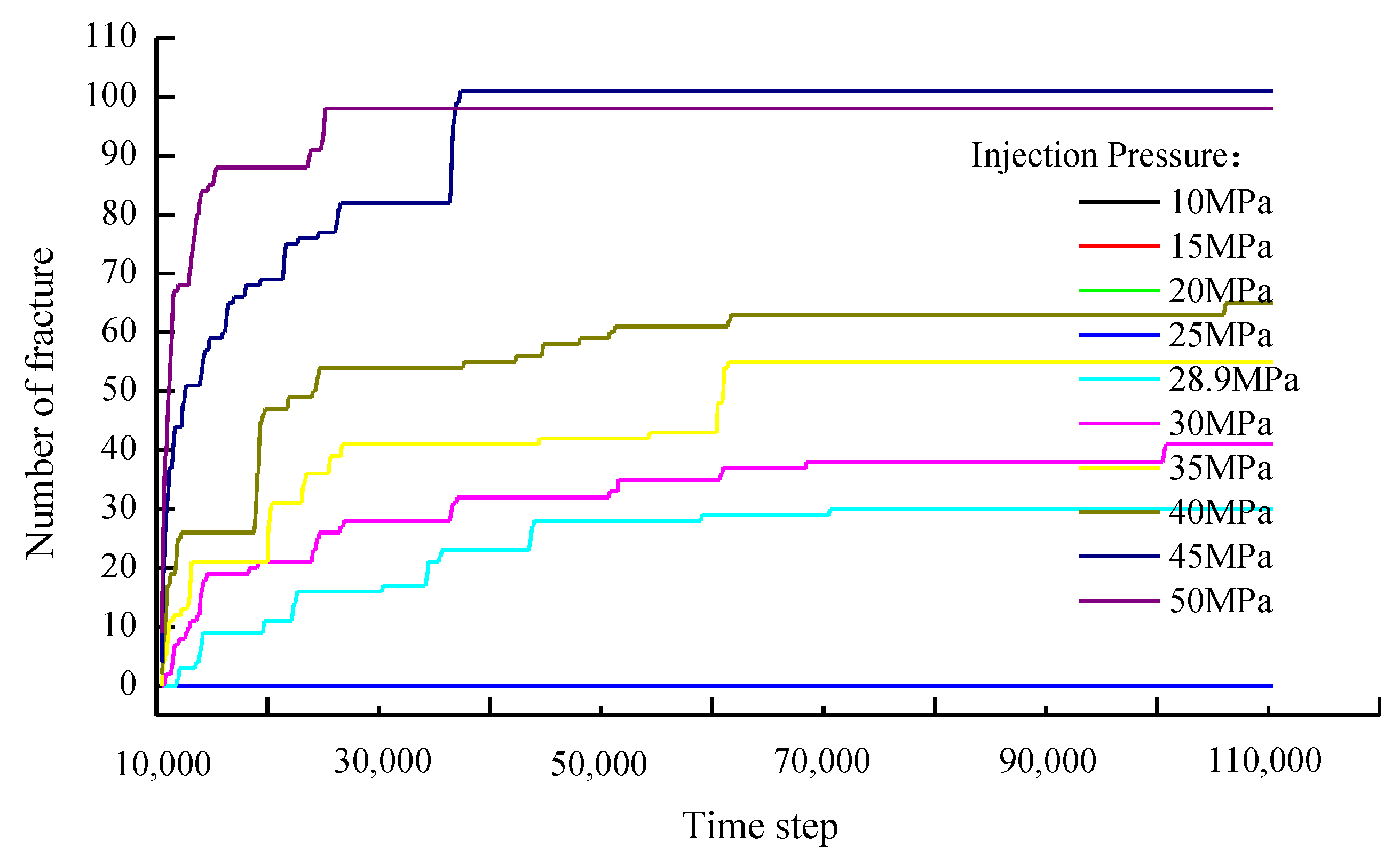
Under the condition that the meso-mechanical parameters of the reservoir particles are certain, we simulated the effects of different injection pressures on the fracturing effect. Wherein, the injection pressure varies from 25 MPa to 65 MPa, and each time increases by 5 MPa;
(2)
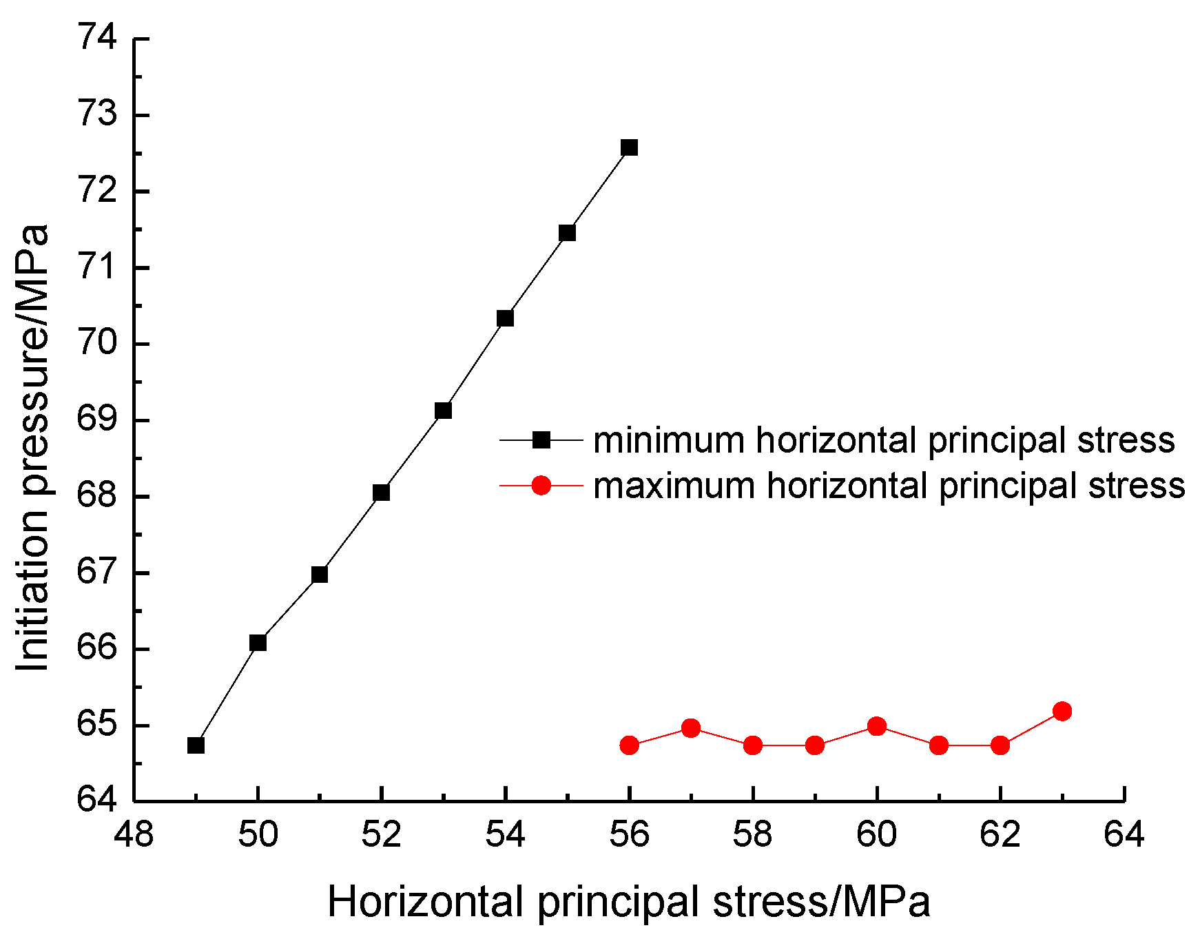
Under the injection pressure of 65 MPa, we simulated the effect of maximum and minimum horizontal principal stress on the fracturing effect. Wherein, the initial maximum principal stress is 56 MPa, and the minimum principal stress is 49 MPa; each increase is 1 MPa;
(3)
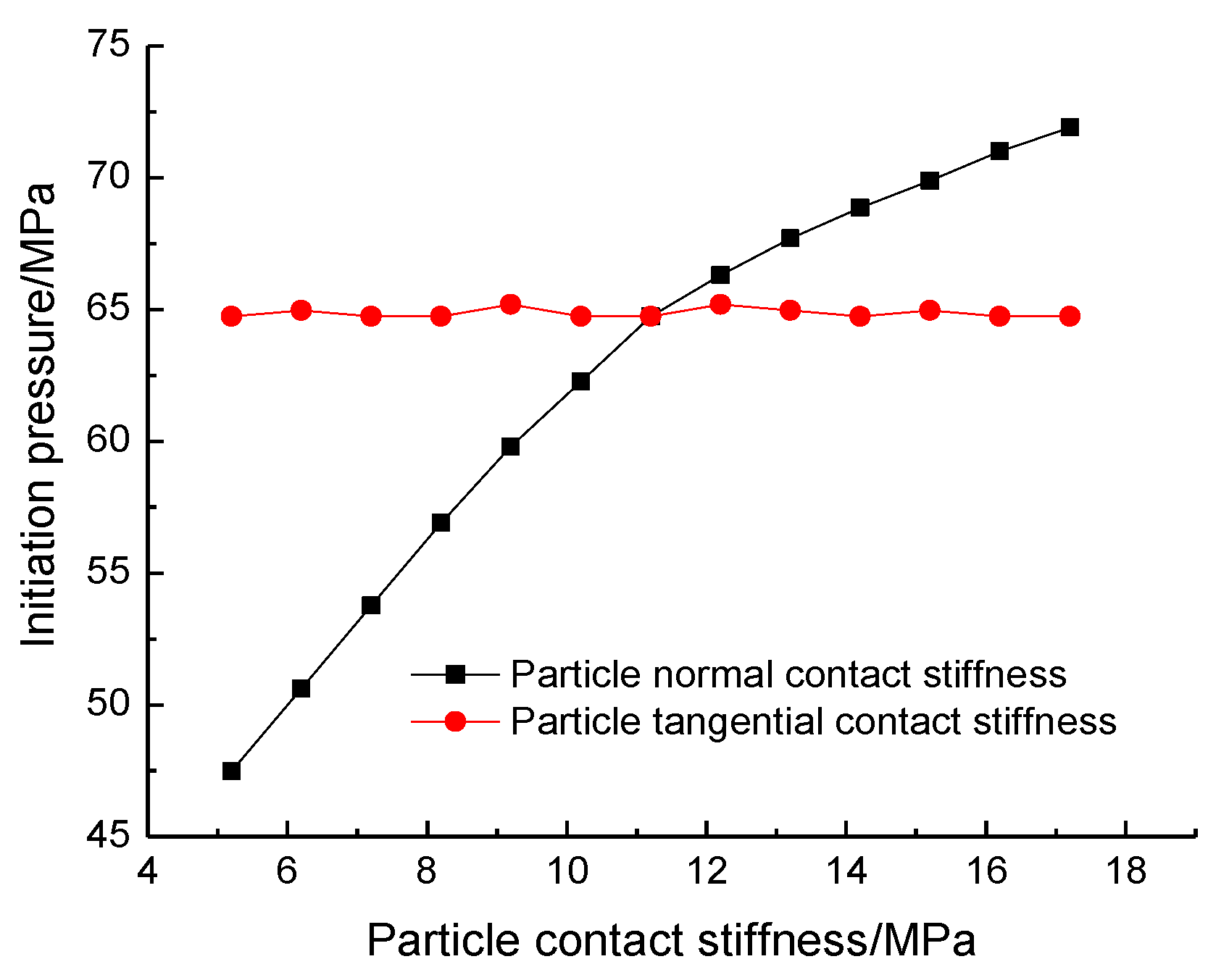
Under the injection pressure of 65 MPa, we simulated the influence of particle normal contact stiffness (kn) and tangential contact stiffness (ks) on the fracturing effect is 5.2 GPa~17.2 GPa, each time increasing by 1 GPa;
(4)
Under the optimal injection pressure, we simulated the influence of the normal connection strength and the tangential joint strength on the fracturing effect is 27.5 MPa~52.5 MPa, each time increasing by 2.5 MPa.

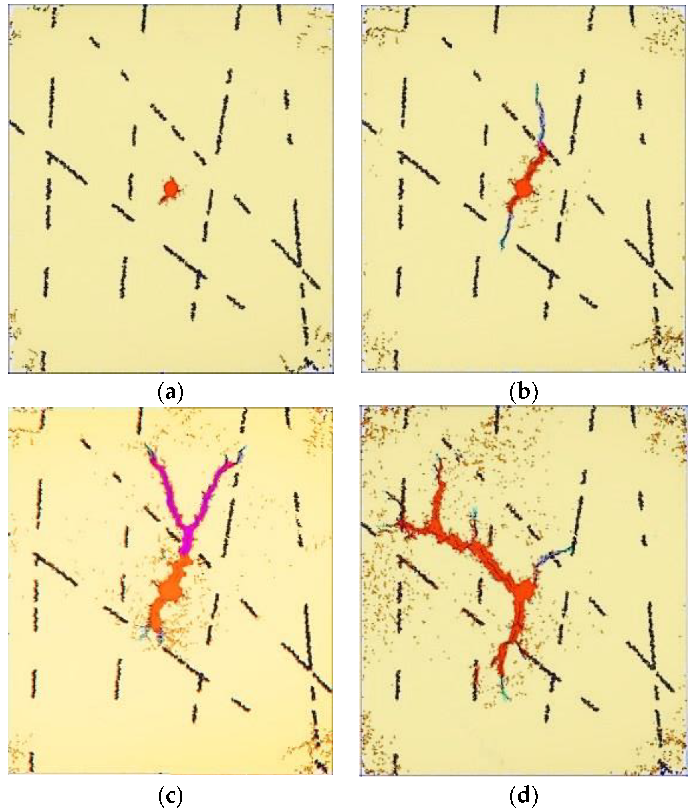
4.3.1. Analysis of Injection Pressure Influence on Reservoir Fracturing

The injection pressure was changed while other factors were unchanged, and the influence of the parameter variation on the maximum slit length and slit width was investigated. The relationship between the number of micro-fractures and the sub-steps under different injection pressure conditions is shown in Figure 5.
It can be seen from Figure 5 that when the injection pressure P0 < 35 MPa, the tensile stress existing between the reservoir particles is smaller than the joint strength of the particles, so the fracture layer is not generated in the reservoir, and the number of micro-fractures is always 0. When the injection pressure is increased to 35 MPa, the tensile stress between the particles exceeds the joint strength of the particles, the joint between the particles is broken, and a fracture is generated corresponding to the fracture of each joint, and the injection pressure at this time is the initiation pressure. When the injection pressure P0 is in the range of 35 MPa~55 MPa, the number of micro-fractures increases slowly with time, and tends to a stable value after a certain time sub-step. At this time, a plurality of short fractures penetrate each other to form a major fracture; when the injection pressure P0 > 55 MPa, the number of fractures reaches a maximum value in a very short time and is maintained at this value. Excessive injection pressure causes the reservoir to produce multiple fractures in other directions in addition to the major fracture, which can easily cause fragmentation damage to the reservoir (see Figure 5).
In the PFC model, the fracture of each parallel connection is necessarily accompanied by the formation of a new fracture. Figure 6 shows the relative relationship between the parallel joint fracture and the fracture generation, in which the colored short line indicates the joint fracture and the new fracture-formation region.

4.3.2. Fluctuation Analysis of Initiation Pressure on Reservoir Fracturing

Fluctuation Analysis of Initiation Pressure Caused by the Horizontal Principal Stress

Figure 7 shows the Fluctuation of initiation pressure caused by the minimum and maximum horizontal principal stresses.
From Figure 7, it can be seen that the key control-principal stress of fracture-initiation is the horizontal minimum principal stress. The increase of the minimum principal stress makes the fracture-initiation pressure of the wellbore increase, and the increasing change is almost linear. However, the increase of the horizontal maximum principal stress has little effect on the fracture initiation pressure. Thus, it is confirmed that the formation fracture is along the direction of the maximum principal stress.

Fluctuation Analysis of Initiation Pressure Caused by Particle Contact Stiffness

Figure 8 shows the Fluctuation of initiation pressure caused by particle-normal and tangential-contact stiffness.
From Figure 8, it can be seen that the fracture initiation in hydraulic fracturing is mainly caused by tensile failure. Near the wellbore, the increase of wellbore pressure first causes the hoop stress around the wellbore to reach the failure extreme, thus the fractures form a radial-spread distribution.

Fluctuation Analysis of Initiation Pressure Caused by Particle Connection Strength

Figure 9 shows the Fluctuation of initiation pressure caused by particle normal and tangential connection strength.
It can be seen from Figure 9 that the relationship between the fracture initiation pressure and the normal connection strength and the tangential connection strength shows a linear growth trend. From the slope of the two curves, the influence of normal connection strength on the initiation pressure is greater than that of tangential connection strength.

5. Analysis of Fracturing Influence Factors Considering Temperature Effect

The HDR reservoir rocks are mostly granite. A large number of studies show that the mechanical properties of granite change with the change in temperature [32,33,34]. In this section, by setting the micro parameters of rocks at 250 °C, 300 °C, 350 °C, and 400 °C (Table 3), we studied the influence of injection pressure, horizontal minimum principal stress, and permeability on reservoir fracturing.

5.1. Analysis of HDR Low Reservoir Fracturing Influenced by Injection Pressure

We kept other conditions unchanged and studied the relationship between injection pressure and fracturing. Figure 10 shows the relationship between the maximum length and width of hydraulic fracture and injection pressure.
It can be seen from Figure 5 that with the increase of injection pressure, the length and width of fractures first increase and then decrease after a period of growth. We analyzed the reason for the decrease and found that when the injection pressure increases, multiple groups of fractures appear around the wellbore, and form a radial spread distribution, which shares the energy of fluid pressure, so the maximum fracture width and length show a trend of decrease.
We assume that the optimal injection pressure is the injection pressure that produces the maximum fracture volume (the value equals the maximum fracture multiplied by the maximum fracture width). Because of the difference in formation temperature, the mechanical property of the rock will decrease with increasing reservoir temperature, so that the optimal injection pressure for the maximum fracture volume will be reduced. From Figure 10, the optimal injection pressure will be 60 MPa at 250 °C, while the optimal injection pressure reduces to 40 MPa at 400 °C. In addition, when the injection pressure increases to a certain point, the maximum width of the fracture presents a slow upward trend. It can be seen that the increase of injection pressure will increase the number of fractures on the wellbore, but at a certain point the number of fractures will not increase any more, and the new energy will make the main fracture widen. At the same time, the secondary fracture will maybe occur to share the new energy.

5.2. Analysis of HDR Low Reservoir Fracturing Influenced by Horizontal Minimum Principal Stress

We kept other conditions unchanged and studied the relationship between horizontal minimum-principal stress and fracturing. Figure 11 shows the relationships among the maximum-lengths and -widths of hydraulic fracture and the horizontal minimum principal stress.
It can be seen from Figure 5 that the influence of the minimum horizontal principal stress on the maximum fracture length and on the fracture width is very obvious, and that the maximum fracture length and fracture width decrease linearly with the increase of σh. Also, during the change of the minimum horizontal principal stress, there is a sudden change in the maximum fracture length and the fracture width. We think the reason is that the fracture fluid at this stage changes from diversion to permeability.
We set the minimum principal stress corresponding to curve jump as the key minimum principal stress. And we find that the key minimum principal stress decreases with increasing reservoir temperature. The key minimum principal stress is 51 MPa at 250 °C, while the key minimum principal stress decreases to 49 MPa at 400 °C.
The influence of the minimum horizontal principal stress on the maximum fracture length and the fracture width can be divided into three stages:
(1)
When σh is less than the key minimum principal stress, the maximum fracture length and the fracture width decrease linearly with the increase of the minimum horizontal principal stress;
(2)
When σh crosses the key minimum principal stress, the maximum fracture length and the fracture width sharply reduced;
(3)
When σh is bigger than the key minimum principal stress, the relationship between the maximum fracture length and the fracture width and the minimum principal stress is approximately linearly inversely proportional, and the slope is smaller than that in the first stage.

5.3. Analysis of HDR Low Reservoir Fracturing Influenced by Reservoir Permeability

We kept other conditions unchanged and studied the relationship between HDR reservoir permeability and fracturing. Figure 12 shows the relationship between the maximum length and width of hydraulic fracture and HDR reservoir permeability.
It can be seen from Figure 12 that the width and length of hydraulic fracture increase with the increase of formation permeability. When the permeability is small, the increase rate of fracture width and length is small. When the permeability exceeds a certain value, the increased rate of fracture width and length is large. It can be seen from Figure 11 that the inflection point value of the two changes is about 5.8 md. By analyzing the causes of these two changes, we think that the former change in the width and length of hydraulic fracture mainly depends on the fracture pressure. The latter change in the width and length of hydraulic fracture is the result of the joint action of reservoir seepage and fracture pressure. These can quickly reduce the effective stress of HDR low permeability rock skeletons, making the formation fracturing easier, so the length and width of the fractures increase rapidly.
It can also be seen from Figure 12 that with the increase in temperature, the increase of fracture length and width gradually increases, which is related to the decrease of rock mechanical parameters with the increase in temperature.

6. Discussion

This paper presents a new fluid-solid coupling model in the HDR reservoir, which divides the reservoir into two parts: rock and fracture [see Equations (1)–(5)] according to the seepage-field equation and displacement-field equations. Then a particle-flow numerical model is established by considering the fluid-region effort and particle movement. We defined the hydraulic fracturing micro-fracture based on the particle-contact connection model (Section 3).
According to the above model, this paper establishes a numerical analysis case (see Figure 3), gains the fracture propagation-process image (Figure 4), and analyzes the injection-pressure influence on reservoir fracturing and fluctuation analysis of initiation pressure caused by the horizontal principal stress, particle contact stiffness, and particle connection strength (Figure 6, Figure 7 and Figure 8). It is found that the fracture-initiation pressure is proportional to the magnitude of minimum horizontal stress, particle normal contact stiffness, particle normal and tangential connection strengths, and that the injection pressure value is the key factor in whether the fracture propagation can quickly enter the stable state.
At last, this paper considers the temperature of the HDR reservoir. The temperature will reduce the permeability and porosity of rocks, because the thermal expansion of rock matrix materials will reduce the pore throat and effective volume in the matrix, thus reducing the permeability and porosity. However, this paper simply reflects the temperature effect on the difference of micro-parameters of HDR rock particles (Table 3) and analyzes the influence of injection pressure, horizontal minimum principal stress, and reservoir permeability on the change of fracturing.
In addition, we only consider the change of temperature field caused by injected fracturing fluid and thermal rupture caused by the change of temperature. Thus an improved and more general approach by considering temperature, plus fluid and mechanical coupling (HTM), should be proposed in future work to completely resolve the issue.

7. Conclusions

To study the hydraulic-fracturing mechanism from a mesoscopic perspective, a particle-flow analytical model of hydraulic fracturing of HDR low permeability reservoirs considering fluid-solid coupling is established. We discuss the coupled environment of reservoir particles and fracturing fluid, the effects of parameters such as injection pressure, horizontal principal stress, particle contact stiffness, and particle joint strength on the reservoir fracturing effect. We found that with the minimum horizontal principal stress, particle normal-contact stiffness, particle normal and tangential joint strength, and the fracturing pressure increase linearly. At last, the temperature of HDR reservoir is considered by setting the difference of micro-parameters of HDR rock particles. We found that fracture length and width show a trend of increase before decrease with the increase of injection pressure, an inverse relationship with minimum horizontal principal stress, and a positive relationship with HDR reservoir permeability.

Author Contributions

Methodology, H.F.; Formal analysis, S.Y.; Data curation, P.L. and Y.Z.; Writing—original draft, X.Z.; Writing—review & editing, H.F. All authors have read and agreed to the published version of the manuscript.

Funding

This research was funded by Supported by the National Key Research and Development Program of China (2019YFF0217504).

Data Availability Statement

Not applicable.

Conflicts of Interest

The authors declare no conflict of interest.

References

  1. Jing, T.; Zhao, W.T.; Gao, S.; Wang, J.; Zhang, J. Practice and Technical Feasibility Study of Hot Dry Rock Geothermal Development. Sino-Glob. Energy 2018, 23, 17–21. [Google Scholar]
  2. Moya, D.; Aldas, C.; Kaparaju, P. Geothermal energy: Power plant technology and direct heat applications. Renew. Sustain. Renew. Energy 2018, 94, 889–901. [Google Scholar] [CrossRef]
  3. Xu, T.; Hu, Z.; Li, S.; Jiang, Z.; Hou, Z.; Li, F.; Liang, X.; Feng, B. Enhanced geothermal system: International progresses and research status of China. Acta Geol. Sin. 2018, 92, 1936–1947. [Google Scholar]
  4. Liu, H.; Li, J.; Pang, H.; Zheng, H.; Liu, D.; Sun, X.; Song, W. Study on ultra-temperature cement slurry technology for hot dry rock well GR1 in Qinghai Gonghe basin. Drill. Fluid Complet. Fluid 2020, 37, 202–208. [Google Scholar]
  5. Zhou, Z.; Jin, Y.; Lu, Y.; Zhou, B. Present challenge and prospects of drilling and hydraulic fracturing technology for hot dry rock geothermal reservoir. Sci. Sin. Phys. Mech. Astron. 2018, 48, 124621. [Google Scholar] [CrossRef] [Green Version]
  6. Zhou, Z.; Jin, Y.; Zeng, Y.; Zhang, X.; Zhou, J.; Zhuang, L.; Xin, S. Investigation on fracture creation in hot dry rock geothermal formations of China during hydraulic fracturing. Renew. Energy 2020, 153, 301–313. [Google Scholar] [CrossRef]
  7. Wu, F.; Li, D.; Fan, X.; Liu, J.; Li, X. Analytical interpretation of hydraulic fracturing initiation pressure and breakdown pressure. J. Nat. Gas Sci. Eng. 2020, 76, 103185. [Google Scholar] [CrossRef]
  8. Li, G. Research on Reservoir Property and Permeability under Hydraulic Fracturing in Hot Dry Rock. Master′s Thesis, Taiyuan University of Technology, Taiyuan, China, 2018. [Google Scholar]
  9. Xu, J.; Wu, K.; Yang, S.; Cao, J.; Chen, Z. Nanoscale free gas transport in shale rocks: A hard-sphere based model. In Proceedings of the SPE Unconventional Resources Conference, Calgary, AB, Canada, 16 February 2017. [Google Scholar]
  10. Xu, J.; Chen, Z.; Wu, K.; Li, R.; Liu, X.; Zhan, J. On the flow regime model for fast estimation of tight sandstone gas apparent permeability in high-pressure reservoirs. Energy Sources Part A Recovery Util. Environ. Eff. 2019, 10, 1–12. [Google Scholar] [CrossRef]
  11. Hagoort, J.; Weatherill, B.D.; Settari, A. Modeling the Propagation of Waterflood-Induced Hydraulic Fractures. Soc. Pet. Eng. J. 1980, 20, 293–303. [Google Scholar] [CrossRef]
  12. Settari, A.; Cleary, M.P. Development and testing of a pseudo-three-dimensional model of hydraulic fracture geometry. SPE 1982, 01, 10505. [Google Scholar] [CrossRef]
  13. Rahim, Z.; Holditch, S.A. Using a three-dimensional concept in a two-dimensional model to predict accurate hydraulic fracture dimensions. J. Pet. Sci. Eng. 1995, 13, 15–27. [Google Scholar] [CrossRef]
  14. Zillur, R.; Holditch, S.A. The effects of mechanical properties and selection of completion interval upon the created and propped fracture dimension in layered reservoirs. J. Pet. Sci. Eng. 1995, 13, 29–45. [Google Scholar]
  15. Wei, Y.; Economides, M.J. Transverse hydraulic fractures from a horizontal well. In Proceedings of the SPE Annual Technical conference and Exhibition, Dallas, TX, USA, 9–12 October 2005. [Google Scholar]
  16. Cheng, Y.; Wang, G.; Wang, R. Rock mechanics problems in horizontal well fracturing. Chin. J. Rock Mech. Eng. 2004, 23, 2463–2466. [Google Scholar]
  17. Zhang, G.; Chen, M. Non-planar propagation of hydraulic fracture around horizontal well-bole. Eng. Mech. 2006, 23, 160–165. [Google Scholar]
  18. Zhang, G.; Liu, H.; Zhang, J.; Wu, H.; Wang, X. Three-dimensional finite element numerical simulation of horizontal well hydraulic fracturing. Eng. Mech. 2011, 28, 101–106. [Google Scholar]
  19. Zhang, G.; Liu, H.; Zhang, J. Simulation of hydraulic fracturing of oil well based on fluid-solid coupling equation and non-linear finite element. Acta Pet. Sin. 2009, 30, 113–116. [Google Scholar]
  20. Bian, K.; Chen, Y.; Liu, J.; Cui, D.; Li, Y.; Liang, W.; Han, X. The unloading failure characteristics of shale under different water absorption time using the PFC numerical method. Rock Soil Mech. 2019, 41, 1–13. [Google Scholar]
  21. Cong, Y.; Cong, Y.; Zhang, L.; Jia, L.; Wang, Z. 3D particle flow simulation of loading-unloading failure process of marble. Rock Soil Mech. 2019, 40, 1179–1186. [Google Scholar]
  22. Tsuji, Y.; Kawaguchi, T.; Tanaka, T. Discrete particle simulation of two-dimension al fluidized bed. Powder Technol. 1993, 77, 79–87. [Google Scholar] [CrossRef]
  23. Potapov, A.; Hunt, M.; Campbell, C. Liquid solid flows using smoothed particle hydrodynamics and the discrete element method. Powder Technol. 2001, 116, 204–213. [Google Scholar] [CrossRef]
  24. Jackson, R. Locally averaged equations of motion for a mixture of identical spherical particles and a Newtonian fluid. Chem. Eng. Sci. 1997, 52, 2457–2469. [Google Scholar] [CrossRef]
  25. Sun, F.; Zhang, D.; Chen, T. Meso-mechanical simulation of fracture grouting in soil. Chin. J. Geotech. Eng. 2010, 32, 474–480. [Google Scholar]
  26. Yang, F. Stability Analysis of Sandy Soil Tunnel End Based on PFC Fluid Structure Coupling. Master′s Thesis, Changsha University of Technology, Changsha, China, 2018. [Google Scholar]
  27. Zhang, W.; Sun, J.; Qu, Z.; Guo, T.; Gong, F.; Zhang, H. Thermo-hydro-mechanical coupling model and comprehensive evaluation method of high temperature geothermal extraction. Prog. Geophys. 2019, 34, 668–675. [Google Scholar]
  28. Guo, L.; Zhang, Y.; Hu, Z.; Xun, T.; Lan, C.; Su, J. The research of hydraulic fracturing and development strategy in enhanced geothermal system. J. Eng. Geol. 2015, 23, 235–241. [Google Scholar]
  29. Sun, Z.; Xu, Y.; Lu, S.; Xu, Y.; Sun, Q.; Cai, M.; Yao, J. A thermo-hydro-mechanical coupling model for numerical simulation of enhanced geothermal systems. J. China Univ. Pet. 2016, 40, 109–117. [Google Scholar]
  30. Yang, Y.; Chang, X.; Zhou, W.; Zhou, C. Simulation of Hydraulic Fracturing of Fractured Rock Mass by PFC2D. J. Sichuan Univ. (Eng. Sci. Ed.) 2012, 44, 78–85. [Google Scholar]
  31. Potyond, D.O.; Cundall, P.A. A bonded particle model for rock. Int. J. Rock Mech. Min. Sci. 2004, 41, 1329–1364. [Google Scholar] [CrossRef]
  32. Xi, B.; Wu, Y.; Wang, S.; Xiong, G.; Zhao, Y. Experimental study on mechanical properties of granite taken from Gonghe basin, Qinghai province after high temperature thermal damage. Chin. J. Rock Mech. Eng. 2020, 1, 69–83. [Google Scholar]
  33. Zhu, Z.; Tian, H.; Dong, N.; Dou, B.; Chen, J.; Zhang, Y.; Wang, B. Experimental study of physico-mechanical properties of heat-treated granite by water cooling. Rock Soil Mech. 2018, 39, 169–176. [Google Scholar]
  34. Sun, Q.; Zhang, Z.; Xue, L.; Zhu, S. Physico-mechanical properties variation of rock with phase transformation under high temperature. Chin. J. Rock Mech. Eng. 2013, 32, 935–942. [Google Scholar]
Figure 1. Model of flow pipe and fluid region in DEM simulation.
Processes 11 00976 g001
Figure 2. Pressure distribution in the fluid region.
Processes 11 00976 g002
Figure 3. Particle flow numerical model of hydraulic fracturing. The yellow area represents the particles to be fractured; the black lines connecting the round particles represent the contact connection between the particles; the red region is the wellbore.
Processes 11 00976 g003
Figure 4. The fracture propagation shape of different time sub-steps for the injection pressure 45 MP. The yellow area represents the particles to be fractured; the black lines is the fracture; the blue lines connecting the round particles represent the contact connection between the particles; the red region is the wellbore. (a) Time substep = 100. (b) Time substep = 200. (c) Time substep = 300. (d) Time substep = 400. (e) Time substep = 500.
Processes 11 00976 g004
Figure 5. The number of micro-fractures with the time variation of the sub-step for the injection pressure.
Processes 11 00976 g005
Figure 6. The contact-bond fracture and micro-fracture generation for the different injection pressure. (a) P0 = 30 MPa. (b) P0 = 40 MPa. (c) P0 = 50 MPa. (d) P0 = 60 MPa.
Processes 11 00976 g006
Figure 7. The relation between initiation pressure and horizontal principal stress.
Processes 11 00976 g007
Figure 8. The relation between initiation pressure and particle-contact stiffness.
Processes 11 00976 g008
Figure 9. The relation between initiation pressure and particle connection strength.
Processes 11 00976 g009
Figure 10. The relation between fracture length and width and injection pressure. (a) Fracture length curves. (b) Fracture width curves.
Processes 11 00976 g010
Figure 11. The relation between fracture length and width and horizontal minimum principal stress. (a) Fracture length curves. (b) Fracture width curves.
Processes 11 00976 g011
Figure 12. The relation between fracture length and width and HDR reservoir permeability. (a) Fracture length curves. (b) Fracture width curves.
Processes 11 00976 g012
Table 1. Reservoir particles micromechanics parameters.
Rmax/mRmax
/Rmin
Interparticle Friction CoefficientPorosityParticle Normal Contact Stiffness kn/(N·m−1)Particle Tangential Contact Stiffness ks/(N·m−1)Particle Normal Connection Strength/MPaShear Strength of Particles/MPaDensity/
Kg·m−3
0.042.700.220.1511.20 × 10911.20 × 10942.542.52320
Table 2. The basic parameters of the fluid domain.
Formation Pressure
/MPa
The Apparent Volume of a Domain
Vd/mm3
Permeability
/mD
Coefficient of Viscosity
/Pa·s
Number of Pipes in a Domain NConductivity Coefficient
K/(m·s−1)
Volume Modulus of Fluid
Kd/kPa
Piping Diameter
a/mm
2515.60.321 × 10−81.0 × 1061
Table 3. Reservoir particles micromechanics parameters at different temperatures.
Temperature/
°C
Interparticle Friction CoefficientPorosityParticle Normal Contact Stiffness kn/(N·m−1)Particle Tangential Contact Stiffness ks/(N·m−1)
2500.220.1511.20 × 10911.20 × 109
3000.220.158.98 × 1098.98 × 109
3500.230.147.21 × 1097.21 × 109
4000.230.145.78 × 1095.78 × 109
Disclaimer/Publisher’s Note: The statements, opinions and data contained in all publications are solely those of the individual author(s) and contributor(s) and not of MDPI and/or the editor(s). MDPI and/or the editor(s) disclaim responsibility for any injury to people or property resulting from any ideas, methods, instructions or products referred to in the content.

