Review

Recent Developments of Light-Harvesting Excitation, Macroscope Transfer and Multi-Stage Utilization of Photogenerated Electrons in Rotating Disk Photocatalytic Reactor

School of Environmental Science and Engineering, Shanghai Jiao Tong University, No. 800, Dongchuan Road, Shanghai 200240, China
*
Authors to whom correspondence should be addressed.
Processes 2023, 11(3), 838; https://doi.org/10.3390/pr11030838
Submission received: 13 February 2023 / Revised: 6 March 2023 / Accepted: 9 March 2023 / Published: 10 March 2023
(This article belongs to the Special Issue State of the Art of Waste Utilization and Resource Recovery)

Abstract

:
The rotating disk photocatalytic reactor is a kind of photocatalytic wastewater treatment technique with a high application potential, but the light energy utilization rate and photo quantum efficiency still need to be improved. Taking photogenerated electrons as the starting point, the following contents are reviewed in this work: (1) Light-harvesting excitation of photogenerated electrons. Based on the rotating disk thin solution film photocatalytic reactor, the photoanodes with light capture structures are reviewed from the macro perspective, and the research progress of light capture structure catalysts based on BiOCl is also reviewed from the micro perspective. (2) Macroscope transfer of photogenerated electrons. The research progress of photo fuel cell based on rotating disk reactors is reviewed. The system can effectively convert the chemical energy in organic pollutants into electrical energy through the macroscopic transfer of photogenerated electrons. (3) Multi-level utilization of photogenerated electrons. The photogenerated electrons transferred to the cathode can also generate H2O2 with oxygen or H2 with H+, and the reduction products can also be further utilized to deeply mineralize organic pollutants or reduce the nitrate in water. This short review will provide theoretical guidance for the further application of photocatalytic techniques in wastewater treatment.

1. Introduction

Photocatalytic (PC) technology has attracted long-term and extensive attention from researchers all over the world because of its attractive prospect of utilizing solar energy in deep oxidation [1]. Based on the photocatalytic mechanism [2,3], some semiconductors are used to convert solar energy into electrical or chemical energy [4,5], and then oxidize or reduce the substrate to obtain useful products (such as hydrocarbons) or energy (such as H2 and electrical energy) [6,7,8]. By adding photocatalysts into roads or building materials, volatile organic compounds (VOCs) released from automobiles, fuel combustion, building materials, and consumer products can be effectively captured, and these pollutants can be degraded by ultraviolet light or sunlight [9,10]. As the photocatalyst material has super hydrophobicity when exposed to light, the residual pollutants and dust on its surface can also be cleaned under the action of rain to keep the building surface clean and beautiful [11,12]. At the same time, photocatalysis can also effectively kill bacteria, and so it is widely used in medical devices, antibacterial materials, and food preservation [13,14].
Photocatalysis has the advantages of a strong oxidation ability, no chemical addition, and no selectivity to substrate, which results in a large number of research papers on the photocatalytic treatment of water pollutants being published every year [15,16]. The treatment object also involves a variety of pollutants that are difficult to biodegrade, such as dyes [17], phenolic compounds [18], pesticides, and herbicides [19,20]. However, as photocatalysis technology still has some problems in water treatment, such as low light energy utilization rate, low light quantum efficiency, and low reaction efficiency, which are difficult to solve, it cannot be effectively applied on a large scale, and only small engineering equipment is available.
Chong et al. summarized a number of key scientific and technological requirements in the process of efficient photocatalytic water treatment [21], including (i) the development of photocatalysts with wider spectral range, (ii) the development of catalyst-loading technology to reduce the cost of catalyst and solution separation, (iii) the broadening of the scope of photocatalysis application conditions, including a wider pH application range and a lesser dissolved oxygen demand, (iv) the combination with other water treatment technologies to improve the reaction rate and mineralization efficiency, (v) and a more efficient photocatalytic reactor design. Different from ordinary solution chemical reaction, in addition to temperature, concentration, dissolved oxygen, pH, and other factors, it is also necessary to consider the light energy utilization rate and photo quantum efficiency in the process of photocatalytic water treatment. These two factors greatly affect the reaction efficiency of photocatalytic water treatment, thus limiting its industrial application.
The light energy utilization rate refers to the ratio of the light energy absorbed by the catalyst to the light energy emitted by the light source. There is often a certain degree of light energy loss, which will affect the utilization of light energy and reduce the efficiency of photocatalysis. However, this point is often ignored by researchers, and there is no review or research paper to systematically analyze the path of light energy loss in the process of photocatalytic water treatment. As shown in Figure 1a, the main loss of light energy in the process of photocatalytic water treatment can be summarized as the absorption and reflection of light energy by the solution. According to Lambert Beer’s law, the absorbance of the solution is proportional to the thickness and concentration of the solution. The solution and pollutants in the solution will have strong absorption to the incident light, especially for the solution with a high chromaticity and long optical path. If a large amount of incident light is absorbed by the solution, only a small amount of light will illuminate the surface of the photocatalyst to excite the catalyst and complete the photocatalytic reaction, which will reduce the utilization rate of the light energy. Moreover, when the light irradiates on the catalyst surface, part of the light will be absorbed by the catalyst, while the other part will reflect on the surface (RCS). This kind of reflection also occurs on the solution surface (RSS). This reflection is particularly obvious for short-wavelength light, such as ultraviolet light, while most photocatalysts with a strong oxidation ability can only be excited by ultraviolet light, such as TiO2 and BiOCl.
In addition to the light energy utilization rate, the photo quantum efficiency is also very important for the photocatalytic reaction. According to the principle of photocatalysis shown in Figure 1b, the combination of photogenerated electrons and holes will greatly affect the photocatalysis efficiency, and the light quantum efficiency refers to the ratio of the light energy used for photocatalysis to the light energy absorbed by the catalyst. As for the commonly used anatase TiO2, although the photogenerated electrons and holes have extremely strong oxidation–reduction ability, the time of their combination is 10−9 s (ns), and the time range of the reaction between anatase TiO2 and the pollutants or H2O molecules adsorbed on its surface is 10−8~10−3 s. This difference in time results in the low photo quantum efficiency of TiO2, which also affects its photocatalytic reaction efficiency.
In order to further improve the utilization of light energy, researchers have conducted a lot of work in the recent years. As shown in Figure 2a, in terms of reducing the absorption of light energy by the solution, the design of a new type of solution film reactor can effectively shorten the optical path and reduce the absorption of incident light energy by the solution [22,23]. In terms of the macrostructure, changing the traditional planar photocatalytic substrate into a light capture structure, such as a wedge or pyramid structure, can make the light reflect multiple times inside the substrate, thus making full use of the reflected light on the surface of the catalyst and the solution (Figure 2b) [24,25]. In terms of the microscopic morphology of photocatalysts, the solid spherical structure of traditional photocatalysts can be changed to have a light capture structure, such as flower-like, hollow spherical, or yolk-shell structure [26,27,28,29,30], which can effectively utilize the reflected light on the surface of the catalyst, thus improving the utilization of the light energy.
The morphology, size, and crystal form of the catalyst will affect its photo quantum efficiency in varying degrees. At the same time, as shown in Figure 2c, by combining the catalyst with other materials, such as precious metals [31,32], semiconductors [33,34], and carbon materials [35,36], the heterojunction (Schottky junction or p-n junction) formed between different materials can be used to promote the transfer of photogenerated electrons, effectively separate photogenerated electrons and holes, and improve the efficiency of the photo quantum. In addition, the photocathode can also be applied to form a photochemical cell, and the photogenerated electrons can be transferred to the cathode under the action of an external electric field by applying a bias voltage to form a photoelectrocatalytic (PEC) system to realize the effective separation of photogenerated electrons and holes [37,38,39,40]. On this basis, select the appropriate cathode material and cathode system, and use the potential difference generated by the cathode and the photoanode to make the electrons spontaneously transfer to the cathode through the external circuit without external bias. In this process, not only can the pollutants be degraded on the surface of the photoanode, but also the photogenerated electrons that migrate to the cathode can be reasonably utilized to generate H2 or electric energy. As shown in Figure 2d, the catalyst oxidizes pollutants to produce H+ under the condition of illumination. In the absence of O2, H+ can be reduced by photogenerated electrons transferred to the cathode on the cathode surface, thus producing H2. In the presence of O2 in the solution, the photogenerated electrons transferred to the cathode will react with O2 to generate H2O or H2O2. This system is similar to the microbial fuel cell, which generates electric energy while degrading mineralized pollutants and realizes the low-temperature combustion of pollutants. Therefore, researchers call it photo fuel cell (PFC) [41,42,43,44,45]. PFC can not only effectively inhibit the recombination of photogenerated electrons and holes and improve the efficiency of photons, but it can also convert the chemical energy in pollutants into electrical energy, which has received more and more attention in recent years.
Focusing on the thin solution film photocatalytic reactor, the recent developments of photogenerated electrons’ highly efficient excitation, transfer, and utilization are summarized in this review. This review will provide a theoretical reference for photocatalytic treatment and the resource utilization of wastewater.

2. Photocatalytic Reactor Design to Improve Light Energy Utilization

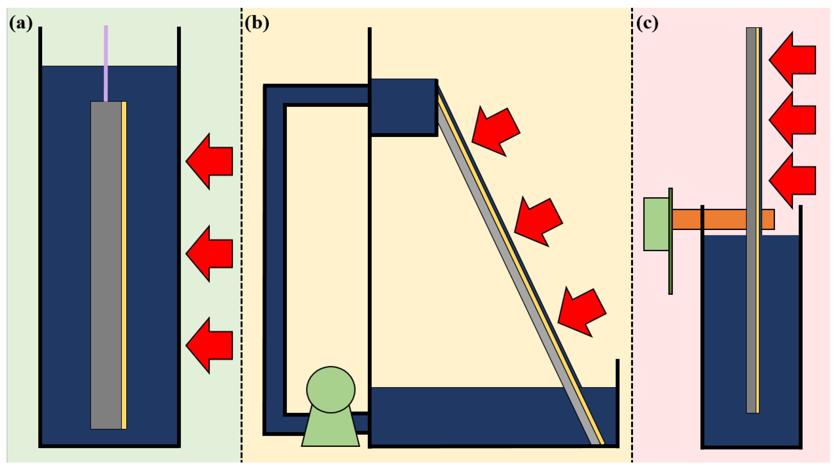
2.1. Thin Solution Film Photocatalytic Reactor

The design of the photocatalytic reactor is also very important for the utilization of light energy and the practical application of photocatalytic technology. Because the incident light will be absorbed by the solution, the solution film reactor has been proven as a reactor with a high light energy utilization. Compared with the suspension reactor and immersion reactor (Figure 3a), the incident light can reach the catalyst surface only through a thin solution film, which greatly reduces the absorption of light energy by the solution. Stephan et al. summarized three major advantages of the thin film photocatalytic reactor [46], including (1) its large irradiated area per unit volume, (2) the fact that the solution film only absorbs a small part of the incident light, (3) and its high surface area, which can enhance the mass transfer of O2.
According to different methods of forming the solution film, the thin film reactor mainly includes an inclined plate reactor (Figure 3b) and a rotating disk reactor (Figure 3c). The former one relies on gravity to form a solution film, while the latter one relies on centrifugal force. The solution needs to be lifted to the top of the reactor by the water pump in the inclined plate reactor, and then it flows down the inclined plate coated with the catalyst under the action of gravity. In this process, the solution flow rate will greatly affect the thickness of the solution film formation and the mass transfer of the system. A bias voltage-assisted inclined plate reactor was built by Xu et al. and exhibited a much higher removal rate of Rhodamine B (RhB) with a high concentration in comparison with a traditional immersed reactor [47,48,49]. Adams et al. also built a zigzag multi-stage inclined plate photocatalytic reactor to remove hydrocarbons in water [50]. At the same time, using the steps instead of the inclined plate can effectively prolong the water retention time and improve the photocatalytic degradation efficiency. Stephan et al. developed a stepped photocatalytic solution film reactor to treat pesticides in water, and established a model to analyze its treatment efficiency [46]. The difference between the calculated value of the model and the experimental value is less than 10%. At the same time, the model can also be applied to the analysis of photocatalytic degradation of other pollutants, and can predict the photocatalytic degradation rate without knowing the complete photocatalytic degradation pathway.

2.2. Rotating Disk Thin Solution Film Photocatalytic Reactor

The rotating disk reactor first developed by Dionysiou et al. is another representative thin solution film photocatalytic reactor [51,52,53,54]. The lower part of the disk is immersed in the solution, and the upper part is exposed to the air. A thin solution film can be formed on the surface of the disk through the rotation, and the incident light can directly irradiate on the catalyst surface through the thin film, thus reducing the absorption of the solution to the incident light [55]. Zhou et al. [56] and Huo et al. [57] used a TiO2 nanotube disk and flower-like TiO2 disk to replace the smooth structure TiO2 disk, respectively, and achieved a better photocatalytic effect. It was found that the rotating speed of the disk and the roughness of the surface of the disk affected the photocatalytic effect. The rotating speed affected the thickness and mass transfer efficiency of the solution film, and then affected the degradation of the target pollutants and the formation of the intermediate and final products.
The rotating disk reactor can be effectively amplified by multiple groups of vertical assembly. However, the solution film exposed to the air is difficult to utilize in sunlight due to shielding each other, so, an artificial light source must be used. A horizontal rotating disk reactor can overcome this disadvantage. Patterson et al. treated methylene blue in a horizontal rotating disk reactor under ultraviolet light, and the reaction rate was twice that of the traditional immersed reactor [58,59]. In the horizontal rotating disk reactor, the solution is sprayed onto the horizontal disk through the central nozzle, and the solution film is formed through the rotation of the disk and finally flows down from the edge of the disk. Compared with the vertical disk reactor, although the horizontal disk reactor can utilize sunlight, it consumes more electric energy. At the same time, Patterson et al. also observed that under the conditions of high speed or a high flow rate, it is easy to form extremely uneven turbulence on the surface of the horizontal disk, which will affect the utilization of light energy and the photocatalytic effect [60]. Furthermore, the horizontal disk reactor occupies a large area and is not suitable for practical applications. Similar to the rotating disk reactor, the rotating drum reactor is easier to scale up, and has been a wide concern of researchers in recent years [61,62].
Yao et al. [63] prepared a TiO2 particle anode (Figure 4a) and TiO2 nanotube anode (Figure 4b) using the sol-gel and anodic oxidation method, respectively, and applied these two anodes in an immersed reactor, inclined plate solution film reactor, and rotating disk solution film reactor to study their photocatalytic degradation performances of RhB. The effect of stirring was investigated in the immersed reactor. The decolorization rate of RhB by the TiO2 nanotube anode was 1.5 times better than that of TiO2 particle anode in the absence of stirring. The TiO2 nanotube anode had larger surface area and stronger photocurrent response in comparison with the TiO2 particle anode, resulting in the better photocatalytic degradation performance of RhB. The decolorization rates obtained by the two anodes are basically the same under the stirring condition, indicating that the mass transfer of the target pollutant should be the main factor that limits the degradation performance in comparison with the activity of the electrode surface. In the inclined plate reactor, because the absorption of incident light by the solution was effectively avoided, the decolorization efficiencies of the two anodes were significantly better than those obtained in the immersed reactor. However, due to the great enhancement of mass transfer, there was no significant difference in the decolorization efficiency between the two anodes (Figure 4c). Because the TiO2 nanotube has a closed tubular structure and the diameter of the tube is very small (nanometer level), the tube is easily sealed by water, which makes it difficult for the air inside the tube to move, thus reducing the effective surface area of TiO2 nanotubes. At the same time, if the solution is flowing, it is also difficult for the solution in the tube to transfer to the outside. Centrifugal force generated by rotating the photoanode can effectively promote the mass transfer of solution in the nanotube. The RhB decolorization performance of the TiO2 nanotube anode is better than that of the TiO2 particle anode in the rotating disk reactor, and the gap between the two anodes becomes more and more obvious with the increase in the RhB concentration (Figure 4d). The solution film on the surface of the TiO2 nanotube is repeatedly exchanged in the air and solution through the rotation of the disk, and the solution in the tube is thrown out under the action of centrifugal force, which is conducive to the mass transfer of the solution in the nanotube, so that the advantage of the large surface area of the nanotube can be fully displayed (Figure 4e,f).

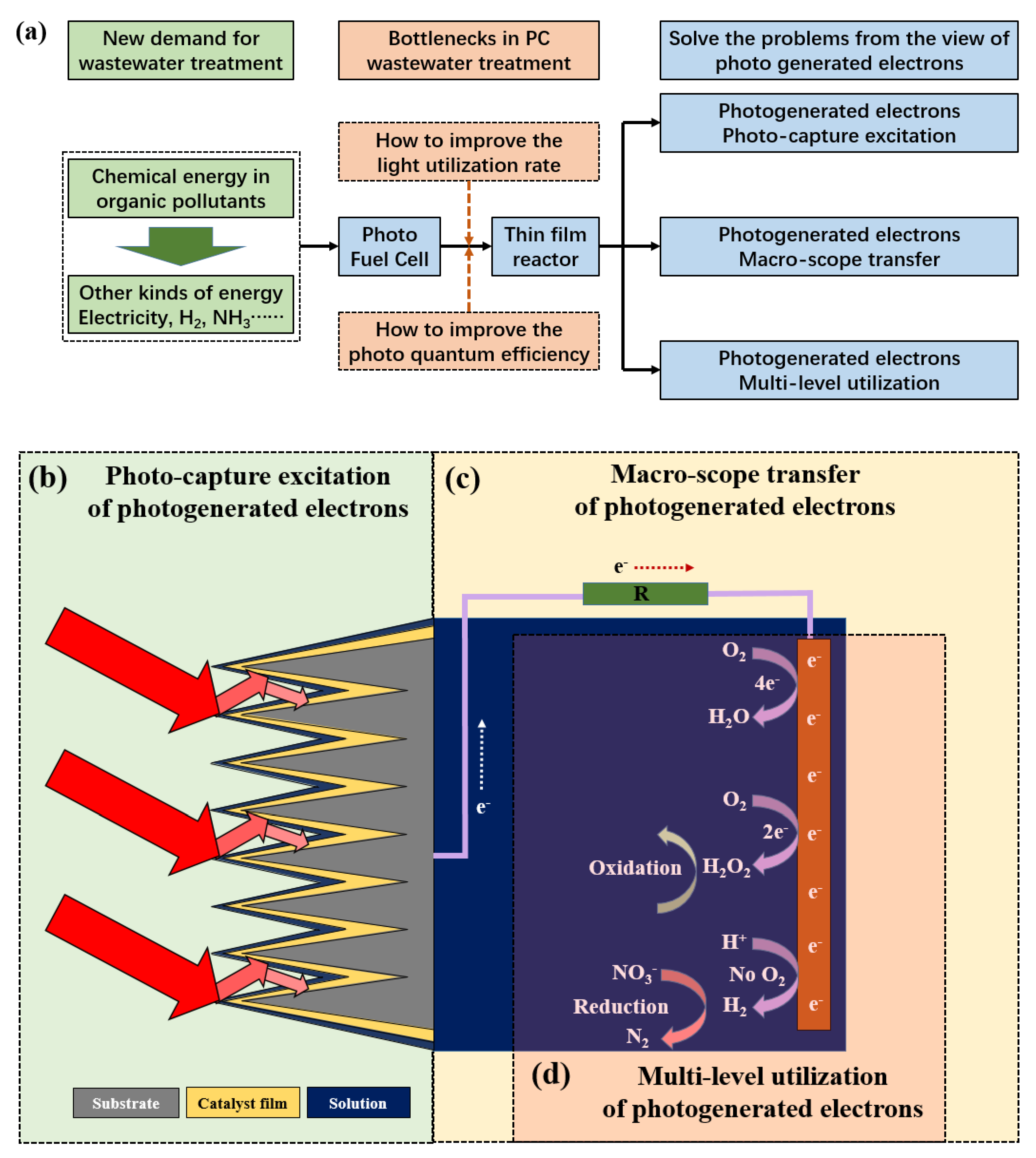
2.3. Research Fields of Further Improving the Efficiency of Rotating Disk Photocatalytic Reactor

According to the analysis of the bottlenecks of the photocatalytic water treatment, photogenerated electrons play a crucial role in the photocatalytic process. Although the solution film reactor can effectively solve the problem of absorption of incident light by the solution, the following issues still need to be further investigated from the perspective of the excitation and utilization of photogenerated electrons, especially in the thin solution film photocatalytic reactor such as the rotating disk reactor.
(1)
The light-harvesting excitation of photogenerated electrons. How to further improve the utilization rate of light energy, for example, efficiently capturing reflected light, so as to promote the advanced oxidation of organic pollutants.
(2)
The macroscopic transfer of photogenerated electrons. How to realize the conversion from chemical energy in organic pollutants to electrical energy through the macroscopic transfer of photogenerated electrons.
(3)
The multi-level utilization of photogenerated electrons. How to use the photogenerated electrons transferred to the cathode at multiple levels to realize the hydrogen production or simultaneous removal of other pollutants in the wastewater.

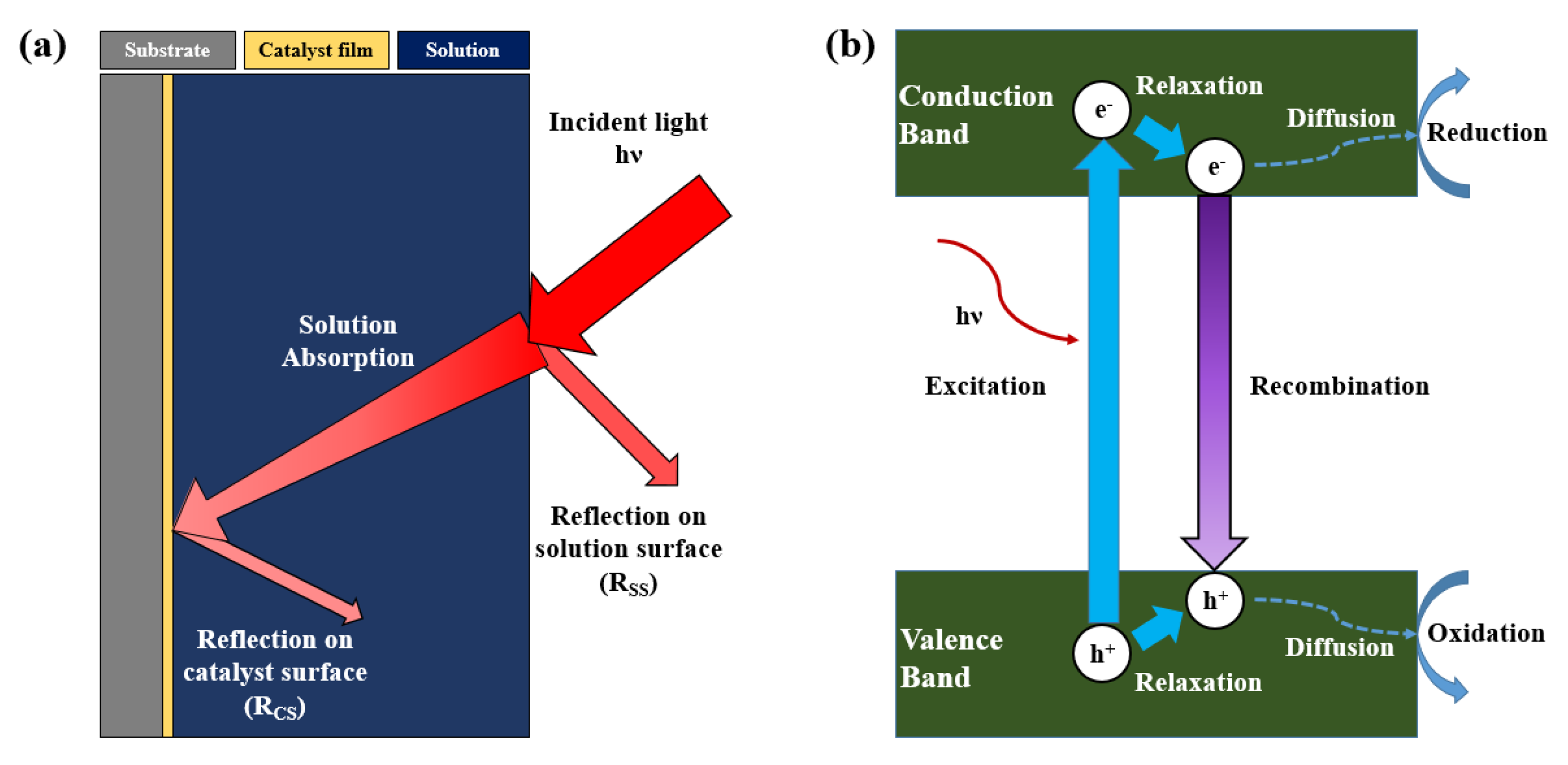
3. Light-Harvesting Excitation of Photogenerated Electrons

In addition to the absorption of incident light by the solution, there is often a certain degree of reflected light energy loss in the process of photocatalytic water treatment, including the reflection on the catalyst surface and the reflection on the solution surface. This loss of light energy is always ignored by researchers, but it greatly affects the utilization of light energy. Therefore, how to fundamentally improve the utilization of light energy and promote the oxidation of organic pollutants through the improvement of the macrostructure of the reactor, combined with the adjusting of the micro-structure of the catalyst, is an important bottleneck to limit the application of photocatalytic technology in water treatment.

3.1. Design of Light-Harvesting Structured Photoanodes

From a macro point of view, photoanodes with light capture structures, such as a wedge or a pyramid structure, have been developed by researchers and applied to a rotating disk thin film photocatalytic reactor. The thin solution film can effectively reduce the absorption of incident light using high-chroma wastewater, and the wedge or pyramid structure can not only increase the surface area of the photoanode, but can also capture the incident light [64,65]. Compared with the planar structured photoanode, it is found that the removal amount of pollutants per unit area of the light capture structured photoanode increases gradually with the increase in its initial concentration. By optimizing various experimental conditions, including the bottom-to-height ratio of the wedge or pyramid, it was found that when the initial concentration of RhB increased to 150 mg L−1, the removal amount per unit area of the light capture structured photoanode was 3.0~3.4 times that of the planar structured photoanode, which was nearly 30 times higher than the traditional immersed photoanode (Figure 5a) [64].
The contribution rate of increasing the surface area and capturing the incident light was also studied by researchers through reflectivity characterization and total energy calculation. It was found that when the incident light energy and the surface area of the photoanode were the same, the light harvesting could increase the degradation of pollutants by an additional 40% (Figure 5b,c) [64]. The above research has constructed a new method of the photocatalytic degradation of pollutants with a high light energy efficiency from a macro perspective, providing an important scientific basis for the scale-up application of photocatalytic technology in water treatment.

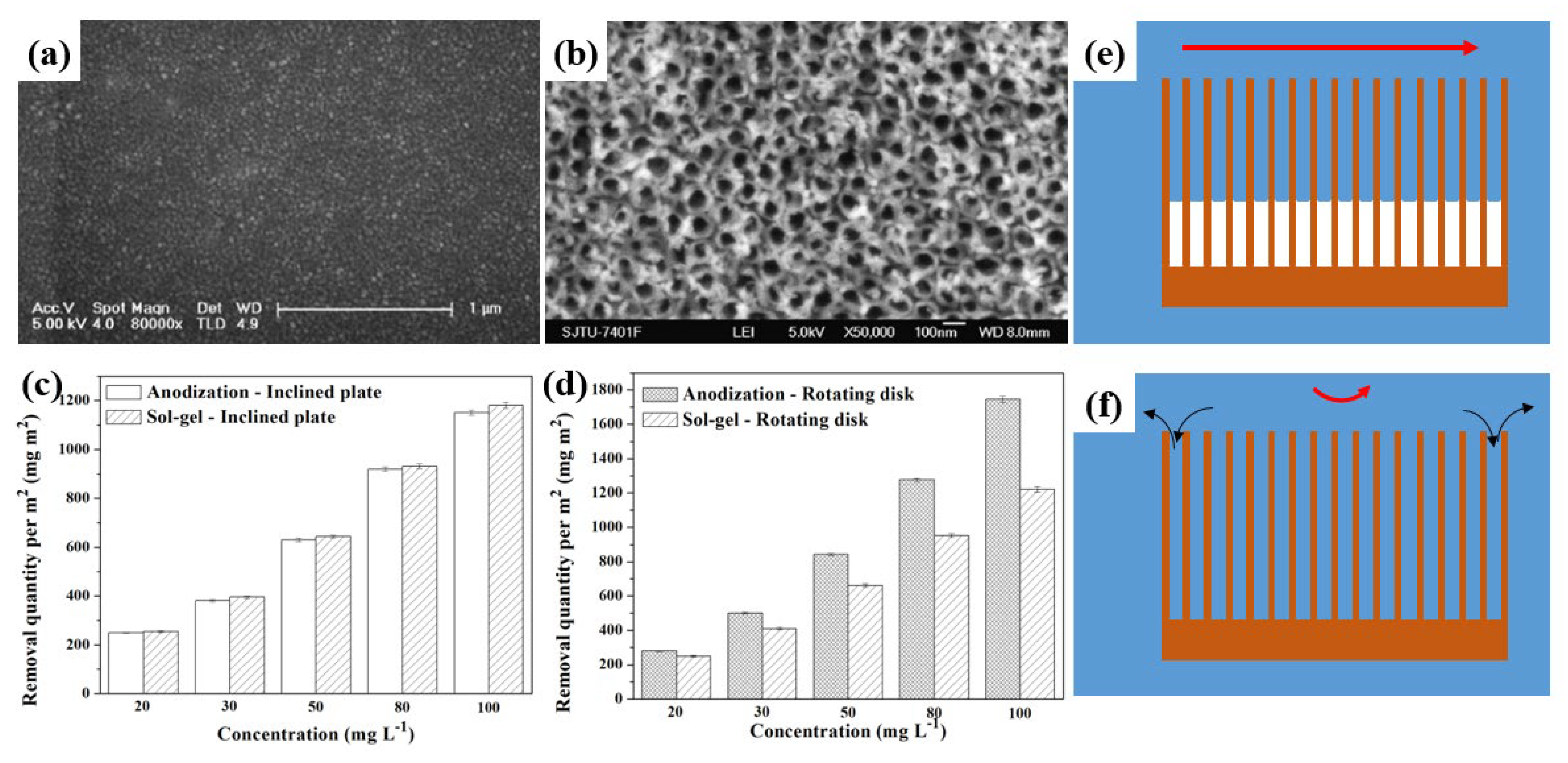
3.2. Synthesis of Supported Catalyst Films with Light-Harvesting Structures

In the aspect of catalyst microstructure control, many kinds of catalysts with light-harvesting structures have been synthesized in the past few years, such as the flower-like structure, hollow spherical structure, and core–shell structure, etc. As a kind of material with a strong photocatalytic activity, BiOCl has been widely studied by researchers in recent years due to its low toxicity and high environmental friendliness [66,67,68,69,70]. At the same time, due to its unique hierarchical structure, it can exhibit a strong light-harvesting performance after a three-dimensional assembly [71,72,73]. Xiong et al. synthesized four morphologies of BiOCl, including an ellipsoid-like structure, sphere-like structure, flower-like structure, and a square-like structure [74,75]. The BiOCl hierarchical nanostructures exhibited excellent shape-dependent visible-light-driven photocatalytic activities for Rhodamine B degradation, which was much higher than that of 2D BiOCl nanosheets, nanoplates, commercial BiOCl, and TiO2 (anatase). A BiOCl micro flower, constructed by ultrathin nanosheets with nearly 100% {001} facets exposed was synthesized by Wang et al. using glycerol as the solvent [76]. The exposed {001} facets terminated with a high density of oxygen atoms and were not only favorable for the adsorption of the cationic dye but they also could accumulate the photogenerated electrons injected from the excited dye. Moreover, the unique layered structure of BiOCl makes it exhibit a satisfying stability. Its stack layer likes a sandwich; [Bi2O2]2+ is between two Cl- ions sheets. They stack together by the weak Van der Waals bonding and strong interlayer covalent bonding. When BiOCl is excited by the irradiation, the bond of Bi-O-Cl can hardly be weakened by the excited antibonding [77]. Many reports have also demonstrated that the BiOCl indeed maintained the photocatalytic activity after several cycles [78,79,80].
Li et al. synthesized β-Bi2O3 thin film with a solid spherical structure on a Ti-based disk through a facile impregnation method [81]. Using it as a precursor, a novel rapid and simple method for preparing BiOCl thin film was proposed (Figure 6a) [82,83]. The precursor dissolution and the intermediate hydrolysis can be controlled simultaneously by changing the pH during the preparation process, so that the reaction rates of the two can be coordinated and matched. Finally, the hierarchical {001} facet exposed by the BiOCl film can be obtained on the Ti disk. Its unique microphotocapture structure makes it exhibit extremely high ultraviolet and visible light catalytic activity. Compared with other granular catalysts, such as TiO2 and β-Bi2O3, the removal of RhB increased by 15 times and 2.5 times, respectively, under visible light (Figure 6b). At the same time, because negatively charged Cl- is distributed in the out layer of BiOCl, it has strong adsorption on pollutants (Figure 6c). The sensitized degradation mechanism of the prepared BiOCl film under visible light is revealed through reactive oxygen species capture and control experiments (Figure 6b). Furthermore, it is combined with the macrophotocapture disk anode to carry out the photocatalytic treatment of different types of industrial wastewater, which can both achieve the standards of direct discharge and reuse [84]. In addition, Cl- in tap water can also be used as the Cl- source, and BiOCl film with the same catalytic performance can also be synthesized by this method without adding additional Cl- [81]. Considering that there is always a certain concentration of Cl- in natural water and industrial wastewater, this method is not only a synthesis method of supported photocatalyst, but it also provides a new idea for the effective removal and resource utilization of Cl- in wastewater [85,86,87].

4. Design of Photo Fuel Cell

In addition to the light energy utilization rate, the photo quantum efficiency is also very important for the photocatalytic reaction. Compound modification of the catalyst to form a heterojunction structure can effectively improve the separation efficiency of photogenerated electrons and holes, but the micro-transfer process of electrons in the catalyst is difficult to further utilize. If the macro-transfer of electrons in the external circuit can be realized, the chemical energy can be further converted into electrical energy to form a fuel cell while the pollutants are degraded. In this process, how to achieve efficient pollutants degradation and electric energy output through the cooperative matching of photoanode and photocathode is a key scientific problem that needs to be solved urgently.

4.1. Synthesis of Supported Catalyst Films with Light-Harvesting Structures

Using the heterojunction formed between semiconductor materials after photoexcitation and noble metals, researchers have constructed a photo fuel cell (PFC) system. Taking TiO2/Ti-Pt PFC as an example (Figure 7a) [88], the photogenerated electrons are transferred to the cathode through the external circuit macroscopically under the action of the potential difference (around 0.8 V) generated by the heterojunction, and the chemical energy is converted into electrical energy while the pollutants are degraded. By changing the cathode surface area and dissolved oxygen concentration and regulating the cathodic oxygen reduction reaction rate, it is found that the electric energy output of PFC is mainly affected by the cathodic oxygen reduction rate. Increasing the oxygen reduction rate can effectively improve the electric energy output characteristics of PFC. For example, as shown in Figure 7b, when the anode/cathode area ratio is reduced from 1/1 to 1/16, not only is the short circuit current density of PFC increased by nearly 2 times, the ff factor is also increased by 1.4 times, and the open circuit potential remains stable. At the same time, the macro-transfer of photogenerated electrons in the external circuit can also promote the degradation of pollutants by the photoanode. For the treatment of various pollutants and actual industrial wastewater, the PFC coulomb efficiency (chemical energy to electric energy conversion efficiency) can reach more than 50%. The generated electric energy can be further utilized. For example, it can provide a bias voltage of 0.60~0.75 V for other photocatalytic reactions, and the effect is the same as that of the direct DC power supply (Figure 7c,d). The constructed PFC system not only provides a new method for the photocatalytic degradation of pollutants, but it also provides a new research idea for the collection and utilization of chemical energy in pollutants.

4.2. Design of Dye-Sensitized Photo Fuel Cell

The matching of the reaction rate between PFC photoanode and cathode is an interesting issue that is worthy of study. In order to make a more efficient use of visible light, Li et al. constructed a dye-sensitized PFC system based on BiOCl photoanode (Figure 8a) [89], and treated a variety of pollutants under the conditions of ultraviolet and visible light irradiation, and studied its electricity generation and photocatalytic degradation performances. By analyzing the electron transfer path, the direct transfer path of ultraviolet excited electrons and the stepwise transfer path of visible sensitized electrons are clarified. Through the analysis of the ff factor, series resistance (Rs) and parallel resistance (Rsh) (Figure 8b), it is found that, compared with direct electron transfer, the gradual transfer of electrons caused by sensitization will lead to an increase in the series resistance of PFC and a decrease in the parallel resistance, thus inhibiting the power generation performance of PFC under visible light conditions. At the same time, different electron transfer paths will also have an impact on the degradation performance of the photoanode. Direct electron transfer can effectively inhibit the recombination of photogenerated electrons and holes, while sensitized stepwise electron transfer does not involve photogenerated holes, and the impact is not obvious. For example, as shown in Figure 8c, the degradation performance of RhB can be increased by 1.5 times in PFC, but it is not affected in sensitized PFC. The photocatalytic degradation and electricity generation performance of BiOCl/Ti dye-sensitized PFC is improved by Niu et al. through regulating the crystal form, crystal facet, and doping of BiOCl [90,91].

4.3. Design of Dual Rotating Disk Photo Fuel Cell

In order to enhance the mass transfer of cathode oxygen, researchers have built a dual rotating disk photo fuel cell system (Figure 9a) [92,93]. Conductive polymers, such as polypyrrole (PPy) and polyaniline (PANI), which are cheap and easy to synthesis, are used as the cathode materials of a rotating disk instead of expensive noble metals. With the increase in the rotating speed, the oxygen mass transfer is strengthened, and the electric energy generation and COD removal performance are improved (Figure 9b) [93]. Compared with Pt, PPy as a cathode can reduce the open-circuit voltage of around 0.3 V, but it can obtain almost the same short-circuit current. At the same time, the nanoarray PPy film owns a larger surface area and lower series resistance. Compared with the planar structure, the electric energy generation and COD degradation performance have been greatly improved (Figure 9c). The above research provide a theoretical basis for further efficient and low-cost matching of PFC photoanodes and cathodes.

5. Multi-Level Utilization of Photogenerated Electrons

The photogenerated electrons macroscopically transferred to the cathode through the external circuit can not only generate electric energy through the four-electron reduction reaction of oxygen, but they also generate H2O2 through the two-electron reduction, which can strengthen the oxidation of organic pollutants. The selection of cathode materials is very important in the process of oxygen reduction reaction (ORR) [94].
In addition to ORR, the photogenerated electrons transferred to the cathode can also generate hydrogen energy through the hydrogen evolution reaction (HER) in the absence of oxygen [95]. How to make the potential difference between cathodes and anodes reaching the hydrogen evolution potential of decomposition water is the key scientific problem to realize the efficient hydrogen production while organic pollutants are degraded in PFC.
At the same time, a large amount of nitrate in wastewater has become another bottleneck restricting the development of enterprises in addition to chemical oxygen demand (COD). The efficient and green selective removal of nitrate in water has gradually become a research hotspot in recent years. The direct reduction of nitrate at the cathode is limited by the hydrogen evolution reaction and the mass transfer of intermediate products, resulting in ammonia as the main product [96]. How to further realize the selective reduction of nitrate to nitrogen in the cathode system has also attracted more and more of researchers’ attention in recent years.

5.1. H2O2 Production at Cathode in Dual Rotating Disk Reactor

Although the thin film rotating disk photocatalytic reactor has a high light utilization rate, the photogenerated electrons and holes are still easy to recombine. Photogenerated electrons are transferred to the cathode by applying bias voltage, and a photoelectrocatalytic system is established, which can effectively avoid the recombination of photogenerated electrons and holes [97,98,99]. The research shows that when treating a 55 mL 20 mg L−1 RhB solution for 90 min, the rotating disk photoelectrocatalytic reactor can improve the decolorization rate from 30% to more than 90% compared with the rotating disk photocatalytic reactor [55]. Based on this, Xu et al. designed a photoelectrocatalytic rotating disk reactor without the bias voltage [100]. The reactor is composed of a TiO2/Ti disk photoanode and a Cu disk cathode. The two disks are connected by wires. The ultraviolet light is irradiated on the TiO2 surface to generate electrons. The electrons are spontaneously transferred to the Cu disk through the Schottky barrier, and they react with O2 to generate H2O2. The decolorization rate and total organic carbon (TOC) removal rate of 55 mL 50 mg L−1 RhB were 87.9% and 53.4%, respectively, after being treated with the TiO2/Ti-Cu dual rotating disk reactor for 60 min, which exhibits a good application prospect.

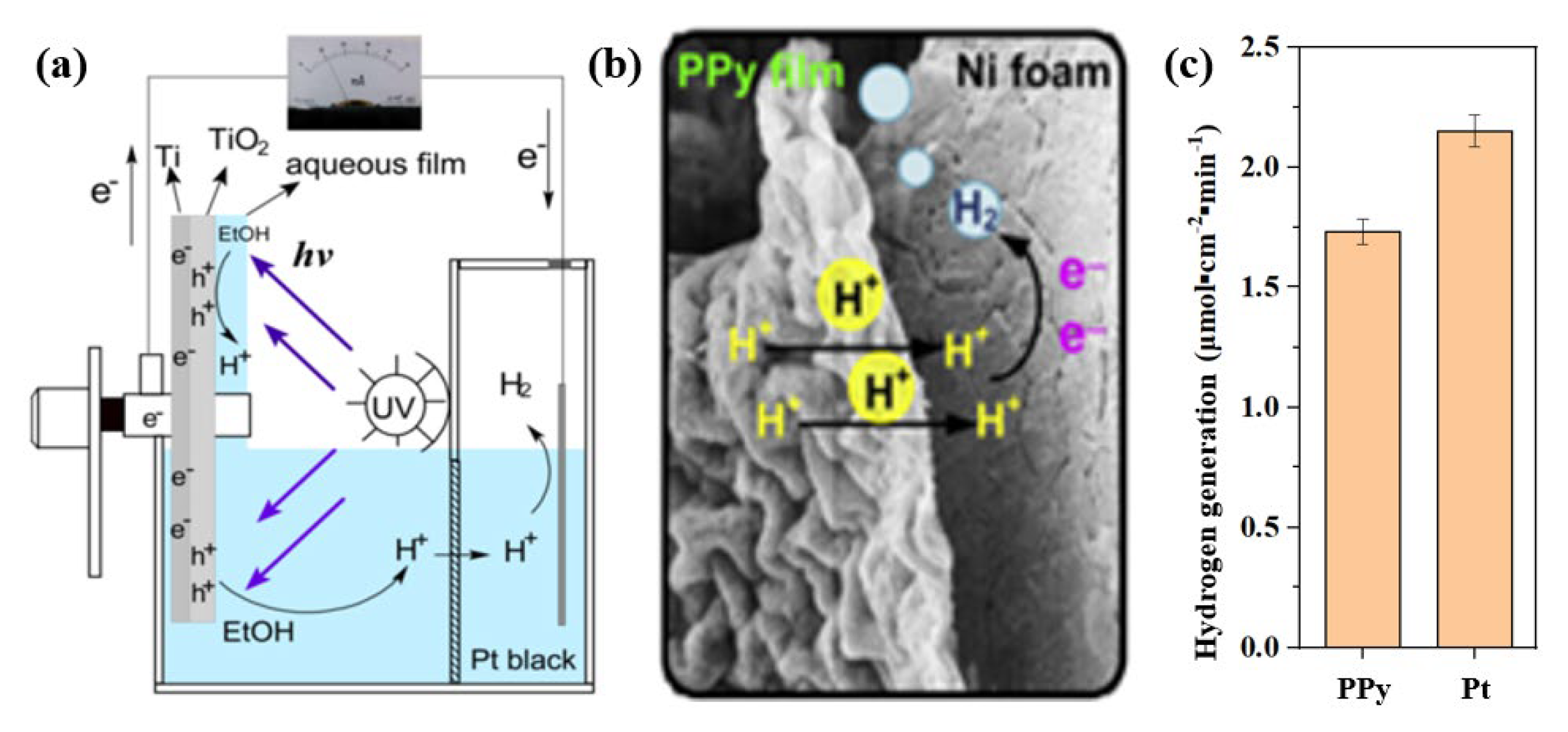
5.2. H2 Production at Cathode in Rotating Disk Reactor

In terms of hydrogen production, on the one hand, the potential difference between anodes and cathodes can be increased by adjusting the pH of anode and cathode cells, so as to realize hydrogen production while the organic pollutants are degraded in PFC [101,102,103]. As shown in Figure 10, Tang et al. successfully provide an additional potential of around 0.4~0.6 V by adjusting the pH difference between the anode and cathode cells, so as to increase the hydrogen production of the PPy cathode in a rotating disk reactor (1.75 μmol cm−2 min−1), which can achieve the level obtained by the pure Pt cathode (2.20 μmol cm−2 min−1). The system was successfully applied in real industrial wastewater containing alcohol. A stable H2 production performance can be obtained when the alcohol is degraded. When using Chinese rice wine as a substrate at the same ethanol content level (i.e., 0.1 mol L−1), the production of H2 is close to that of the pure ethanol solution, but no hydrogen is detected in the conventional submerged reactor [102].
On the other hand, efficient hydrogen evolution catalysts are still the main research focus of researchers. Li and his co-workers innovatively used acetic acid as a template to synthesize high 1T phase exposed MoS2 nanosheets with vertical array structures on carbon cloth through a facile one-step solvothermal process [104]. Compared with MoS2 prepared without acetic acid, when the current density is 10 mA cm−2, the over potential can be reduced to 136 mV, the Tafel slope is only 45 mV dec−1, and the hydrogen production rate can be increased to 92% of the pure Pt cathode. The mechanism of acetic acid was deeply studied by in situ infrared spectroscopy. It was found that its weak dissociation characteristics could effectively control the pH change in the reaction process, providing more nucleation sites for the growth of MoS2 on carbon cloth. At the same time, carboxyl functional groups can also reduce the surface energy of MoS2 and prevent its aggregation to form 2H phase with poor hydrogen evolution performance. This research not only provides a new application field for PFC, that is, the photocatalytic degradation of pollutants and the generation of hydrogen energy, but also provides a theoretical basis for the selective reduction of nitrate or other pollutants.

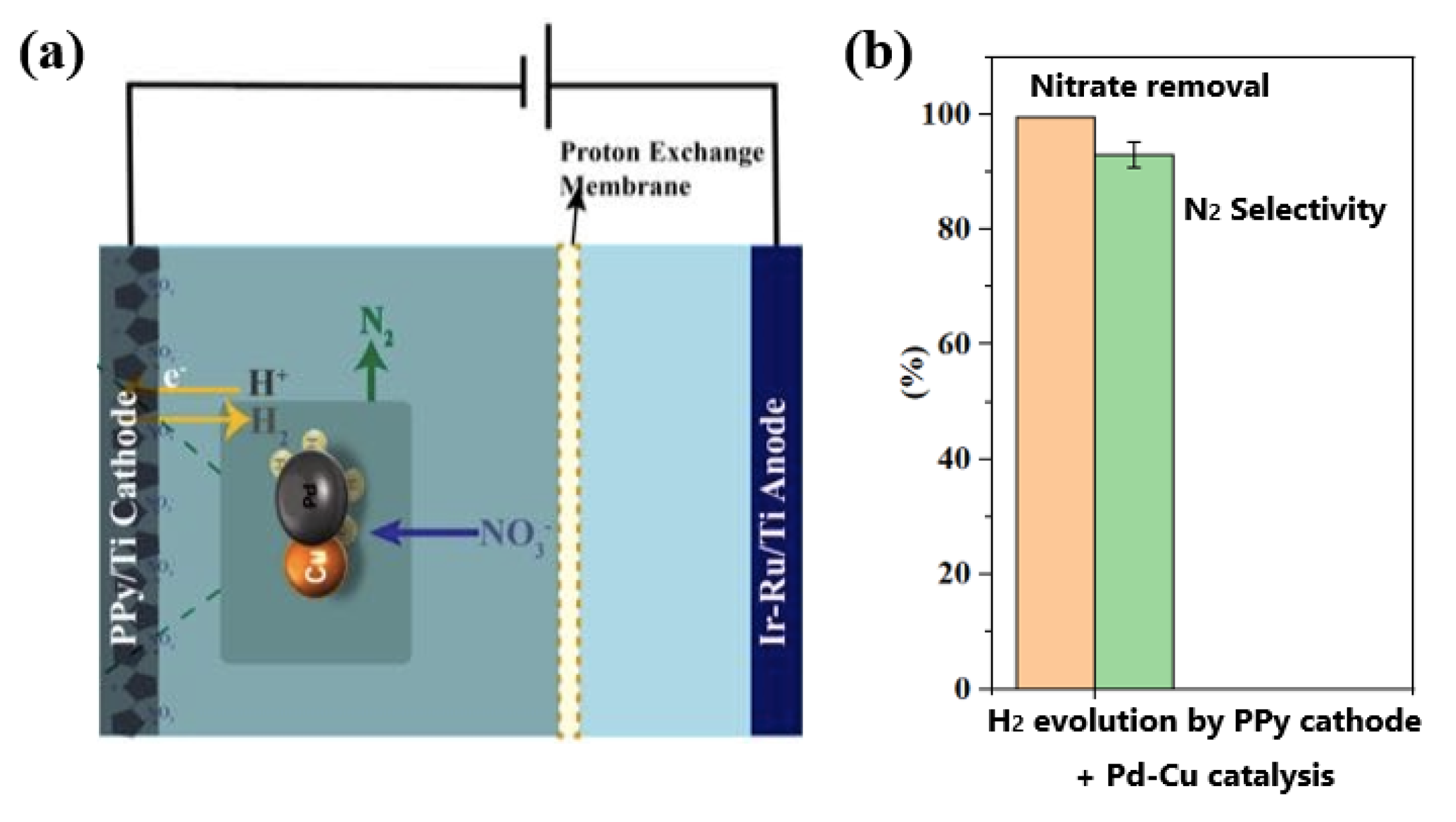
5.3. Cathodic Hydrogen Production Combined with Nitrate Reduction

In terms of nitrate reduction, Jia et al. revealed the kinetic mechanism of ammonia as the main cathodic reduction product by studying various cathode materials (Co3O4, CuO, Fe2O3, NiO, etc.) [105,106]. That is, affected by the side reaction of hydrogen ion activation, the first-order reaction of generating ammonia is easier to occur, while the second-order reaction of generating nitrogen is limited by the kinetic mass transfer of intermediate products (such as nitrite), which is difficult to occur. Therefore, it is necessary to add a large amount of Cl- and realize the oxidation of ammonia to nitrogen under the combined action of anode in previous studies. In order to realize the direct conversion of nitrate to nitrogen, Chen et al. used the hydrogen generated by the cathode as a reducing agent, and in situ combined with the Cu-Pd catalyst to realize the efficient selective reduction of nitrate to nitrogen (Figure 11a) [107,108]. The selection of the cathode catalyst is very important in this process. It has been found that the PPy cathode not only has an excellent hydrogen production performance, but also has a strong repulsive effect on nitrate and other anions when it is used as a cathode due to the anion occupation doping in the polymerization process, which can selectively produce hydrogen without reducing nitrate to ammonia. On this basis, in combination with the Cu-Pd catalyst, compared with external hydrogen supply, in situ hydrogen production is not only sager and more controllable, but it is also more dispersed and has a higher reduction activity. The nitrogen selectivity can reach 93% after optimization (Figure 11b), which is much higher than the Cu-Pd catalytic system reported in other literatures, and no additional Cl- is needed. Moreover, the system was applied in real industrial electroplating wastewater treatment, and the total nitrogen can be effectively removed [107]. The NO3--N (670 mg L−1) is reduced to less than 100 mg L−1 after 90 min under 50 mA, and very little amount of NH4+-N is generated.
On this basis, in order to reduce the amount of precious metal Pd, Shi et al. carried out a loading study on the Cu-Pd catalyst [109]. It was found that Cu-Pd particles with a high dispersion (average particle size 2 nm) could be obtained on the metal oxide support by stepwise annealing, which not only had a fast nitrate reduction rate, but also had a nitrogen selectivity of more than 70%. Further, through in situ characterization and DFT calculation, the interaction mechanism between the support and Cu-Pd particles was studied [110], and it was revealed that the Lewis acid site is conducive to the formation of the -O-Cu+-Pd+- structure, in which the -O-Cu+- site is more conducive to the reduction of nitrate, while the unsaturated -Pd+- site is more conducive to the adsorption of intermediate products (such as nitrite), providing a favorable starting condition for the secondary reaction of nitrogen generation. The above research provide a new way for the selective reduction of nitrate by photocatalysis.

6. Conclusions

Photocatalytic technique is a promising wastewater treatment technique because it does not require additional chemicals and has a strong oxidation ability. However, the low light energy utilization rate and photo quantum efficiency greatly limit its further practical application. In view of these tow bottlenecks, and based on the rotating disk thin solution film reactor, this work reviews the latest research progress in photogenerated electrons’ light-harvesting excitation, photogenerated electrons’ macro-transfer, and photogenerated electrons’ multi-level utilization, providing theoretical guidance for the further application of photocatalytic technique in wastewater treatment.
In addition to the efficient use of photogenerated electrons, there are still some other key issues that need to be solved before the photocatalytic technique can be really applied in wastewater treatment. These issues include the following:
(1)
Research and development of low-cost, large-scale, efficient, and stable photoanodes. The catalyst needs to be loaded on the surface of the photoanode substrate in a thin solution film reactor. Therefore, not only is the supported photocatalyst with stable performance and low-cost needed, but also the photoanode substrate needs to be optimized in the process of photoanode preparation. The Ti plate is mostly used as anode substrate in most of the current research, and the catalyst layer can be firmly grown on its surface after acidic etching, but the cost of large-scale application is quite high. The combination of corrosion resistance and low-cost anode substrates and efficient photocatalyst film is the prerequisite for the application of the photocatalytic technique in the field of wastewater treatment.
(2)
Further optimization and model construction of thin film photocatalytic reactors. The thin solution film reactor has been proved to be the most effective reactor in the photocatalytic water treatment process, but its further enlargement still needs to consider many issues, such as floor area, light sources selection, and energy consumption. The development of the corresponding model can help to further enlarge and optimize the reaction device.
(3)
Multi-technique coupling realizes the deep and collaborative treatment of pollutants in wastewater. The photocatalytic technique has an extremely strong oxidation ability and can efficiently mineralize organic pollutants, but its removal rate is often slow due to the mass transfer limitation of heterogeneous reactions. Therefore, photocatalysis can be combined with other homogeneous oxidation processes, such as the Fenton process, to realize the rapid mineralization of organic pollutants. On the other hand, in addition to organic pollutants, wastewater contains other types of pollutants, such as inorganic salts, heavy metals, etc. How to use the photogenerated holes and electrons to achieve the simultaneous removal of multiple pollutants is also an issue that is worth studying in the future.
(4)
Studies on the effect of actual wastewater on the photocatalytic process. Most of the research uses simulated pollutants to investigate the photocatalytic performance of the catalyst at present, but the water quality conditions of the actual wastewater are often much more complex. Therefore, different types of actual wastewater should be used as the research objective to improve the stability of the photocatalytic technique in the future.

Author Contributions

Writing—original draft, Z.J.; writing—review and editing, K.L.; supervision, J.J. All authors have read and agreed to the published version of the manuscript.

Funding

This research was funded by the National Natural Science Foundation of China (No. 22176126, 21976119 and 22106103) and the National Science Foundation of Shanghai (No. 21ZR1430200).

Conflicts of Interest

The authors declare no conflict of interest.

References

  1. Ong, W.J.; Tan, L.L.; Ng, Y.H.; Yong, S.T.; Chai, S.P. Graphitic Carbon Nitride (g-C3N4)-Based Photocatalysts for Artificial Photosynthesis and Environmental Remediation: Are We a Step Closer To Achieving Sustainability? Chem. Rev. 2016, 116, 7159–7329. [Google Scholar] [CrossRef] [PubMed]
  2. Fijishima, A.; Rao, T.N.; Tryk, D.A. Titanium dioxide photocatalysis. J. Photochem. Photobiol. C 2000, 1, 1–21. [Google Scholar] [CrossRef]
  3. Gaya, U.I.; Abdullah, A.H. Heterogeneous photocatalytic degradation of organic contaminants over dioxide: A review of fundamentals, progress and problems. J. Photochem. Photobiol. C 2008, 8, 1–12. [Google Scholar] [CrossRef]
  4. Yuan, J.; Zhang, Y.Q.; Zhou, L.Y.; Zhang, G.C.; Yip, H.L.; Lau, T.K.; Lu, X.H.; Zhu, C.; Peng, H.J.; Johnson, P.A. Single-Junction Organic Solar Cell with over 15% Efficiency Using Fused-Ring Acceptor with Electron-Deficient Core. Joule 2019, 3, 1140–1151. [Google Scholar] [CrossRef]
  5. Jiang, Q.; Zhao, Y.; Zhang, X.W.; Yang, X.L.; Chen, Y.; Chu, Z.M.; Ye, Q.F.; Li, X.X.; Yin, Z.G.; You, J.B. Surface passivation of perovskite film for efficient solar cells. Nat. Photonics 2019, 13, 460–466. [Google Scholar] [CrossRef]
  6. Efficient Photochemical Water Splitting by a Chemically Modified n-TiO2. Science 2002, 297, 2243–2245. [CrossRef]
  7. Li, X.; Yu, J.G.; Jaroniec, M.; Chen, X.B. Cocatalysts for Selective Photoreduction of CO2 into Solar Fuels. Chem. Rev. 2019, 119, 3962–4179. [Google Scholar] [CrossRef]
  8. Xu, Q.L.; Zhang, L.Y.; Cheng, B.; Fan, J.J.; Yu, J.G. S-Scheme Heterojunction Photocatalyst. Chem 2020, 6, 1543–1559. [Google Scholar] [CrossRef]
  9. Qian, G.P.; Yu, H.N.; Gong, X.B.; Zhao, L. Impact of Nano-TiO2 on the NO2 degradation and rheological performance of asphalt pavement. Constr. Build. Mater. 2019, 218, 53–63. [Google Scholar] [CrossRef]
  10. Xu, Y.D.; Jin, R.Y.; Hu, L.; Li, B.; Chen, W.; Shen, J.S.; Wu, P.; Fang, J.K. Studying the mix design and investigating the photocatalytic performance of pervious concrete containing TiO2-Soaked recycled aggregates. J. Clean. Prod. 2020, 248, 119281. [Google Scholar] [CrossRef]
  11. Zhu, T.X.; Cheng, Y.; Huang, J.Y.; Xiong, J.Q.; Ge, M.; Mao, J.J.; Liu, Z.; Dong, X.L.; Chen, Z.; Lai, Y.K. A transparent superhydrophobic coating with mechanochemical robustness for anti-icing, photocatalysis and self-cleaning. Chem. Eng. J. 2020, 399, 125746. [Google Scholar] [CrossRef]
  12. Ma, W.J.; Li, Y.S.; Zhang, M.J.; Gao, S.T.; Cui, J.X.; Huang, C.B.; Fu, G.D. Biomimetic Durable Multifunctional Self-Cleaning Nanofibrous Membrane with Outstanding Oil/Water Separation, Photodegradation of Organic Contaminants, and Antibacterial Performances. ACS Appl. Mater. Interfaces 2020, 12, 34999–35010. [Google Scholar] [CrossRef]
  13. Xia, P.F.; Cao, S.W.; Zhu, B.C.; Liu, M.J.; Shi, M.S.; Yu, J.G.; Zhang, Y.F. Designing a 0D/2D S-Scheme Heterojuction over Polymeric Carbon Nitride for Visible-Light Photocatalytic Inactivation of Bacteria. Angew. Chem. Int. Edit. 2020, 59, 5218–5225. [Google Scholar] [CrossRef]
  14. Lv, D.; Wang, R.X.; Tang, G.S.; Mou, Z.P.; Lei, J.D.; Han, J.Q.; De Smedt, S.; Xiong, R.H.; Huang, C.B. Ecofriendly Electrospun Membranes Loaded with Visible-Light Responding Nanoparticles for Multifunctional Usages: Highly Efficient Air Filtration, Dye Scavenging, and Bactericidal Activity. ACS Appl. Mater. Interfaces 2019, 11, 12880–12889. [Google Scholar] [CrossRef] [Green Version]
  15. Zeghioud, H.; Assadi, A.A.; Khellaf, N.; Djelal, H.; Amrane, A.; Rtimi, S. Reactive species monitoring and their contribution for removal of textile effluent with photocatalysis under UV and visible lights: Dynamic and mechanism. J. Photochem. Photobiol. A 2018, 365, 94–102. [Google Scholar] [CrossRef]
  16. Rueda-Marquez, J.J.; Levchuk, I.; Ibanez, P.F.; Sillanpaa, M. A critical review on application of photocatalysis for toxicity reduction of real wastewaters. J. Clean. Prod. 2020, 258, 120694. [Google Scholar] [CrossRef]
  17. Al-Mamun, M.R.; Kader, S.; Islam, M.S.; Khan, M.Z.H. Photocatalytic activity improvement and application of UV-TiO2 photocatalysis in textile wastewater treatment: A review. J. Environ. Chem. Eng. 2019, 7, 103248. [Google Scholar] [CrossRef]
  18. Lai, C.; Zhang, M.M.; Li, B.S.; Huang, D.L.; Zeng, G.M.; Qin, L.; Liu, X.G.; Yi, H.; Cheng, M.; Li, L.; et al. Fabrication of CuS/BiVO4 (040) binary heterojunction photocatalysts with enhanced photocatalytic activity for Ciprofloxacin degradation and mechanism insight. Chem. Eng. J. 2018, 358, 891–902. [Google Scholar] [CrossRef]
  19. Wang, J.L.; Zhuan, R. Degradation of antibiotics by advanced oxidation processes: An overview. Sci. Total Environ. 2019, 701, 135023. [Google Scholar] [CrossRef]
  20. Li, S.J.; Chen, J.L.; Hu, S.W.; Wang, H.L.; Jiang, W.; Chen, X.B. Facile construction of novel Bi2WO6/Ta3N5 Z-scheme heterojunction nanofibers for efficient degradation of harmful pharmaceutical pollutants. Chem. Eng. J. 2020, 402, 126165. [Google Scholar] [CrossRef]
  21. Chong, M.N.; Jin, B.; Chow, C.W.K.; Saint, C. Recent developments in photocatalytic water treatment technology: A review. Water Res. 2010, 44, 2997–3027. [Google Scholar] [CrossRef] [PubMed]
  22. Zhang, J.; Yang, P.L.; Zheng, J.L.; Li, J.; Fu, Q.; He, Y.N.; Zou, Y.N.; Wu, X.H.; Cheng, C.X.; Wang, F. Enhanced carbon dioxide reduction in a thin-film rotating disk photocatalytic fuel cell reactor. J. CO2 Util. 2020, 37, 328–334. [Google Scholar] [CrossRef]
  23. Darvish, S.M.; Ali, A.M.; Sani, S.R. Designed air purifier reactor for photocatalytic degradation of CO2 and NO2 gases using MWCNT/TiO2 thin films under visible light irradiation. Mater. Chem. Phys. 2020, 248, 122872. [Google Scholar] [CrossRef]
  24. Jin, J.; Wang, C.; Ren, X.N.; Huang, S.Z.; Wu, M.; Chen, L.H.; Hasan, T.; Wang, B.J.; Li, Y.; Su, B.L. Anchoring ultrafine metallic and oxidized Pt nanoclusters on yolk-shell TiO2 for unprecedentedly high photocatalytic hydrogen production. Nano Energy 2017, 38, 118–126. [Google Scholar] [CrossRef] [Green Version]
  25. Yin, H.B.; Chen, X.F.; Hou, R.J.; Zhu, H.J.; Li, S.Q.; Huo, Y.N.; Li, H.X. Ag/BiOBr Film in a Rotating-Disk Reactor Containing Long-Afterglow Phosphor for Round-the Clock Photocatalysis. ACS Appl. Mater. Interfaces 2015, 7, 20076–20082. [Google Scholar] [CrossRef]
  26. Yoneda, Y.; Goto, A.; Takeda, N.; Harada, H.; Kondo, M.; Miyasaka, H.; Nagasawa, Y.; Dewa, T. Ultrafast Photodynamics and Quantitative Evaluation of Biohybrid Photosynthetic Antenna and Reaction Center. J. Phys. Chem. C 2020, 124, 8605–8615. [Google Scholar] [CrossRef]
  27. Xiao, M.; Wang, Z.L.; Lyu, M.Q.; Luo, B.; Wang, S.C.; Liu, G.; Cheng, H.M.; Wang, L.Z. Hollow Nanostructures for Photocatalysis: Advantages and Challenges. Adv. Mater. 2019, 31, 1801369. [Google Scholar] [CrossRef]
  28. Gao, C.; Low, J.X.; Long, R.; Kong, T.T.; Zhu, J.F.; Xiong, Y.J. Heterogeneous Single-Atom Photocatalysts: Fundamentals and Applications. Chem. Rev. 2020, 120, 12175–12216. [Google Scholar] [CrossRef]
  29. Zhang, W.H.; Mohamed, A.R.; Ong, W.J. Z-Scheme Photocatalytic Systems for Carbon Dioxide Reduction: Where Are We Now? Angew. Chem. Int. Edit. 2020, 59, 22894–22915. [Google Scholar] [CrossRef]
  30. Biswal, B.P.; Vignolo-Gonzalez, H.A.; Banerjee, T.; Grunenberg, L.; Savasci, G.; Gottschling, K.; Nuss, J.; Ochsenfeld, C.; Lotsc, B.V. Sustained Solar H2 Evolution from a Thiazolo[5,4-d]thiazole-Bridged Covalent Organic Framework and Nickel-Thiolate Cluster in Water. J. Am. Chem. Soc. 2019, 141, 11082–11092. [Google Scholar] [CrossRef] [Green Version]
  31. Reddy, N.L.; Rao, V.N.; Vijayakumar, M.; Santhosh, R.; Anandan, S.; Karthik, M.; Shankar, M.V.; Reddy, K.R.; Shetti, N.P.; Nadagouda, M.N. A review on frontiers in plasmonic nano-photocatalysts for hydrogen production. Int. J. Hydrogen Energ. 2019, 44, 10453–10472. [Google Scholar] [CrossRef]
  32. Han, Y.Q.; Xu, H.T.; Su, Y.Q.; Xu, Z.L.; Wang, K.F.; Wang, W.Z. Noble metal (Pt, Au@Pd) nanoparticles supported on metal organic framework (MOF-74) nanoshuttles as high-selectivity CO2 conversion catalysts. J. Catal. 2019, 370, 70–78. [Google Scholar] [CrossRef]
  33. He, F.; Meng, A.Y.; Cheng, B.; Ho, W.K.; Yu, J.G. Enhanced photocatalytic H2-production activity of WO3/TiO2 step-scheme heterojunction by graphene modification. Chinese J. Catal. 2019, 41, 9–20. [Google Scholar] [CrossRef]
  34. Hu, T.P.; Dai, K.; Zhang, J.F.; Chen, S.F. Noble-metal-free Ni2P modified step-scheme SnNb2O6/CdS-diethylenetriamine for photocatalytic hydrogen production under broadband light irradiation. Appl. Catal. B-Environ. 2020, 269, 118844. [Google Scholar] [CrossRef]
  35. Singh, P.; Shandilya, P.; Raizada, P.; Sudhaik, A.; Rahmani-Sani, A.; Hosseini-Bandegharaei, A. Review on various strategies for enhancing photocatalytic activity of graphene based nanocomposites for water purification. Arab. J. Chem. 2020, 13, 3498–3520. [Google Scholar] [CrossRef]
  36. Tobaldi, D.M.; Dvoranova, D.; Lajaunie, L.; Rozman, N.; Figueiredo, B.; Seabra, M.P.; Skapin, A.S.; Calvino, J.J.; Brezova, V.; Labrincha, J.A. Graphene-TiO2 hybrids for photocatalytic aided removal of VOCs and nitrogen oxides from outdoor environment. Chem. Eng. J. 2021, 405, 126651. [Google Scholar] [CrossRef]
  37. Gao, B.W.; Sun, M.X.; Ding, W.; Ding, Z.P.; Liu, W.Z. Decoration of gamma-graphyne on TiO2 nanotube arrays: Improved photoelectrochemical and photoelectrocatalytic properties. Appl. Catal. B-Environ. 2020, 281, 119492. [Google Scholar] [CrossRef]
  38. Ye, S.S.; Chen, Y.X.; Yao, X.L.; Zhang, J.D. Simultaneous removal of organic pollutants and heavy metals in wastewater by photoelectrocatalysis: A review. Chemosphere 2021, 273, 128503. [Google Scholar] [CrossRef]
  39. Shan, B.; Vanka, S.; Li, T.T.; Troian-Gautier, L.; Brennaman, M.K.; Mi, Z.T.; Meyer, T.J. Ninary molecular-semiconductor p-n junctions for photoelectrocatalytic CO2 reduction. Nat. Energy 2019, 4, 290–299. [Google Scholar] [CrossRef]
  40. Huang, S.; Ouyang, Y.; Zheng, B.F.; Dan, M.; Liu, Z.Q. Enhanced Photoelectrocatalytic Activities for CH3OH-to-HCHO Conversion on Fe2O3/MoO3: Fe-O-Mo Covalency Dominates the Intrinsic Activity. Angew. Chem. Int. Edit. 2021, 60, 9546–9552. [Google Scholar] [CrossRef]
  41. Oli, H.B.; Kim, A.A.; Park, M.; Bhattarai, D.P.; Pant, B. Photocatalytic Fuel Cells for Simultaneous Wastewater Treatment and Power Generation: Mechanisms, Challenges, and Future Prospects. Energies 2022, 15, 3216. [Google Scholar] [CrossRef]
  42. Parvizi, T.; Parsa, J.B. High-efficient photocatalytic fuel cell integrated with periodate activation for electricity production by degradation of refractory organics. J. Power Sources 2021, 484, 229264. [Google Scholar] [CrossRef]
  43. Andrade, T.S.; Dracopoulos, V.; Keramidas, A.; Pereira, M.C.; Lianos, P. Charging a vanadium redox battery with a photo(catalytic) fuel cell. Sol. Energ. Mat. Sol. C. 2021, 221, 110889. [Google Scholar] [CrossRef]
  44. Gui, Y.; Cao, Y.; Li, G.; Ai, X.; Gao, X.; Yang, H. A solar storable fuel cell with efficient photo-degradation of organic waste for direct electricity generation. Energy Storage Mater. 2016, 5, 165–170. [Google Scholar] [CrossRef]
  45. Jia, Y.H.; Zhang, D.D.; You, H.; Li, W.G.; Jiang, K. Benthic microbial fuel cell equipped with a photocatalytic Cu2O-coated cathode. J. Nanopart. Res. 2019, 21, 3. [Google Scholar] [CrossRef]
  46. Stephan, B.; Ludovic, L.; Dominique, W. Modelling of a falling thin film deposited photocatalytic step reactor for water purification: Pesticide treatment. Chem. Eng. J. 2011, 169, 216–225. [Google Scholar] [CrossRef]
  47. Xu, Y.L.; Zhong, D.J.; Jia, J.P.; Chen, S.; Li, K. Enhanced dye wastewater degradation efficiency using a flowing aqueous film photoelectrocatalytic reactor. J. Environ. Sci. Health A 2008, 43, 1215–1222. [Google Scholar] [CrossRef]
  48. Xu, Y.; Zhong, D.; Jia, J.; Li, K.; Li, J.; Quan, X. Dual slant-placed electrodes thin-film photocatalytic reactor: Enhanced dye degradation efficiency by self-generated electric field. Chem. Eng. J. 2013, 225, 138–143. [Google Scholar] [CrossRef]
  49. Xu, Y.; Jia, J.; Zhong, D.; Wang, Y. Degradation of dye wastewater in a thin-film photoelectrocatalytic (PEC) reactor with slant-placed TiO2/Ti anode. Chem. Eng. J. 2009, 150, 302–307. [Google Scholar] [CrossRef]
  50. Admas, M.; Campbell, I.; Robertson, P.K.J. Novel Photocatalytic Reactor Development for Removal of Hydrocarbons from Water. Int. J. Photoenergy 2008, 2008, 674537. [Google Scholar] [CrossRef] [Green Version]
  51. Dionysiou, D.D.; Balasubramanian, G.; Suidan, M.T.; Khodadoust, A.P.; Baudin, I.; Laîné, J.-M. Rotating disk photocatalytic reactor: Development, characterization, and evaluation for the destruction of organic pollutants in water. Water Res. 2000, 34, 2927–2940. [Google Scholar] [CrossRef]
  52. Dionysiou, D.D.; Suidan, M.T.; Baudin, I.; Laîné, J.-M. Oxidation of organic contaminants in a rotating disk photocatalytic reactor: Reaction kinetics in the liquid phase and the role of mass transfer base on the dimensionless Damköhler number. Appl. Catal. B Environ. 2002, 38, 1–16. [Google Scholar] [CrossRef]
  53. Dionysiou, D.D.; Burbano, A.A.; Suidan, M.T.; Baudin, I.; Laîné, J.-M. Effect of Oxygen in a Thin-Film Rotating Disk Photocatalytic Reactor. Environ. Sci. Technol. 2002, 36, 3834–3843. [Google Scholar] [CrossRef]
  54. Dionysiou, D.D.; Khodadoust, A.P.; Kern, A.M.; Suidan, M.T.; Baudin, I.; Laîné, J.-M. Continuous-mode photocatalytic degradation of chlorinated phenols and pesticides in water using a bench-scale TiO2 rotating disk reactor. Appl. Catal. B Environ. 2000, 24, 139–155. [Google Scholar] [CrossRef]
  55. Xu, Y.; He, Y.; Cao, X.; Zhong, D.; Jia, J. TiO2/Ti Rotating Disk Photoelectrocatalytic (PEC) Reactor: A Combination of Highly Effective Thin-Film PEC and Conventional PEC Processes on a Single Electrode. Environ. Sci. Technol. 2008, 42, 2612–2617. [Google Scholar] [CrossRef]
  56. Zhang, A.; Zhou, M.; Han, L.; Zhou, Q. The combination of rotating disk photocatalytic reactor and TiO2 nanotube arrays for environmental pollutants removal. J. Hazard. Mater. 2011, 186, 1374–1383. [Google Scholar] [CrossRef]
  57. Huo, Y.; Chen, X.; Zhang, J.; Pan, G.; Jia, J.; Li, H. Ordered macroporous Bi2O3/TiO2 film coated on a rotating disk with enhanced photocatalytic activity under visible irradiation. Appl. Catal. B Environ. 2014, 148–149, 550–556. [Google Scholar] [CrossRef]
  58. Boiarkina, I.; Pedron, S.; Patterson, D.A. An experimental and modelling investigation of the effect of the flow regime on the photocatalytic degradation of methylene blue on a thin film coated ultraviolet irradiated spinning disc reactor. Appl. Catal. B Environ. 2011, 110, 14–24. [Google Scholar] [CrossRef] [Green Version]
  59. Boiarkina, I.; Norris, S.; Patterson, D.A. The case for the photocatalytic spinning disc reactor as a process intensification technology: Comparison to an annular reactor for the degradation of methylene blue. Chem. Eng. J. 2013, 225, 752–765. [Google Scholar] [CrossRef] [Green Version]
  60. Boiarkina, I.; Norris, S.; Patterson, D.A. Investigation into the effect of flow structure on the photocatalytic degradation of methylene blue and dehydroabietic acid in a spinning disc reactor. Chem. Eng. J. 2013, 222, 159–171. [Google Scholar] [CrossRef] [Green Version]
  61. Zhang, L.; Kanki, T.; Sano, N.; Toyoda, A. Photocatalytic degradation of organic compounds in aqueous solution by a TiO2-coated rotating-drum reactor using solar light. Sol. Energy 2001, 70, 331–337. [Google Scholar] [CrossRef]
  62. Damodar, R.A.; Swaminathan, T. Performance evaluation of a continuous flow immobilized rotating tube photocatalytic reactor (IRTPR) immobilized with TiO2 catalyst for azo dye degradation. Chem. Eng. J. 2008, 144, 59–66. [Google Scholar] [CrossRef]
  63. Yao, Y.; Li, K.; Chen, S.; Jia, J.; Wang, Y.; Wang, H. Decolorization of Rhodamine B in a thin-film photoelectrocatalytic (PEC) reactor with slant-placed TiO2 nanotubes electrode. Chem. Eng. J. 2012, 187, 29–35. [Google Scholar] [CrossRef]
  64. Li, K.; He, Y.; Xu, Y.; Wang, Y.; Jia, J. Degradation of Rhodamine B Using an Unconventional graded Photoelectrode with Wedge Structure. Environ. Sci. Technol. 2011, 45, 7401–7407. [Google Scholar] [CrossRef] [PubMed]
  65. Li, K.; Yang, C.; Wang, Y.; Jia, J.; Xu, Y.; He, Y. A High-Efficient Rotating Disk Photoelectrocatalytic (PEC) Reactor with Macro Light Harvesting Pyramid-Surface Electrode. AIChE J. 2012, 58, 2448–2455. [Google Scholar] [CrossRef]
  66. Li, M.; Yu, S.X.; Huang, H.W.; Li, X.W.; Feng, Y.B.; Wang, C.; Wang, Y.G.; Ma, T.Y.; Guo, L.; Zhang, Y.H. Unprecedented Eighteen-Faceted BiOCl with a Ternary Facet Junction Boosting Cascade Charge Flow and Photo-redox. Angew. Chem. Int. Edit. 2019, 58, 9517–9521. [Google Scholar] [CrossRef]
  67. Jiang, R.R.; Lu, G.H.; Yan, Z.H.; Wu, D.H.; Zhou, R.R.; Bao, X.H. Insights into a CQD-SnNb2O6/BiOCl Z-scheme system for the degradation of benzocaine: Influence factors, intermediate toxicity and photocatalytic mechanism. Chem. Eng. J. 2019, 374, 79–90. [Google Scholar] [CrossRef]
  68. Wang, H.X.; Liao, B.; Lu, T.; Ai, Y.; Liu, G. Enhanced visible-light photocatalytic degradation of tetracycline by a novel hollow BiOCl@CeO2 heterostructured microspheres: Structural characterization and reaction mechanism. J. Hazard. Mater. 2020, 385, 121552. [Google Scholar] [CrossRef]
  69. Wu, S.S.; Yu, X.; Zhang, J.L.; Zhang, Y.M.; Zhu, Y.; Zhu, M.S. Construction of BiOCl/CuBi2O4S-scheme heterojunction with oxygen vacancy for enhanced photocatalytic diclofenac degradation and nitric oxide removal. Chem. Eng. J. 2021, 411, 128555. [Google Scholar] [CrossRef]
  70. Jia, Z.H.; Li, T.; Zheng, Z.F.; Zhang, J.D.; Liu, J.X.; Li, R.; Wang, Y.W.; Zhang, X.C.; Wang, Y.F.; Fan, C.M. The BiOCl/diatomite composites for rapid photocatalytic degradation of ciprofloxacin: Efficiency, toxicity evaluation, mechanisms and pathways. Chem. Eng. J. 2020, 380, 122422. [Google Scholar] [CrossRef]
  71. Tao, S.S.; Sun, S.D.; Zhao, T.; Cui, J.; Yang, M.; Yu, X.J.; Yang, Q.; Zhang, X.; Liang, S.H. One-pot construction of Ta-doped BiOCl/Bi heterostructures toward simultaneously promoting visible light harvesting and charge separation for highly enhanced photocatalytic activity. Appl. Surf. Sci. 2021, 543, 148798. [Google Scholar] [CrossRef]
  72. Guo, S.Q.; Zhu, X.H.; Zhang, H.J.; Gu, B.C.; Chen, W.; Liu, L.; Alvarez, P.J.J. Improving Photocatalytic Water Treatment through Nanocrystal Engineering: Mesoporous Nanosheet-Assembled 3D BiOCl Hierarchical Nanostructures That Induce Unprecedented Large Vacancies. Environ. Sci. Technol. 2018, 52, 6872–6880. [Google Scholar] [CrossRef]
  73. Liu, J.J.; Zhang, S.L.; Zhao, H.T. Fabricating visible-light photoactive 3D flower-like BiOCl nanostructures via a one-step solution chemistry method at room temperature. Appl. Surf. Sci. 2019, 479, 247–252. [Google Scholar] [CrossRef]
  74. Xiong, J.; Cheng, G.; Qin, F.; Wang, R.; Sun, H.; Chen, R. Tunable BiOCl hierarchical nanostructures for high-efficient photocatalysis under visible light irradiation. Chem. Eng. J. 2013, 220, 228–236. [Google Scholar] [CrossRef]
  75. Xiong, J.; Cheng, G.; Li, G.; Qin, F.; Chen, R. Well-crystallized square-like 2D BiOCl nanoplates: Mannitol-assisted hydrothermal synthesis and improved visible-light-driven photocatalytic performance. RSC Adv. 2011, 1, 1542–1553. [Google Scholar] [CrossRef]
  76. Wang, D.; Gao, G.; Zhang, Y.; Zhou, L.; Xu, A.; Chen, W. Nanosheet-constructed porous BiOCl with dominant {001} facets for superior photosensitized degradation. Nanoscale 2012, 4, 7780–7785. [Google Scholar] [CrossRef]
  77. Yao, L.; Yang, H.; Chen, Z.; Qiu, M.; Hu, B.; Wang, X. Bismuth oxychloride-based materials for the removal of organic pollutants in wastewater. Chemosphere 2021, 273, 128576. [Google Scholar] [CrossRef]
  78. Ye, L.; Deng, K.; Xu, F.; Tian, L.; Peng, T.; Zan, L. Increasing visible-light absorption for photocatalysis with black BiOCl. Phys. Chem. Chem. Phys. 2012, 14, 82–85. [Google Scholar] [CrossRef]
  79. Xiao, X.; Hao, R.; Liang, M.; Zuo, X.; Nan, J.; Li, L.; Zhang, W. One-pot solvothermal synthesis of three-dimensional (3D) BiOI/BiOCl composites with enhanced visible-light photocatalytic activities for the degradation of bisphenol-A. J. Hazard. Mater. 2012, 233–234, 122–130. [Google Scholar] [CrossRef]
  80. Liu, B.; Wang, Y.; Chen, P.; Zhang, X.; Sun, H.; Tang, Y.; Liao, Q.; Huang, J.; Wang, H.; Meng, H.; et al. Boosting Efficiency and Stability of Organic Solar Cells Using Ultralow-Cost BiOCl Nanoplates as Hole Transporting Layers. ACS Appl. Mater. Interfaces 2019, 11, 33505–33514. [Google Scholar] [CrossRef]
  81. Li, K.; Yang, C.; Xu, Y.; Ying, D.; Wang, Y.; Jia, J. Effect of inorganic anions on Rhodamine B removal under visible light irradiation using Bi2O3/Ti rotating disk reactor. Chem. Eng. J. 2012, 211–212, 208–215. [Google Scholar] [CrossRef]
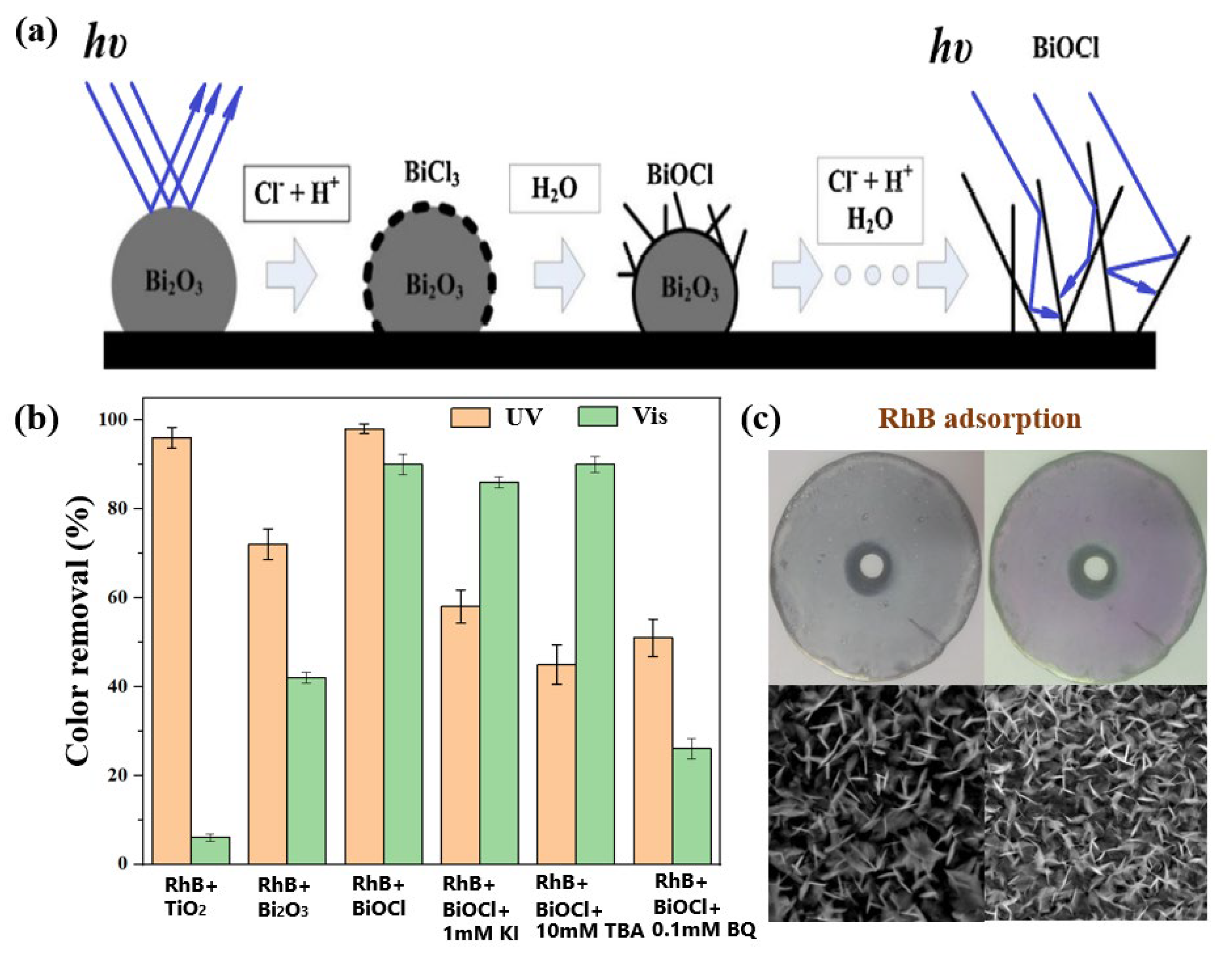
  82. Li, K.; Tang, Y.; Xu, Y.; Wang, Y.; Huo, Y.; Li, H.; Jia, J. A BiOCl film synthesis from Bi2O3 film and its UV and visible light photocatalytic activity. Appl. Catal. B Environ. 2013, 140–141, 179–188. [Google Scholar] [CrossRef]
  83. Li, K.; Zhang, H.; Tang, Y.; Ying, D.; Xu, Y.; Wang, Y.; Jia, J. Photocatalytic degradation and electricity generation in a rotating disk photoelectrochemical cell over hierarchical structured BiOBr film. Appl. Catal. B Environ. 2015, 164, 82–91. [Google Scholar] [CrossRef]
  84. Li, K.; Zhang, H.; He, Y.; Tang, T.; Ying, D.; Wang, Y.; Sun, T.; Jia, J. Novel wedge structured rotating disk photocatalytic reactor for post-treatment of actual textile wastewater. Chem. Eng. J. 2015, 268, 10–20. [Google Scholar] [CrossRef]
  85. Huang, S.; Li, L.; Zhu, N.; Lou, Z.; Liu, W.; Cheng, J.; Wang, H.; Luo, P.; Wang, H. Removal and recovery of chloride ions in concentrated leachate by Bi(III) containing oxides quantum dots/two-dimensional flakes. J. Hazard. Mater. 2020, 382, 121041. [Google Scholar] [CrossRef]
  86. Jiang, H.; Huang, S.; Lv, H.; Ge, D.; He, X.; Zhou, P.; Xiao, K.; Zhang, Y. Construction of bismuth-based porous carbon models by 3D printing technology for light-enhanced removal of chloride ions in wastewater. Water Res. 2022, 225, 119134. [Google Scholar] [CrossRef]
  87. Zhang, Y.; Ma, B.; Shao, S.; Shi, B.; Li, X.; Wang, C.; Chen, Y. Removal of chloride from waste acid using Bi2O3: Thermodynamics and dechlorination behavior. J. Water Process Eng. 2022, 49, 103048. [Google Scholar] [CrossRef]
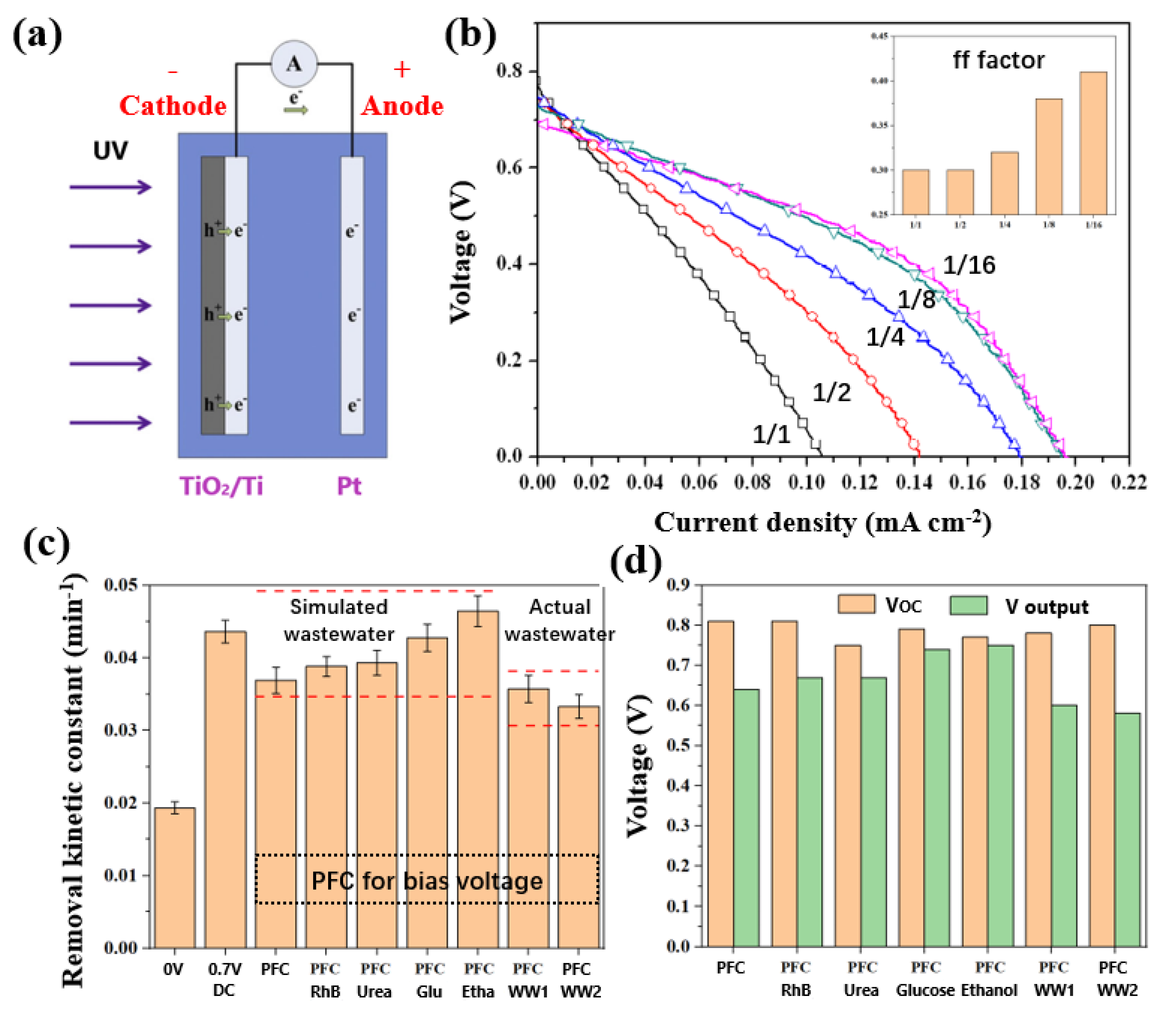
  88. Li, K.; Zhang, H.; Tang, T.; Xu, Y.; Ying, D.; Wang, Y.; Jia, J. Optimization and application of TiO2/Ti-Pt photo fuel cell (PFC) to effectively generate electricity and degrade organic pollutants simultaneously. Water Res. 2014, 62, 1–10. [Google Scholar] [CrossRef]
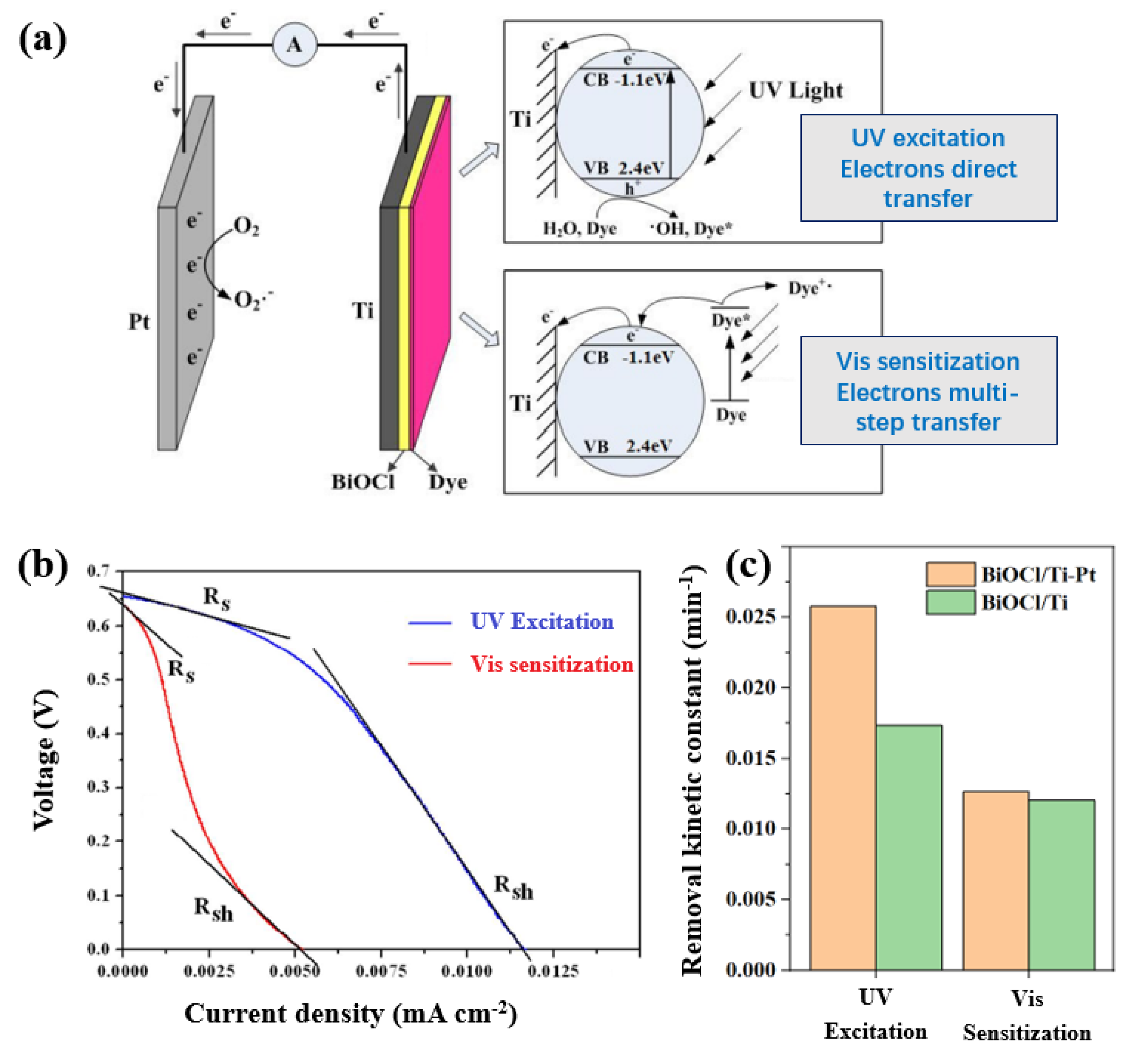
  89. Li, K.; Xu, Y.; He, Y.; Yang, C.; Wang, Y.; Jia, J. Photocatalytic Fuel Cell (PFC) and Dye Self-Photosensitization Photocatalytic Fuel Cell (DSPFC) with BiOCl/Ti Photoanode under UV and Visible Light Irradiation. Environ. Sci. Technol. 2013, 47, 3490–3497. [Google Scholar] [CrossRef]
  90. Zhang, L.; Liang, C.; Guo, H.; Niu, C.-G.; Zhao, X.-F.; Wen, X.-J.; Zeng, G.-M. Construction of a high-performance photocatalytic fuel cell (PFC) based on plasmonic silver modified Cr-BiOCl nanosheets for simultaneous electricity production and pollutant removal. Nanoscale 2019, 11, 6662–6676. [Google Scholar] [CrossRef]
  91. Zhang, L.; Niu, C.-G.; Zhao, X.-F.; Liang, C.; Guo, H.; Zeng, G.-M. Ultrathin BiOCl Single-Crystalline Nanosheets with Large Reactive Facets Area and High Electron Mobility Efficiency: A Superior Candidate for High-Performance Hye Self-Photosensitization Photocatalytic Fuel Cell. ACS Appl. Mater. Interfaces 2018, 10, 39723–39734. [Google Scholar] [CrossRef]
  92. Li, K.; Zhang, H.; Tang, T.; Tang, Y.; Wang, Y.; Jia, J. Facile electrochemical polymerization of polypyrrole film applied as cathode material in dual rotating disk photo fuel cell. J. Power Sources 2016, 324, 368–377. [Google Scholar] [CrossRef]
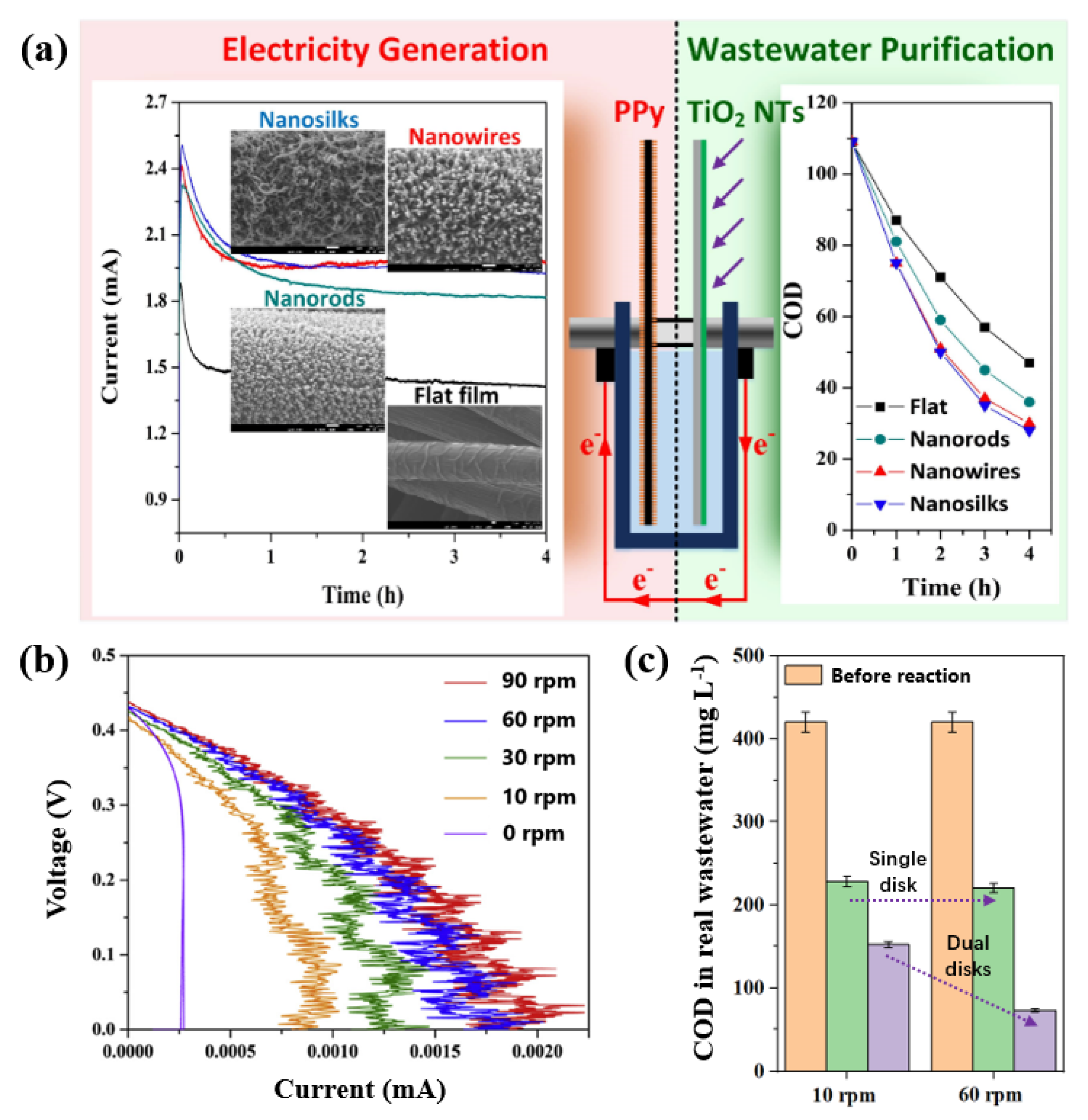
  93. Li, K.; Zhang, H.; Ma, Y.; Sun, T.; Jia, J. Nanostructured polypyrrole cathode based dual rotating disk photo fuel cell for textile wastewater purification and electricity generation. Electrochim. Acta 2019, 303, 329–340. [Google Scholar] [CrossRef]
  94. Wang, T.; Chutia, A.; Brett, D.J.L.; Shearing, P.R.; He, G.; Chai, G.; Parkin, I.P. Palladium alloys used as electrocatalysts for the oxygen reduction reaction. Energ. Environ. Sci. 2021, 14, 2639–3669. [Google Scholar] [CrossRef]
  95. Wu, H.; Feng, C.; Zhang, L.; Zhang, J.; Wilkinson, D.P. Non-noble Metal Electrocatalysts for the Hydrogen Evolution Reaction in Water Electrolysis. Electrochem. Energy R. 2021, 4, 473–507. [Google Scholar] [CrossRef]
  96. Zhang, X.; Wang, Y.; Liu, C.; Yu, Y.; Lu, S.; Zhang, B. Recent advances in non-noble metal electrocatalysts for nitrate reduction. Chem. Eng. J. 2021, 403, 126269. [Google Scholar] [CrossRef]
  97. Zhou, Y.; Abazari, R.; Chen, J.; Tahir, M.; Kumar, A.; Ikreedeegh, R.R.; Rani, E.; Singh, H.; Kirillov, A.M. Bimetallic metal-organic frameworks and MOF-derived composites: Recent progress on electro- and photoelectrocatalytic applications. Coordin. Chem. Rev. 2022, 451, 214264. [Google Scholar] [CrossRef]
  98. Wu, S.; Hu, Y.H. A comprehensive review on catalysts for electrocatalytic and photoelectrocatalytic degradation of antibiotics. Chem. Eng. J. 2021, 409, 127739. [Google Scholar] [CrossRef]
  99. Wang, B.; Biesold, G.M.; Zhang, M.; Lin, Z. Amorphous inorganic semiconductors for the development of solar cell, photoelectrocatalytic and photocatalytic applications. Chem. Soc. Rev. 2021, 50, 6914–6949. [Google Scholar] [CrossRef]
  100. Xu, Y.; He, Y.; Jia, J.; Zhong, D.; Wang, Y. Cu-TiO2/Ti Dual Rotating Disk Photocatalytic (PC) Reactor: Dual Electrode Degradation Facilitated by Spontaneous Electron Transfer. Environ. Sci. Technol. 2009, 43, 6289–6294. [Google Scholar] [CrossRef]
  101. Tang, T.; Li, K.; Ying, D.; Sun, T.; Wang, Y.; Jia, J. High efficient aqueous-film rotating disk photocatalytic fuel cell (RDPFC) with triple functions: Cogeneration of hydrogen and electricity with dye degradation. Int. J. Hydrogen Energ. 2014, 39, 10258–10266. [Google Scholar] [CrossRef]
  102. Tang, T.; Li, K.; Shen, Z.; Sun, T.; Wang, Y.; Jia, J. An appealing photo-powered multi-functional energy system for the poly-generation of hydrogen and electricity. J. Power Sources 2015, 294, 59–66. [Google Scholar] [CrossRef]
  103. Tang, T.; Li, K.; Shen, Z.; Sun, T.; Wang, Y.; Jia, J. Facile synthesis of polypyrrole functionalized nickel foam with catalytic activity comparable to Pt for the poly-generation of hydrogen and electricity. J. Power Sources 2016, 301, 54–61. [Google Scholar] [CrossRef]
  104. Li, J.; Listwan, A.; Liang, J.; Shi, F.; Li, K.; Jia, J. High proportion of 1 T phase MoS2 prepared by a simple solvothermal method for high-efficiency electroctalytic hydrogen evolution. Chem. Eng. J. 2021, 422, 130100. [Google Scholar] [CrossRef]
  105. Su, L.; Li, K.; Zhang, H.; Fan, M.; Ying, D.; Sun, T.; Wang, Y.; Jia, J. Electrochemical nitrate reduction by using a novel Co3O4/Ti cathode. Water Res. 2017, 120, 1–11. [Google Scholar] [CrossRef]
  106. Li, K.; Chen, C.; Bian, X.; Sun, T.; Jia, J. Electrolytic nitrate reduction using Co3O4 rod-like and sheet-like cathodes with the control of (220) facet exposure and Co2+/Co3+ ratio. Electrochim. Acta 2020, 362, 137121. [Google Scholar] [CrossRef]
  107. Chen, C.; Li, K.; Li, C.; Sun, T.; Jia, J. Combination of Pd-Cu Catalysis and Electrolytic H2 Evolution for Selective Nitrate Reduction Using Protonated Polypyrrole as a Cathode. Environ. Sci. Technol. 2019, 53, 13868–13877. [Google Scholar] [CrossRef]
  108. Bian, X.; Shi, F.; Li, J.; Liang, J.; Bao, C.; Zhang, H.; Jia, J.; Li, K. Highly selective electrocatalytic reduction of nitrate to nitrogen in a chloride ion-free system by promoting kinetic mass transfer of intermediate products in a novel Pd-Cu adsorption confined cathode. J. Environ. Manag. 2022, 324, 116405. [Google Scholar] [CrossRef]
  109. Shi, F.; Li, J.; Liang, J.; Bao, C.; Gu, J.-N.; Li, K.; Jia, J. Highly dispersed Pd-Cu bimetallic nanocatalyst based on γ-Al2O3 combined with electrocatalytic in-situ hydrogen production for nitrate hydroreduction. Chem. Eng. J. 2022, 434, 134748. [Google Scholar] [CrossRef]
  110. Chen, C.; Zhang, H.; Li, K.; Tang, Q.; Bian, X.; Gu, J.; Cao, Q.; Zhong, L.; Russell, C.K.; Fan, M.; et al. Cu+ based active sites of different oxides supported Pd-Cu catalysts and electrolytic in-situ H2 evolution for high-efficiency nitrate reduction reaction. J. Catal. 2020, 392, 231–243. [Google Scholar] [CrossRef]
Figure 1. (a) Light loss in a photocatalytic water treatment process and (b) the recombination of photogenerated electron and hole in a typical photocatalytic process.
Processes 11 00838 g001
Figure 2. (a) New demand for water treatment, bottlenecks in photocatalytic (PC) wastewater treatment and the corresponding solutions, including (b) light−harvesting excitation, (c) macro−scope transfer, and (d) multi−level utilization of photogenerated electrons.
Processes 11 00838 g002
Figure 3. Schematic diagrams of (a) immersed photocatalytic reactor, (b) inclined plate thin solution film photocatalytic reactor, and (c) rotating disk thin solution film photocatalytic reactor.
Processes 11 00838 g003
Figure 4. SEM images of (a) TiO2 nanoparticle film prepared by sol−gel and (b) TiO2 nanotube array film prepared by anodization, absolute quantity per m2 of RhB removal for 1 h obtained in (c) inclined plate reactor and (d) rotating disk reactor, the schematic diagrams of water in nanotubes in (e) inclined plate reactor, and (f) rotating disk reactor. (Reprinted/adapted with permission from Ref. [63]. 2012, ELSEVIER.
Processes 11 00838 g004
Figure 5. (a) Absolute quantity per m2 of RhB removal for 1 h obtained by planar structured, wedge structured, and pyramid structured photoanode and light reflectivity obtained by (b) wedge structured photoanode and (c) pyramid structured photoanode, with different bottom-to-height ratio. Reprinted/adapted with permission from Ref. [64]. 2011, American Chemical Society.
Processes 11 00838 g005
Figure 6. (a) Synthesis process of BiOCl and the light reflection on the surface of β-Bi2O3 thin film and BiOCl thin film, (b) RhB color removal obtained by different photoanode and the reactive oxygen species detection in the presence of different sacrificial agents, and (c) BiOCl-coated disk and BiOCl-coated disk with RhB adsorption and their corresponding SEM images. Reprinted/adapted with permission from Ref. [82]. 2013, ELSEVIER.
Processes 11 00838 g006
Figure 7. (a) Schematic diagram of TiO2/Ti−Pt PFC, (b) voltage−current curve of TiO2/Ti−Pt PFC with different anode area to cathode area ratio (inset is the corresponding ff factor), (c) RhB removal kinetic constants obtained in the presence of bias voltage and the bias voltage is applied by DC power and different PFC, and (d) open-circuit voltage (VOC) and the output voltage (V output) obtained by different PFCs. Reprinted/adapted with permission from Ref. [88]. 2014, ELSEVIER.
Processes 11 00838 g007
Figure 8. (a) Schematic diagram of BiOCl/Ti−Pt dye-sensitized PFC and the corresponding electron transfer path, (b) series resistance (Rs) and parallel resistance (Rsh) calculated under UV and visible light irradiation, and (c) RhB removal kinetic constant obtained in BiOCl/Ti system and BiOCl/Ti-Pt PFC system under UV and visible light irradiation. Reprinted/adapted with permission from Ref. [89]. 2013, American Chemical Society.
Processes 11 00838 g008
Figure 9. (a) Schematic diagram of dual rotating disk PFC with TiO2 nanotube arrays as photoanode, nanostructured PPy as cathode, and the corresponding short circuit current-time curves and COD removals in real wastewater (Reprinted/adapted with permission from Ref. [93]. 2019, ELSEVIER.), (b) voltage–current curves obtained at different rotating speed in a dual rotating disk PFC (Reprinted/adapted with permission from Ref. [92]. 2016, ELSEVIER.), and (c) effects of rotating speed on COD removal in a single rotating disk PFC and dual rotating disk PFC.
Processes 11 00838 g009
Figure 10. (a) Schematic diagram of TiO2/Ti-Pt black rotating disk PFC for H2 evolution (Reprinted/adapted with permission from Ref. [102]. 2015, ELSEVIER.), (b) SEM image of PPy cathode (Reprinted/adapted with permission from Ref. [102]. 2016, ELSEVIER.), and (c) H2 generate rates obtained by PPy cathode and Pt cathode in rotating disk PFC.
Processes 11 00838 g010
Figure 11. (a) Schematic diagram of H2 evolution in combination with Pd-Cu catalysis for nitrate removal in cathodic cell, (b) nitrate removal, and N2 selectivity in H2 evolution series Pd-Cu catalytic nitrate reduction system. (Reprinted/adapted with permission from Ref. [107]. 2019, American Chemical Society.)
Processes 11 00838 g011
Disclaimer/Publisher’s Note: The statements, opinions and data contained in all publications are solely those of the individual author(s) and contributor(s) and not of MDPI and/or the editor(s). MDPI and/or the editor(s) disclaim responsibility for any injury to people or property resulting from any ideas, methods, instructions or products referred to in the content.

