Article

Decision-Making Method for Mine Cable Insulation Monitoring and Grounding Fault Diagnosis

1
College of Electrical Engineering and Automation, Shandong University of Science and Technology, Qingdao 266590, China
2
School of Mechanical Electronic and Information Engineering, China University of Mining and Technology (Beijing), Beijing 100083, China
*
Author to whom correspondence should be addressed.
Processes 2023, 11(3), 795; https://doi.org/10.3390/pr11030795
Submission received: 10 February 2023 / Revised: 1 March 2023 / Accepted: 3 March 2023 / Published: 7 March 2023

Abstract

:
Real-time monitoring of the power cable state has tremendous significance for ensuring the safe and economic operation of mine power distribution systems. However, due to the harsh conditions of underground coal mines, it is difficult for the cable monitoring system operating in underground coal mines to carry out large-scale calculations to diagnose the grounding fault of the cable. Additionally, there are many types of cable grounding faults, such as single grounding fault and two-phase ground fault. Therefore, how to determine the type of grounding fault quickly through effective calculations and alarms to select the grounding cable is always a difficult task. In this study, to reduce the complexity of cable insulation state classification, we develop a novel classification method based on the decision tree algorithm. Concerning the zero-sequence network under different insulation conditions, the first calculation’s positive and negative values were generated to identify whether the cable insulation was symmetrical. Then, the insulation degradation phase is identified by the relationship between the three-phase voltage phase angle and the current difference variation between the beginning and end of the line. By substituting the correlation quantities collected by a wide-area synchronous measurement system into different equations, the whole grid’s decision tree was constructed in different insulation states. Then, the insulation state of each line was evaluated according to the conductance value. The effectiveness of the proposed method was verified using a 35/6 kV mine power distribution system model based on the MATLAB/Simulink platform. The test results illustrate that the method can accurately diagnose the power cable insulation state based on the decision tree of whether the grid three-phase loads operate in an ungrounded mode or not.

1. Introduction

Power cables are widely used in coal mine power distribution systems. However, due to the narrow space of the coal mine, the mine cables are mostly laid along the roadways, and they are vulnerable to external forces such as squeezing and collision, which damages the insulation of the cables and causes a cable grounding fault. When the cable insulation deteriorates, it may cause an electric shock or cable firing. This situation is very dangerous in coal mines and may cause more serious coal mine accidents. Therefore, it is significant to perform insulation monitoring on the mine cables in real-time to detect and eliminate faults in time [1,2,3,4,5,6].
The existing online cable insulation monitoring methods include the partial discharge, DC superposition, ground line current, and dielectric loss methods [1,6,7,8,9,10,11,12,13,14,15,16,17]. The partial discharge signal is difficult to measure and is not suitable for harsh conditions [9,10]. The DC superposition method requires an additional source and cannot measure the distributed capacitance of the cable to the ground [11,12]. The grounding current and dielectric loss methods are inaccurate because they use empirical values to evaluate the cable insulation state that proposes that two branches be selected for grounding experiments. The insulation parameters of all branches can be calculated by collecting the zero-sequence current of each branch and the zero-sequence voltage of the bus. However, this method does not consider the insulation asymmetry which may exist in the cable itself [13,14,15,16,17]. In order to make up for the shortcomings of previous methods, many scholars have proposed some new methods for cable insulation diagnosis in recent years. For example, in the literature [18], low-frequency signals are coupled into cables to monitor the insulation of cables, the leakage current and voltage data of cables are extracted, and the insulation impedance is calculated by the fast Fourier algorithm. Ref. [19] proposed a monitoring scheme method based on leakage current measurements at a selected monitoring frequency, and an aging feature extraction method based on principal component analysis (PCA), which can estimate the severity of insulation aging. With the development of computer technology, more and more scholars use data-driven machine learning algorithms in cable fault diagnosis [20,21,22,23,24,25,26,27,28,29,30,31]. Ref. [20] proposed a cable fault diagnosis knowledge base based on machine learning. By collecting the wavelet entropy of cable fault signals, the noise change relationship of the fault signal is reflected, and the noise energy threshold of the cable fault signal is determined. The fuzzy decision matrix of the cable fault diagnosis knowledge base is established by machine learning. Ref. [21] established fault criteria and a database by simultaneously measuring two current maps in coaxial cables, and detected cable faults by analyzing changes in characteristic parameters of the maps. Ref. [22] introduced a fault severity prediction method based on a one-dimensional convolution residual network without prior cable knowledge. By correlating the channel transfer function (CTF) with the fault information, a pilot-based deep learning network that can extract fault features more accurately emerged.
However, the above methods are aimed at the fault diagnosis of cables in the common power grid. Compared with the ordinary power grid, underground coal mine power grids have many particularities. The fault diagnosis method of coal mine cables cannot follow the fault diagnosis method of common cables. Due to the harsh working environment of downhole equipment, large-scale data communication cannot be realized. Underground mine cable monitoring systems, generally perform in situ monitoring and directly calculate diagnoses and alarms. Generally, there are only small current grounding monitoring systems in cable monitoring systems. The data types and fault samples obtained are very few. In this environment, DSP is generally used as the computing core of cable fault diagnosis equipment [23,24,25]. Therefore, it is difficult to use machine learning algorithms for fault diagnoses of underground coal mine cables. Additionally, for the coal mine power grid, the most urgent need is to quickly diagnose the grounding fault of the cable and quickly cut off the fault, so as to prevent accidents. How to judge the type of grounding fault quickly through effective calculations under such harsh conditions, and to select the grounding cable is a difficult point at present. In addition, the above method of judging the cable insulation state is by one single calculation model. For different types of insulation deterioration, the relationship between the zero-sequence component of cable and insulation parameters is different, that is, the calculation model of cable insulation state is different. Only one model as the basis for the diagnosis of cable insulation status cannot accurately reflect the real insulation level of the cable, and there is the possibility of misjudgments.
In view of the problems above, a new method for cable grounding fault monitoring is proposed. First, by modeling the zero-sequence network of cables with single-phase and two-phase insulation degradation, a method applicable for pattern recognition analysis is established. Based on this, a diagnostic decision tree based on the zero-sequence components and insulation parameters to diagnose the cable insulation state is proposed, which can judge multiple insulation faults under complex conditions. Finally, a simulation model is built on the MATLAB/Simulink platform to verify the effectiveness of the proposed method. The simulation results illustrate that our method can accurately diagnose the power cable insulation state.
The rest of this paper is organized as follows. In Section 2, according to the different types of cable insulation deterioration, the criterion model of insulation state diagnosis is established, and the principle of cable insulation diagnosis is described. In Section 3, the construction method of the decision tree is introduced. In Section 4, the effectiveness of the proposed method is verified using a simulation.

2. Materials and Methods

The equivalent operation circuit of the mine power grid is shown in Figure 1a. If the zero-sequence voltage U 0 appears due to parameter asymmetry, the voltage at the system’s neutral point is equal to the zero-sequence voltage. The transformer’s neutral point adopts the ineffective grounding method (not grounded or grounded via the arc suppression coil), and the neutral point of the three-phase load for each branch is grounded.
In Figure 1a, Z i 1 , Z i 2 , Z i 3 , ( i = 1 , 2 . n ) are the arc suppression coil reactances; G i A , G i B , G i C , ( i = 1 , 2 . n ) are the three phase insulation conductances for each branch; C i A , C i B , C i C , ( i = 1 , 2 . n ) are the three phase distributed capacitances for each branch; I 0 i ( i = 1 , 2 . n ) is the zero-sequence current of each branch; Z l i ( i = 1 , 2 . n ) is the impedance of load for each branch; and I l 0 i ( i = 1 , 2 . n ) is the zero-sequence current flowing through the load into the earth. Figure 1b shows the zero-sequence circuit of the branch with symmetrical insulation parameters.
According to Kirchhoff’s Current Law, the zero-sequence voltage and current of a three-phase symmetrical line satisfy
I ˙ 0 i I ˙ l 0 i = Y i U ˙ 0 = G i U ˙ 0 + j ω C i U ˙ 0
where, Y i = Y a + Y b + Y c , Y a = G a + j w C a , Y b = G b + j w C b , and Y c = G c + j w C c , Y a = Y b = Y c .
In the case of single-phase and two-phase deterioration of cable insulation, the equivalent circuit model of the degraded insulation line is different because of the difference of the zero-sequence voltage value in the zero-sequence network. In order to comprehensively analyze the cable insulation deterioration, the characteristics of the two types of insulation degradation will be analyzed one by one.

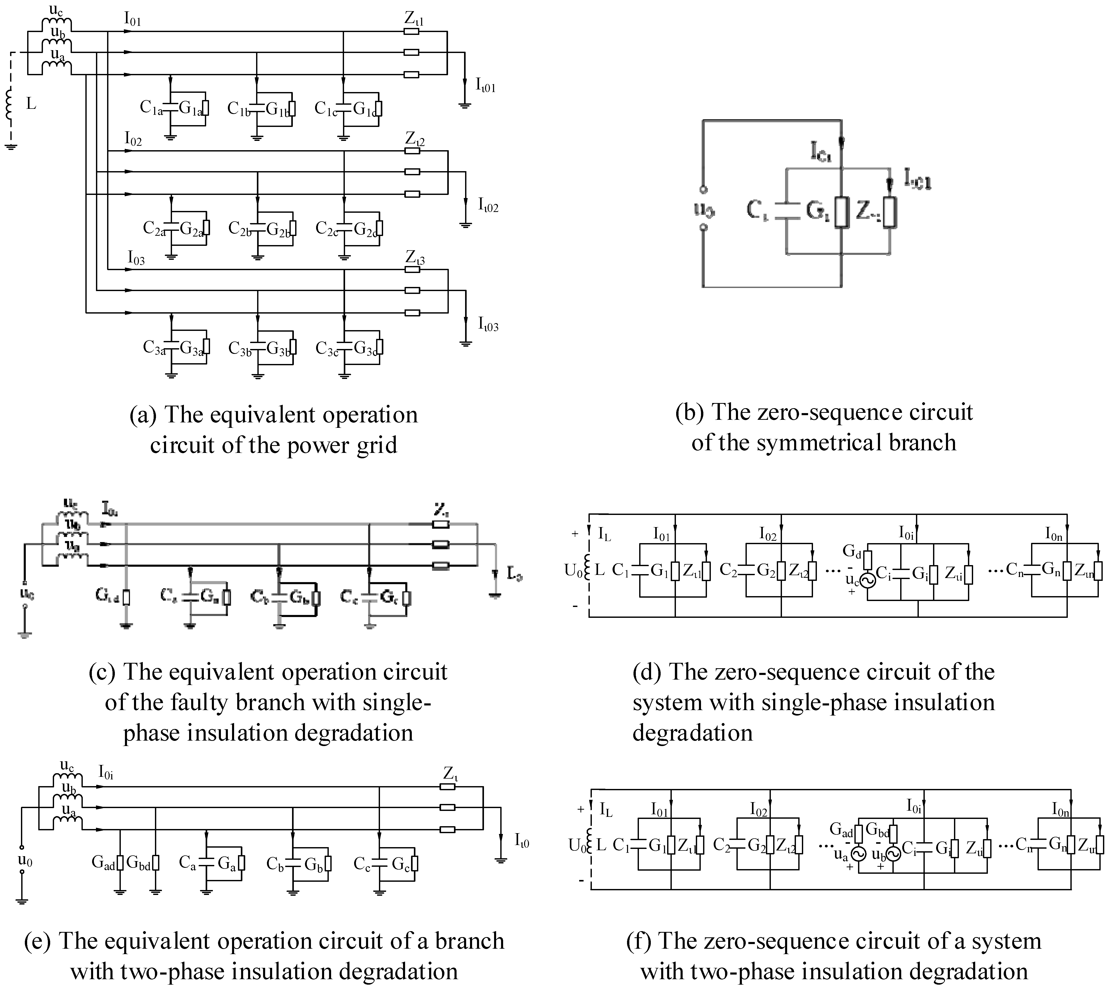
2.1. Zero-Sequence Network of a Power System under Single-Phase Insulation Degradation

When single-phase insulation degradation occurs in the system, it is equivalent to adding a conductance G d between the faulty branch and the ground. Assuming that the faulty phase is phase C, its equivalent branch operation circuit is shown in Figure 1c. It can be seen from Figure 1c that zero sequence current appears in phase C. Additionally, the zero-sequence current of the faulty branch satisfies Equation (2).
I 0 i - I l 0 i = ( U 0 + U a ) Y a + ( U b + U 0 ) Y b + ( U c + U 0 ) ( Y c + G d )
Since the three-phase voltage meets equation U a + U b + U c = 0 . Then, Equation (2) can be simplified as
I 0 i - I l 0 i = U 0 Y i + ( U c + U 0 ) G d
Therefore, the zero-sequence circuit of a system with single-phase insulation degradation is shown in Figure 1d.
When the neutral point is not grounded, the relationship between the zero-sequence and phase voltages is
U ˙ 0 = U ˙ c G d G + j ( ω C 1 ω L ) + G d   = U ˙ c G d ( G + G d ) 2 + ( ω C ) 2 e j ( π + θ 1 )
θ 1 = t a n 1 ( ω C G G d )
When the neutral point is grounded via the arc suppression coil, the relationship between the zero-sequence and phase voltages is
U ˙ 0 = U ˙ c G d G + j ( ω C 1 ω L ) + G d   = U ˙ c G d ( G + G d ) 2 + ( ω C ) 2 e j ( π + θ 2 )
θ 2 = t a n 1 ( ω C 1 ω L G + G d )
It can be seen from the above analysis that the grounding mode affects the zero-sequence voltage of the system when the single-phase insulation drops, but it does not affect the relationship between the zero-sequence component and the insulation parameters.

2.2. Zero-Sequence Network of a Power System under Two-Phase Insulation Degradation—Abbreviations and Acronyms

If two-phase insulation degradation occurs in the power system, the three-phase insulation conductance of the cable is not equal. Additionally, the zero-sequence network of the system is constant, and the asymmetry caused by the decrease of insulation causes the system to generate zero-sequence voltage. The equivalent operation circuit of the faulty branch is shown in Figure 1e.
According to Kirchhoff’s current law, the zero-sequence current of the faulty branch satisfies Equation (8).
I ˙ 0 i I ˙ l 0 i = Y a ( U ˙ 0 + U ˙ a ) + ( G d b + Y b ) ( U ˙ 0 + U ˙ b ) + ( G d c + Y c ) ( U ˙ 0 + U ˙ c )   = Y i U ˙ 0 + G d b ( U ˙ 0 + U ˙ b ) + G d c ( U ˙ 0 + U ˙ c )
The zero-sequence circuit of the whole system is shown in Figure 1f, the faulty branch is branch i , and the insulation of other branches is normal.
When the neutral point is not grounded, the relationship between the zero-sequence and the phase voltages is
U ˙ 0 = U ˙ b G d b + U ˙ c G d c G + j ω C + G b d + G d c   = U ˙ b G d b + U ˙ c G d c ( G + G d b + G d c ) 2 + ( ω G ) 2 e j ( π + θ 1 )
θ 1 = t a n 1 ( ω C G + G d b + G d c )
When the neutral point is grounded via the arc suppression coil, the relationship between the zero-sequence and phase voltages is
U ˙ 0 = U ˙ a G d G + j ( ω C 1 ω L ) + G d b + G d c   = U ˙ a G d ( G + G d b + G d c ) 2 + ( ω C ) 2 e j ( π + θ 2 )
θ 2 = t a n 1 ( ω C 1 ω L G + G d b + G d c )
It can be seen from the above analysis that the two grounding methods do not affect the relationship between the zero-sequence component of the branch and the insulation parameters. Additionally, the grounding mode affects the zero-sequence voltage of the system when the two-phase insulation drops, but it does not affect the relationship between the zero-sequence component and insulation parameters. In addition, there is three-phase cable insulation degradation. The three-phase insulation parameters of cable insulation are equal when the three-phase insulation degrades symmetrically. However, the probability of three-phase insulation degrading symmetrically in the power supply system is very small. Therefore, it is not discussed in this article.
According to the relationship between insulation parameters and the zero-sequence component, cable insulation degradation can be divided into symmetric insulation degradation and asymmetric insulation degradation. Additionally, the insulation asymmetry state can be further divided into single-phase and two-phase insulation degradation. It can be seen from Equation (4) to Equation (12) that the voltage and phase angle corresponding to different insulation faults are different. Therefore, the diagnosis of different types of cable insulation faults can be realized by monitoring the voltage and phase angle.
For the coal mine cable monitoring system, the real-time monitoring data are analyzed by a separate model for each type of fault, which not only increases the amount of calculations, but also affects the time of the system to judge the fault [23,24,31]. Therefore, we propose a classification method from top to bottom using a decision tree to solve the cable grounding fault classification problem quickly and effectively. There are different formulas, which fit different modes, to calculate insulation parameters accurately. The fault is issued when the computed value of the insulation parameter is less than the setting value. In this way, the system only needs to carry out a group of logical judgment processes through the decision tree model, and can quickly find the fault cable. Therefore, the diagnosis system identifies the fault type and output insulation parameters online.

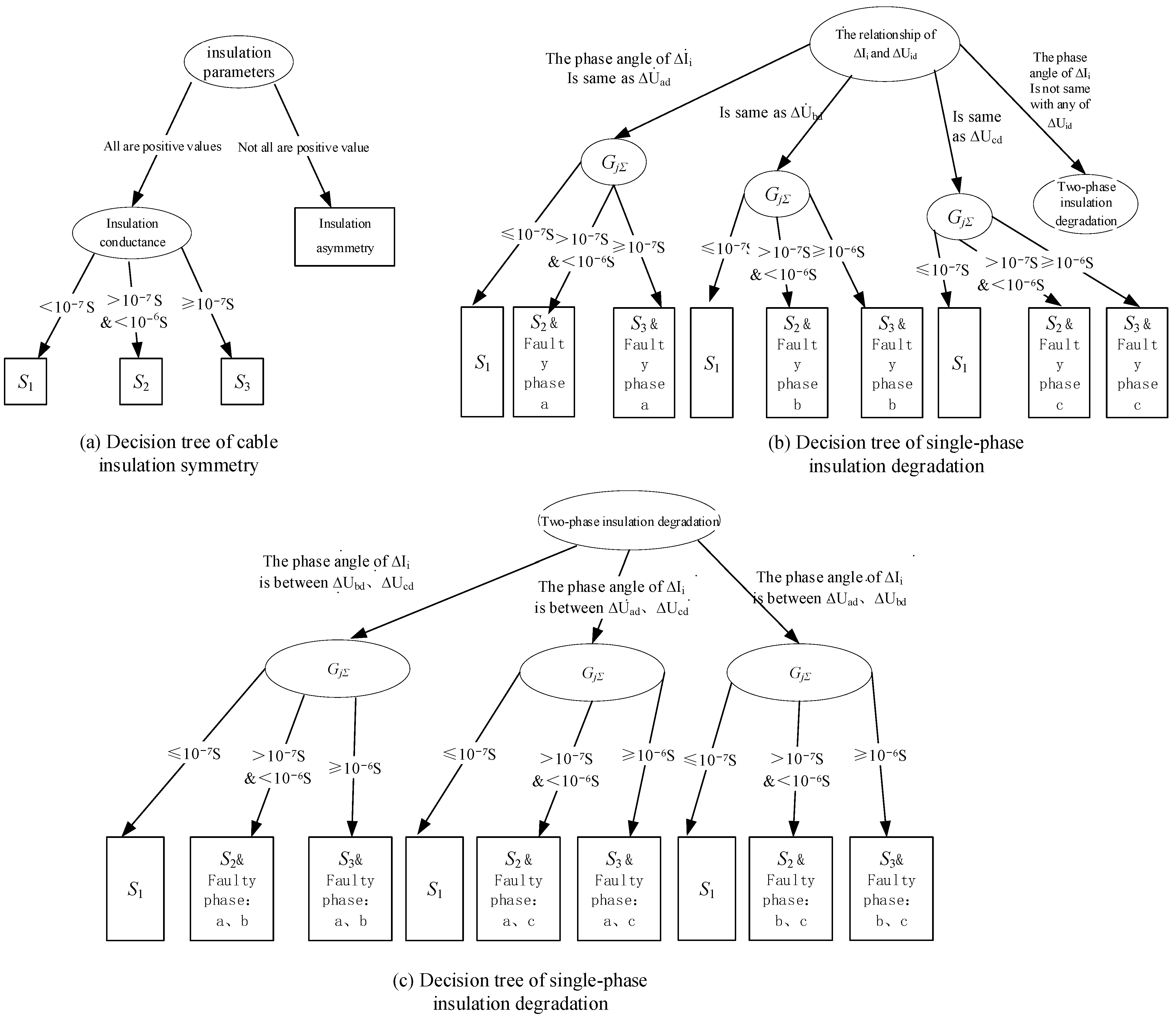
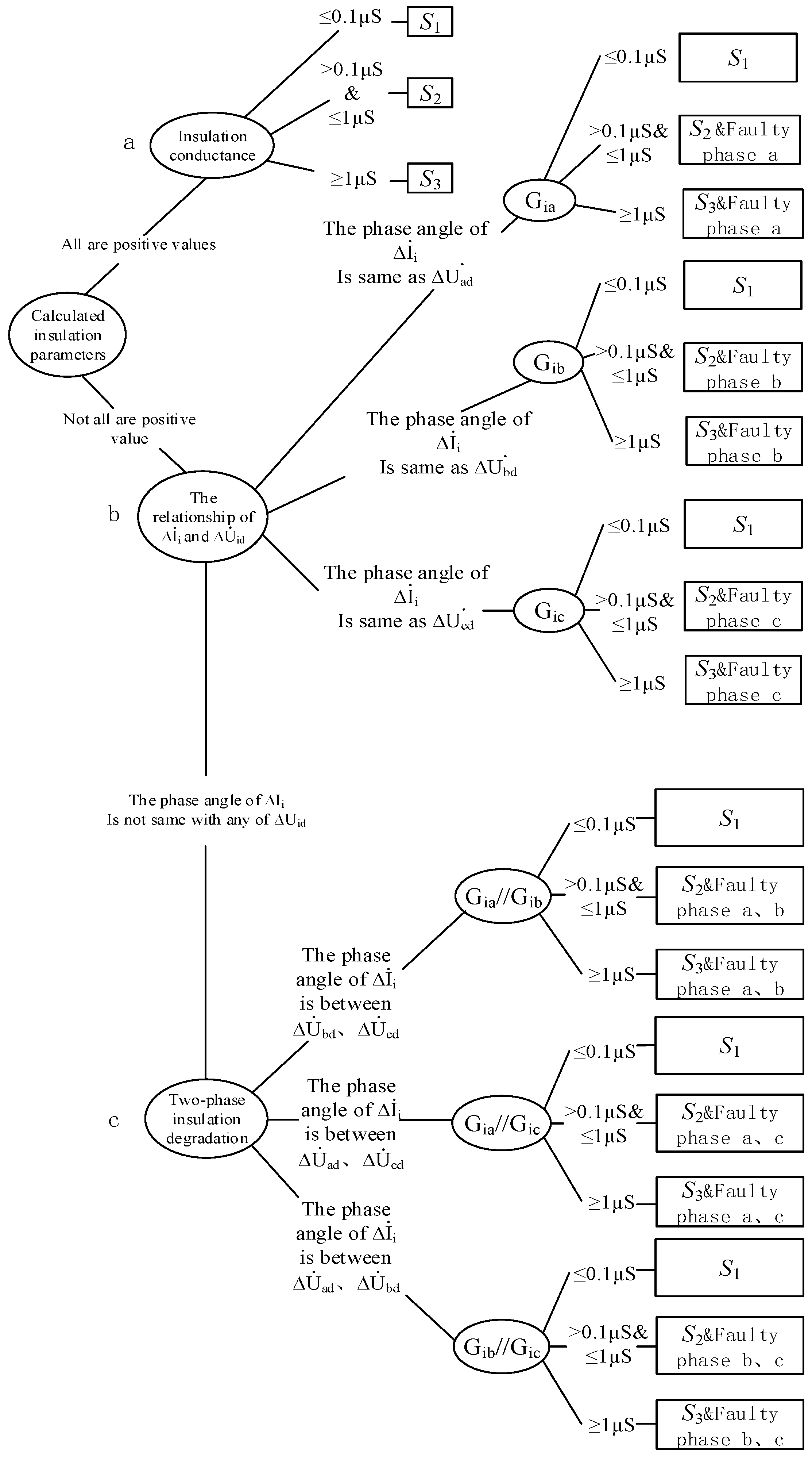
2.3. The Criterion for Insulation State Diagnosis

The total insulation of the cable is the parallel resistance of the three-phase insulation resistance. The cable insulation state can be roughly divided into three categories, namely, good, moderate attention, and close attention, whether in operation or not. According to the 6 kV cable insulation evaluation criteria, the classification table is shown in Table 1.

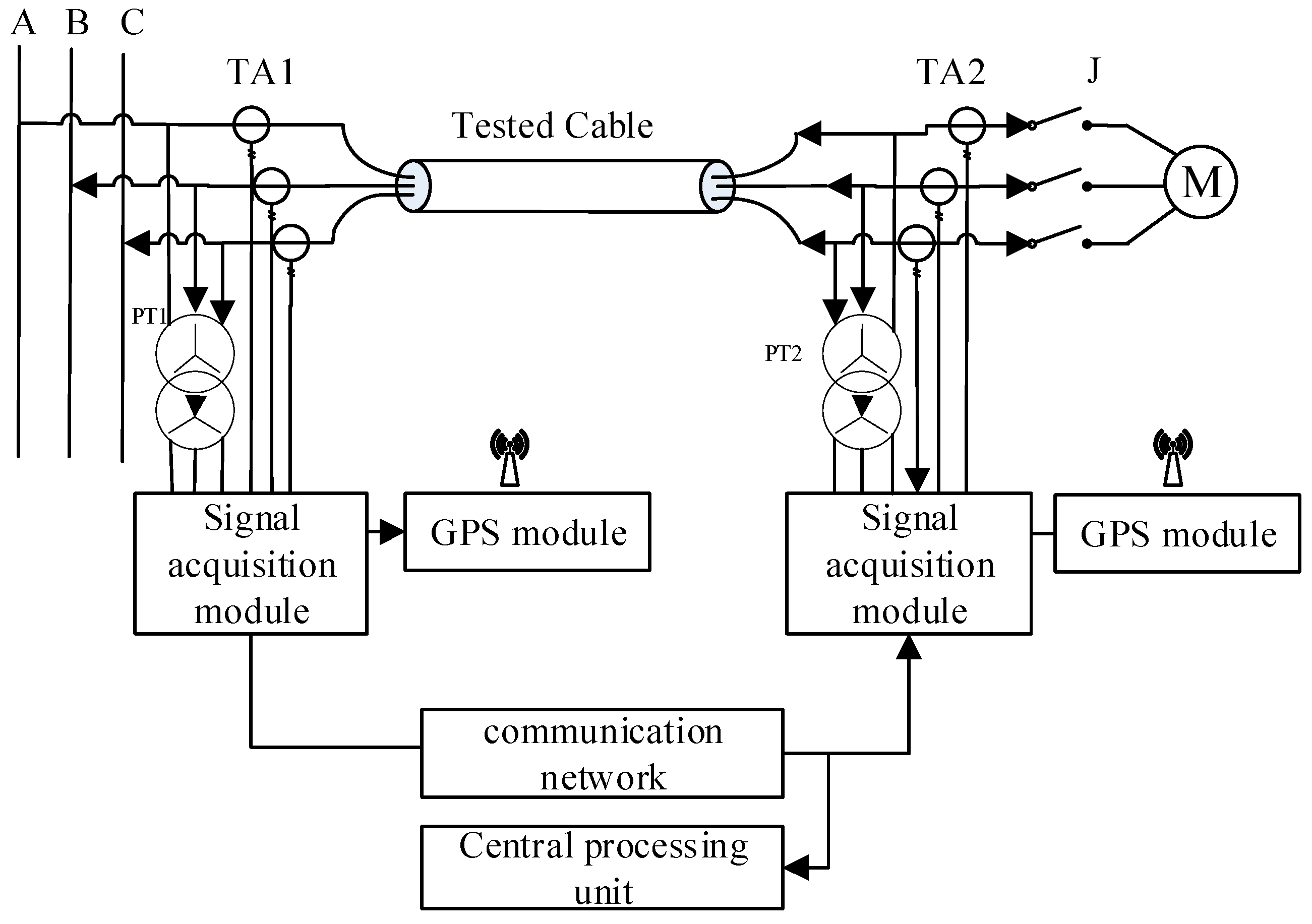
2.4. Cable Insulation Diagnosis Monitoring System

The diagnosis and monitoring system is shown in Figure 2. It consists of four parts: a GPS unit, phasor measurement unit, communication unit, and control center [22,23,24,25,26]. The GPS unit provides a synchronous timing signal for the entire network, ensuring the data are synchronized with no space limit. GPS equipment in the mine transmits signals to the surface through optical fibers or an underground communication network, and then synchronizes the time through the surface GPS system and satellite system. This monitoring method has been proposed in Refs. [6,23,24]. The phasor measurement unit is installed in the field dispersedly, and the zero-sequence voltage of the bus, the zero-sequence current, the phase to ground voltage, and other useful data are synchronously collected. The measuring units of each branch are shown in Figure 2. During the phasor measurement process, the data sampling pulse is controlled by the GPS synchronous timing pulse signal [24,25,26,27,28]. The communication network transmits data to the control center for online analysis, then the control center calculates insulation parameters and generates control strategies for protection online.

2.5. Cable Insulation Diagnosis Method Base on Decision Tree

Cable insulation status can be divided into four types: insulation is normal, single-phase insulation degradation, two-phase insulation degradation, symmetrical three-phase insulation degradation. Cable grounding faults caused by the four types of cable insulation state are also divided into four types: normal state, single-phase grounding fault, two-phase grounding fault, and already three-phase grounding fault [1]. Through the previous analysis, it can be seen that the voltage and phase angle relationships of the four states are different, and it is an effective method to use classification algorithms to diagnose faults for this difference. The states of these four kinds of insulation are completely different, and the classification is complicated. In order to solve the complex classification problem of cable insulation quickly and effectively, a decision tree method is proposed to realize hierarchical classification from top to bottom.
Assuming all the lines’ insulation parameters are symmetrical, the differential equation can be obtained, by
i 0 i - i 0 l i = C i d u 0 d t + G i u 0
The zero-sequence voltage of the bus, the zero-sequence current at the beginning, and the zero-sequence current at the end of each branch are synchronously acquired. The derivative of the zero-sequence voltage can be calculated by
d u 0 d t m = u 0 ( m + 1 ) u 0 ( m 1 ) 2 Δ t
where the n is set as the sample data number and Δ t is set as the sample interval. Setting the equations by selecting sampled data at equal intervals:
( d u 0 d t ( 1 ) u 0 ( 1 ) d u 0 d t ( 2 ) u 0 ( 2 ) d u 0 d t ( m ) u 0 ( m ) ) · ( C 1 C 2 C n G 1 G 2 G n ) = ( i 01 ( 1 ) i 02 ( 1 ) i 0 n ( 1 ) i 01 ( 2 ) i 02 ( 2 ) i 0 n ( 2 ) i 01 ( m ) i 02 ( m ) i 0 n ( m ) )
The m is the number of the selected data in the equation. If one of the insulation parameters calculated by Equation (15) has a negative value, the insulation parameter of this line is asymmetrical. Conversely, it can be derived from Equations (1) and (2) that the change in the difference of the zero-sequence current Δ I ˙ i before and after single-phase insulation degradation is
Δ I ˙ i = G d ( U ˙ c + U ˙ 0 ) + Y i ( U ˙ 0 U ˙ 0 )
The change in zero-sequence voltage is insignificant before and after the insulation degradation, so the zero-sequence current change can be ignored, and formula (17) turns into
Δ I ˙ i G d ( U ˙ c + U ˙ 0 ) = G d U ˙ c d
U ˙ c d is the relative voltage to the ground of phase C. It can be derived from Equation (18) such that the phase angle of the Δ I ˙ i of each branch is the same as the phase angle of the faulty phase’s relative voltage to the ground. Therefore, this relationship can be used as a criterion to identify single-phase insulation degradation. When the zero-sequence current is at the beginning of the line, it can be judged that single-phase insulation degradation occurs on a particular line when the phase angle of the current difference variation is the same as one of the three relative phase voltages to the ground.
Simultaneously, a faulty branch with single-phase insulation degradation satisfies Equation (3), so the differential equation can be derived.
i 0 i i 0 l i = C i d u 0 d t + G i u 0 + G d u c d
Substitute m sets of data collected by the wide-area synchronous measurement system into the equations. Additionally, the branch insulation degradation degree could be evaluated by comparing the calculated insulation parameters and the setting value. The decision subtree is shown in Figure 3b.
When the two-phase insulation deteriorates (set to b and c phases), it can be derived from Equations (2) and (4) such that the variation of the zero-sequence current at the beginning and end of the branch is
Δ I ˙ i = G d b ( U ˙ b + U ˙ 0 ) + G d c ( U ˙ c + U ˙ 0 ) + Y i ( U ˙ 0 U ˙ 0 )   G d b U ˙ b d + G d c U ˙ cd
Therefore, this characteristic can be used as a criterion when the phase angle of Δ I ˙ i of a certain branch is between the phase angle of the two phases’ relative voltage to the ground. The monitoring will judge that this branch has two-phase insulation degradation and determine the faulty phase.
The degree of insulation degradation can be determined based on the calculated insulation parameters according to the equation. The decision subtree is shown in Figure 4c. The complete decision tree for the whole grid is shown in Figure 3c.
It should be noted that if the three-phase loads of the grid are operated in an ungrounded mode, the equation i 0 = i 0 i i 0 l should be substituted by i 0 = i 0 i , because there will not be a current path for the zero-sequence current at the end of the line. Additionally, only the zero-sequence current at the head of each branch should be collected. Suppose a branch is connected to a substation of a lower voltage grade. In that case, the i 0 should be the amount of current difference between branch zero-sequence current and zero-sequence current for all lines belonging to the substation.
The primary condition for subtree synthesis is the existence of the same properties. In the above three subtrees, single-phase insulation degradation and two-phase insulation degradation are both types of insulation asymmetry. The method to judge the deterioration of cable insulation is the phase relationship between the zero-sequence current conversion and the relative ground voltage. Therefore, three subtrees can be combined into one decision tree. The complete decision tree is shown in Figure 4.

3. Simulation Verification and Results

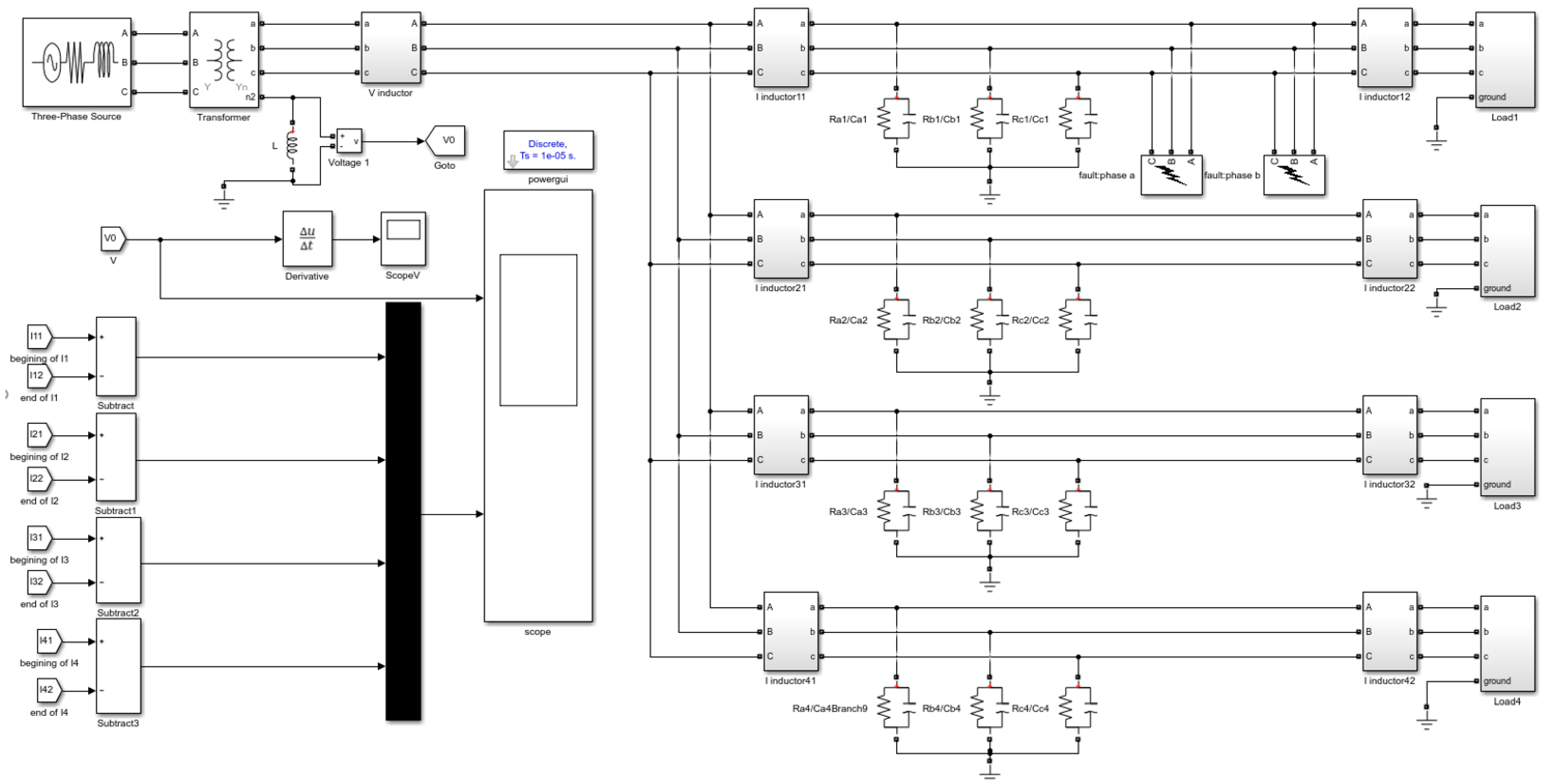
3.1. Construction of the Simulation Model

To verify the effectiveness of the insulation monitoring algorithm based on the decision tree, the 35/10 kV single radiating power supply system shown in Figure 5 was built on the MATLAB/Simulink platform. This is a very typical power supply network model in coal mines [1,6,24]. Table 2 shows the setting parameters of the insulation and load power of each branch. It can be seen from Section 2.3 that the two grounding methods do not affect the relationship between the zero-sequence component of the branch and the insulation parameters, so some types of the neutral points are grounded by the arc suppression coil (the overshoot compensation coefficient of the arc suppression coil is 1.5), and some types of neutral points are not grounded. Since the load imbalance does not affect the method, the model sets three-phase balanced loads for four branches. According to the cable insulation evaluation standard of 10 kV, when the calculated branch insulation conductance value is greater than 0.1 μS, the branch is judged to have slightly deteriorated insulation, and when the calculated branch conductance value is equal to or greater than 1 μS, the branch is judged to have seriously deteriorated insulation.

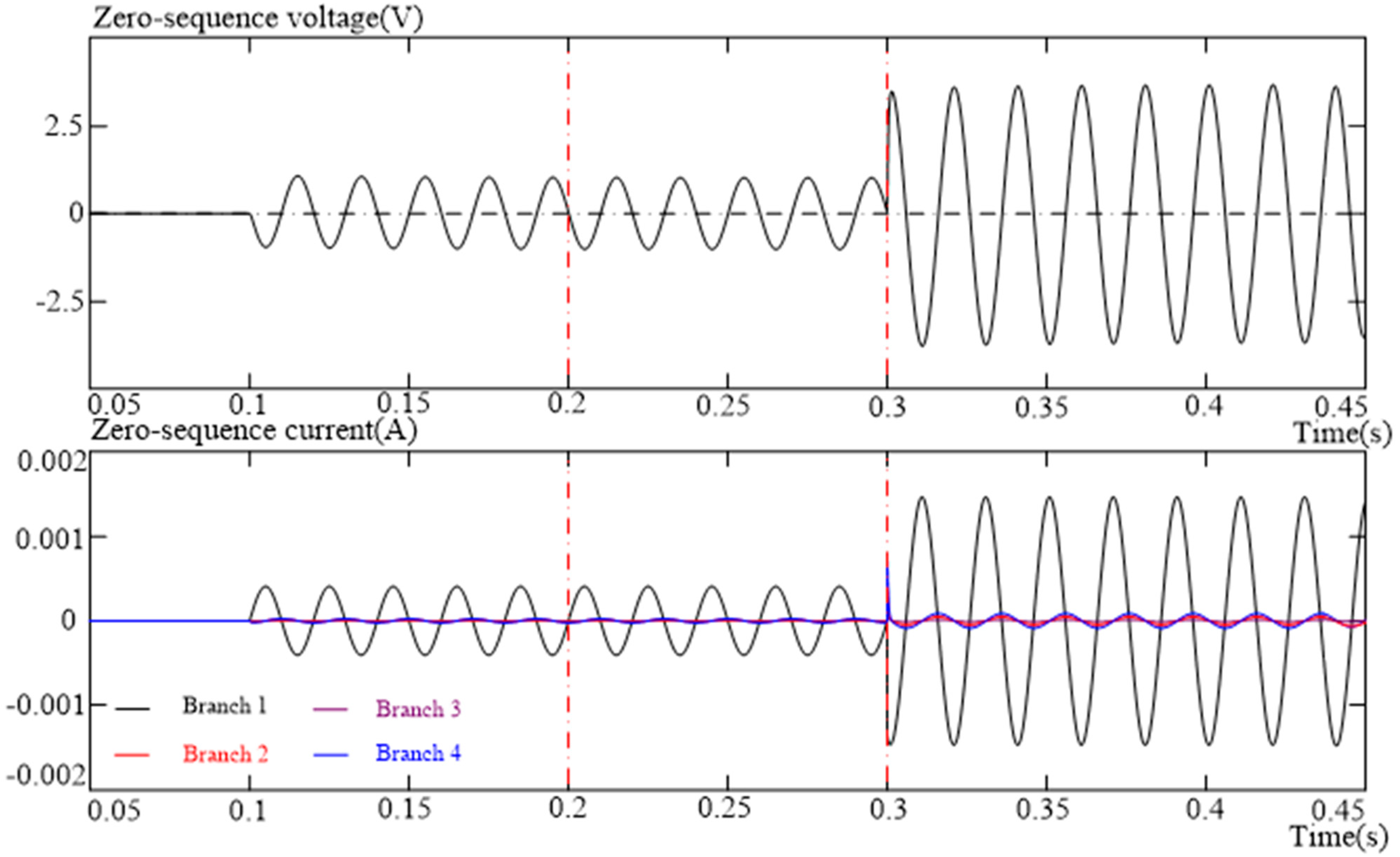
3.2. Analysis of Neutral Grounding System Simulation Results

The simulation time is 0.5 s, and four branches were selected as fault branches in turn. At 0.1 s, single-phase insulation degradation occurs on the faulty branch, and the phase a insulation conductance decreases to 0.5 μS. At 0.3 s, two-phase insulation degradation occurs on the faulty branch, and the phase b insulation of the faulty branch is reduced to 2 μS while the phase an insulation is maintained at 0.5 μS. Other branches have normal insulation during the simulation. While branch 1 is the faulty branch and the neutral point are grounded by the arc suppression coil, the waveform diagrams of the system zero-sequence voltage and the zero-sequence current difference between the beginning and the end of each branch are shown in Figure 6.
The insulation parameters of each branch calculated by Equation (18) are shown in Table 3. Among them, the insulation parameter of branch 1 has a negative value, and the insulation parameters of the other lines are all positive values, so it can be judged that the insulation asymmetry fault occurred on branch 1.
The system does not have zero-sequence voltage and current until 0.1 s, and because the system capacitance is continuously charged and discharged, the zero-sequence voltage has a DC component. At 0.3 s, the zero-sequence current of branch 1 has an obvious variation. The characteristics of the waveform diagrams prove that the simulation model is correct.
The calculated phase angle of I ˙ i and the U ˙ a d , U ˙ b d , U ˙ c d of branch 1 around the time when the single-phase insulation degradation occurred are shown in Table 4.
The calculations show that the phase angle of the current difference rate between the beginning and end of branch 1 is the same as the phase angle of phase c relative voltage to ground. Therefore, it can be determined that the faulty phase is phase c of branch 1. Substituting the sampled value of branch 1 into Equation (17), the results and calculation error are shown in Table 5.
It can be judged that the insulation of the branch 1 phase a is lower, and the calculation error is smaller. At 0.3 s, the insulation parameters of each line calculated by Equation (13) are shown in Table 6.
The insulation parameters of branch 1 have negative values, and the insulation parameters of branch 1 to branch 4 have positive values. It can be judged that insulation asymmetry occurred on branch 1. Therefore, it can be judged that branch 1 has asymmetrical insulation. The phase angle of Δ I ˙ 1 and the relative voltage to ground of the three phases are shown in Table 7.
The Δ I ˙ 1 phase angle is between the phase angles of the phase a and phase b relative voltage to the ground, so it can be judged that phases a and b are faulty. The calculation results by substituting the sampled value into Equation (18) are shown in Table 8.
The calculation results show that the insulation of the line is seriously degraded. At this time, the alarm signal of the monitoring system should be issued, and the cable should be replaced. The simulation results of the other branches when they are selected as the faulty branch in turn are shown in Table 9.
The above simulation shows that the insulation diagnosis for each branch corresponds to the simulation settings, and the insulation parameter calculation error is small. All simulation results proved that this method can quickly identify the faulty cable and fault phase without a lot of calculations.

4. Conclusions

A calculation method of cable insulation state based on a decision tree is proposed in this paper. This method judges the line with asymmetrical insulation degradation according to the negative calculated insulation parameters, and it identifies the phase with asymmetrical insulation according to phase angle relationships. Different insulation types correspond to different calculation formulas for the insulation parameters, so the accuracy of the calculated results could be guaranteed. The simulation results show the advantages of this method: it can correctly recognize the insulation type and realize the fault line and phase selection with small calculation errors for the line insulation parameters. However, this paper does not consider the error that may occur when synchronously acquiring zero-sequence current and voltage, as well as the error that a signal conditioning circuit may cause. How to improve the method for gathering and processing signals to reduce errors will be the emphasis of further research to optimize this method. In addition, with the development of computer technology and communication technology, it becomes feasible to apply machine learning algorithms to underground coal mine cable monitoring. Our future research direction will focus on this point.

Author Contributions

C.F. proposed the research topic, designed the model, performed the simulations, and analyzed the data. P.Y. was responsible for guidance, proposing the research topic, giving constructive suggestions, and revising the paper. Y.S. performed the simulations and analyzed the data. J.L. improved the manuscript and corrected the spelling and any grammar mistakes. X.Z. and C.S. collected information and organized and revised the manuscript. All authors have read and agreed to the published version of the manuscript.

Funding

This research received no external funding.

Institutional Review Board Statement

Not applicable.

Informed Consent Statement

Not applicable.

Data Availability Statement

The original contributions presented in the study are included in the article. Further inquiries can be directed to the corresponding author.

Conflicts of Interest

The authors have no conflict of interest to declare. The authors do not have any personal circumstances or interest that may be perceived as inappropriately influencing the representation or interpretation of the reported research results.

References

  1. Zhao, Y.; Li, J.; Wu, L.; Wang, Y. High-voltage cable insulation online monitoring in coal mine based on pattern recognition. In Proceedings of the International Conference on Advances in Materials, Machinery, Electronics, AMME, Tianjin, China, 10–11 June 2017. [Google Scholar]
  2. Li, C. Analysis on Online Supervision System of High Voltage Cable Insulation Condition of Coal Mine. Mech. Manag. Dev. 2016, 31, 70–71+86. [Google Scholar]
  3. Rathinam, S.; Vanila, C. Phasor measurement unit based wide area backup protection scheme for power transmission lines. Energy Procedia 2017, 117, 1172–1181. [Google Scholar] [CrossRef]
  4. Urooj, S.; Sood, V. Phasor measurement unit (PMU) based wide area protection system. In Proceedings of the International Conference on Computing for Sustainable Global Development, New Delhi, India, 11–13 March 2015; IEEE: New York, NY, USA, 2015. [Google Scholar]
  5. Orton, H. History of underground power cables. IEEE Electr. Insul. Mag. 2013, 29, 52–57. [Google Scholar] [CrossRef]
  6. Feng, C.; Yang, M.; Zeng, X.; Chen, P. Mine Cable Insulation Double-End Synchronous Monitoring with 5G Transmission Technology. In Proceedings of the 2020 IEEE Student Conference on Electric Machines and Systems (SCEMS), Jinan, China, 4–6 December 2020; IEEE: New York, NY, USA, 2020. [Google Scholar]
  7. Li, Z.; Xu, Y.; Wang, P. Coordinated preparation and recovery of a post-disaster multi-energy distribution system considering thermal inertia and diverse uncertainties. Appl. Energy 2023, 336, 120736. [Google Scholar] [CrossRef]
  8. Lu, D.; Liu, J.Q.; Yin, X.G. Study on Single-phase Earth Fault Location Method in Mine Non-effectively Grounded Network Based on WAMS. Appl. Mech. Mater. 2014, 602–605, 2110–2113. [Google Scholar] [CrossRef]
  9. Zhou, C.; Song, X.; Michel, M. Online partial discharge monitoring in medium voltage underground cables. Iet Sci. Meas. Technol. 2017, 3, 354–363. [Google Scholar] [CrossRef]
  10. Pan, W.; Zhao, K.; Xie, C.; Li, X.; Chen, J.; Hu, L. Distributed Online Monitoring Method and Application of Cable Partial Discharge Based on -OTDR. IEEE Access 2019, 7, 144444–144450. [Google Scholar] [CrossRef]
  11. Wang, Y.; Wen, X.; Peng, N. Study on the grounding in superposing DC current method for the online monitoring of XLPE cable. High Volt. Eng. 2003, 7, 34–36+51. [Google Scholar] [CrossRef]
  12. Liu, J.; Yang, Z.; Xiao, L. Hot-line XLPE cable insulation monitoring based on quick positive and negative DC superposition method. In Electronics and Signal Processing; Springer: Berlin/Heidelberg, Germany, 2011; pp. 139–148. [Google Scholar]
  13. Lei, L.; Zhong, L. Additional Low Frequency Signal Measurement Method of Insulation Resistance about Mine Cable. In Proceedings of the 2016 International Symposium on Computer, Consumer and Control (IS3C), Xi’an, China, 4–6 July 2016; pp. 891–894. [Google Scholar]
  14. Fouracre, R.; Macgregor, S.J.; Banford, H.M. Irradiated cable insulation-Monitoring ageing by measurements for Electrical loss at high and low frequencies. IEE Symp. Pulsed Power 1998, 258, 44/1–44/6. [Google Scholar]
  15. Yang, Y.; Hepburn, D.M.; Zhou, C.; Zhou, W.; Bao, Y. On-line monitoring of relative dielectric losses in cross-bonded cables using sheath currents. IEEE Trans. Dielectr. Electr. Insul. 2017, 24, 2677–2685. [Google Scholar] [CrossRef] [Green Version]
  16. Tong, N.; Liang, J.; Li, H.; Lin, X.; Li, Z. Single-phase earth fault location method based on harmonic analysis for the NUGS. In Proceedings of the 2016 Annual IEEE Systems Conference (SysCon), Orlando, FL, USA, 16–21 April 2016. [Google Scholar]
  17. Tong, N.; Liang, J.; Li, H.; Lin, X.; Li, Z. Fault Location Method Based on Transient Frequency in Non-Effectively Grounded Distribution Network. Adv. Mater. Res. 2015, 1070–1072, 774–778. [Google Scholar]
  18. Zhu, G.; Zhou, K.; Lu, L.; Li, Y.; Xi, H.; Zeng, Q. Online Monitoring of Power Cables Tangent Delta Based on Low-Frequency Signal Injection Method. IEEE Trans. Instrum. Meas. 2021, 70, 1–8. [Google Scholar] [CrossRef]
  19. Wu, Y.; Yang, Y.; Wang, Z.; Zhang, P. Online Monitoring for Underground Power Cable Insulation Based on Common-Mode Signal Injection. IEEE Trans. Ind. Electron. 2021, 69, 7360–7371. [Google Scholar] [CrossRef]
  20. Zhao, Y.; Liu, Q.; Shang, Y. Design Method of Cable Fault Diagnosis Knowledge Base Based on Machine Learning. Autom. Instrum. 2022, 5, 151–154+159. [Google Scholar] [CrossRef]
  21. Zhao, W.; Xia, X.; Li, M.; Huang, H.; Chen, S.; Wang, R.; Liu, Y. Online monitoring method based on locus-analysis for high-voltage cable faults. Chin. J. Electr. Eng. 2019, 5, 42–48. [Google Scholar] [CrossRef]
  22. Cao, H.; Long, F.; Wang, B.; Peng, X.; Chen, X.; Tao, X. Deep Fault Net: Predicting Fault Severity of Communication Cable With Hybrid-Res CNN. IEEE Trans. Circuits Syst. Express Briefs 2023, 70, 826–830. [Google Scholar] [CrossRef]
  23. Haberman, M.A.; Spinelli, E.M. Noncontact AC voltage measurements: Error and noise analysis. IEEE Trans. Instrum. Meas. 2018, 67, 1946–1953. [Google Scholar] [CrossRef]
  24. Wen, W.Y.; Dan, L.; Yan, G. Fault section locating algorithm for coalmine high-voltage power network based on wide area synchronized measurement technology. J. China Coal Soc. 2015, 40, 285–291. [Google Scholar] [CrossRef]
  25. Zhao, Z.; See, K.Y. A multiprobe inductive coupling method for online impedance measurement of electrical devices distributed in multibranch cables. IEEE Trans. Instrum. Meas. 2020, 69, 5975–5977. [Google Scholar] [CrossRef]
  26. Meng, L.; Gao, P.; Haji, M.M. Magnetic sensor array-based AC current measurement for multiconductor cables using evolutionary computation method. IEEE Trans. Instrum. Meas. 2015, 64, 2747–2758. [Google Scholar] [CrossRef]
  27. Xu, T.Q.; Yin, X.G.; You, D.H. Analysis on functionality and feasible structure of wide area protection system. Power Syst. Prot. Control. 2009, 11, 1. [Google Scholar]
  28. Metwally, I.A. Coaxial-cable wound rogowski coils for measuring large-magnitude short-duration current pulses. IEEE Trans. Instrum. Meas. 2013, 62, 119–128. [Google Scholar] [CrossRef]
  29. Ghaderi, A.; Mingotti, A.; Peretto, L.; Tinarelli, R. Effects of Mechanical Pressure on the Tangent Delta of MV Cable Joints. IEEE Trans. Instrum. Meas. 2019, 68, 2656–2658. [Google Scholar] [CrossRef]
  30. Wang, Y.; Chen, P.; Sun, Y.; Feng, C. A Comprehensive Operation Status Evaluation Method for Mining XLPE Cables. Sensors 2022, 22, 7174. [Google Scholar] [CrossRef]
  31. Wang, Y.; Peng, C.; Chen, F. Security Assessment of Coal Mine Power Grid Voltage Based on an Improved AHP-FCE. Math. Probl. Eng. 2022, 2022, 5256285. [Google Scholar]
Figure 1. The different circuits.
Processes 11 00795 g001
Figure 2. Diagram of phasor synchronization measurements.
Processes 11 00795 g002
Figure 3. Decision tree.
Processes 11 00795 g003
Figure 4. Integral decision tree: (a) Decision tree of cable insulation symmetry; (b) Decision tree of single-phase insulation degradation; (c) Decision tree of single-phase insulation degradation.
Processes 11 00795 g004
Figure 5. Simulation model.
Processes 11 00795 g005
Figure 6. Zero-sequence voltage and current waveforms.
Processes 11 00795 g006
Table 1. The criterion of cable insulation evaluation.
ObjectResistanceEvaluationClassificationOperation
The total
insulation
>10goodS1use
1~10moderate attentionS2use and attention
<1high attentionS3replace
Table 2. The setting parameters of insulation and load power for each branch.
Branch Number1234
Ci (F)0.059 × 30.117 × 30.422 × 30.750 × 3
Gi (μS)0.0025 × 30.005 × 30.018 × 30.032 × 3
Load power (kW)100 × 3100 × 3100 × 3100 × 3
L (H)3.757
The model is taken from the power supply circuit diagram of an industrial and mining enterprise.
Table 3. Calculated insulation parameters for each line.
Branch Number1234
Calculated Ci (F)0.059 × 30.117 × 30.422 × 30.750 × 3
Calculated Gi (μS)0.0025 × 30.005 × 30.018 × 30.032 × 3
Load power (kW)100 × 3100 × 3100 × 3100 × 3
Table 4. Calculated phase angle of I ˙ i and the U ˙ a d , U ˙ b d , U ˙ c d of branch 1.
Phasor Δ I ˙ i U ˙ a d U ˙ b d U ˙ c d
Phase angle−0.30240120
The judgment of faulty phasea
Table 5. Calculated insulation parameters (numerical value and calculation error) of branch 1.
Insulation Parameters C 1   ( μ F ) G 1   ( μ S ) G d   ( μ S )
Numerical value0.1800.00780.500
Calculation error1.6%4%0
Table 6. Calculated insulation parameters of branch 1 at 0.3 s.
Branch Number1234
Calculated Ci (F)−0.8130.3611.2982.308
Calculated Gi (μS)−0.3280.0150.0540.096
The judgment of insulation stateasymmetricalsymmetrical
and good
symmetrical
and good
symmetrical
and good
Table 7. Calculated phase angle of Δ I ˙ 3 and the U ˙ 1 a d , U ˙ 1 b d , and U ˙ 1 c d .
Phasor Δ I ˙ 1 U ˙ 1 a d U ˙ 1 b d U ˙ 1 c d
Phase angle253.4−0.2239.8119.8
The judgment of faulty phasea, b
Table 8. Calculated insulation parameters of branch 1.
Insulation ParametersCGGadGbd
Numerical value0.1500.00880.542.105
Calculation error−15%17.3%8%5.25%
Table 9. Simulation results for branches 2–4.
Faulty BranchBranch NumberCalculated Results of the Pattern
Recognition
PhasorPhase
Angle
Gd (μs)Calculation Error of Gd
C i   ( μ F ) G i   ( μ S )
210.1810.0074I00.50
2−0.211−0.123Uad0
31.3010.054Ubd240
42.3140.095Ucd120
310.1810.0075I00.50
20.3620.014Uad0
3−0.728−0.101Ubd240
42.3140.097Ucd120
410.1810.0076I00.499−0.2%
20.3620.015Uad0
31.3010.055Ubd240
41.741−0.122Ucd120
Disclaimer/Publisher’s Note: The statements, opinions and data contained in all publications are solely those of the individual author(s) and contributor(s) and not of MDPI and/or the editor(s). MDPI and/or the editor(s) disclaim responsibility for any injury to people or property resulting from any ideas, methods, instructions or products referred to in the content.

