Article

Investigation of the Fuel Shape Impact on the MTR Reactor Parameters Using the OpenMC Code

by
Alaa H. Alnahdi
1,2,3,
Ahmed A. Alghamdi
4,* and
Abdullah I. Almarshad
5
1
College of Engineering, King Saud University, Riyadh 12372, Saudi Arabia
2
K.A.CARE Energy Research and Innovation Center at Riyadh, King Saud University, Riyadh 11421, Saudi Arabia
3
Engineering and Project Management Sector, King Abdullah City for Renewable and Atomic Energy (K.A.CARE), Riyadh 11451, Saudi Arabia
4
Nuclear Technologies Institute, King Abdulaziz City for Science and Technology (KACST), Riyadh 11442, Saudi Arabia
5
Chemical Engineering Department, King Saud University, Riyadh 12372, Saudi Arabia
*
Author to whom correspondence should be addressed.
Processes 2023, 11(2), 637; https://doi.org/10.3390/pr11020637
Submission received: 21 January 2023 / Revised: 7 February 2023 / Accepted: 16 February 2023 / Published: 19 February 2023

Abstract

:
The goal of this study was to evaluate the impact of simulating different fuel shapes for the material testing reactor (MTR). Two OpenMC codes were built, and the first OpenMC model was simulated using a curved shape fuel element to mimic the real dimensions and shape of the MTR. The code core parameters were validated with the collected parameters from the experimental work and two well-known Monte Carlo simulation codes (MCNP and SCALE). The validation process included the axial flux profile and criticality. After the OpenMC curve fuel model was validated, the MTR fuel was simulated as flat fuel elements with the exact amount of fuel as in the curve fuel model. By comparing the two OpenMC models’ calculations, it was observed that the radial flux distribution has only a slight difference due to fuel mass similarity. In conclusion, simulating the MTR fuel as flat elements provided a good agreement calculation compared to the real shape, but it was also observed that this might carry some discrepancies for in-depth simulation studies.

1. Introduction

Nuclear research reactors are influential tools in developing the fields of materials sciences, nuclear power, nuclear medicine, and nuclear physics. Moreover, research reactors support the testing of a variety of nuclear fuel types and studies of new materials in the radiation resistance field. Research reactors also play an important role in the advancement of the nuclear power industry and the large-scale production of radioisotopes [1]. In fact, research reactors have played a significant role in showing the path forward for the design and manufacturing of nuclear reactors for the purposes of power production by using the data obtained. Research reactor power can range from 0 (e.g., critical assembly) up to 200 MWth, compared to a typical large-power reactor unit that can reach 3000 MWth or higher. However, the research reactor requires fuel with much higher enrichment, typically up to 20% 235U, than that of power reactors (3–5%). Research reactors are commonly designed as pool-type, tank-type, or tank-in-pool-type reactors. In the pool-type reactor, the core is a cluster of fuel elements sitting in a large open pool of water. In the tank-type reactor, the core is contained in a vessel, as it is in nuclear power plants. In tank-in-pool-type reactors, the core is located in a pool but enclosed in a tank through which the coolant is pumped [2]. This similarity in design helps in establishing new design parameters for nuclear power plants.
A materials testing reactor (MTR) is one of the first nuclear reactors that was specifically designed and built to facilitate the conception and design of future nuclear reactors [3]. Moreover, the MTR was first built in 1944 at Clinton Laboratories (now Oak Ridge National Laboratory) to serve military purposes at the time of WWII [4]. However, these purposes have changed over time to serve medical applications, industries, and educational training. Currently, 47 MTR pool-type reactors have been built around the world. Furthermore, the MTR core consists of a cluster of fuel elements, where each element consists of several (e.g., 18 plates) curved aluminum-clad fuel plates in a vertical box [5]. Many scientists consider MTR one of the classic research reactors that has paved the way for future designs. Even now, some MTRs are being used for testing different nuclear scenarios to help design and build power reactors.
In nuclear reactor theory [6], there are two main considerations that help us to understand the external power yield and the control of the fission reaction. Firstly, the material composition of the fuel assembly and core of the nuclear reactor must be considered. Secondly, the reactor core geometry, which includes the shape of the fuel, must be taken into consideration, as changes in geometry can change the output of the fission reaction and cause changes in several control parameters. Both of these considerations provide a good prediction of neutron behavior inside the core. The interaction of the nuclear fuel with neutrons is at the forefront of a fission reaction, and understanding this interaction is important for the control of the reactor.
This paper focuses on the shape of the MTR fuel elements’ plates. The MTR fuel element is designed and fabricated in a curved shape to provide sustainability and prevent thermal expansion due to the high power generated by the fuel plates. Because of that, the suggestion of adding curvature to the fuel plates would offer more structural stability [7]. For that reason, studying the reactor parameters due to small changes in the plate shape would give an adequate understanding of the effects on neutron behavior, as neutron behavior would affect the overall operation of the reactor and the fission reaction. Moreover, having a more efficient nuclear fuel geometry (as in the curved shape fuel plates) would also help in creating a more stable operation of the nuclear reactor. For analyzing a nuclear reactor, it is essential to model the kinematic behavior of neutrons using a theory called neutron transport theory. As mentioned before, the interaction of neutrons with each other and with nuclear fuel is the most significant part of the nuclear fission reaction.
The Monte Carlo method has been developed to predict the probability of outcomes based on uncertain possibilities; thus, it is also suitable for understanding neutron movements and interactions. Hence, the Monte Carlo method can be applied to the neutron transport theory for the analysis of nuclear reactors. OpenMC is a community-developed Monte Carlo neutron and photon transport simulation code. OpenMC has the capability of performing fixed source, k-eigenvalue, and subcritical multiplication calculations on models built using a constructive solid geometry. OpenMC was developed by members of the Computational Reactor Physics Group at the Massachusetts Institute of Technology back in 2011 [8]. Since then, OpenMC has been used in numerous studies to analyze neutron transport in several models.
The MTR fuel has been previously simulated as a non-curved plate for simplicity in two studies [9,10]. Therefore, this study might not reflect or neglect the geometrical condition of the fuel, which could be an area for investigation. For this reason, this paper will discuss various MTR core parameters for both curved and non-curved fuel assemblies. The Missouri S&T reactor (MSTR) was selected as a case study in this paper for several reasons: (1) it has a curved fuel assembly, (2) the enrichment level used is considered as low enriched uranium (LEU), and (3) the reactor power (200 kWth), which is lower than that of the McMaster reactor (5000 kWth). The MSTR was built for educational purposes at the Missouri University of Science and Technology, allowing students to perform experiments to learn various physical principles, as well as to test some nuclear engineering principles. In addition, it is possible to utilize MSTR for some commercial experiments, such as irradiation studies. MSTR consists of uranium silicide fuel elements cladded with aluminum. In addition, the MSTR is a pool-type reactor with 120 m3 of light water and uses four control rods to control the reactivity [11]. The reactor is designed to produce thermal energy, which is not converted to electricity, and is thus mostly used for material analysis.
First, and before starting to simulate the non-curved fuel assembly, we need to validate the simplified model for MSTR using OpenMC. The MSTR OpenMC calculation must match well with published papers with other Monte Carlo codes (MCNP5 and SCALE6) [12,13]. This step will show the validity of using an open-source code, and it will help to check the generated results. The comparison will go over the k-eigenvalue and the axial flux distribution since those are mostly affected by the model geometry. The second step would be changing the geometry of the fuel plates from their designed shape (curved) into a flattened shape, taking into consideration the fact that the total volume of the fuel remains unchanged. Since the total volume remains the same, the changes in the k-eigenvalue will indicate the change in shape. Moreover, the axial flux, radial flux, and power will be compared.

2. Methodology

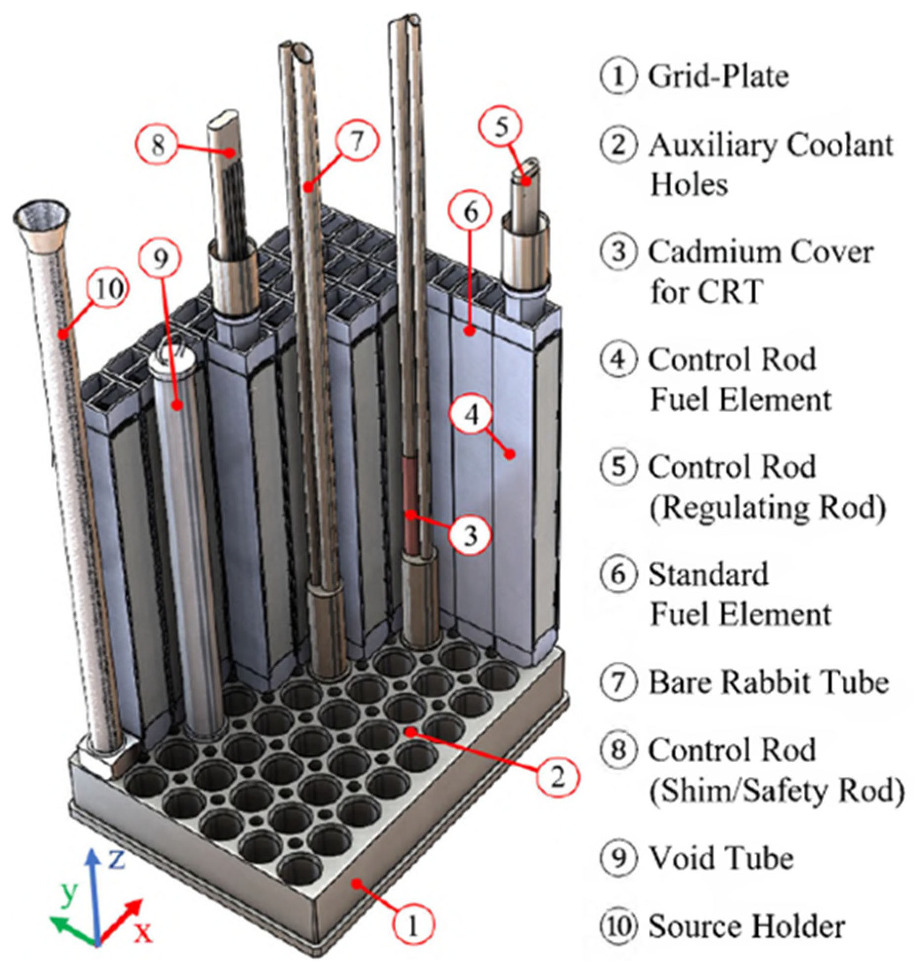
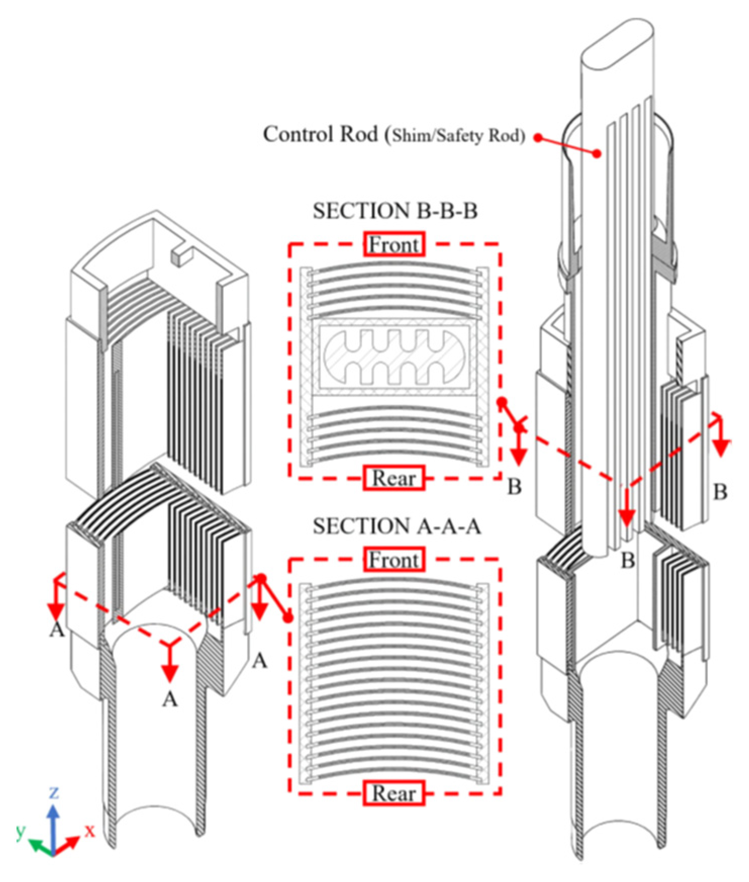
2.1. Core Description

As a pool-type research reactor, the MSTR core is submerged in water about 20 ft. (609.6 cm) deep from the top of the pool surface [13]. All constituent elements of the reactor core are installed in a 12.7 cm thick aluminum grid plate. The grid plate contains 54 equally spaced (6 × 9) holes with approximately 6.14 cm diameters that support and hold the core element assemblies, as shown in Figure 1. Additionally, the MSTR contains 40 coolant holes and, in order to support those holes, between every four holes, there are axillary holes that allow the water to pass through intersection channels between elements. Each coolant hole in MSTR is 2.22 cm in diameter. In addition, the MSTR accommodates one source holder, a bare rabbit tube (BRT), a cadmium-lined rabbit tube (CRT), and a hot cell rabbit tube (HCRT) [13]. All MSTR core elements are visually shown in Figure 1.
As shown in Figure 2, a core configuration of 120 W is represented. The MCNP5 model was performed with this configuration but without the HCRT [11], as represented in the figure. This was also applied to the validity study of SCALE6 that had been performed [13].
The fuel elements (F) consist of 18 curved MTR plate-type fuels as shown in Figure 3. A single “fuel meat” plate has a thickness and a length of 0.05 cm and 59.05 cm, respectively, with a cross-section area of 0.31 cm2. The MSTR fuel consists of the uranium silicide-aluminum (U3Si2-Al) fuel (19.75% 235U) clad in a layer of aluminum alloy 6061 (0.04 cm), with a total thickness of 0.13 cm [12]. The water gap between fuel plates is approximately 0.32 cm [13]. The fuel elements (C) have control rods, guide tubes, and 10 fuel plates. Fuel plates are equally spaced from each other for the geometric homogeneity of the reaction. The location of the fuel plates is in the front and rear of the fuel element (C), which leaves a gap in the center (C) of the control rod (CR) for the guide tube.

2.2. OpenMC Model

For modeling complex geometric objects, OpenMC uses a constructive solid geometry representation. Closed volumes, or cells, can be represented as the intersection of multiple half-spaces. Each half-space is in turn defined as the positive or negative side of a plane or quadratic surface. This allows curved surfaces such as spheres and cylinders to be modeled exactly with zero tolerance due to mesh discretization, which allows for higher accuracy in the simulations. In addition, OpenMC has a flexible, low-overhead tally system that enables users to obtain physical results of interest. Tallies are defined by combinations of filters and scores. Each filter limits what events can be added to the tally based on the attributes of the particle [7].
For validation purposes, the MSTR core was simulated through the OpenMC code by performing k-eigenvalue and axial flux calculations. The OpenMC results were compared to the MCNP and SCALE6 model results. For reasonable comparison, the OpenMC model was run under the same conditions simulated in both codes, namely, using the same nuclear data library of ENDF/B-VII.1 for a 120 W core configuration based on the experimental validation study [12], but without the HCRT. The adopted cross-section libraries for the OpenMC code were defined at a temperature of 293.6 K. In addition, the fuel was assumed to be fresh, and the initial neutron source was assumed to be a uniform source distribution throughout the fissile material for all models. However, modeling of the control rods was neglected, which means the comparison was limited to the results of fully withdrawn control rods. In the same manner, similar to the SCALE6 and MCNP models [12,13], the OpenMC was run with 1015 batches, with 15 inactive batches to be skipped, and 20,000 particles in each batch for the study. Figure 4 shows top views of the MSTR core, as demonstrated before in Figure 2, for both the MCNP5 and OpenMC models.
For the difference study, the following Equations (1) and (2) were used to determine the bias Δ k in percent mille (pcm) for the determined multiplication factor and its uncertainty σ Δ k (pcm) [13]:
Δ k = k e f f k e f f × 10 5
σ Δ k = σ k e f f 2 + σ k e f f 2 × 10 5
where   k e f f and σ k e f f are the determined multiplication factor and its uncertainty, respectively, while   k e f f and σ k e f f are the reference multiplication factor and its uncertainty, respectively. As mentioned before, the ENDF/B-VII.1 library was activated for the OpenMC model. However, the axial flux generated in the literature utilized the ENDF/B-VI (0.66 c) library instead [12]. In terms of geometry configuration, a simplified configuration has been established compared to the MCNP and SCALE6 models [12,13]. In past studies, the MCNP5 version model was used; however, it had been updated by using the MCNP6 version with the ENDF/B-VII.1 library, with the same geometrical model shown in Figure 5 [13]. On the other hand, in the SCALE6 simulation literature, three MSTR configurations were simulated: (a) the MSTR core (the main unit only), (b) the MSTR pool, which contains identical geometry of the MCNP model, and (c) the high-fidelity model, which includes configurations (a) and (b) plus fully detailed thermal columns and beam ports with the entire MSTR building structure. All SCALE6 MSTR geometrical configurations are shown in Figure 6.
For the OpenMC model, the geometrical configuration was similar to model (a), as in the SCALE6 model. Further, the OpenMC model was taken as only submerged in the cubical reactor pool, without modeling the control rods, thermal column, neutron beam port, or the surrounding concrete structure, as shown in Figure 7. All MSTR material compositions were taken from the previous literature [12,13]. Table 1 lists all the material compositions as simulated in the OpenMC model.

2.3. Axial Flux Profile

In order to validate the flux profile inside the core, a cell copper wire was simulated in the OpenMC model as shown in Figure 8. The code was simulated to calculate the volume flux tally filtered by the cell-id to determine the absorption rate. The modeled wire was 127 cm long and had a diameter of 0.06 cm. The wire was inside the same fuel element, located at grid spacing D6. The volume flux tally was coded for this cell with 50 meshes. Furthermore, the material used for this cell was assumed to be pure copper with a ratio of naturally occurring isotopes. The MSTR OpenMC axial flux profile was compared to the experimental results and MCNP5 simulation code fluxes [12].

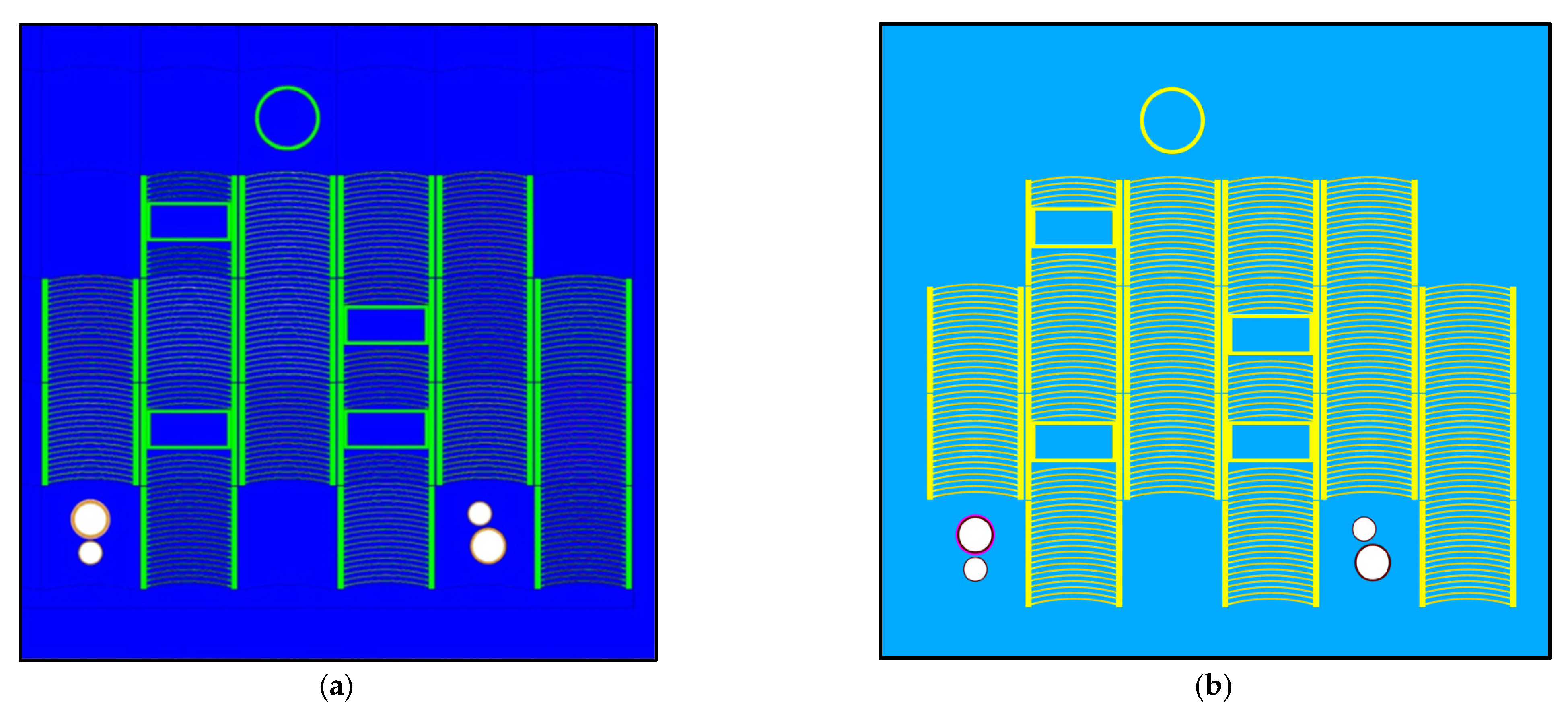
2.4. Flat Fuel Plates

After validating the OpenMC code through k e f f values and axial flux profiles, the MSTR fuel plates were simulated as flat fuel plates (non-curved). All conditions and parameters were kept the same. However, changing the fuel plate shape into a flat plate requires modifying the fuel dimensions in order to keep the fuel volume fixed. In addition, the fuel height will remain unaffected, but the dimensions of the flat fuel plate will be determined by the cross-sectional area. The cross-sectional area was then used to determine the width of the flat plate while keeping the thickness unchanged. Equation (3) is used to identify needed modifications as follows:
A r e a c u r v e d = A r e a f l a t
where A r e a c u r v e d is the area of the curved plates while A r e a f l a t is the area of the flat plates.
θ × r o u t 2 r i n 2 = r e g t a n g u l a r   l e n g t h × t h i c k n e s s
where θ stands for the angle of curvature (degree) that is used to calculate the area of the arc. The parameters r o u t and r i n are the outer and inner radii of the curve, respectively.
t h i c k n e s s = r o u t r i n
Thus, the flat fuel plate thickness needs to be redefined in order to keep the volume fixed in both simulations. Figure 9 shows the top view of simulated curved and flat fuel plates.

3. Results and Discussion

3.1. Validation of Core Model
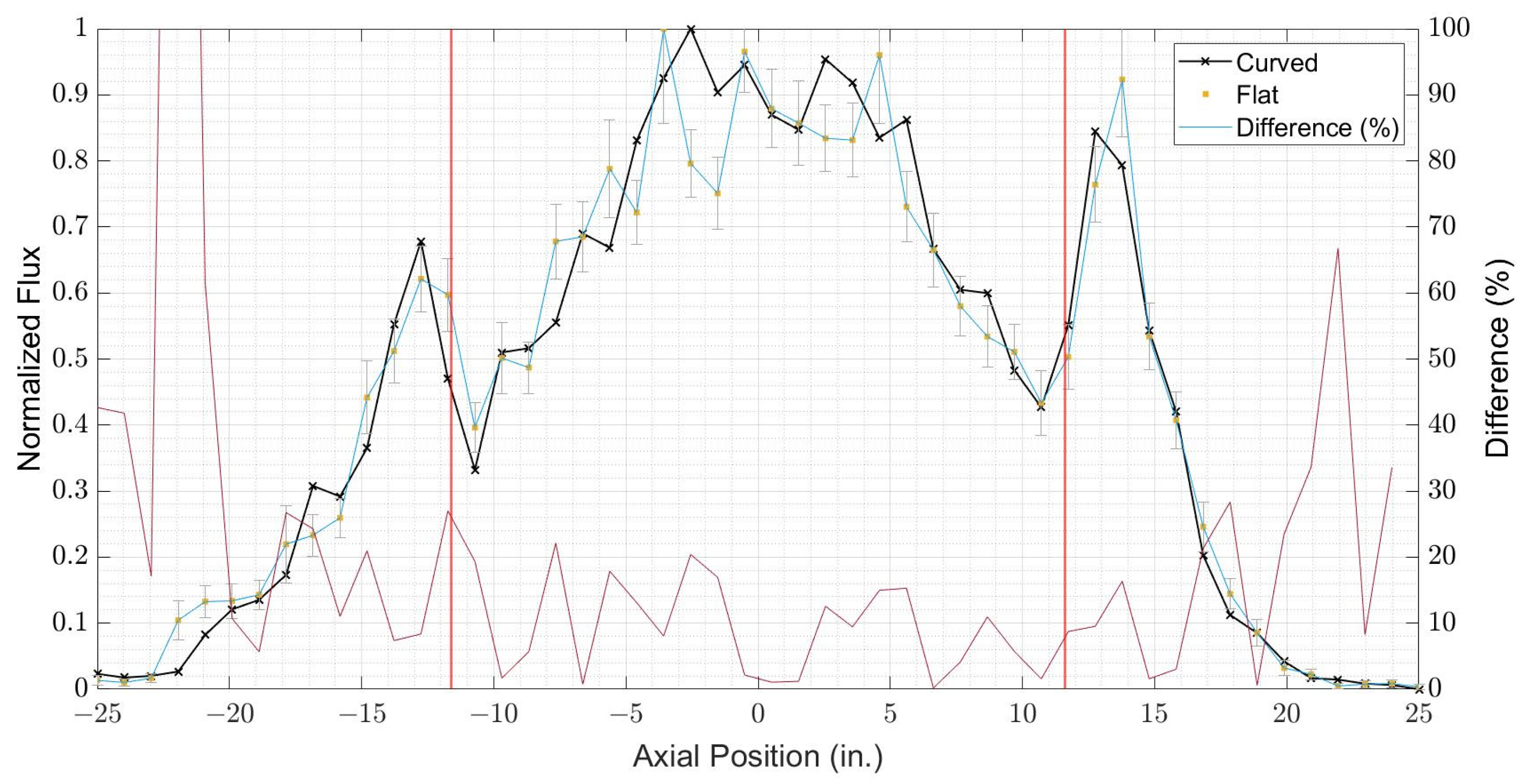
Reactor criticality is perhaps the most important parameter to evaluate a nuclear reactor, and it is described by a multiplication factor k eigenvalue ( k for an infinite reactor and k e f f for a finite reactor). The multiplication factor indicates the MSTR reactor criticality factor. The k e f f calculated by using the OpenMC model and the values generated from previous studies [12,13] are listed in Table 2.
The k e f f values were obtained from previous studies [12,13] and indicate the criticality of the reactor when all control rods are fully withdrawn (full natural fission reaction inside the core with no active control of reactivity), which has been adopted by the OpenMC model. As shown in Table 2, the difference between OpenMC, MCNP, and (b)SCALE6 is between 202 × 10−5 and 80 × 10−5 pcm. However, the value difference with (a)SCALE6 is neglected, since model (a) has not included the pool geometry (only the core structure). Moreover, k e f f value differences between the OpneMC model and other models are mainly due to inconsideration of surrounding structures such as the thermal column, the thermal neutron beam port, and the surrounding concrete structure.

3.2. Axial Flux

The flux profiles of the MSTR experimental work, the MCNP5 model [12], the OpenMC model, and the error percentage between the MCNP5 and OpenMC curves are plotted in Figure 10. Generally, the obtained neutron flux profile for curved fuel simulation matched well with previously measured experimental work and the flux profile obtained by using the MCNP5 code [12]. For comparison purposes, each mesh-tally value was normalized to its maximum value. Moreover, the discrepancy between the MCNP5 flux profile and OpenMC was below 20% in the active region while it reached more than 40% in the edges of the core. Several inconsistent conditions could be the reason for the slight differences between the OpenMC model, the experimental data, and MCNP5 model flux profiles. For instance, the experimental copper wire position at the D6 assembly was not defined in the experimental setup, as well as for the MCNP5 simulation [12]. In addition, using different neutron data libraries might slightly increase the variation between the OpenMC and MCNP5 flux profiles. Nevertheless, the maximum point and wings peaks were matched with the same points as the MCNP5 simulation flux profile.

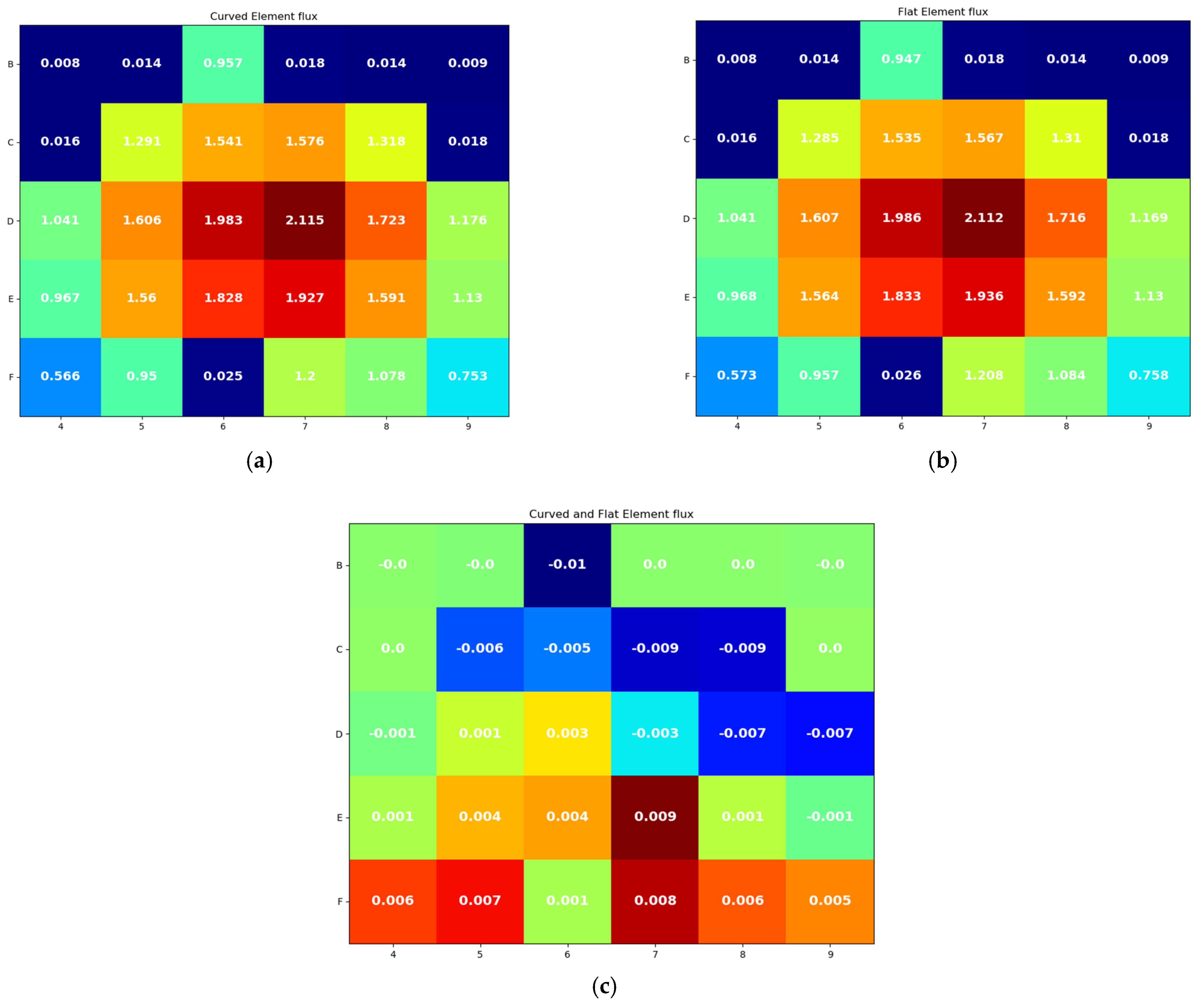
3.3. Difference between Flat and Curved Core

After the curved core was verified with previous studies, the flat fuel core was simulated and compared with OpenMC curved fuel results. k e f f of the curved and flat simulations are listed in Table 3. From Table 3, k e f f has a higher value in flat shape fuel meat core than curved shape by 102 ± 32 × 10−5 pcm. In addition, the axial flux of flat fuel shape was obtained and plotted with curved core flux for comparison purposes as shown in Figure 11. Obviously, the flux peak locations have been slightly changed. Moreover, most of the total flux points were adjusted, especially in the active fuel region between the red vertical lines (wings) and lower region of the core. The discrepancy between the flux profiles was determined between 2% and 27% in the active region of the core. However, the shape of the flux profile did not change at the region above the core.
In Figure 12 and Figure 13, the radial flux and fission distribution for both models were implemented, respectively. The difference was found after normalization, which is obtained by dividing by the mean values. It is essential that flux and fission do not exceed 0.009 nor go below −0.01. The radial flux and fission distribution differences, as shown in Figure 12c and Figure 13c, were found to be mainly in the fuel section. However, the location of the hot fuel element has remained unchanged. There was also an exception to the difference in flux occurring in the location of the pipe holding the source (B6).

4. Conclusions

For the simulation of the curved fuel shape, the OpenMC model was used to simulate all the core components except the control rods, thermal column, neutron beam port, and the surrounding concrete structure. As a result, the majority of the variation in OpenMC code with the MCNP and SCALE models can be explained by ignoring the surrounding structures. However, it is seen that the OpenMC multiplication factor as well as the axial flux values have some discrepancy with the other codes. Furthermore, the difference in multiplication factor between the OpenMC, MCNP, and SCALE6 models did not exceed 202 × 10−5 pcm. On the other hand, the discrepancy between the OpenMC and MCNP5 flux profiles in the active core region is below 20%. In order to minimize the differences, adding the surrounding structure along with a higher number of simulated particles can be proposed for further studies. Nevertheless, OpenMC outcomes have shown adequate results, which have validated the model of the curved fuel shape. On the other hand, comparing experimental MSTR axial flux with the simulated OpenMC code shows a higher discrepancy, since the OpenMC model uses fresh fuel and does not consider several years of fuel operation. Thus, this can also be an area of future investigation, since a long time of fuel operation will change the behavior of the fuel interaction and thus the kinetics of the reaction.
The OpenMC models have considered only the fuel plate shape, which means that the volume and amount of the fuel material are the same for the curved and flat fuel elements. By comparing the fuel shape results, a slight difference has been observed in terms of the multiplication factor (≈ 10−3 pcm) due to the reactor being utilized in a super-critical mode because of the withdrawn state of the control rods in the simulation. In addition, the overall axial flux profile shape shows only a little discrepancy; for instance, the maximum error percentage is 27% within the active core region. Moreover, the radial flux distribution and the radial fission (power) distribution have no significant difference due to the fuel mass similarity. In conclusion, the use of a flat fuel plate shape is easier to code for most simulation tools than the curved shape. In addition, the flat-shaped fuel results are reasonable enough for MTR reactors. However, in the case of more in-depth studies, the flat fuel shape simulations of MTR reactors might carry some discrepancies. Nevertheless, this work has effectively demonstrated the effect of curved fuel plates in an MTR reactor to contribute to the literature and can be taken as a base study for building up on the results.

Author Contributions

Conceptualization, A.H.A. and A.A.A.; methodology, A.H.A. and A.A.A.; simulation code, A.H.A.; data curation, A.H.A. and A.A.A.; writing—review and editing, A.H.A. and A.A.A.; supervision, A.I.A. All authors have read and agreed to the published version of the manuscript.

Funding

This research was funded under the joint agreement between King Abdullah City for Atomic and Renewable Energy (K.A.CARE) and King Saud University with grant number K.A.CARE-KSU2022-3001.

Institutional Review Board Statement

Not applicable.

Informed Consent Statement

Not applicable.

Data Availability Statement

Not applicable.

Acknowledgments

The authors would like to thank Abdulaleem Bugis for his support.

Conflicts of Interest

The authors declare no conflict of interest.

References

  1. International Atomic Energy Agency (IAEA). Applications of Research Reactors; IAEA Nuclear Energy Series No. NP-T-5.3; IAEA: Austria, Vienna, 2014. [Google Scholar]
  2. International Atomic Energy Agency (IAEA). Research Reactors: Purpose and Future; IAEA: Austria, Vienna, 2016. [Google Scholar]
  3. Phillips Petroleum Company. Fundamentals in the Operation of Nuclear Test Reactors: Volume 2; University of North Texas Libraries, UNT Digital Library: San Francisco, CA, USA, 1963; Available online: https://digital.library.unt.edu/ark:/67531/metadc100236/ (accessed on 2 June 2022).
  4. Huffman, J.R. The Materials Testing Reactor Design; U.S. Atomic Energy Commission: Washington, DC, USA, 1953. Available online: https://www.osti.gov/servlets/purl/4406959 (accessed on 19 June 2022).
  5. World Nuclear Association. Available online: https://world-nuclear.org/information-library/non-power-nuclear-applications/radioisotopes-research/research-reactors.aspx (accessed on 8 November 2022).
  6. Duderstadt, J.J.; Hamilton, L.J. Nuclear Reactor Analysis, 1st ed; John Wiley & Sons Ltd.: New York, NY, USA, 1976. [Google Scholar]
  7. Seamone, A. Thermal-Hydraulics Feasibility for an Ultra-Compact Nuclear Reactor Core Assembly. In Proceedings of the 2019 SURF Symposium, Reactor Operations and Engineering, New York, NY, USA, 6 August 2019; Available online: https://www.nist.gov/document/thermal-hydraulics-feasibility-anultra-compact-nuclear-reactor-core (accessed on 12 July 2022).
  8. Romano, P.K.; Horelik, N.E.; Herman, B.R.; Nelson, A.G.; Forget, B.; Smith, K. OpenMC: A State-of-the-Art Monte Carlo Code for Research and Development. Ann. Nucl. Energy 2015, 82, 90–97. [Google Scholar] [CrossRef] [Green Version]
  9. MacConnachie, E.L.; Novog, D.R. Measurement, simulation, and uncertainty quantification of the neutron flux at the McMaster Nuclear Reactor. Ann. Nucl. Energy 2021, 151, 107879. [Google Scholar] [CrossRef]
  10. Alqahtani, M.; Day, S.E.; Buijs, A. OSCAR-4 Code System Comparison and Analysis with a First Order Semi-Empirical Method for Core-Follow Depletion Calculation in McMaster Nuclear Reactor (MNR). CNL Nuclear Rev. 2019, 9, 73–82. [Google Scholar] [CrossRef]
  11. Alhuzaymi, T.M. Reactor Configurations to Support Advanced Material Research. Ph.D. Thesis, Missouri University of Science and Technology, Rolla, MO, USA, 2019. [Google Scholar]
  12. Richardson, B.; Castano, C.H.; King, J.; Alajo, A.; Usman, S. Modeling and validation of approach to criticality and axial flux profile experiments at the Missouri S&T Reactor (MSTR). Nucl. Eng. Des. 2012, 245, 55–61. [Google Scholar]
  13. Bugis, A.A. Modeling a Nuclear Research Reactor and Radiation Dose Estimation in an Accident Scenario. Ph.D. Thesis, Missouri University of Science and Technology, Rolla, MO, USA, 2020. [Google Scholar]
Figure 1. The MSTR core elements. Figure is taken from [13].
Processes 11 00637 g001
Figure 2. MSTR core configuration (120 W) [12,13].
Processes 11 00637 g002
Figure 3. Sketch of (F) left and (C) with an inserted CR (shim/safety rod) right. Figure is taken from [13].
Processes 11 00637 g003
Figure 4. XY top-view horizontal cross-section of the MSTR core as modeled in (a) MCNP5 and (b) OpenMC. a is taken from [12].
Processes 11 00637 g004
Figure 5. MSTR MCNP6 model (left) ZY side view (right) XY top view. Figure is taken from [13].
Processes 11 00637 g005
Figure 6. Three geometrical configuration models used in SCALE6 (a) the MSTR core, (b) the MSTR pool, and (c) the high-fidelity model, which includes the pool and entire MSTR building structure. Figure is taken from [13].
Processes 11 00637 g006
Figure 7. Full cross-sectional view of the OpenMC model: (a) XY-axis plan view with color code; (b) YZ-axis plan view, where the black borders represent the model geometric boundary.
Processes 11 00637 g007
Figure 8. The modeled copper wire: (left) XY-axis top view; (right) YZ-axis side view.
Processes 11 00637 g008
Figure 9. Top view of (a) curved fuel plates and (b) flat fuel plates.
Processes 11 00637 g009
Figure 10. MSTR flux profile produced by the MCNP5 and OpenMC models. MCNP5 flux data were obtained from reference [12], where the difference (%) line indicates the error percentage between MCNP5 and OpenMC, while the vertical red line indicates the active fuel region.
Processes 11 00637 g010
Figure 11. The axial flux for curved and flat core; difference (%) line indicates the error percentage between curved and flat values, while the vertical red line indicates the active fuel region.
Processes 11 00637 g011
Figure 12. Radial flux of (a) curved fuel, (b) flat fuel, and (c) the difference between the fluxes.
Processes 11 00637 g012
Figure 13. Radial fission distribution of (a) curved fuel, (b) flat fuel, and (c) the difference.
Processes 11 00637 g013
Table 1. Material composition used in the OpenMC model.
MaterialIsotopic Composition (Atomic Percentage [a/o])
U3Si2-Al
(19.75% enriched)
U-238(0.129533)Si-28(0.099366)Si-30(0.003326)
U-235(0.032287)Si-29(0.005046)Al-27(0.730443)
Wrought 6061 Al-alloy
(Cladding)
Al-27(0.978233)Fe-54(0.000133)Cr-52(0.000939)
Si-28(0.006140)Fe-56(0.002093)Cr-53(0.000106)
Si-29(0.000312)Fe-57(0.000048)Cr-54(0.000026)
Si-30(0.000206)Fe-58(0.000006)Cu-63(0.000811)
C-nat(0.010536)Cr-50(0.000049)Cu-65(0.000362)
Cast A356-T6 Al-alloy
(Fuel element handle)
Al-27(0.928066)Ti-nat(0.000736)Zn-nat(0.000124)
Si-28(0.061640)Fe-54(0.000031)Mn-55(0.000099)
Si-29(0.003130)Fe-56(0.000490)Cu-63(0.000029)
Si-30(0.002063)Fe-57(0.000011)Cu-65(0.000013)
C-nat(0.003567)Fe-58(0.000002)
1100-series Al
(Grid plate)
Al-27(0.999469)Cu-63(0.000367)Cu-65(0.000164)
Stainless steel 304
(Handle of C elements)
Fe-54(0.040229)Cr-52(0.169327)Ni-61(0.001020)
Fe-56(0.631511)Cr-53(0.019200)Ni-62(0.003253)
Fe-57(0.014584)Cr-54(0.004779)Ni-64(0.000829)
Fe-58(0.001941)Ni-58(0.060938)Mn-55(0.020133)
Cr-50(0.008781)Ni-60(0.023473)
CadmiumCd-106(0.012500)Cd-111(0.128000)Cd-114(0.287300)
Cd-108(0.008900)Cd-112(0.241300)Cd-116(0.074900)
Cd-110(0.124900)Cd-113(0.122200)
CopperCu(nat *)
* Naturally occurring isotopes provided by OpenMC.
Table 2. Composition of k e f f results. OpenMC, MCNP6, and SCALE6. MCNP6 and SCALE6 k e f f data were obtained from references [12] and [13], respectively.
Models k e f f +/− σ Δ k e f f +/− Δ σ
× 10 5 × 10 5   Δ k e f f p c m
OpenMC1.00967+/−23 r e f
MCNP61.00765+/−17202+/−29
(a)SCALE6-CE *0.98992+/−211975+/−31
(a)SCALE6-MG **0.99009+/−191958+/−30
(b)SCALE6-CE *1.00888+/−2179+/−31
(b)SCALE6-MG **1.00947+/−1920+/−30
(c)SCALE6-CE *1.00849+/−19118+/−30
(c)SCALE6-MG **1.00886+/−2081+/−30
* Continuous energy (CE) cross-section. ** Multi-group (MG) cross-section. (a), (b) and (c) are the SCALE6 models as described in reference [13].
Table 3. k e f f results of the curved and flat core.
Models k e f f +/− σ Δ k e f f +/− Δ σ
× 10 5   × 10 5   Δ k e f f p c m
Curved 1.00967+/−23 r e f
Flat1.01069+/−22102+/−32
Disclaimer/Publisher’s Note: The statements, opinions and data contained in all publications are solely those of the individual author(s) and contributor(s) and not of MDPI and/or the editor(s). MDPI and/or the editor(s) disclaim responsibility for any injury to people or property resulting from any ideas, methods, instructions or products referred to in the content.

