Article

A Study on Activity of Coexistent CO Gas during the CO2 Methanation Reaction in Ni-Based Catalyst

Department of Environmental Energy Engineering, College of Creative Engineering, Kyonggi University, 94 San, Iui-dong, Youngtong-gu, Suwon-si 16227, Republic of Korea
*
Author to whom correspondence should be addressed.
Processes 2023, 11(2), 628; https://doi.org/10.3390/pr11020628
Submission received: 17 January 2023 / Revised: 15 February 2023 / Accepted: 16 February 2023 / Published: 18 February 2023

Abstract

:
Greenhouse gases, the main cause of global warming, are generated largely in the energy sector. As the need for technology that has reduced greenhouse gas emissions while producing energy is on an increase, CCU technology, which uses CO2 to produce CH4 (SNG energy, synthetic natural gas), is drawing attention. Thus, the reaction for converting CO2 to CH4 at a specific temperature using a catalyst is CO2 methanation. The field of CO2 methanation has been actively studied, and many studies have been conducted to enhance the activity of the catalysts. However, there is a lack of research on the variables that may appear when CO2 methanation is attempted using emissions containing CO2 generated from industrial fields and bio-plants. According to previous studies, it is reported that realistic feed gases from gasification or biomass plants contain a significant amount of CO. this study is a follow-up study focused on the application of CO2 methanation in various real processes. In the CO2 methanation reaction, a study was conducted on the catalyst efficiency and durability of CO gas that can coexist in the inlet gas rather than CO2 and H2 gas. The CO2 methanation activity was observed at 200–350 °C when 0–15% CO coexisted using the Ni-Ce-Zr catalyst, and the operating variables were set for optimal SNG production. As a result of adjusting the ratio of inlet gas to increase the yield of CH4 in the produced gas, the final CO2 conversion of 83% and CO conversion of 97% (with 15% CO gas at 280 °C) were obtained. In addition, catalytic efficiency and catalyst surface analysis were performed by exposing CO gas during the CO2 methanation reaction for 24 h. It showed high activity and excellent stability. The results of this study can be used as the basic data when applying an actual process.

1. Introduction

Owing to abnormal climate phenomena and global warming problems that occur worldwide, countries around the world continue to make efforts to solve them [1]. According to a report published by the IPCC, greenhouse gases generated through an-thropogenic activities are the main factors accelerating global warming and among them, it has been studied that many greenhouse gases are emitted from the energy sector. At COP26 (Conference of the Parties 26), where leaders from all over the world gather every year to discuss the topic of climate change, a trend was observed of deepening regulations on fossil fuels that emit large amounts of greenhouse gases, such as reducing coal-fired power generation [2,3,4].
Because of this trend, many countries around the world have adopted several methods, such as not generating CO2, a greenhouse gas, in the final energy production process, or generating a small amount of CO2 wherever possible, or producing energy utilizing CO2. Among them, the technology utilizing CO2 is called Carbon Capture & Utilization (CCU). As a technology that captures and utilizes CO2, CCU can produce energy in an eco-friendly way while solving environmental problems because it can be converted into an energy source or fuel [5,6,7].
The CO2 methanation reaction, which is one of the methods for chemically converting CO2, a greenhouse gas, into CH4, the main component of natural gas, is a reaction in which 4 mol of H2 and 1 mol of CO2 react to produce 1 mol of CH4 and 2 mol of H2O. The gas produced through the CO2 methanation reaction is attracting attention as a transitional energy source that can replace coal and oil and in doing so only CH4 and H2O are generated and no other harmful substances being generated [8,9].
In the Sabatier reaction, it is known that CO2 methanation occurs as follows (Equation (1)):
CO2 + 4H2 ↔ CH4 + 2H2O, △H°298K = −165 kJ·mol−1
In addition, this reaction (Equation (1)) is hypothesized to be a two-step reaction (Equations (2) and (3)) [10,11].
CO2 + H2 ↔ CO + H2O, △H°298K = 41 kJ·mol−1
CO + 3H2 ↔ CH4 + H2O, △H°298K = −206 kJ·mol−1
In the first step, carbon dioxide and hydrogen are converted into carbon monoxide and water, respectively, through the RWGS reaction as per the separation mechanism. In the next step, carbon monoxide reacts with hydrogen to produce methane and water. If carbon monoxide is not generated as a product, the reactions of Equations (2) and (3) would occur continuously [12,13].
Therefore, it is possible to produce SNG (synthetic natural gas) through the CO2 methanation reaction by utilizing the large amount of CO2 generated in various indus-tries and divert it towards the existing natural gas supply infrastructure. A process ap-plying this concept is the power-to-gas(P2G) project [14,15]. P2G is a technology that produces H2 by water electrolysis using surplus power or converts the produced H2 into CH4 by reacting with CO2 thereby using it as a fuel for heating, power generation, transportation, etc. (Figure 1). While the existing method of energy storage is to store the produced power in secondary batteries, P2G may be distinguished from the existing large-capacity energy storage systems as a way of storing the produced power in the form of gas fuel [5].
Owing to the advantages of these technologies, studies on CO2 methanation have become more diverse. Based on the academic information search provided by the Google portal, as a result of investigating papers published in related research fields from 1990 to 2022 (Figure 2, left), In particular, active research has been conducted since 2010. Figure 2, right shows the fields of CO2 methodology studied over the past 10 years (2012–2022). It also shows that many scientists have studied various aspects of the technology, such as catalyst manufacturing, low-temperature operation, durability improvement, reactor type, mechanism, and computational chemistry, to increase the efficiency of the reaction [16,17,18].
Most studies have been conducted to enhance the activity of catalysts, and studies on catalyst types, process systems, and effects on operating factors for application in actual processes are relatively insufficient. In addition, while studies have been con-ducted in various fields, there are few cases in which this technology has been applied on a large scale in various industries [19,20,21]. This is because of the high efficiency and durability of catalysts, as it is difficult to control competitive catalyst materials, heat load during catalytic reactions, and removal of catalyst inactivation factors, etc. In addition, as by-product gases and biogas emitted from various industries include N2, CO, H2S, H2O, H2, CH4, etc., except for a large amount of CO2, a pre-treatment process is essential to remove other gases that are unnecessary for the CO2 methanation reaction or that have a poisoning effect [22,23,24].
SNG production through CO2 methanation reaction is (1) most suitable for application where a large amount of CO2 is generated, and energy independence is required, and (2) this technology can be applied to places where carbon gases such as CO2 and CO are generated. It can be applied to the COx methanation process by utilizing CO2, CO, and H2 of biogas produced from by-product gases or organic waste resources generated in various industrial fields. The properties of outlet gas emitted from various industries and bio plants are shown in a Table 1 [25,26].
According to the properties of gases presented in Table 1, it can be seen that there are gases that are unnecessary for CO2 methanation or cause catalyst inactivation. Therefore, before injecting gas into the CO2 methanation process, a pre-treatment process is essential to maintain the type and concentration of the inlet gas constant.
However, in actual plants, gas that has not been pre-treated unexpectedly flows into the main process of CO2 methanation temporarily. This situation can occur in a process in which continuous/multiple technologies are concentrated, consisting of a pre-treatment process, a main process, a post-treatment process, and catalysts applied to actual processes must have stable efficiency and durability even in these variables.
Prior studies and surveys have shown that realistic feed gases from gasification or biomass plants contain significant amounts of CO. Therefore, the CO2 methanation process applied to the actual industry needs a flexible response depending on the situation.
This follow-up study focused on the applicability of CO2 methanation in various practical processes. A previous study reported that if a small amount of CO gas was supplied together in the reaction, surface reconstruction appeared or the active metal was deactivated. This can lead to the deactivation of Ni-based catalysts by carbon deposition and Ni(CO)x species on Ni surfaces during CO2 methanation [27,28,29]. Therefore, the catalytic reaction and durability were observed when CO gas coexisted during the CO2 methanation reaction.
In order to use the outlet gas produced through the methanation reaction as a fuel, it must be finally made into SNG through an upgrading process. Since the upgrading process differs according to the SNG quality standards required by the user, not only COx conversion but also the concentration of outlet gas are important information. Therefore, this study observes the activity result when 0–15% CO is coexisted into CO2 methanation and test an operating plan to increase CH4 production. In addition, the presence of deactivation factors such as carbon deposition or sintering was observed through a lifetime test.

2. Materials and Methods

2.1. Preparation of Catalysts

The Ni-Ce-Zr catalysts were used in this study, which have shown excellent CO2 methanation performance in previous studies [16]. The reagents used in the preparation of the Ni-Ce-Zr catalyst were Ni powder (99.7%, Sigma-Aldrich Chemical Co., St. Louis, MO, USA), cerium nitrate hexahydrate (99.9%, Sigma-Aldrich Chemical Co., St. Louis, MO, USA), and zirconium oxide (99%, Sigma-Aldrich Chemical Co., St. Louis, MO, USA), which were prepared using the wet impregnation method. The catalysts were mixed with Ni:Ce:Zr at a weight ratio of 1:0.2:0.1, and after stirring the slurry-state mixed solution for more than 1 h, the moisture was evaporated using a rotary vacuum evaporator (DAIHAN Scientific Co., Seoul, Republic of Korea). After drying in a dry oven for 24 h at 105 °C to remove the moisture contained in the micropores, it was sintered at a high temperature with air gas injected. Obtained samples were sieved using a 40–50 mesh to produce the powder-type catalysts.

2.2. Experimental Equipment and Activity Test

CO2 methanation experiments were conducted in a fixed-bed reactor at atmospheric pressure. The fixed-bed reactor is composed of a gas injection part, a main reactor, a moisture remover, and a reaction gas analyzer and consisted of stainless steel. The gases supplied to the gas inlet were H2, CO2, CO, and N2, and the flow rate was constantly controlled using a mass flow controller (MFC, MKS Co., Andovor, MA, USA). The volume ratio of H2:CO2 was fixed at 4:1, and when CO gas was injected, the amount of N2 injection gas was reduced and CO was injected by adjusting the amount according to the concentration (Figure 3). In order to observe the conversion according to the reaction temperature, the conversion was observed for 1 h at each reaction temperature. The total gas flow rate was 120 mL/min at 25 °C and 1 atm. For all tests, the catalyst load was fixed at a value of 500 mg (the samples has a density of about 1 g/cm3). The catalytic reaction was measured in the reactor temperature range of 350 °C to 200 °C, after the reaction, moisture was removed from the moisture-removing device before the gas was flown into the analyzer. This was followed by gas chromatography (YL 6500GC) which used to analyze the properties of the reaction gas. The space velocity of the catalysts was calculated using Equation (4) and tested at 14,440 h−1. The reaction activity of the catalysts was expressed as COx for the conversion of CO2 and CO as the reaction gases, and calculated using Equations (5) and (6).
GHSV   ( Gas   Hour   Space   Velocity )   ( h 1 ) = Q i n V c a t .
CO x   conversion   ( % ) = F ( C O x i n ) F C O x o u t F C O x i n × 100
CH 4   selectivity = F C H 4 ,   o u t F C O 2 , i n + C O i n F C O 2 , o u t + C O o u t
A stability test was conducted at 300 °C for 24 h under the same experimental squence and conditions.

2.3. Catalyst Characterization

EDS (JEOL Co., Tokyo, Japan) was used to observe the surface of the catalysts after pro-longed CO2 methanation with the Ni-Ce-Zr catalysts (Table 2). Through EDS point and mapping analyses, the characteristic X-rays for each element emitted from the surface of the samples were detected in the form of energy, and qualitative as well as quantitative analyses were conducted on the elements contained in the corresponding areas. X-ray diffraction analysis (XRD) is the most commonly used to confirm structure and crystalline. The test was performed on the High Power X-ray Diffractometer (Rigaku Co., Tokyo, Japan) with a Cu radiation source (40 KV, 150 mA). The XRD patterns were recorded between 10°–90° (2ϴ).

3. Results and Discussion

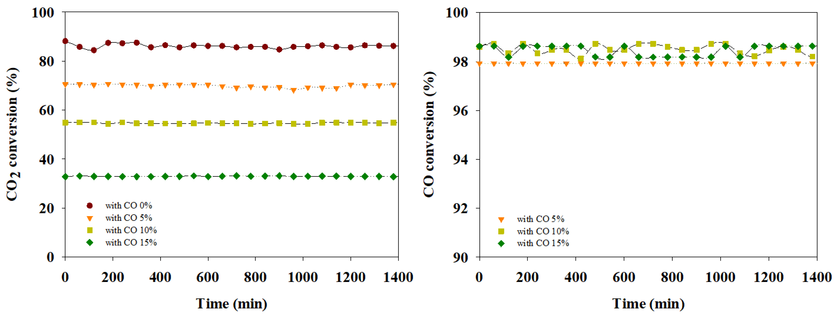
3.1. Results for CO2 Methanation Catalytic Activity When CO Gas Exists

In this study, CO was injected after adjusting the concentration to 0–15% of the inlet gas (CO2 + H2) during the CO2 methanation reaction, and the conversion of CO2 and CO was observed at a reaction temperature of 200–350 °C. The results of the experiment are shown in Figure 4, CO2 conversions of 350 °C were 83%, at 300~220 °C were 84~87%, and at 200 °C were 79% for CO uninjected (Figure 4a) by CO2 methanation, which is a catalytic reaction between CO2 and H2, and at this time, CH4 selectivity is 1. This was confirmed to be a high performance accoding to the thermodynamic equilibrium (Figure S1) [30,31]. In Figure 4b–d, which was introduced with CO 5–15% based on inlet gas (CO2 + H2), CO2 methanation and CO methanation could be observed simultaneously. CO2 conversion was lower as the CO concentration increased, and CO conversion was high for all experimental conditions.
For CO conversion, it showed a high methanation reaction of 98–99% under all conditions of Figure 4b–d at 350–200 °C, but for CO2 conversion, it was lower as the CO concentration increased in order as seen from Figure 4b to Figure 4d.
As shown by 72 ± 3% in the case of Figure 4b, 53 ± 2% in the case of Figure 4c, and 32 ± 2% in the case of Figure 4d, higher the concentration of CO in the inlet gas, lower the CO2 conversion. When hydrogenation experiments of CO and CO2, there is a research result that the conversion of CO2 set in after almost complete conversion of CO, which was the same as the result of this study. According to prior studies, it has been reported that the presence of CO in the feed gas results in competitive adsorption of CO and CO2 at metal active sites, resulting in reduced CO2 conversion [32,33]. However, when CO coexists in the inlet gas, CO gas can be a positive C source in the methanation reaction if only the catalyst deactivation factor caused by CO is controlled. Therefore, CO and CO2 methanation and outlet gas composition were observed by adjusting the composition of H2, the limiting reactant, in the inlet gas [34].

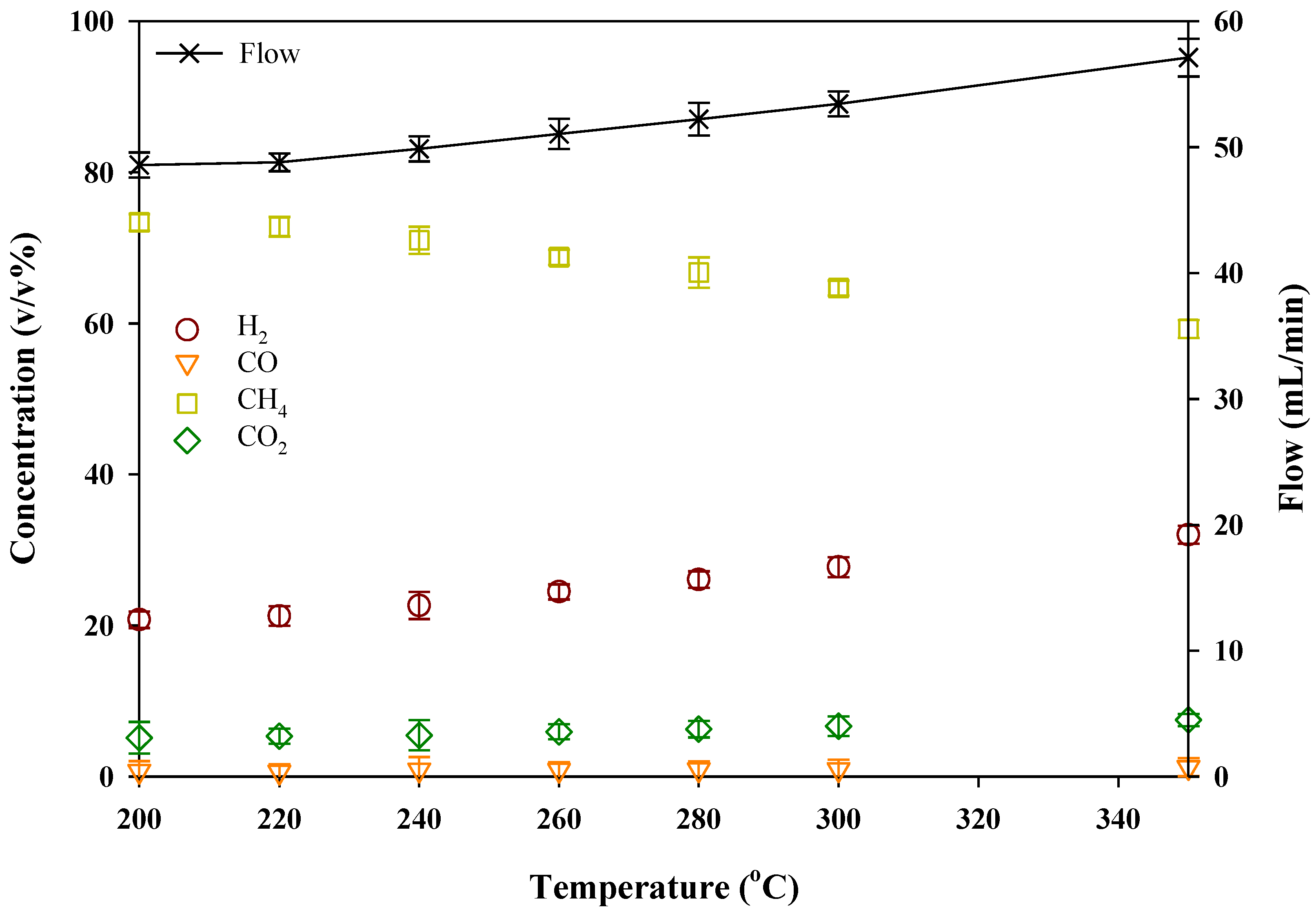
3.2. The Composition of the Final Outgas through CO & CO2 Methanation

The composition of outlet gases produced after the methanation reaction was observed based on the results of the experiment described in Section 3.1. The gases produced through CO2 and CO methanation include CH4 and H2O as well as unreacted H2, CO2, and CO. Excluding the unreacted N2 gas injected into the inlet gas for analysis, are shown in Figure 5 and Figure 6. In addition, H2O included in the outlet gas was removed by cooling and was not included in the outlet gas composition.
According to the result, High-purity CH4 gas can be obtained because higher the conversion of CO2 and CO, lower is the concentration of unreacted gases. As per the results shown in Figure 5 and Figure 6, because the CO conversion is high, the un-reacted CO in the gases produced remains in a small amount, while CO2 that is not converted due to the lack of H2 as the limiting reactant remains in a large amount. The concentrations in the outlet gas at 260 °C of a-d conditions were as follows: (a) 33.5%(H2), 8.5%(CO2), 58%(CH4)/(b) 12.3%(H2), 0.3%(CO), 18.5%(CO2), 68.9%(CH4)/(c) 0.43%(H2), 0.41%(CO), 28.16%(CO2), 71%(CH4)/(d) 0.1%(H2), 0.64%(CO), 35.19%(CO2), 64.07%(CH4). Since SNG requires methane content of 90–95% or more [35], the quality of CH4 of about 70% must be raised to 90% or more through post-processing.

3.3. The Methanation Reaction for an Optimum Production of SNG

In order to produce SNG gas requiring high CH4 purity, COx methanation was performed by adjusting the ratio of inlet gas. H2, the limiting reactant, in the volume ratio of H2:CO2 = 4:1 and H2:CO = 3:1, that the reactants CO and CO2 could sufficiently react, and observed the methanation reaction at 350–200 °C.
First, with respect to the CO2 conversion, a higher conversion of 79% to 88% was observed as the temperature decreased from 350 °C to 200 °C, as shown in Figure 7, indicating a high conversion rate similar to the trend of (a) in Figure 4 where CO was not injected. On the other hand, CO conversion showed a high conver-sion rate of 97% or more over the entire temperature range. Therefore, the gas produced by high conversion of CO2 and CO contained a high content of methane and a small amount of unreacted gases (CO2, CO, and H2) as seen in Figure 8. As shown in Figure 8, the appearance of the concentration of outlet gas was H2 20.8%, CO 0.73%, CO2 5.13%, CH4 73.4% (200 °C, N2, H2O removed). A tendency for CH4 production to increase due to high COx conversion at low temperatures was observed.

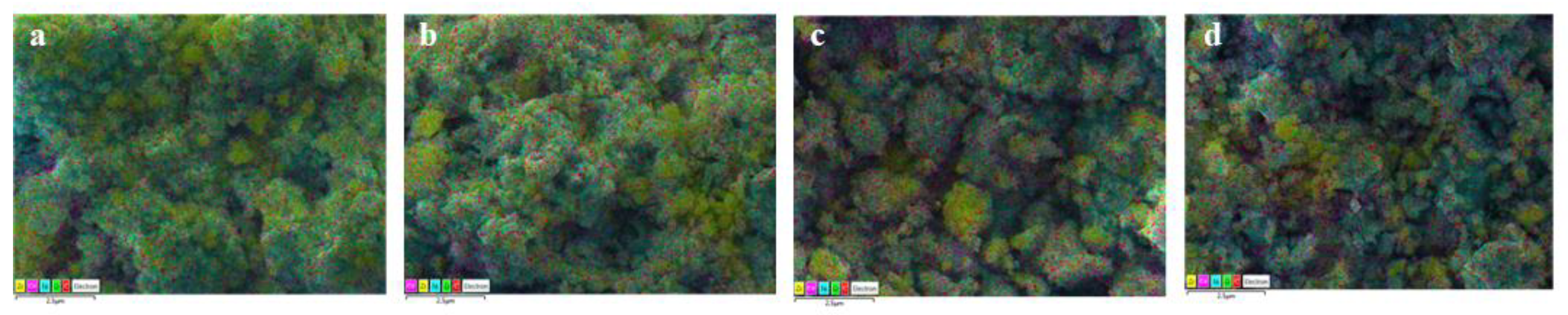
3.4. Result of Durability Test & Analysis of Catalysts

To evaluate the durability of the catalysts, this study conducted a lifetime test when 5–15% CO gas coexisted during the CO2 methanation reaction. At 300 °C as a temperature range the reaction proceeded stably which is moderate to operate in the actual process, COx methanation was observed for 24 h under each condition (Figure 9). It showed high activity and excellent stability during the 24 h COx methanation reaction.
Therefore, EDS and XRD were analyzed to observe the catalyst surface and structure after a 24 h COx methanation reaction. EDS(Scanning Electron Microscopy) mapping and point analysis were conducted to observe the surfaces after 24 h of prolonged catalytic reaction, and the results are shown in Figure 10 and Table 3. As a result of EDS mapping analysis, the elements C, O, Ni, Zr, and Ce were qualitatively analyzed for all the catalysts A to D Through EDS point analysis, the content of elements is as shown in Table 3, and there was no significant difference in the content among the samples, as the amount of carbon on the surface was 11.31–14.8%. In addition, the Ni elements exposed on the surface were 53.77–54.99 in all of A to D, and it is considered that no loss occurred during the reaction. The XRD analysis results of A-D are shown in Figure 11. Ni, ZrO2, and CeO2 diffraction peaks were observed for all catalysts. It is observed that the intensity and width of the XRD diffraction peaks of the catalysts are similar. This indicates that there is no sintering in the reaction of the catalyst particles.
From the above results, Deactivation factors such as carbon deposition or sintering were not observed. It means that the catalyst is chemistry and structural stable before and after the reaction. It seems to show stable activity in the lifetime test because of the relatively low reaction temperature of 300 °C, appropriate inter-actions between the highly dispersed Ni, the active metal, and the supporter [36] for all the catalysts under A–D conditions.

4. Conclusions

The catalytic activity for CO2 methanation was observed when CO gas coexisted in the inlet gas, and research was conducted to increase the CH4 yield in the final output gas. In summary, the following conclusions were drawn.
1. During the CO2 methanation reaction, CO2 and CO conversions were ob-served by adjusting the CO concentration in the input gas (CO2 + H2) to 0–15%. First, the CO conversion showed high methanation at 98–99%, but the CO2 conversion decreased as the CO gas concentration of the inlet gas increased. From the above results, it was observed that CO and H2 reacted first, and then CO2 reacted with H2. This part results of this study were similar to those of other previous studies.
2. After the CO2 methanation reaction, to increase the CH4 yield of the output gas, the inlet gas conditions were adjusted by calculating the volume ratio of H2:CO2 = 4:1 and H2:CO = 3:1, and then the methanation reaction was observed at 350–200 °C. High conversion was observed as the temperature decreased, and CO conversion showed a high conversion rate of more than 97% in the entire temperature range. Therefore, when CO2 is removed at the later stage of the process, it is expected that is high-quality SNG through appropriate post-processing, and the operation results will be used as important data for the development of the SNG process.
3. Activity observation and surface analysis were performed to evaluate the durability of the catalyst when CO gas coexisted in the inlet gas for a long time during the CO2 methanation reaction. As a result, stable catalytic efficiency was observed for a long time. Thus, it seems that sintering and coke did not occur under low-temperature conditions and appropriate interaction between highly dispersed Ni, the active metal, and the support occurred, showing stable activity even in a longtime test.
4. In actual processes where unexpected events such as inflow of poison gas and fluctuations in inflow flow rate occur, it is required not only to operate at an appropriate temperature but also to operate with different ratios of inflow gas. That is, in the process above the pilot, it is necessary to build a scenario suitable for the situation, not the optimal operating conditions.

Supplementary Materials

The following supporting information can be downloaded at: https://www.mdpi.com/article/10.3390/pr11020628/s1, Figure S1: Equilibrium conversion and CH4 selectivity.

Author Contributions

Conceptualization, J.A. and W.C.; methodology, J.A. and W.C.; validation, J.A.; formal analysis, J.A.; investigation, J.A.; data curation, W.C.; writing—original draft preparation, J.A.; writing—review and editing, W.C.; supervision, W.C. All authors have read and agreed to the published version of the manuscript.

Funding

This work was supported by the National Research Foundation of Korea (NRF). Grant was funded by the Korean government (MSIT) (No. 2020R1G1A1101852).

Data Availability Statement

Not applicable.

Acknowledgments

This work was supported by a National Research Foundation of Korea (NRF) and grant was funded by the Korean government (MSIT) (No. 2020R1G1A1101852).

Conflicts of Interest

The authors declare no conflict of interest.

References

  1. Masson-Delmotte, V.; Zhai, P.; Pörtner, H.O.; Roberts, D.; Skea, J.; Shukla, P.R. Summary for Policymakers. In Global Warming of 1.5 °C.; IPCC: Geneva, Switzerland, 2018. [Google Scholar]
  2. Martin, P.; Osvaldo, C.; Jean, P.; Paul, V.D.L.; Clair, H. The Fourth Assessment Report Climate Change 2007; Cambridge University Press: Cambridge, UK, 2007; pp. 8–12. [Google Scholar]
  3. Shin, M.S.; Kim, Y.J.; Lee, Y.G.; Jang, D.S. Numerical study on the co-burning of pulverized coal and stoichiometric mixture gas of hydrogen and oxygen for the reduction of CO2. J. Korea Soc. Waste Manag. 2016, 33, 1–9. [Google Scholar] [CrossRef]
  4. Climate Change 2014 Synthesis Report, UNEP. 2014. Available online: https://www.ipcc.ch/site/assets/uploads/2018/05/SYR_AR5_FINAL_full_wcover.pdf (accessed on 15 February 2023).
  5. Kuznecova, I.; Gusca, J. Property based ranking of CO and CO2 methanation catalysts. Environ. Clim. Technol. 2019, 128, 255–260. [Google Scholar]
  6. Lee, J.H.; Lee, D.W.; Jang, S.G.; Kwak, N.S.; Lee, I.Y.; Jang, K.R.; Choi, J.S.; Shim, J.G. Estimating CO2 emission reduction of non-capture CO2 utilization (NCCU) technology. Korean Chem. Eng. Res. 2015, 53, 590–596. [Google Scholar] [CrossRef] [Green Version]
  7. Wei, Z.; Hiroshi, M.; Hiroyuki, T.; Koichi, I.; Koyo, N. Computational fluid dynamics simulation of CO2 methanation in a shell-and-tube reactor with multi-region conjugate heat transfer. Chem. Eng. Sci. 2020, 211, 115–276. [Google Scholar]
  8. Irene, C.M. Carbon Dioxide Methanation for Intensified Reactors. Master’s Dissertation, Aalto University, Espoo, Finland, 2015. [Google Scholar]
  9. Yamasaki, M.; Habazaki, H.; Yoshida, T.; Akiyama, E.; Kawashima, A.; Asami, K.; Komori, M.; Shimamura, K. Compositional dependence of the CO2 methanation activity of Ni/ZrO2 catalysts prepared from amorphous Ni-Zr alloy precursors. Appl. Catal. A Gen. 1997, 163, 187–197. [Google Scholar] [CrossRef]
  10. Tada, S.; Shimizu, T.; Kameyama, H.; Haneda, T.; Kikuchi, R. Ni/CeO2 catalysts with high CO2 methanation activity and high CH4 selectivity at low temperatures. Int. J. Hydrogen Energy 2012, 37, 5527–5531. [Google Scholar] [CrossRef]
  11. Salvatore, A.; Chalachew, M.; Emanuele, G.; Fabio, D.; Samir, B.; Siglinda, P.; Raffaele, P.; Centi, G. Catalytic Performance of γ-Al2O3–ZrO2–TiO2–CeO2 Composite Oxide Supported Ni-Based Catalysts for CO2 Methanation. Ind. Eng. Chem. Res. 2016, 55, 4451–4460. [Google Scholar]
  12. Frey, M.; Romero, T.; Roger, A.C.; Edouard, D. Open cell foam catalysts for CO2 methanation: Presentation of coating procedures and in situ exothermicity reaction study by infrared thermography. Catal. Today 2016, 273, 83–90. [Google Scholar] [CrossRef]
  13. Goodman, D.J. Methanation of Carbon Dioxide. Master’s Dissertation, University of California, Los Angeles, CA, USA, 2013. [Google Scholar]
  14. Götz, M.; Lefebvre, J.; Mörs, F.; McDaniel, K.; Graf, F.; Bajohr, S. Renewable Power-to-Gas: A Technological and Economic Review. Renew. Energy 2016, 85, 1371–1390. [Google Scholar] [CrossRef] [Green Version]
  15. Thema, M.; Sterner, M.; Lenck, T.; Götz, P. Necessity and Impact of Power-to-gas on Energy Transition in Germany. Energy Procedia 2016, 99, 392–400. [Google Scholar] [CrossRef] [Green Version]
  16. Jeon, H.J.; Seo, G. Introduction to Catalyst, 4th ed.; Hanrimwon: Thornleigh, Australia, 2002; pp. 217–232. [Google Scholar]
  17. Li, B.; Maruyama, K.; Nurunnabi, M.; Kunimori, K.; Tomishige, K. Temperature profiles of alumina supported noble metal catalysts in autothermal reforming of methane. Appl. Catal. A Gen. 2004, 275, 157–172. [Google Scholar] [CrossRef]
  18. Moon, D.H.; Lee, S.M.; Ahn, J.Y.; Nguyen, D.D.; Kim, S.S.; Chang, S.W. New Ni-based quaternary disk-shaped catalysts for low-temperature CO2 methanation: Fabrication, characterization, and performance. J. Environ. Manag. 2018, 218, 88–94. [Google Scholar] [CrossRef] [PubMed]
  19. Peter, S.; Luisa, F.; Stefan, K. A Short Review on Ni-Catalyzed Methanation of CO2: Reaction Mechanism, Catalyst Deactivation, Dynamic Operation. Chem. Ing. Tech. 2021, 93, 1526–1536. [Google Scholar]
  20. Ahn, J.Y.; Chang, S.W.; Lee, S.M.; Kim, S.S.; Chung, W.J.; Lee, J.C.; Cho, Y.J.; Shin, K.S.; Moon. D., H.; Nguyen, D.D. Developing Ni-based honeycomb-type catalysts using different binary oxide- supported species for synergistically enhanced CO2 methanation activity. Fuel 2019, 250, 277–284. [Google Scholar] [CrossRef]
  21. Ahn, J.Y.; Ro, Y.H.; Chang, S.W. A Study on Optimal Conditions for Organic Matter Reduction and Hydrogen Production Using Electrolysis Process. J. Trans. Korean Hydrog. New Energy Soc. 2020, 31, 546–552. [Google Scholar] [CrossRef]
  22. David, M.M.; Laura, B.V.; Jesús, M.R.; José, F.C. A study of deactivation by H2S and regeneration of a Ni catalyst supported on Al2O3, during methanation of CO2. Effect of the promoters Co, Cr, Fe and Mo. RSC Adv. 2020, 10, 16551–16564. [Google Scholar]
  23. Neubert, M.; Treiber, P.; Krier, C.; Hackel, M.; Hellriegel, T.; Dillig, M.; Karl, J. Influence of hydrocarbons and thiophene on catalytic fixed bed methanation. Fuel 2017, 207, 253–261. [Google Scholar] [CrossRef]
  24. Rönsch, S.; Schneider, J.; Matthischke, S.; Schlüter, M.; Götz, M.; Lefebvre, J.; Prabhakaran, P.; Bajohr, S. Review on methanation-From fundamentals to current projects. Fuel 2016, 166, 276–296. [Google Scholar] [CrossRef]
  25. Selina, N.; Udo, A.; Sebastian, D.; Marco, K. Recent Advances in Catalysis for Methanation of CO2 from Biogas. J. Catal. 2022, 12, 374. [Google Scholar]
  26. Witte, J.; Calbry-Muzyka, A.; Wieseler, T.; Hottinger, P.; Biollaz, S.M.; Schildhauer, T.J. Demonstrating direct methanation of real biogas in a fluidised bed reactor. J. Appl. Energy 2019, 240, 359–371. [Google Scholar] [CrossRef]
  27. Yokomizo, G.H.; Bell, A.T. Isotopic tracer and NMR studies of carbonaceous species present during CO hydrogenation over RuTiO2. J. Catal. 1989, 119, 467–482. [Google Scholar] [CrossRef]
  28. Agnelli, M.; Kolb, M.; Mirodatos, C. CO Hydrogenation on a nickel catalyst: 1. Kinetics and modeling of a low-temperature sintering process. J. Catal. 1994, 148, 9–21. [Google Scholar] [CrossRef]
  29. Agnelli, M.; Swaan, H.M.; Marquez-Alvarez; Martin, G.A.; Mirodatos, C. CO hydrogenation on a nickel catalyst: II. A mechanistic study by transient kinetics and infrared Journal Pre-proof spectroscopy. J. Catal. 1998, 175, 117–128. [Google Scholar] [CrossRef]
  30. Kiewidt, L.; Thoming, J. Predicting optimal temperature profiles in single-stage fixed-bed reactors for CO2-methanation. Chem. Eng. Sci. 2015, 132, 59–71. [Google Scholar] [CrossRef]
  31. Stangeland, K.; Kalai, D.; Li, H.; Yu, Z. CO2 Methanation: The Effect of Catalysts and Reaction Condition. Energy Procedia 2017, 105, 2022–2027. [Google Scholar] [CrossRef]
  32. Xu, S.; Chansai, S.; Xu, S.; Stere, C.; Jiao, Y.; Yang, S.; Hardacre, C.; Fan, X. CO Poisoning of Ru Catalysts in CO2 Hydrogenation under Thermal and Plasma Conditions: A Combined Kinetic and Diffuse Reflectance Infrared Fourier Transform Spectroscopy−Mass Spectrometry Study. ACS Catal. 2020, 10, 12828–12840. [Google Scholar] [CrossRef]
  33. Schmider, D.; Maier, L.; Detuschmann, O. Reaction Kinetics of CO and CO2 Methanation over Nickel. IEC Res. 2021, 60, 5792–5805. [Google Scholar] [CrossRef]
  34. Burger, T.; Donaubauer, P.; Hinrichsen, O. On the kinetics of the co-methanation of CO and CO2 on a co-precipitated Ni-Al catalyst. Appl. Catal. B Environ. 2021, 282, 119408. [Google Scholar] [CrossRef]
  35. Jan, K.; Tilman, J.S.; Serge, M.A.B. Production of synthetic natural gas (SNG) from coal and dry biomass—A technology review from 1950 to 2009. Fuel 2010, 89, 1763–1783. [Google Scholar]
  36. Lu, X.; Gu, F.; Liu, Q.; Gao, J.; Liu, Y.; Li, H.; Jia, L.; Xu, G.; Zhong, Z.; Su, F. VOx promoted Ni catalysts supported on the modified bentonite for CO and CO2 methanation. Fuel Process. Technol. 2015, 135, 34–46. [Google Scholar] [CrossRef]
Figure 1. Schematic diagram of power to gas plant with CO2 methanation.
Processes 11 00628 g001
Figure 2. Trend of CO2 methanation research according to Year (left) and The fields of CO2 methanation studied over the last 10 years (2012–2022) (right).
Processes 11 00628 g002
Figure 3. Schematic diagram of CO2 methanation reactor.
Processes 11 00628 g003
Figure 4. The effect on activity according to CO gas concentration (0–15%) in the CO2 methanation reaction.
Processes 11 00628 g004
Figure 5. The composition of gases produced according to CO gas concentration (0–15%) in the CO2 methanation reaction (1): (a) non-co (b) with CO 5% (Total inlet gas 120 mL/min).
Processes 11 00628 g005
Figure 6. The composition of gases produced according to CO gas concentration (0–15%) in the CO2 methanation reaction (2): (c) with CO 10% (d) with CO 15% (Total inlet gas 120 mL/min).
Processes 11 00628 g006
Figure 7. Result of COx methanation: At the ratio of inlet gases H2:CO2 = 4:1 to H2:CO = 3:1.
Processes 11 00628 g007
Figure 8. The concentration of the final out gases after the methanation reaction depending on reaction temperatures (Inlet gas ratio: H2:CO2 = 4:1 to H2:CO = 3:1).
Processes 11 00628 g008
Figure 9. Result of a prolonged COx methanation reaction at 300 °C.
Processes 11 00628 g009
Figure 10. Composition of catalysts from EDS mapping.
Processes 11 00628 g010
Figure 11. XRD patterns of the (a–d) catalysts.
Processes 11 00628 g011
Table 1. Composition of by-product gases and biogases.
By-Product GasesBiogases
*COG**LDG***BFGSewage
Sludge
Livestock
Manure
Food Waste
H210–56.4%0–4%0.2–3.2%
CO23–9%20–22%20–23.2%30–40%25–35%20–35%
CO8.4–16%64–65%20–23%
N22–20%17–22%45.6–54%
CH436–37% 55–65%60–70%60–75%
C2H43%
O20.3%
H2O 3–5%3–5%3–5%
Impurities H2S
Siloxane
H2S
Siloxane
H2S
Siloxane
*COG: Coke Oven Gas; **LDG: Linze Donawitz Gas; ***BFG: Blast Furnace Gas.
Table 2. Types of samples analyzed by EDS, XRD.
Nameabcd
Experiment conditionswith CO 0%with CO 5%with CO 10%with CO 15%
Note: Reaction gas for CO2 methanation: 4H2 + CO2 + (A–D conditions).
Table 3. Composition of catalysts from EDS Point.
Elementabcd
C13.0314.811.3113.11
O10.8810.410.2911.26
Ni54.9955.9653.9153.77
Zr4.86.166.276.09
Ce16.312.7818.2215.77
Total atom (%)100100100100
Disclaimer/Publisher’s Note: The statements, opinions and data contained in all publications are solely those of the individual author(s) and contributor(s) and not of MDPI and/or the editor(s). MDPI and/or the editor(s) disclaim responsibility for any injury to people or property resulting from any ideas, methods, instructions or products referred to in the content.

