Article

Flow Control in Multiphase Pumps Based on Separated Trailing Edge Flap

School of Energy and Power Engineering, Lanzhou University of Technology, Lanzhou 730050, China
*
Author to whom correspondence should be addressed.
Processes 2023, 11(11), 3066; https://doi.org/10.3390/pr11113066
Submission received: 26 September 2023 / Revised: 18 October 2023 / Accepted: 20 October 2023 / Published: 26 October 2023
(This article belongs to the Special Issue Design and Optimization Method of Pumps)

Abstract

:
In developing and transporting significant oil fields in deep-sea environments, multiphase pumps are considered crucial energy conversion equipment. Ensuring their safe, efficient, and stable operation is currently a primary focus of research. The intermittent aggregation of the gas phase at the trailing edge flap of the impeller blades in multiphase pumps can lead to periodic and significant fluctuations in flow rate and outlet pressure, posing a threat to the overall operational safety of the pump system. Based on aerodynamic principles, this paper presents the design of a separate trailing edge flap for the impeller blades. The inner nodal method is applied to determine the design scheme of the trailing edge flap for the multiphase pump. A numerical approach is employed to analyze the impact of the flap deflection angle on the internal flow characteristics to provide theoretical guidance for the structural optimization of multiphase pumps. The results indicate that the influence of the deflection angle on the pump efficiency is complex and affected by a critical angle value. When the deflection angle is below the critical value, the trailing edge flap can effectively reduce the formation of energy dissipation vortices and radial pressure gradients within the impeller channel, enabling a significant improvement in the gas-phase aggregation phenomenon caused by gas–liquid separation. However, additional energy losses occur at the connection between the trailing edge flap and the main blade body for deflection angles exceeding the critical value. When the trailing edge flap length is 0.25 l and the deflection angle is 5°, the efficiency is improved by 3.4% compared to the original model. Consequently, the pressurization capacity of the pump is compromised. In the design and application of trailing edge flaps, a careful balance between various factors is required to ensure both the stability and high efficiency of the pump system.

1. Introduction

To ensure that non-renewable energy sources, such as oil and gas, support economic development and energy security for people’s production and lives, various countries have shifted the goal of oil and gas resource development from the land to the resource-rich marine field [1,2]. It sets higher standards and requirements for oil and gas production technology due to the complex and variable environment of deep-sea oil and gas reserves. Multiphase pumps in oil and gas production systems are considered critical energy conversion devices essential for improving oil fields’ production rate and economic efficiency [3,4,5].
The helical-axial multiphase pump enables the multiphase fluid passing through the high-speed rotating impeller to acquire kinetic energy [6,7,8]. Then, it relies on the pressurizing capacity of the guide vane to allow the liquid to realize the conversion of kinetic energy to pressure energy. In practice, due to the different densities of gas and liquid, the conveying medium will be subjected to varying centrifugal forces as the impeller rotates, causing a series of flow disturbances such as flow separation, gas stagnation, and pressure surge [9,10]. These phenomena cause a sharp increase in the flow losses of the pump components and thus lead to a sharp decline in pump performance and efficiency. Therefore, to ensure the high efficiency and safety of multiphase pumps in energy utilization, the exploration of their flow field instability and flow mechanisms holds significant theoretical and engineering importance. Numerous research institutions and university laboratories have already undertaken extensive research in this field. Wang et al. [11] have pointed out that five interfacial forces at the gas–liquid two-phase interface, including drag force, lift force, virtual mass force, wall lubrication force, and turbulent dispersion force, play a significant role in the analysis of multiphase pump flow simulation. Among these, the influence of drag force significantly surpasses that of other forces. Furthermore, Xu Y et al. [12] conducted experimental research on the internal characteristics of multiphase pumps and monitored the transient pressure field. The study revealed that the relative motion and separation of the two phases led to significant pressure fluctuations. Shi et al. [13], by employing a combined approach of numerical simulation and experimentation, investigated the internal flow characteristics of a newly designed three-stage multiphase transfer pump, considering the influence of different turbulence models, bubble diameters, and interphase drag coefficients. Wang et al. [14] combined visual experiments with transient numerical simulations to explore flow pattern issues of multiphase transfer pumps at various gas fractions, and they applied entropy production theory to analyze energy losses under different flow patterns.
However, the gas–liquid two-phase flow instability inside the multiphase pump not only affects the pump’s hydraulic performance but also threatens the safety and reliability of the whole oil and gas mixing system under a specific gas content rate [15]. As an indispensable part of the multiphase pump, the impeller can be studied and improved to enhance the performance of the pump. Xiao and Tan [16] proposed a controlled velocity moment design method to optimize the impeller of a multiphase pump, which not only led to a reduction of transient pressure pulsations in the pump but also improved the pump head and efficiency to a large extent. Liu et al. [17] proposed a design method that can predict the diffuser’s velocity moment, optimize the inlet angle of the lower-stage impeller, and apply it to a three-stage multiphase mixed transfer pump. The results show that the dynamic–static interaction and gas–liquid two-phase interaction in the pump are successfully suppressed under the optimal distribution of velocity moments. Peng et al. [18] adopted an adaptive refined response surface method and applied it to optimize the design parameters of the impeller and guide vane of the multiphase pump. This method selects the optimal model from the perspective of three adaptive response surfaces. It then uses the MOGA (Multi-Objective Genetic Algorithm) method to obtain the optimized response surface model; the enhanced capacity of the optimized model has been significantly improved.
A great deal of previous research has been on optimizing multiphase pumps, focused on theoretical studies. However, there are few kinds of research specifically aimed at optimizing the modification of the impeller structure. Patone et al. [19] were the first to locate adaptive flaps similar to bird feathers on the trailing edge flap of a blade’s suction surface to investigate their effect on flow separation control. It was found that lifting the trailing edge flaps at a certain angle can effectively increase the lift and stop the further development of flow separation. After that, the trailing edge flap based on bionics has been widely used in the fields of aviation and fluid mechanics, and many domestic and foreign scholars have conducted in-depth research on its structure and performance [20]. Jawaha et al. [21] conducted an experimental and numerical simulation study on the air-foil of the NACA 0012 flap with a deformed trailing edge flap. They investigated the effect of different flap curvatures on the aerodynamic flow structure, boundary layer, and shear stresses. Feszty et al. [22] computationally analyzed the interaction mechanism between trailing edge flaps and dynamic stall vortex by the CFD numerical simulation method. They found that an optimal flap structure can effectively reduce the negative pitching moment and damping. Through the research on trailing edge flapping by scientists in each field above, it has been found that the deformed trailing edge flap structure represents an advantageous passive flow separation control method. This approach not only boasts structural simplicity but also has the ability to enhance lift, ameliorate airfoil dynamic stall issues, and, to a certain extent, alleviate separation phenomena on the suction side [23,24]. Therefore, an effective way to optimize the performance of fluid mechanics is to use trailing edge flaps.
This study refers to the basic principle of controlling the inverse pressure gradient at the trailing edge of the blade grille based on the trailing edge flap to investigate the effect of multiphase pump impeller blade trailing edge flaps on the degree of separation of gas–liquid two-phase fluids and the degree of gas phase stagnation. The impact of the blade trailing edge flap’s relative chord length and deflection angle on the reverse pressure gradient before and after the gas phase vortex cluster under different initial gas phase volume fractions is examined. In order to provide theoretical guidance for the optimal design of multiphase pump performance.

2. Numerical Models and Methods

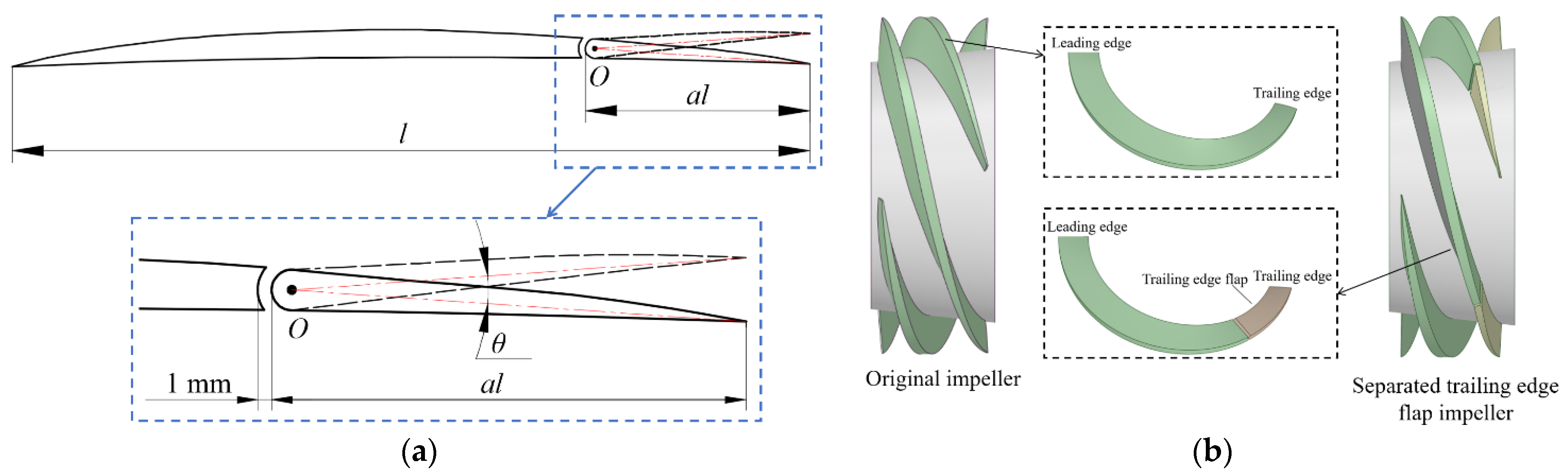
2.1. Geometric Models

A single compression unit of a helical-axial multiphase pump was selected for the study, The design parameters and the final structural parameters are shown in Table 1. Figure 1 shows the schematic views of the impeller. The computational domain is established by SolidWorks 2010 3D modeling software, which includes inlet section, impeller, guide vane, and outlet section, as shown in Figure 2.

2.2. Mesh Generation

Structured meshing of the computational domain was performed using the commercial software ICEM CFD 16.0 and TurboGrid 16.0. The boundary layer is arranged close to the wall, the total number of layers of the boundary layer mesh is 13, the height of the first layer of the mesh is 0.06 mm, and the growth rate is set as 1.2; the Y+ of the guide vane and impeller blade surface is less than 30, which basically meets the computational requirements of the SST k-ω turbulence model [25,26], and the computational domain mesh is shown in Figure 2.
To avoid the influence of the number of grids on the computational results, six sets of grids with different numbers are used for grid-independent verification. Grid irrelevance was judged by reaching a stabilized value of the multiphase pump head at the designed flow rate and inlet gas volume fraction of 50%. Figure 3 shows that the head deviation is 0.05% when the number of grids is more significant than 4328312. Considering the numerical simulation accuracy and computational resources, the total number of grids in the whole computational domain is determined to be 4328312.

2.3. Governing Equations and Numerical Settings

Considering the relatively high gas volume fraction in multiphase pumps and the immiscibility of the gas–liquid phases, a numerical simulation is conducted using the Eulerian–Eulerian non-homogeneous phase flow model. It is assumed that the flow pattern of the gas–liquid two-phase flow is a bubbly flow, which satisfies mass and momentum conservation [27]. The governing equations for the temperature field are not considered and are as follows:
Continuity equation:
t ( α i ρ i ) + ( α i ρ i u i ) = 0
Momentum equation:
t ( α i ρ i u i ) + ( α i ρ i u i u i ) = α i p i + ( α i μ i ( u i + u i T ) ) + M i + α i ρ i f i
where the subscript i = l or g represents the liquid or gas phase; ρi is the density; αi is the volume fraction of the i phase; ui is the velocity vector of the i phase; μi is the dynamic viscosity of the i phase; Mi is the interphase force of the i phase; fi is the mass force related to impeller rotation; and the gas–liquid two-phase relationship is αl + αg = 1.
The SST k-ω turbulence model is applied to solve the Reynolds-averaged control equations for better capturing of flow separation phenomena in multiphase pumps [28]. The equations are as follows:
( ρ k ) t + ( ρ k u l ) x i = P k β * ρ k ω + x j [ ( μ + μ t σ k 1 ) k x j ]
( ρ ω ) t + ( ρ ω u l ) x i = x j [ ( μ + μ t σ ω 1 ) ω x j ] + α 1 ω k P k β ρ ω 2 + 2 ( 1 F 1 ) ρ 1 ω σ ω 2 k x j ω x j
where β* = 0.09, σk1 = 2, σω1 = 2, α1 = 5/9, β = 0.075, F1 is a mixed function, and μt is the turbulent viscosity, defined as follows:
μ t = ρ a 1 k max ( a 1 ω , S F 2 )
where a1 = 0.31, F2 is a blending function that restricts the limiter to the wall boundary layer, and S is an invariant measure of the strain rate.
The steady-state simulation of multiphase pump flow field employs ANSYS FLUENT 2016 [29,30]. The finite volume method is employed to discretize the system of control equations. For the convective terms, a second-order upwind scheme is used. The SST k-ω turbulence model is used in the liquid phase, and the discrete phase zero equation model is used in the gas phase. The boundary conditions are set to velocity inlet and pressure outlet, the no-slip boundary condition is used for the solid wall, and the convergence accuracy is set to 10−5; the Phase Coupled SIMPLE algorithm is used to solve the coupling problem of pressure and velocity. The multiple reference frame model is used for simulation, where the impeller is set as the rotating domain, and all other computational domains are designated as stationary domains. The data transfer between the rotating and stationary domains is carried out through the interface surface.

2.4. Experiment Verification

The structure of the test bench for the test system of the helical-axial flow multiphase pump is shown in Figure 4, which is mainly composed of liquid and gas pipelines. The liquid and gas are supplied by the medium-pressure tank and air compressor, respectively, to regulate the liquid flow through the liquid regulating valve and flow meter and to regulate the gas flow into the pipeline through the airflow meter and air regulating valve. The pump head, (gas–liquid) flow rate, and shaft power are measured using inlet and outlet differential pressure gauges, electromagnetic flow meters, air flow meters, and speed and torque meters. The experiments are conducted at room temperature (25 °C), with the inlet absolute pressure of the pump maintained at a constant 0.5 MPa. The main measuring instrument parameters of the test bench are shown in Table 2.
To assess the reliability of the experimental results for the multiphase pump, a comprehensive uncertainty analysis (Ucom) is conducted for all measured parameters. The comprehensive uncertainty is composed of both random uncertainty (Uran) and systematic uncertainty (Usys). The Uran for liquid flow rate Ql, gas flow rate Qg, head H, torque T, and rotational speed n is calculated by conducting five experiments at the designed flow point and 50% inlet gas fraction using the Student T-type distribution. Usys is related to the precision of the measurement instruments, and the relevant data are provided in Table 2. The combined uncertainty (Ucom) for each component is calculated as the square root of the sum of the squares of random uncertainty and systematic uncertainty. The comprehensive uncertainties for inlet gas fraction, head, and efficiency in this case are ±0.74%, ±0.62%, and ±1.22%, respectively. The detailed calculations are presented in Table 3.
This numerical simulation method is verified based on different flow conditions at IGVF = 50%. Figure 5 shows the comparison of the external characteristic curves of the two-phase numerical simulation and experiment. As can be seen from the figure, the curves for different flow conditions have a consistent trend, and the relative deviation between head and efficiency is between 5% and 10%. Owing to the complexity and unpredictability of the gas–liquid two-phase flow, there are inevitable friction loss and hydraulic loss errors between its experimental and numerical simulation results. Therefore, numerical simulations and experiments have an error of 10% or less at the designed flow point, which is within acceptable limits.

3. Design Schemes

Figure 6 illustrates how to define a separated trailing edge flap. The separated trailing edge flap and the original model are airfoil 791, with the airfoil chord length defined as l. Separated trailing edge flaps are created at al from the trailing edge of the airfoil. The gap between the trailing edge flap and the main body of the airfoil is designed as a rounded structure. The gap width is 1 mm. The trailing edge flap can be deflected in the direction of the suction plane around point O; the deflection angle is defined as θ.
To more accurately design separated trailing edge flap blades with excellent transport performance, it is necessary to explore the locations where gas-phase fluid media accumulate and block the flow channel specifically. The location of the gas-phase aggregation in the original model’s impeller channel is analyzed using the finite volume method. In the case of multiphase pumps transporting gas-liquid two-phase fluid medium, the gas-phase medium tends to aggregate significantly near the impeller hub and at the outlet of the flow passage. Therefore, the analyzed area is set as the back half of the 0.1-times blade height development surface of the impeller channel of the multiphase pump; e is the axial length of the impeller at 0.1 times the height of the blade, i.e., 0.5e~1.0e of the axial length. As shown in Figure 7, the 0.5e~1.0e region was divided into areas at 0.1e intervals, and the gas phase aggregation in each area was analyzed.
The gas-phase aggregation distribution rate is calculated by the inner node method by screening and summing the area of the grids with a gas-phase volume fraction greater than 0.8 in every 0.1e region, and then comparing its area with the total area of the grids with gas-phase volume fraction greater than 0.8 in the region of 0.5e~1.0e to derive the gas-phase aggregation distribution rate, which reflects the specific distribution of the gas-phase aggregation. The main idea of the inner node method is to divide the computational domain into a series of non-overlapping control volumes, with nodes located at the centers of these control volumes. Physical parameters are stored at these nodes and used to discretely represent and solve partial differential equations. We define the gas-phase aggregation distribution ratio ε, represented as follows:
ε = S ( k 1 e < x k 2 e , G V F > 0.8 ) S ( x > 0.5 e , G V F > 0.8 ) × 100 %
where k1 and k2 are taken from 0.5 to 1, k2 > k1.
From the data in Figure 8, it is apparent that the distribution of air blocks in the impeller channel is more consistent under different inlet gas volume fractions. More than 80% of the gas-phase aggregates at different inlet gas volume fractions are in the range of 0.7e~1.0e, which corresponds to the flow channel at the position of 70~100% of the chord length of the multiphase pump blade according to the similarity triangle rule.
Through the analysis described above, when conveying gas–liquid two-phase media, the gas phase in a multiphase pump is concentrated in the last 30% of the chord length of the flow channel. Therefore, the length of the separated trailing edge flaps was set to (0.10–0.30) l, with a taking values in the range of 0.10–0.30 and 0.05 between each scheme. According to Patone et al. [19], it is known that the trailing edge flaps can effectively prevent flow separation at certain angles. The deflection angle θ was set between 0° and 8°. The angle interval between each scheme was 1°. In this research, only the 15 schemes in Table 4 are analyzed and discussed at the designed flow rate and five different inlet gas volume fraction conditions.

4. Results

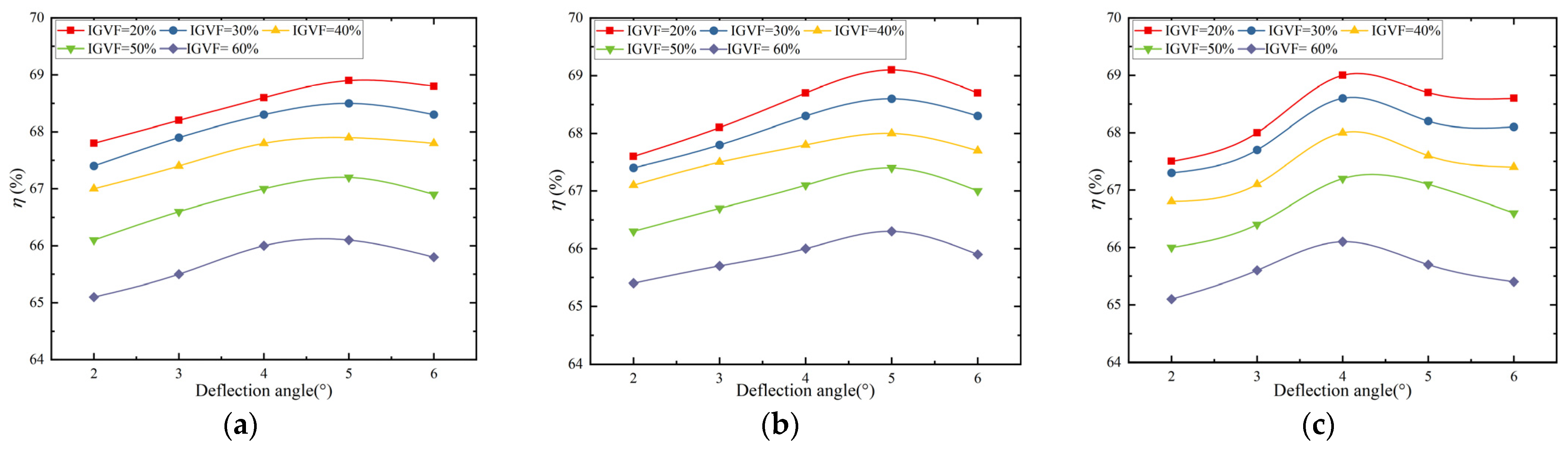
4.1. Hydraulic Performance Analysis

Figure 9 and Figure 10 illustrate the external characteristic curves of the multiphase pump under different deflection angles and flap lengths (0.20 l, 0.25 l, and 0.30 l). It can be observed that as the inlet gas volume fraction increases, the efficiency and head of the different schemes exhibit a decreasing trend, consistent with the variation pattern of the original model. When the length of the trailing edge flap remains constant, the efficiency of the multiphase pump shows an increasing trend followed by a decreasing trend as the deflection angle increases, with an optimal efficiency point. When the trailing edge flap length is between 0.20 l and 0.25 l, the pump’s optimal efficiency point corresponds to an angle of deflection of 5°. In these cases, the efficiency at a 50% inlet gas fraction increased by 2.85% and 3.40%, respectively, compared to the original model. However, when the trailing edge flap length is 0.30 l, the pump’s optimal efficiency point corresponds to a 4° deflection angle, resulting in a 2.71% improvement in efficiency compared to the original model at a 50% inlet gas volume fractions. Under different lengths of the trailing edge flap, the head continuously decreases with an increasing deflection angle. The reason for this phenomenon is that the deflection of the trailing edge flap towards the suction surface reduces the curvature of the original airfoil, thereby decreasing the blade’s pressure-raising performance and resulting in a decrease in the pump’s head.
It has been observed that the utilization of separate trailing edge flaps can enhance conveying efficiency while examining the external characteristics of multiphase pumps across various schemes. However, it is essential to acknowledge that the internal multiphase flow within rotating machinery is an exceedingly intricate process. The critical factor for the enhanced delivery efficiency of the multiphase pump, achieved through the implementation of separated trailing edge flaps, lies in the amelioration of the internal flow. Consequently, conducting a comprehensive analysis of how the internal flow works plays a vital role in this. Although the trends in external characteristics remain largely consistent for different deflection angles with the same flap length, the overall performance of the trailing edge flap measuring 0.25 l surpasses other schemes, particularly under the condition of IGVF = 50%. In light of this, the subsequent discourse will concentrate on scrutinizing the internal flow mechanism of the scheme featuring a trailing edge flap length of 0.25 l and a deflection angle ranging from 2° to 6°.

4.2. Internal Flow Characteristics of the Multiphase Pump with Trailing Edge Flap Length of 0.25 l

4.2.1. Gas-Phase Distribution Law

Figure 11 illustrates the gas-phase distribution at 0.1 times the blade height within the impeller channel when the trailing edge flap length is 0.25 l and the deflection angle ranges from 2° to 6°. As shown in the figure, a comparison with the original model reveals that within the impeller channel of the trailing edge flap scheme, the gas phase accumulates predominantly in the region of the trailing edge on the suction side of the blade. However, there is a discernible improvement in the extent of gas-phase accumulation. With an increase in the deflection angle, the range of gas-phase accumulation near the trailing edge on the suction side of the blade gradually diminishes.
Moreover, gas-phase accumulation exists within the gaps of the trailing edge flap. This phenomenon arises because, upon the deflection of the trailing edge flap towards the suction side, the reduced pressure differential between the pressure and suction sides hinders the establishment of gas-phase medium flow. This causes the gas-phase medium to linger within the gaps, consequently mitigating blockage within the impeller channel. Nonetheless, when the deflection angle becomes overly large, the region adjacent to the trailing edge flap gap on the pressure side of the blade might incur gas-phase congregation.

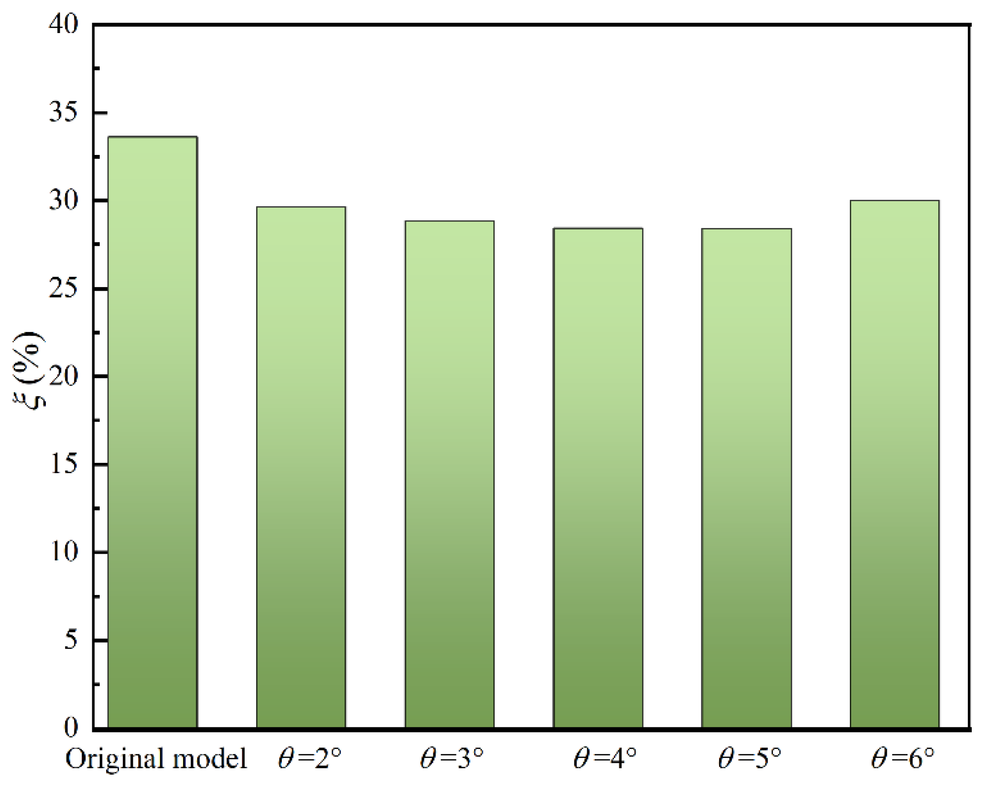
4.2.2. Energy LOSS characteristics

Figure 12 shows the gas-phase streamlines diagram at 0.1 times the blade height of the impeller channel for a trailing edge flap length of 0.25 l and a deflection angle θ = 2°~6°. Within the original model, a pronounced dissipation vortex is observed at the trailing edge of the suction side of the blade, as shown by the red circle in the diagram. This phenomenon corresponds with the region of the highest gas-phase accumulation at this location. This observation clarifies that when the gas phase medium accumulates to a certain extent, it triggers the formation of dissipation vortices. This dissipative vortex is generated due to the flow instability of the gas–liquid two-phase flow. The instability and energy transfer of the vortex structure itself can result in a significant energy loss in the impeller channel. With a constant trailing edge flap length, when θ = 3°, there is only a small amount of energy dissipation. As the deflection angle progressively increases, the dissipation vortex structure at the trailing edge of the suction side of the blade dissipates. This demonstrates that increasing the deflection angle of the trailing edge flap can effectively enhance the flow state of the gas-phase fluid medium.
Figure 13 shows the cloud diagram of turbulent kinetic energy distribution in the impeller meridian surface at a trailing edge flap length of 0.25 l and a deflection angle of θ = 2°~6°. The distribution of turbulent kinetic energy visually reflects the internal flow losses in multiphase pumps with different blade structures. In the region of the impeller inlet, proximate to both the hub and shroud regions, there is a substantial gradient variation in turbulent kinetic energy. This is because the multiphase medium substantially impacts the blades and impeller walls when flowing into the impeller, causing the flow state in this region to become turbulent, resulting in partial energy loss. In the middle channel of the inlet, a notable region of heightened turbulent kinetic energy exists. This occurrence can be attributed to the dissimilarity in the physical properties of the multiphase medium. Once the medium enters the impeller, the distinct phases experience varying force interactions, giving rise to gas–liquid separation phenomena. This, in turn, leads to a disturbed flow state in the region.
In the original model, a notable region of heightened turbulent kinetic energy exists near the hub in the region of the outlet of the passage. This region corresponds to the previously discussed region of gas phase accumulation and dissipation vortices. In the trailing edge flap schemes, the significant region of high turbulent kinetic energy at this location is notably diminished. This indicates that the trailing edge flap effectively reduces the magnitude of dissipation vortices, subsequently curbing the dissipation of fluid-medium kinetic energy. However, when the deflection angle of the trailing edge flap becomes excessively large, the fluid medium tends to generate impacts near the junction of the trailing edge flap and the main body of the blade, resulting in additional energy losses.
To precisely analyze the energy dissipation across various deflection angle schemes of the trailing edge flap within the impeller channel and to effectively assess the dual positive and negative impacts of the deflection angle on energy losses, the concept of energy dissipation coefficient ξ is introduced. The magnitude of energy dissipation ξ reflects the degree of energy loss of the fluid medium in the analyzed region. This metric quantifies the degree of energy loss in the fluid medium over the analyzed region, leading to a better understanding of the flow characteristics. The expression is as follows:
ξ = S T K E > 0.5 S T K E × 100 %
where STKE is the total grid area of the analysis area and STKE>0.5 is the grid area with turbulent kinetic energy greater than 0.5.
Figure 14 shows that the energy dissipation coefficients of the trailing edge flap schemes are consistently lower than those of the original model. This observation indicates that the deflection of the trailing edge flap reduces the dissipation vortex at the trailing edge on the suction side of the blade, consequently diminishing energy losses. This decrease in energy losses outweighs the energy losses incurred due to the deflection-induced impact. Notably, the energy dissipation coefficient is lowest at a deflection angle of 5°, corresponding to the highest efficiency of the multiphase pump.
When considering the results from both Figure 9, Figure 10 and Figure 11, it is evident that deflection angles of 3° and 4° notably lessen the extent of gas-phase accumulation at the trailing edge of the suction side of the blade. However, as the deflection angles are relatively small, the complete elimination of gas-phase accumulation-induced blockages within the impeller channel remains incomplete. A deflection angle of 6° effectively improves the degree of gas-phase accumulation at the trailing edge of the suction side of the blade. However, due to the excessive deflection angle, not only does the pressure side of the blade near the trailing edge flap witness the accumulation of gas-phase fluid medium, but it also subjects the blade to fluid-medium impact, consequently introducing new energy dissipation. Therefore, the energy dissipation at a deflection angle of 6° is slightly higher than at 5°.

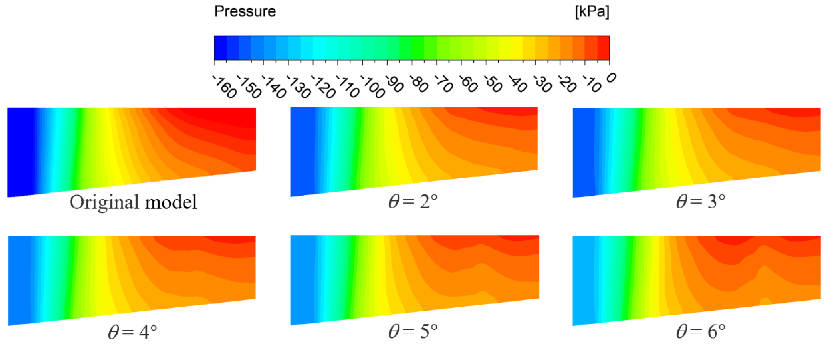
4.2.3. Pressure Distribution Laws

To explore the influence of altering the deflection angle of the trailing edge flap on the degree of gas–liquid separation within the impeller channel, an analysis of the pressure distribution along the meridional plane of the impeller channel is conducted. This investigation seeks to elucidate variations in the radial pressure gradient under different scenarios. Figure 15 presents contour plots of the pressure distribution along the meridional plane for both the original model and the trailing edge flap scheme with a length of 0.25 l, spanning deflection angles from θ = 2° to 6° at the designed flow rate and 50% inlet gas volume fraction. Evidently, as shown in the Figure 15, the pressure distribution in the trailing edge flap scheme concurs with that of the original model. In the first half of the impeller channel, a gradual axial pressure rise results in a noticeable axial pressure gradient, owing to the rapid axial compression of the fluid. However, in the latter half of the channel, the axial pressure rise progressively becomes more gradual.
In terms of the radial direction, both the trailing edge flap scheme and the original model exhibit radial pressure gradients in the latter half of the channel. However, the former’s radial pressure gradient is smaller; the radial pressure gradient induces an acceleration of the fluid medium in the radial direction. Due to the high density differences in the gas–liquid-phase medium, a significant gas–liquid separation phenomenon is induced. As a result, the liquid-phase fluid medium with higher density moves towards the region near the shroud, while the gas-phase fluid medium with lower density moves towards the area near the impeller hub, and its flow inhomogeneity increases. In the latter half of the meridional surface, an upward convex region in the pressure gradient is observed. This phenomenon arises because the trailing edge flap begins to deflect from the blade edge at a distance of 0.25 l, thereby altering the original shape of the blade and subsequently affecting the pressure distribution within the impeller channel.
In multiphase pumps, as the flowing medium passes through the impeller channels, the work capacity of the blades increases the kinetic energy of the fluid, which generates a higher pressure at the pressure surface. This pressure differential induces a gradient between the pressure and suction sides, compelling the gas to accumulate at the suction side. Furthermore, as the fluid flows from the inlet to the outlet, pressure gradually increases in this direction, leading to a pressure gradient that causes the gas to aggregate in the flow channel towards the outlet. Hence, it is essential to study the pressure gradient in the impeller channel to improve the performance of multiphase pumps and prevent the gas phase from accumulating. A more detailed analysis of pressure data at different positions along the meridional plane of the impeller channel is conducted. This analysis is illustrated in Figure 16, where Fpr denotes the radial pressure gradient and Fpz signifies the pressure gradient along the streamline direction. The positions are labeled as follows: 0 corresponds to the inlet of the impeller channel, 0.5 represents a position at 0.5 times the axial distance from the impeller channel, and 1.0 denotes the exit of the impeller channel.
The gas–liquid separation phenomenon is the main factor affecting the performance of multiphase pumps, and when multiphase pumps are used for gas–liquid transportation, there exists a large radial pressure gradient force in the back half of the impeller channel. Therefore, by analyzing the radial pressure gradient, the improvement of the gas–liquid separation phenomenon in the impeller channel by different trailing edge flap schemes can be visualized. Therefore, an analysis is conducted on the radial pressure gradient distribution curve shown in Figure 17 for the central to outlet region of the impeller meridional plane under the condition of 50% inlet gas volume fraction: In the original model, the radial pressure gradient in the latter half of the impeller channel exhibits a trend of decreasing followed by an increase. With the introduction of the trailing edge flap, the radial pressure gradients at various positions in the second half of the impeller channel are significantly lower than in the original model. Moreover, at a deflection angle of 2°, due to the relatively small angle, the curve exhibits a flat-trend radial pressure gradient trend at the blade end (0.9–1.0), while for other angles, it shows a decreasing trend. As the deflection angle increases, the slope of the descending curve becomes larger. In addition, radial pressure gradient at the outlet of the impeller channel becomes smaller. This trend signifies that the deflection of the trailing edge flap towards the suction side effectively reduces the radial pressure gradient within the impeller channel of the multiphase pump. This alteration further mitigates the degree of separation between the gas and liquid phases of the fluid medium, thereby enhancing the multiphase pump’s performance.

4.2.4. Pressure Gradient Analysis along the Streamwise Location

Figure 18 shows the contour plots of pressure distribution at 0.1 times the blade height in the impeller channel of the multiphase pump compression unit. The study shows that different trailing edge flap schemes exhibit lower pressure gradients than the original model in the regions immediately after the trailing edge on both the suction and pressure sides of the blade, as well as at the junction of the suction and pressure sides. This indicates that the deflection of the trailing edge flap towards the suction side reduces the blade’s pressure-raising capability, contributing to a decrease in the pump’s head.
The introduction of trailing edge flaps reduces the adverse pressure gradient at the end of the impeller flow channel. This change helps to transport the gas-phase medium, which is caused by gas–liquid separation. Under a certain trailing edge flap length, with an increase in the deflection angle, the pressure difference between the suction side and pressure side of the flap gradually diminishes. This decrease effectively alleviates or prevents a sudden surge in the adverse pressure gradient near the trailing edge of the blade, thereby mitigating gas-phase retention. However, when the deflection angle becomes too large, a situation arises where the pressure on the suction side of the flap significantly surpasses the pressure on the pressure side. This could lead to partial gas-phase accumulation and stagnation on the pressure side, resulting in anomalous flow behavior.
For a more in-depth exploration of the impact of trailing edge flap deflection angle variations on the pressure gradients within the impeller channel of the multiphase pump, pressure data were extracted from both the original model and the trailing edge flap scheme with a length of 0.25 l and deflection angles θ = 2° to 6°. Pressure variation curves along the streamline direction were plotted, as illustrated in Figure 19. From the elliptical black outline area in the figure, it can be observed that the pressure at the entrance of the impeller, when using the trailing edge flap schemes, is notably higher than in the original model. As the trailing edge flap deflection angle increases, the pressure at the impeller entrance gradually rises. The pressure values at the impeller outlet are similar. This indicates that the design of the separated trailing edge flap causes the blades to deflect toward the suction side, thereby reducing the blade’s pressurizing capacity.
Multiphase pumps, as crucial boosting devices in gas–liquid multiphase transfer processes, exhibit a gradually increasing pressure distribution from the impeller inlet to the outlet. In other words, along the streamline direction, the pressure steadily increases, which is referred to as a reverse pressure gradient. To closely examine the influence of the trailing edge flap on the pressure distribution at the end of the multiphase pump impeller’s flow channel, the pressure curve at the impeller outlet position is zoomed in locally. By observing the enlarged local plot, it becomes evident that at a position of 0.75 along the streamline direction, which is just before the location where the trailing edge flap schemes begin, there is a segment with a pressure drop, indicating a cis-pressure gradient. With an increase in the deflection angle, this region of the cis-pressure gradient shifts forward. The emergence of this cis-pressure gradient can decrease the extent of gas stagnation. Hence, reducing the reverse pressure gradient appropriately can facilitate the smoother transport of the gas-phase fluid medium, which requires less work from the blades, effectively improving the prevention of gas blockage phenomena. However, if the deflection angle continues to increase, the improvement in mitigating gas blockage reaches its maximum. Further augmenting the deflection angle would excessively diminish the blade’s pressure-raising capability, thereby affecting the conveying efficiency of the multiphase pump.

5. Conclusions

This study employed the Computational Fluid Dynamics (CFD) numerical simulation method to analyze the impact of deflection angle on the hydraulic performance of multiphase pumps in different trailing edge flap schemes from various perspectives, including external characteristics, internal flow, and energy loss. Based on the analysis results, the following conclusions were drawn:
(1)
When the length of the trailing edge flap remains fixed, the efficiency curves for different deflection angles exhibit a parabolic trend, indicating the presence of an optimal efficiency point—the consistent location of the optimal point across various gas volume fractions. The gradually declining trend in the head suggests a loss in the pressure-raising capability of the blade structure. Upon comparison, it is evident that the highest efficiency is achieved when the trailing edge flap length is 0.25 l and with a deflection angle of 5°.
(2)
The introduction of the trailing edge flap significantly improves the aggregation of the gas phase near the trailing edge of the blade as the deflection angle increases. The internal fluid energy loss characteristics of each scheme were quantitatively analyzed through the defined energy dissipation rate. With an increase in the deflection angle of the trailing edge flap, the dissipation vortex structure on the blade’s suction surface diminishes gradually, thereby reducing the loss of fluid kinetic energy. However, when the deflection angle becomes excessive, the formation of impact near the connection of the trailing edge flap to the main blade structure could introduce new energy losses.
(3)
Analyzing the pressure field under different trailing edge flap schemes reveals that increasing the deflection angle, despite causing some loss in pressure-raising capacity, effectively reduces the radial pressure gradient at the trailing edge of the impeller passage. This effectively mitigates the separation of the gas–liquid two-phase fluid medium.
In conclusion, the research findings indicate that the deflection of the trailing edge flap within a certain range can significantly enhance the performance of the multiphase pump. However, this increase in efficiency comes at the cost of a certain loss in pressure-raising capability. A balance must be struck between pressure-raising capability and improvement in gas–liquid separation. These findings provide essential theoretical insights for optimizing the design and performance of multiphase pumps and offer valuable guidance for optimizing multiphase pump designs.
In this study, we have analyzed the effects of split trailing edge flaps on the internal and external characteristics of multiphase pumps, but have not yet adequately solved the problem of gas blockage in the impeller channel of multiphase pumps. In our future work, we will propose a control strategy based on adaptive trailing edge flaps to inhibit gas-phase vortex mass stagnation, which will provide theoretical guidance and technical support to improve the stability and reliability of deep-water oil and gas transportation.

Author Contributions

Validation, J.Z. and W.H.; writing—original draft, J.Z.; writing—review and editing, J.Z.; project administration, W.H.; resources, H.W.; software, X.M. and W.L.; supervision, R.L.; conceptualization, W.H.; data curation, H.W.; formal analysis, X.M. and W.L.; funding acquisition, R.L.; investigation, X.M.; methodology, H.W. All authors have read and agreed to the published version of the manuscript.

Funding

This study was funded by The National Natural Science Foundation of China (52269022, 52179086), Key Technology Research of Large-Scale Stepped Pumping Station Renovation of Jingtai River Electricity Irrigation Project (2020-70), and The Innovation Star Project of Gansu Province (2023CXZX-436).

Data Availability Statement

All data in this manuscript are available from the corresponding author by e-mail.

Conflicts of Interest

The authors declared no potential conflict of interest with respect to the research, authorship, and publication of this article.

Abbreviations

Variable Definitions
DImpeller shroud diameter (mm)
HHead (m)
QvDesign flow rate (m3·h−1)
lAirfoil chord length (-)
leAxial length (mm)
nRotational speed (rpm)
nsSpecific speed (-)
SAnalysis area (mm2)
Y+y plus value (-)
UcomComprehensive uncertainty (%)
UranRandom uncertainty (%)
UsysSystem uncertainty (%)
ZImpeller blade number (-)
θDeflection angle (%)
ηEfficiency (%)
εGas-phase aggregation distribution ratio (%)
ξEnergy dissipation coefficient (%)
βHub half cone angle (°)
Acronyms
IGVFInlet gas void fraction

References

  1. Wangxu, L.; Zhenggui, L.; Wanquan, D.; Lei, J.; Yilong, Q.; Huiyu, C. Particle image velocimetry flowmeter for natural gas applications. Flow Meas. Instrum. 2021, 82, 102072. [Google Scholar] [CrossRef]
  2. Han, W.; Li, X.; Su, Y.; Su, M.; Li, R.; Zhao, Y. Effect of Thickness Ratio Coefficient on the Mixture Transportation Characteristics of Helical–Axial Multiphase Pumps. Appl. Sci. 2020, 10, 345. [Google Scholar] [CrossRef]
  3. Suh, J.W.; Kim, J.H.; Choi, Y.S.; Joo, W.G.; Lee, K.Y. A study on numerical optimization and performance verification of multiphase pump for offshore plant. Proc. Inst. Mech. Eng. Part A J. Power Energy 2017, 231, 382–397. [Google Scholar] [CrossRef]
  4. Liu, M.; Tan, L.; Cao, S. Influence of viscosity on energy performance and flow field of a multiphase pump. Renew. Energy 2020, 162, 1151–1160. [Google Scholar] [CrossRef]
  5. Sano, T.; Wakai, T.; Reclari, M.; Xu, Y.; Cao, S.L. Investigation of internal flow pattern of a multiphase axial pump. IOP Conf. Ser. Earth Environ. Sci. 2019, 240, 062058. [Google Scholar] [CrossRef]
  6. Zhang, J.; Fan, H.; Zhang, W.; Xie, Z. Energy performance and flow characteristics of a multiphase pump with different tip clearance sizes. Adv. Mech. Eng. 2019, 11, 1687814018823356. [Google Scholar] [CrossRef]
  7. Yi, S.; Hongwu, Z. Proposal of a stage-by-stage design method and its application on a multi-stage multiphase pump based on numerical simulations. Adv. Mech. Eng. 2021, 13, 1687814020987317. [Google Scholar]
  8. Yu, Z.; Zhu, B.; Cao, S. Interphase force analysis for air-water bubbly flow in a multiphase rotodynamic pump. Eng. Comput. 2015, 32, 2166–2180. [Google Scholar] [CrossRef]
  9. Yuxuan, D.; Xiaodong, W.; Jing, X.; Yanna, L.; Yanli, Z.; Chunyan, K. Gas–Liquid Interaction Characteristics in a Multiphase Pump under Different Working Conditions. Processes 2022, 10, 1977. [Google Scholar]
  10. Mohammadi, M.; Hosseinzadeh, K.; Ganji, D.D. Numerical analysis on the impact of axial grooves on vortex cooling behavior in gas turbine blade’s leading edge. Proc. Inst. Mech. Eng. Part E J. Process Mech. Eng. 2023, 77, 09544089231163113. [Google Scholar] [CrossRef]
  11. Wang, Q.; Yao, W. Computation and validation of the interphase force models for bubbly flow. Int. J. Heat Mass Transf. 2016, 98, 799–813. [Google Scholar] [CrossRef]
  12. Xu, Y.; Cao, S.; Sano, T.; Wakai, T.; Reclari, M. Experimental Investigation on Transient Pressure Characteristics in a Helico-Axial Multiphase Pump. Energies 2019, 12, 461. [Google Scholar] [CrossRef]
  13. Shi, Y.; Zhu, H.; Zhang, J.; Zhang, J.; Zhao, J. Experiment and numerical study of a new generation three-stage multiphase pump. J. Pet. Sci. Eng. 2018, 169, 471–484. [Google Scholar] [CrossRef]
  14. Wang, C.; Zhang, Y.; Zhang, J.; Zhu, J. Flow pattern recognition inside a rotodynamic multiphase pump via developed entropy production diagnostic model. J. Pet. Sci. Eng. 2020, 194, 107467. [Google Scholar] [CrossRef]
  15. Weihua, S.; Zhiyi, Y.; Ke, Z.; Zheng, L. Analysis of Tip Clearance Effect on the Transportation Characteristics of a Multiphase Rotodynamic Pump Based on the Non-Uniform Bubble Model. Fluids 2022, 7, 58. [Google Scholar]
  16. Xiao, W.; Tan, L. Design method of controllable velocity moment and optimization of pressure fluctuation suppression for a multiphase pump. Ocean. Eng. 2021, 220, 108402. [Google Scholar] [CrossRef]
  17. Liu, M.; Tan, L.; Xu, Y.; Cao, S. Optimization design method of multi-stage multiphase pump based on Oseen vortex. J. Pet. Sci. Eng. 2020, 184, 106532. [Google Scholar] [CrossRef]
  18. Cancan, P.; Xiaodong, Z.; Zhiguang, G.; Ju, W.; Yan, G. Research on cooperative optimization of multiphase pump impeller and diffuser based on adaptive refined response surface method. Adv. Mech. Eng. 2022, 14, 16878140211072944. [Google Scholar] [CrossRef]
  19. Patone, G.; Müller, W. Aeroflexible Oberflächenklappen als“Rückstrombremsen” nach Demvorbild der Eckfedern Desvogelflügels; Technical Report TR-96–05; Technical University: Berlin, Germany, 1996. [Google Scholar]
  20. Barlas, T.K.; Van Wingerden, W.; Hulskamp, A.W.; van Kuik, G.M.; Bersee, H.N. Smart dynamic rotor control using active flaps on a small-scale wind turbine: Aeroelastic modeling and comparison with wind tunnel measurements. Wind Energy 2013, 16, 1287–1301. [Google Scholar] [CrossRef]
  21. Jawahar, K.H.; Ai, Q.; Azarpeyvand, M. Experimental and numerical investigation of aerodynamic performance for airfoils with morphed trailing edges. Renew. Energy 2018, 127, 355–367. [Google Scholar] [CrossRef]
  22. Feszty, D.; Gillies, A.E.; Vezza, M. Alleviation of Airfoil Dynamic Stall Moments via Trailing-Edge Flap Flow Control. AIAA J. 2012, 42, 17–25. [Google Scholar] [CrossRef]
  23. Mansi, A.; Aydin, D. The impact of trailing edge flap on the aerodynamic performance of small-scale horizontal axis wind turbine. Energy Convers. Manag. 2022, 256, 115396. [Google Scholar] [CrossRef]
  24. Zhuang, C.; Yang, G.; Zhu, Y.; Hu, D. Effect of morphed trailing-edge flap on aerodynamic load control for a wind turbine blade section. Renew. Energy 2020, 148, 964–974. [Google Scholar] [CrossRef]
  25. Li, W.; Li, Z.; Han, W.; Li, Y.; Yan, S.; Zhao, Q.; Gu, Z. Pumping-velocity variation mechanisms of a ferrofluid micropump and structural optimization for reflow inhibition. Phys. Fluids 2023, 35, 052005. [Google Scholar]
  26. Wang, J.; Zha, H.; McDonough, J.M.; Zhang, D. Analysis and numerical simulation of a novel gas–liquid multiphase scroll pump. Int. J. Heat Mass Transf. 2015, 91, 27–36. [Google Scholar] [CrossRef]
  27. Ge, Z.; He, D.; Huang, R.; Zuo, J.; Luo, X. Application of CFD-PBM coupling model for analysis of gas-liquid distribution characteristics in centrifugal pump. J. Pet. Sci. Eng. 2020, 194, 107518. [Google Scholar] [CrossRef]
  28. Jiang, Z.; Li, H.; Shi, G.; Liu, X. Flow characteristics and energy loss within the static impeller of multiphase pump. Processes 2021, 9, 1025. [Google Scholar] [CrossRef]
  29. Shi, Y.; Zhu, H.; Yin, B.; Xu, R.; Zhang, J. Numerical investigation of two-phase flow characteristics in multiphase pump with split vane impellers. J. Mech. Sci. Technol. 2019, 33, 1651–1661. [Google Scholar] [CrossRef]
  30. Li, W.; Li, Z.; Han, W.; Li, Y.; Yan, S.; Zhao, Q.; Chen, F. Measured viscosity characteristics of Fe3O4 ferrofluid in magnetic and thermal fields. Phys. Fluids 2023, 35, 012002. [Google Scholar] [CrossRef]
Figure 1. The schematic views of the impeller.
Processes 11 03066 g001
Figure 2. Grid division of the multiphase pump.
Processes 11 03066 g002
Figure 3. Grid independence test.
Processes 11 03066 g003
Figure 4. Gas–liquid two-phase flow pump performance test bench: 1, 4, 15, 16, 18—pressure gauge; 2—electromagnetic flowmeter; 3—liquid inlet valve; 5—low-pressure tank; 6—gas valve; 7—air compressor; 8—air compressor control room; 9—flowmeter; 10—gas inlet valve; 11—electromotor; 12—coupling; 13—torque sensor; 14—model pump; 17—medium-pressure tank.
Processes 11 03066 g004
Figure 5. Comparison between numerical simulation external characteristics and experimental external characteristics of the multiphase pump.
Processes 11 03066 g005
Figure 6. Separate trailing edge flap. (a) Separate trailing edge flaps. (b) Original impeller and separated trailing edge flap impeller.
Processes 11 03066 g006
Figure 7. Schematic of the analyzed area.
Processes 11 03066 g007
Figure 8. Distribution rate of gas phase aggregation at different inlet gas volume fractions.
Processes 11 03066 g008
Figure 9. Efficiency curves of different flap lengths: (a) 0.20 l; (b) 0.25 l; (c) 0.30 l.
Processes 11 03066 g009
Figure 10. Head curves of different flap lengths: (a) 0.20 l; (b) 0.25 l; (c) 0.30 l.
Processes 11 03066 g010
Figure 11. Gas-phase distribution cloud diagram of the basic model and different deflection angles with flap length of 0.25 l.
Processes 11 03066 g011
Figure 12. Gas-phase streamlines at the trailing edge of the impeller channel with different deflection angles for a flap length of 0.25 l.
Processes 11 03066 g012
Figure 13. Distribution of turbulent kinetic energy in the impeller meridional surface under different deflection angles with flap length of 0.25 l.
Processes 11 03066 g013
Figure 14. Energy dissipation at different deflection angles with flap length of 0.25 l.
Processes 11 03066 g014
Figure 15. Cloud diagram of pressure distribution on the meridian surface under different deflection angles with flap length of 0.25 l.
Processes 11 03066 g015
Figure 16. Impeller meridional flow channel division.
Processes 11 03066 g016
Figure 17. Radial pressure gradient of the meridional plane between the original model and those under different deflection angles with flap length of 0.25 l.
Processes 11 03066 g017
Figure 18. Radial pressure gradient in the radial surface at different deflection angles with flap length of 0.25 l.
Processes 11 03066 g018
Figure 19. Pressure gradient along the streamlined direction in the impeller channel at different deflection angles with flap length of 0.25 l.
Processes 11 03066 g019
Table 1. The geometric performance parameters of a multiphase pump.
ParameterNumerical Value
Design flow rate Qv/(m3·h−1)100
Head H/m30
Rotational speed n/rpm4500
Specific speed ns214.4
Efficiency η/%62
Impeller shroud diameter D/mm150
Impeller blade number Z4
Hub half cone angle β
Axial length le/mm55
Table 2. Measuring instrument parameters of test bench.
ParameterMeasuring ApparatusTypeRangeAccuracy
Pressure (kPa)Pressure sensorMEX-3051TG0–900±0.2%
Liquid flow rate (m3/h)Electromagnetic
Flowmeter
SR-LDEDN15014–200±0.5%
Gas flow rate (L/min)Vortex flowmeterSR-LWGYDN200–1500±0.5%
Torque (N·m)Rotational speed and torque sensorNJ10–100±0.2%
Rotational speed (r/min)0–10000±0.2%
Table 3. Calculation process of the uncertainties.
Ql (m3/h)Qg (L/min)H (m)T (N·m)N (r/min)
Test number150.14831.3427.1112.814501.12
249.78834.4627.0912.794502.63
350.31833.4127.1812.884500.81
450.25832.1227.1512.944501.54
550.05833.7827.1712.854500.62
Random
uncertainty
Standard
deviation
0.637930.00150.04321.60890.0035
Uran (%)0.02520.20290.59010.21650.6573
System
uncertainty
Usys (%)0.50.50.20.20.2
Comprehensive uncertaintyUcom (%)0.50060.53960.62300.29470.6870
Table 4. Scheme of separated trailing edge flaps.
θ (°)23456
0.20 lscheme1scheme4scheme7scheme10scheme13
0.25 lscheme2scheme5scheme8scheme11scheme14
0.30 lscheme3scheme6scheme9scheme12scheme15
Disclaimer/Publisher’s Note: The statements, opinions and data contained in all publications are solely those of the individual author(s) and contributor(s) and not of MDPI and/or the editor(s). MDPI and/or the editor(s) disclaim responsibility for any injury to people or property resulting from any ideas, methods, instructions or products referred to in the content.

