Article

Electrocatalytic Ni-Co Metal Organic Framework for Efficient Urea Oxidation Reaction

1
School of Pharmaceutical and Chemical Engineering, Taizhou University, Jiaojiang 318000, China
2
Zhejiang Baima Lake Laboratory Co., Ltd., Hangzhou 310053, China
*
Author to whom correspondence should be addressed.
These authors contributed equally to this work.
Processes 2023, 11(10), 3035; https://doi.org/10.3390/pr11103035
Submission received: 25 September 2023 / Revised: 19 October 2023 / Accepted: 21 October 2023 / Published: 22 October 2023
(This article belongs to the Special Issue State of the Art of Waste Utilization and Resource Recovery)

Abstract

:
Energy shortage and environmental pollution have become the most serious problems faced by human beings in the 21st century. Looking for advanced clean energy technology to achieve sustainable development of the ecological environment has become a hot spot for researchers. Nitrogen-based substances represented by urea are environmental pollutants but ideal energy substances. The efficiency of urea-based energy conversion technology mainly depends on the choice of catalyst. The development of new catalysts for urea oxidation reaction (UOR) has important application value in the field of waste energy conversion and pollution remediation based on UOR. In this work, four metal–organic framework materials (MOFs) were synthesized using ultrasound (NiCo-UMOFs) and hydrothermal (NiCo-MOFs, Ni-MOFs and Co-MOFs) methods to testify the activity toward UOR. Materials prepared using the hydrothermal method mostly form large and unevenly stacked block structures, while material prepared using ultrasound forms a layer-by-layer two-dimensional and thinner structure. Electrochemical characterization shows NiCo-UMOFs has the best electrocatalytic performance with an onset potential of 0.32 V (vs. Ag/AgCl), a Tafel slope of 51 mV dec−1, and a current density of 13 mA cm−2 at 0.5 V in a 1 M KOH electrolyte with 0.7 M urea. A prolonged urea electrolysis test demonstrates that 45.4% of urea is removed after 24 h.

1. Introduction

Among the various fuel options, urea is a promising hydrogen carrier, a non-combustible, relatively non-toxic, colorless, anisotropic birefringent crystalline substance known for its presence in urine [1,2]. Urea has an energy density of 16.9 MJ L−1, much higher than compressed or liquid hydrogen, and its effective hydrogen content is as high as 10% [3]. As a common pollution source in daily life, urea will decompose into toxic ammonia gas under natural conditions. Existing studies have found that oxidation of urea through electrochemical catalytic degradation can effectively decompose urea into harmless N2, CO2 and valuable H2 [4]. Urea electrolysis has been recognized as an effective way to produce hydrogen from urea-rich wastewater for the development of fuel cells [5,6,7,8]. On the one hand, from the perspective of wastewater, a large amount of urea-polluted wastewater is produced in the urea production process [9,10], which can cause serious environmental problems due to decomposition into ammonia and other nitrogen-based pollutants [11]. On the other hand, from an energy perspective, the traditional degradation methods of nitrification and denitrification are complex and energy-consuming processes [12,13]. More importantly, the theoretical potential of urea electrooxidation (0.37 V vs. RHE) is relatively low, and it is more effective in reducing the energy consumption of hydrogen production than hydroelectrolysis (1.23 V vs. RHE) [14], providing a promising method for both urea removal and hydrogen production [15,16]. However, due to its complex 6-electron REDOX process, the inherently slow kinetics of urea oxidation reaction (UOR) severely limits its overall efficiency [17].
The selection of appropriate electrode materials can accelerate the electrochemical reaction rate and contribute to the electrochemical conversion of organic matter. In the field of electrocatalytic oxidation, efficient precious metal catalysts such as Ru, Ir, etc., have shown excellent catalytic performance [18]. Many of the subsequent transition metal-based electrocatalysts aim to achieve or even surpass precious metal electrocatalysts to carry out a series of operational means such as structural morphology, size regulation, element doping, etc. [19]. Among transition metal-based electrocatalysts, nickel-based catalysts gradually emerged due to their abundant, readily available and inexpensive characteristics, and excellent electrocatalytic performance [10]. Nickel has been proven to be a metal with good performance in catalyzing urea oxidation [20]. On this basis, it is found that the addition of cobalt increases the charge acceptance of nickel-based electrodes and improves the conductivity of nickel-based electrodes [21]. Co allows Ni to reach a higher oxidation state, and the higher oxidation state of Ni promotes the electrooxidation of small molecule. In addition, Co doping makes the nickel-based oxidation peak potential shift negatively, so the introduction of Co into Ni-based catalysts can improve its electrocatalytic activity for urea oxidative degradation, to a certain extent [22].
Metal–organic frameworks (MOFs) have achieved significant development in the fields of gas adsorption, energy storage, catalysis, and other fields in recent years, due to their diverse material morphology, large specific surface area, and regular pore structure [23]. Zhu Dongdong et al. prepared a two-dimensional MOF (Ni-MOF) composed of nickel and phthalic acid organic ligands, and found that ultra-thin Ni MOF nanosheets have high-oxidation-state nickel ions, achieving a high oxidation state at the molecular level [17]. Xu You et al. [24] synthesized an Ir-MOF/NF composite electrode containing a small amount of precious metal Ir using the one-step hydrothermal method, which increased the electrochemical activity, enhanced the electron transfer ability, and improved the stability of the electrode, which was conducive to the realization of the electrocatalysis of UOR. Wang Lu et al. [25] used Zm/Ni-MOF as a template to carbonize at high temperature into porous pomegranate-like Ni/C materials. During high-temperature firing, Zn in the skeleton would evaporate, leaving holes and forming open channels, which also provided a new angle for the preparation of derived porous materials using MOF. Cheng Ya’s team [26] pyrolyzed part of MOF to produce a 1D “quasi-CE MOF” nanorod structure through low-temperature heat treatment. During pyrolysis, the porous structure of MOF was retained and more active sites were exposed, thus improving the catalytic performance. Hu et al. [27] synthesized Ni(OH)F on nickel foam using the hydrothermal method, and then used it as the base to synthesize Ni-MOF-350 by burning, and finally converted it into C-350 under ammonia atmosphere. This treatment converts part of the MOF into nitride, improves the conductivity of the material, accelerates the transport of protons and charges, and makes the material become a bi-functional catalyst with both HER and UOR.
To meet the needs of the times, metal organic frame materials (MOFs) with many unsaturated metal active sites have become the research object of many researchers. By preparing different kinds of metal organic-framed structural materials to explore their performance and effect on the electrocatalytic urea degradation reaction, the environmental pollution caused by urea can be avoided, to a certain extent. Therefore, this work investigates the preparation of NiCo-UMOFs (nickel–cobalt bimetallic organic-skeleton nanomaterials synthesized using ultrasound), NiCo-MOFs and Co-MOFs (nickel–cobalt bimetal, mono-metallic cobalt and mono-metallic nickel organic-matrix nanomaterials synthesized using hydrothermal method, respectively), and explores their impact and effectiveness on the electrocatalytic UOR.

2. Materials and Methods

2.1. Materials

Cobalt(II) chloride hexahydrate (CoCl2·6H2O), nickel(II) chloride hexahydrate (NiCl2·6H2O), and triethylamine (TEA) were obtained from Sigma Chemical Co. (St. Louis, MO, USA). The phthalic acid, urea, potassium hydroxide (KOH), N,N-Dimethylformamide (DMF), and ethanol were received from Shanghai Chemical Reagents Corporation (Shanghai, China). Ultrapure water was used throughout this study.

2.2. Synthesis of NiCo-UMOFs

First, 64 mL of N, N-dimethylformamide, 4 mL of ethanol solution and 4 mL of purified water were mixed in 100 mL of polytetrafluoroethylene (PTFE) lining. At the same time as the ultrasound, 1.5 mmol phthalic acid (250.45 mg) was added. After the phthalic acid was fully dissolved, 0.75 mmol CoCl2·6H2O (178.45 mg) and 0.75 mmol NiCl2·6H2O (178.27 mg) were added, respectively. Then, 1.6 mL triethylamine (TEA) was dropped into the mixture solution quickly and stirred for 5 min. After ultrasound for 8 h, the solution in the PTFE lining was transferred to the centrifuge tube; the volume of the solution should not exceed 2/3 of the volume of the centrifuge tube for the centrifuge operation (8000 r/min, t = 5 min). The solid obtained from centrifugation was washed with ethanol solution 3–5 times, and dried at room temperature (30 °C) to obtain NiCo-UMOFs.

2.3. Synthesis of NiCo-MOFs

Similarly, 64 mL of N, N-dimethylformamide, 4 mL of ethanol solution and 4 mL of purified water were mixed in 100 mL of PTFE lining. At the same time as the ultrasound, 1.5 mmol phthalic acid (250.45 mg) was added. After it was fully dissolved, 0.75 mmol CoCl2·6H2O (178.45 mg) and 0.75 mmol NiCl2·6H2O (178.27 mg) were added, respectively. After being completely dissolved, it was treated hydrothermally at 140 °C for 48 h. After cooling to room temperature, the solution in the PTFE lining was transferred to the centrifuge tube for the centrifuge operation (8000 r/min, t = 5 min); and the volume of the solution should not exceed 2/3 of the volume of the centrifuge tube. The solid obtained from centrifugation was washed with ethanol solution 3–5 times, and dried at room temperature.

2.4. Synthesis of Ni-MOFs and Co-MOFs

For Ni-MOFs, 1.5 mmol NiCl2·6H2O (356.54 mg) was added. For Co-MOFs, 1.5 mmol CoCl2·6H2O (356.90 mg) was added. The other preparation steps were the same as the synthesis of NiCo-MOFs.

2.5. Physical and Electrochemical Characterizations

A scanning electron microscope (SEM, S-4800 apparatus Carl Zeiss Microscopy, Hitachi, Tokyo, Japan), X-ray photoelectron spectrometer (XPS, Kratos Axis Supra, Shimadzu, Tokyo, Japan) and diffractometer (XRD, D8 Advance Bruker, Karlsruhe, Germany) were used to characterize and analyze the materials.
Before polishing the glassy carbon electrode, pour an appropriate amount of 50 nm α-alumina polishing powder onto the chamois, drop on an appropriate amount of purified water, gently polish the glassy carbon electrode vertically for 3–5 min in the “8” font, and then eluate the sticky substance on the surface of the glassy carbon electrode with purified water. Then pour an appropriate amount of 0.3 nm α alumina polishing powder onto the suede and repeat the above polishing operation until the glass carbon electrode is like a mirror. Then use a small amount of ethanol and purified water for ultrasonic cleaning for 30 s to remove the α alumina polishing powder on the surface of the glassy carbon electrode and other irrelevant substances, and then use dust removal.
Weigh 5 mg of the electrocatalyst material and put it into a polytetrafluoroethylene tube, add 0.2 mL purified water, 0.3 mL ethanol and 20 µL of 5%wt Nafion membrane solution, respectively, mix it well, and keep it under ultrasonic state for 2 h. After ultrasound, 10 µL of the mixture is placed on a clean polished glass carbon electrode with a pipette gun to completely cover the electrode. Finally, the glass carbon electrode loaded with the material is placed vertically at room temperature to air-dry naturally, or it can be air-dried by a blower before use.
All electrochemical tests are performed at an electrochemical workstation with model number CHI760E. The glass carbon electrode was modified with different electrocatalytic materials, and the Ag/AgCl electrode and platinum wire electrode were used as reference electrode and counter electrode, respectively. A typical three-electrode device was constructed using a salt bridge. All tests were performed in the potential range of 0.08–0.58 V and at room temperature, with reference to the corresponding reference electrode (Ag/AgCl electrode). The electrolyte solution in the electrochemical test was 1 M KOH solution with and without 0.7 M urea, and CV and LSV tests were carried out in two electrolyte solution systems at a scanning rate of 10 mV/s and 5 mV/s, respectively (all tests were carried out under the condition of 100% IR compensation). The I-t curve was obtained at a constant potential of 0.5 V.
The following should be noted: 1. Before measuring CV, scan 20 cycles at the same potential condition and scanning rate to activate the glass carbon electrode loaded with the material; 2. According to the LSV measured data log, use (j) as the horizontal coordinate and electric potential as the vertical coordinate to construct a Tafel diagram.

2.6. Analysis

In the experiment, liquid chromatography was used to detect urea in solution. The chromatographic analysis conditions were as follows: column model Polaris 5 C18-A, diode array detector (DAD), size 4.6 mm × 250 mm × 5 µm; the mobile phase was ultra-pure water with a flow rate of 0.9 mL/min. The diode array detector absorption wavelength was set to 195 nm; the column temperature was 25℃. The sample size was 10 µL. The analysis time was 6 min.
Pretreatment of sample solution detection: 1 mL of solution was taken and filtered with a 0.45 µm nylon filter.
Preparation of standard solution: Weigh 10 mg of the urea sample and place it in a 100 mL volumetric bottle with an appropriate amount of purified water. After dissolution, carry out constant volume operation with purified water, shake it well into 100 mg/L reserve solution, and place it for use.
For the 100 mg/L urea standard solution: use 100 µL injection needle to measure the reserve solution.
For the 80 mg/L urea standard solution: 100 µL reserve solution was measured with a 100 µL injection needle and 25 µL purified water was added.
For the 40 mg/L urea standard solution: 100 µL reserve solution was measured with a 100 µL injection needle and 150 µL purified water was added.
For the 10 mg/L urea standard solution: take 10 µL reserve solution with a 10 µL injection needle and add 90 µL purified water.
For the 1 mg/L urea standard solution: measure 10 µL reserve solution with a 10 µL injection needle and add 990µL purified water.
The data were recorded and analyzed to observe the changes in peak time and peak area of samples taken at different times, and the concentration and degradation efficiency at each time were calculated using the standard curve method. The concentration measured at 0 h was set as the initial concentration.

3. Results

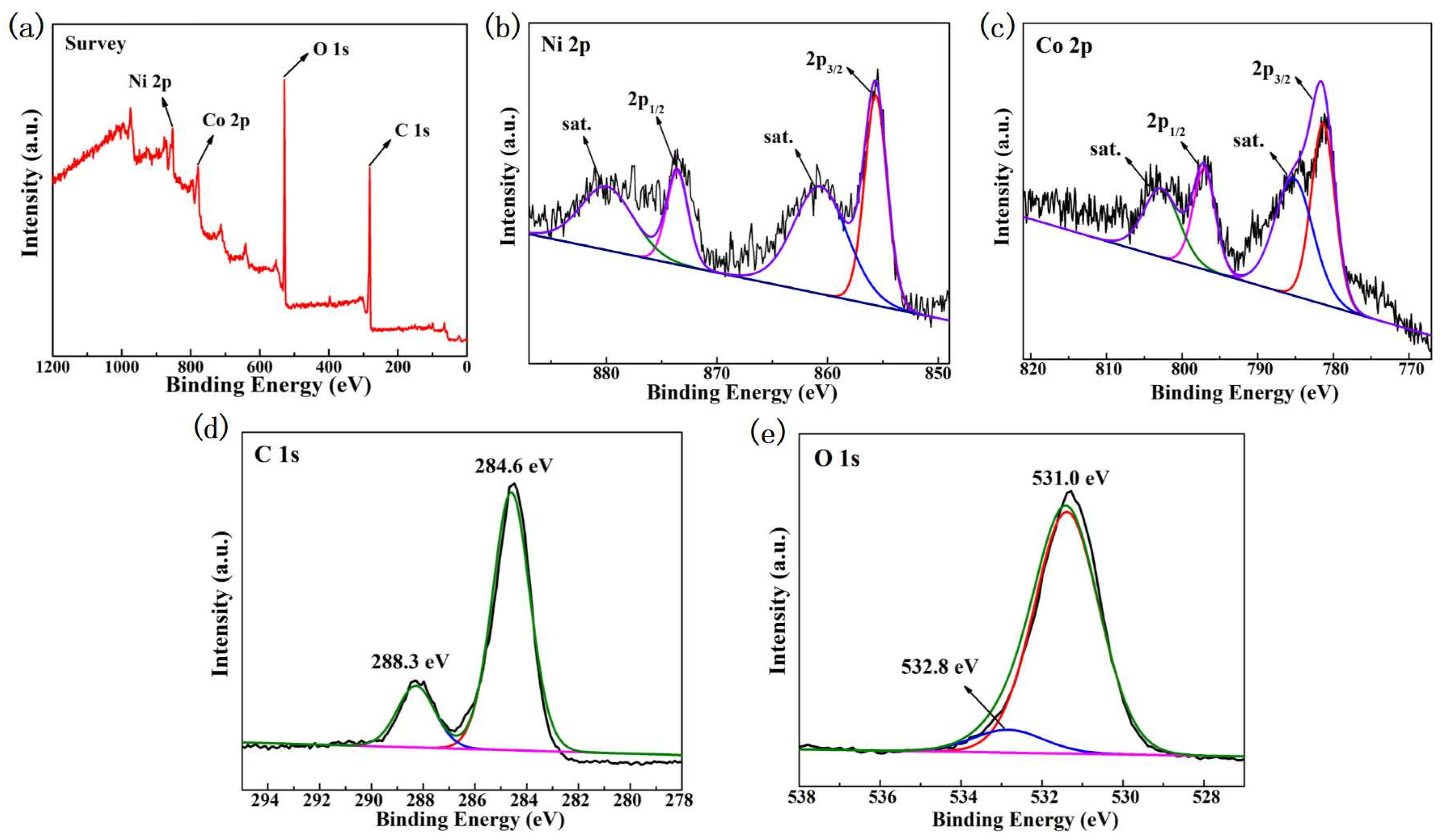
3.1. MOFs Material Characterization

Figure 1 shows the SEM images of NiCo-UMOFs, NiCo-MOFs, Ni-MOFs and Co-MOFs electrocatalytic materials. It can be seen from the figure that NiCo-MOFs prepared using the hydrothermal method are more likely to form large block structures with uneven stacking. Compared with this material, NiCo-UMOFs is a two-dimensional thin structure with a smooth surface stacked layer upon layer, so it may have a larger contactable active area. According to the mapping, the bimetallic materials under the two synthesis methods are successfully loaded with a certain amount of cobalt and nickel.
Comparing NiCo-MOFs, Ni-MOFs and Co-MOFs prepared using the hydrothermal method, these three materials have great differences in micro-morphology. It can be seen from the figure that the mono-metallic Ni material is a tight ultra-thin two-dimensional nanosheet structure, there are obvious holes between the layers, and many active sites are fully exposed. The structure of mono-metal Co material and NiCo-MOFs is like a blocky structure, but the difference is that mono-metal Co material is a smaller blocky structure stacked layer by layer. Through the above analysis, the addition of Co will affect the structure of Ni-MOFs, to some extent. Combined with the measured properties, it is found that the introduction of the Co component affects the morphology of the original nickel-based material.
The X-ray diffraction images of NiCo-UMOFs and NiCo-MOFs are shown in Figure 2. As we can see, the strong diffraction peaks appear in Ni-MOFs at 2θ degrees of about 45º, which is attributed to the nickel peak. The XRD pattern of Co-MOFs exhibited weaker peaks at 2θ degrees of 33.5°. NiCo-UMOFs and NiCo-MOFs have similar diffraction peaks to Ni-MOFs, indicating that the introduction of Co did not affect the structure of Ni-MOF, and NiCo-UMOFs is successfully prepared.
The XPS measurements of NiCo-UMOFs were detected and the results are displayed in Figure 3. The survey spectrum (Figure 3a) demonstrates the presence of Ni, Co, O, and C elements in NiCo-UMOF. In the Ni 2p spectrum (Figure 3b), the characteristic peaks at 855.6 and 873.8 eV are attributed to Ni 2p3/2 and Ni 2p1/2, respectively, with the two satellite peaks at 861.4 and 880.1 eV [28]. In the Co 2p spectrum (Figure 3c), the characteristic peaks located at 781.1 and 797.4 eV correspond to Co 2p3/2 and Co 2p1/2, and the two satellite peaks are centered at 785.6 and 801.5 eV [29]. The above results indicate that Ni and Co ions exist in the form of Ni2+ and Co2+, respectively, in the synthesized NiCo-UMOFs. The C 1s spectrum (Figure 3d) is divided into two peaks at 284.6 and 288.3 eV, which correspond to the bonds of C-C=C and O-C=O, respectively [30]. The O 1s spectrum (Figure 3e) is indexed into two peaks, which are attributed to the metal-oxygen bonds M-O-M (531.0 eV) in the metal oxides and the oxygen in -OH (532.8 eV) [31]. Thus, XPS results verify the formation of the nickel and cobalt phthalic acid phases.

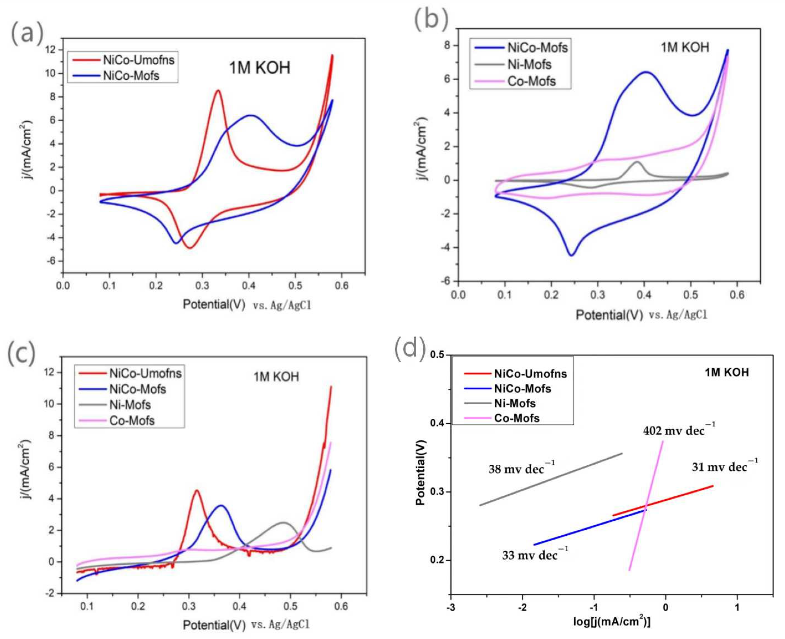
3.2. Electrocatalytic Performance

A cyclic voltammetry test was carried out in 1 M KOH, and the results are shown in Figure 4. As shown in Figure 4a, during forward scanning, an oxidation peak of NiCo-UMOFs material appears in the range of 0.25–0.35 V, which may correspond to the conversion of cobalt trivalent into higher-valence cobalt. Due to the occurrence of the oxygen evolution reaction, the current of NiCo-UMOFs rises sharply after about 0.5 V. In the reverse scan, the reduction peak in the range of 0.2–0.35 V should correspond to the reversal of the transformation in the forward scan. It can be seen from the figure that NiCo-UMOFs material has a higher current passing through the same contact area and the same potential. In addition, by comparing the graphs obtained from the CV test of these two materials at 1 M KOH in the figure, it can be clearly seen that the oxidation peak of NiCo-MOFs becomes wider and has a weaker acromion at about 0.35 V and 0.45 V during forward scanning. It is speculated that the characteristic oxidation peaks may be the conversion of cobalt (II) to cobalt (III) and nickel (II) to nickel (III), respectively. It can also be seen from Figure 4b that the electrocatalytic activity of both Ni-MOFs and Co-MOFs is lower than that of NiCo-MOFs. NiCo-UMOFs and NiCo-MOFs showed good electrocatalytic performance in the potential range of 0.08–0.58 V. Moreover, it can be observed clearly that NiCo-UMOFs material synthesized using the ultrasonic method has better electrocatalytic performance.
In addition, the LSV diagram measured in 1 M KOH solution can be seen in Figure 4c; the initial potential of the NiCo-UMOFs material is about 0.5 V, while, compared with all the other materials, the initial potential of NiCo-MOFs, Ni-MOFs and Co-MOFs is about 0.53, 0.55 and 0.56 V, respectively. According to the Tafel curve in Figure 4d, the Tafel slope of the NiCo-UMOFs material (31 mV/dec) is much smaller than that of NiCo-MOFs (33 mV/dec), Ni-MOFs (38 mV/dec) and Co-MOFs (402 mV/dec). The results show that the electrode material has faster reaction kinetics, which further confirms that the electrocatalytic performance of the material prepared using the ultrasonic method is better.
Based on the above results, it can be concluded that bimetallic organic-skeleton nanomaterials have the optimal electrochemical active area compared to single metals, and the NiCo UMOFs material prepared using the ultrasonic method has a larger electrochemical active area. To some extent, it has also been confirmed that nickel–cobalt bimetallic organic-skeleton nanomaterials have better electrocatalytic activity compared to single metals, and the nickel–cobalt bimetallic organic-skeleton nanomaterials prepared using the ultrasonic method have the best electrocatalytic performance.
The CV curve in Figure 5a shows the UOR under 1 M KOH + 0.7 M urea. Compared with the CV diagram in the background solution (Figure 3), it can be seen that the current density increases sharply after reaching the initial oxidation potential, which indicates that a strong UOR reaction occurs in this system. In addition, it is worth noting that the reduction peak of the electrochemically active substance under the condition of 1 M KOH + 0.7 M urea is much smaller than the corresponding reduction peak in the background solution, which indicates that some high-valence electrochemically active substances have been reduced.
In addition, the catalytic activity of UOR on glassy carbon electrode modified by different materials was further studied using the LSV test. As shown in Figure 5b, compared with the other three materials, the initial potential of the Ni-MOFs is higher and the oxidation current generated under the same potential condition is lower. In addition, the NiCo-MOFs, after doping Co, not only reduces the initial potential of UOR, but also produces significant current at a lower potential, indicating that the UOR electrocatalytic performance of Ni-Co bimetallic materials is better. The NiCo-UMOFs demonstrated the largest UOR current density, with onset potentials of 0.32 V (vs. Ag/AgCl). The Tafel curve based on LSV data measured under 1 M KOH + 0.7 M urea condition can be obtained (Figure 5c). The Tafel slope of the NiCo-UMOFs material (51 mV/dec) is much lower than that of the NiCo-MOFs (97 mV/dec), Ni-MOFs (171 mV/dec) and Co-MOFs (201 mV/dec), which indicates that the electrode material has faster reaction kinetics. It is further confirmed that the material prepared using the ultrasonic method has better performance for UOR electrocatalysis.
On this basis, the stability of NiCo-UMOFs and NiCo-MOFs in 1 M KOH + 0.7 M urea electrolytic solution was further investigated by applying a constant potential of 0.5 V. As shown in Figure 5d, the two materials have obvious current density fluctuations during the I-t test for 24 h, which may be caused by the unstable current density caused by some bubbles on the electrode surface under constant potential conditions. Overall, both NiCo-UMOFs and NiCo-MOFs have good stability in 1 M KOH + 0.7 M urea solution after applying a constant potential of 0.5 V. By contrast, NiCo-UMOFs achieved a higher current density of 13 mA cm−2, and has better catalytic performance toward UOR.

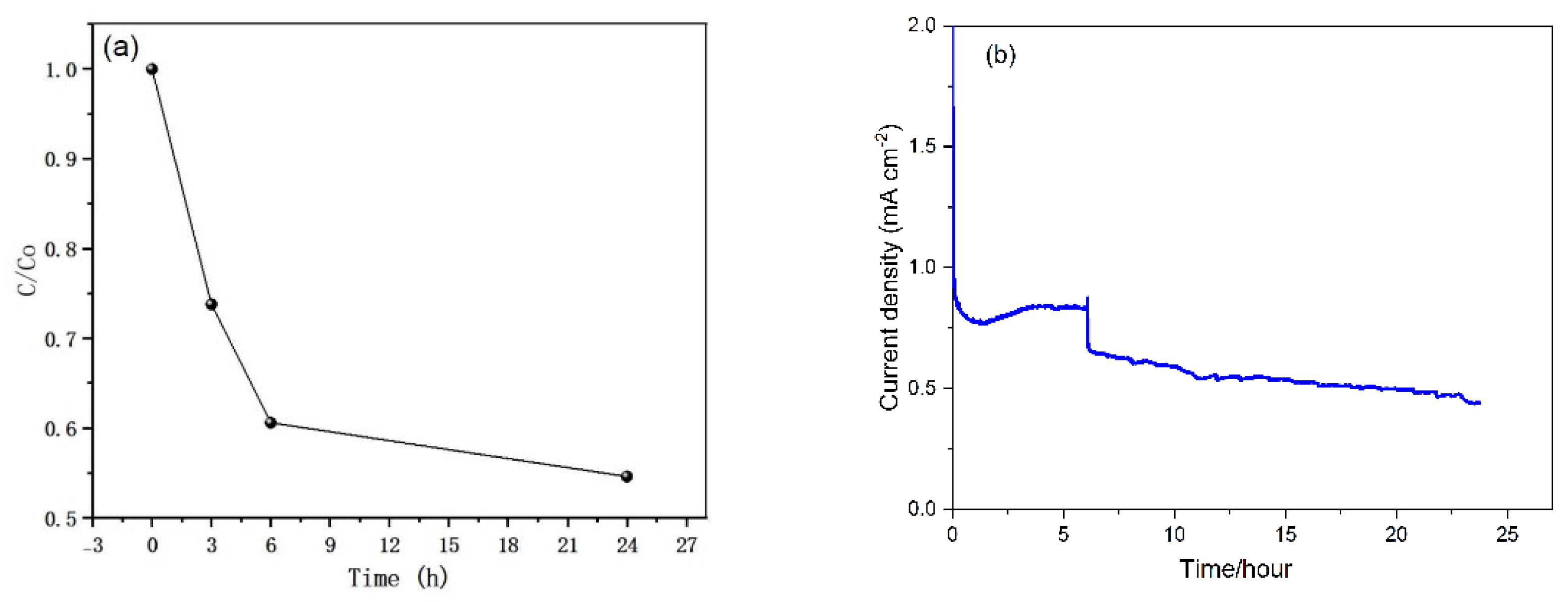
3.3. Study on Urea Degradation

According to the above research on the properties of the four materials for electrocatalytic urea, it can be concluded that the NiCo-UMOFs material prepared using the ultrasonic method has the best electrocatalytic properties. Hence, we use NiCo-UMOFs as anode catalyst for urea degradation. In order to amplify the electrode area, a carbon fiber electrode with an electrode area of 6 cm2 is used as a supporting electrode instead of a glassy carbon electrode. Then NiCo-UMOFs is proportionally coated onto the carbon fiber electrode, using a similar method. A prolonged urea electrolysis test is carried out with the NiCo-UMOFs modified carbon fiber electrode at a constant potential of 0.5 V vs. Ag/AgCl in 70 mL of 1 M KOH solution containing 50 mg/L urea. The effect of catalytic urea degradation is shown in Figure 5. The initial urea concentration (C0) is about 50 mg L−1 in Figure 6a. During urea electrolysis, the urea concentration decreased quickly to about 37.3 mg L−1 in the first 3 h. After 24 h, the urea concentration further reduced to about 27.6 mg L−1, with about 45.4% of urea removal efficiency. In Figure 6b, the current density declined from 1.9 mA cm−2 to 0.4 mA cm−2 in 24 h. This was because the urea concentration reduced relatively fast during this time, as the urea was electro-oxidized, leading to concentration polarization of the anode.

4. Discussion

We compared the performance for electrocatalytic urea oxidation of NiCo-UMOFs with some reported Ni and Co-based catalysts, as summarized in Table 1. It is obvious from the table that NiCo-UMOFs achieved an onset potential of 0.32 V (vs. Ag/AgCl), which is lower than the other catalysts, even some composite catalysts. Moreover, NiCo-UMOFs achieved a higher current density of 13 mA cm2 toward UOR, which is also competitive among these UOR catalysts. From the LSV test in KOH and urea solution, the UOR electrocatalytic performance of Ni-Co bimetallic materials is better than Co-MOFs and Ni-MOFs, indicating that doping Co facilitates the UOR. From SEM images, NiCo-UMOFs presented a two-dimensional thin structure with a smooth surface, so it possessed both the characteristics of the bulk MOFs and a high percentage of exposed-metal active sites on the surface, facilitating more interactions between the active sites and urea and thus enhancing the UOR performance of NiCo-UMOFs. So, the good UOR performance of NiCo-UMOFs could be attributed to the cooperation of Ni and Co, the rich, exposed catalytic sites, and the huge surface area.

5. Conclusions

In this work, NiCo-UMOFs, NiCo-MOFs, Co-MOFs and Ni-MOFs were prepared using the ultrasonic method and hydrothermal method, respectively. The physical surface characteristics of these four catalysts were reflected by SEM and XRD. The Co addition led to a smaller blocky morphology stacked layer by layer. The electrocatalytic properties of various materials were reflected through the determination of CV, LSV and I-t, and the results showed that NiCo-UMOFs prepared using the ultrasonic method had the best performance for electrocatalytic urea reaction and had good stability. This work develops alternative electrocatalysts for UORs.

Author Contributions

Conceptualization, B.Y., H.Y.; methodology, H.Y., W.X., H.C. and G.X.; investigation, L.L. and J.Z.; writing—original draft preparation, B.Y. and H.Y.; writing—review and editing, H.Y., R.H. and L.Z.; supervision, B.Y.; project administration, B.Y.; funding acquisition, B.Y. All authors have read and agreed to the published version of the manuscript.

Funding

This research was funded by the NNSF of China (grant nos. 22202146, 22272115, 22202145, 22202147), Zhejiang Provincial Natural Science Foundation of China (grant no. LGG21B070001), Key Research and Development Plan of Zhejiang Province (2021C03022), and National Innovation Training program for college students (grant no. 202210350038).

Data Availability Statement

Data are contained within the article.

Conflicts of Interest

The authors declare no conflict of interest.

References

  1. Rollinson, A.N.; Jones, J.; Dupont, V.; Twigg, M.V. Urea as a hydrogen carrier: A perspective on its potential for safe, sustainable and long-term energy supply. Energy Environ. Sci. 2011, 4, 1216–1224. [Google Scholar] [CrossRef]
  2. Boggs, B.K.; King, R.L.; Botte, G.G. Urea electrolysis: Direct hydrogen production from urine. Chem. Commun. 2009, 32, 4859–4861. [Google Scholar] [CrossRef] [PubMed]
  3. Lan, R.; Tao, S.; Irvine, J.T.S. A direct urea fuel cell-power from fertiliser and waste. Energy Environ. Sci. 2010, 3, 438–441. [Google Scholar] [CrossRef]
  4. Gao, X.; Wang, Y.; Li, W.; Li, F.; Arandiyan, H.; Sun, H.; Chen, Y. Free-standing Ni-Co alloy nanowire arrays: Efficient and robust catalysts toward urea electro-oxidation. Electrochim. Acta 2018, 283, 1277–1283. [Google Scholar] [CrossRef]
  5. Wang, G.; Ling, Y.; Lu, X.; Wang, H.; Qian, F.; Tong, Y.; Li, Y. Solar driven hydrogen releasing from urea and human urine. Energy Environ. Sci. 2012, 5, 8215–8219. [Google Scholar] [CrossRef]
  6. Xie, L.; Liu, Q.; Luo, Y.; Liu, Z.; Xu, Y.; Asiri, A.M.; Sun, X.; Xie, F. Bimetallic NiCoP nanosheets array for high-performance urea electro-oxidation and less energy-intensive electrolytic hydrogen production. ChemistrySelect 2017, 2, 10285–10289. [Google Scholar] [CrossRef]
  7. Liu, Q.; Xie, L.; Qu, F.; Liu, Z.; Du, G.; Asiri, A.M.; Sun, X. A porous Ni3N nanosheet array as a high-performance non-noble-metal catalyst for urea-assisted electrochemical hydrogen production. Inorg. Chem. Front. 2017, 4, 1120–1124. [Google Scholar] [CrossRef]
  8. Yu, Z.; Lang, C.; Gao, M.; Chen, Y.; Fu, Q.; Duan, Y.; Yu, S. Ni-Mo-O nanorod-derived composite catalysts for efficient alkaline water-to-hydrogen conversion via urea electrolysis. Energy Environ. Sci. 2018, 11, 1890–1897. [Google Scholar] [CrossRef]
  9. Zou, S.; He, Z. Enhancing wastewater reuse by forward osmosis with self-diluted commercial fertilizers as draw solutes. Water Res. 2016, 99, 235–243. [Google Scholar] [CrossRef]
  10. Yu, B.B.; Xu, W.; Jin, Y.X. Short review of self-powered nitrogen removal via abiotic electrochemical catalysis. Processes 2023, 11, 1096. [Google Scholar] [CrossRef]
  11. Rollinson, A.N.; Rickett, G.L.; Lea-Langton, A.; Dupont, V.; Twigg, M.V. Hydrogen from urea-water and ammonia–water solutions. Appl. Catal. B Environ. 2011, 106, 304–315. [Google Scholar] [CrossRef]
  12. Wang, J.; Li, S.; Guo, S.; Ma, C.; Wang, J.; Sun, J. Analysis of heat transfer properties of hollow block wall filled by different materials in solar greenhouse. Eng. Agric. Environ. Food 2017, 10, 31–38. [Google Scholar] [CrossRef]
  13. Wang, X.; Wang, S.; Xue, T.; Li, B.; Dai, X.; Peng, Y. Treating low carbon/nitrogen (C/N) wastewater in simultaneous nitrification-endogenous denitrification and phosphorous removal (SNDPR) systems by strengthening anaerobic intracellular carbon storage. Water Res. 2015, 77, 191–200. [Google Scholar] [CrossRef] [PubMed]
  14. Sha, L.; Yin, J.; Ye, K.; Wang, G.; Zhu, K.; Cheng, K.; Yan, J.; Wang, G.; Cao, D. The construction of self-supported thorny leaf-like nickel-cobalt bimetal phosphides as efficient bifunctional electrocatalysts for urea electrolysis. J. Mater. Chem. A 2019, 7, 9078–9085. [Google Scholar] [CrossRef]
  15. Wang, D.; Vijapur, S.H.; Wang, Y.; Botte, G.G. NiCo2O4 nanosheets grown on current collectors as binder-free electrodes for hydrogen production via urea electrolysis. Int. J. Hydrogen Energy 2017, 42, 3987–3993. [Google Scholar] [CrossRef]
  16. Wang, X.; Wang, J.; Sun, X.; Wei, S.; Cui, L.; Yang, W.; Liu, J. Hierarchical coral-like NiMoS nanohybrids as highly efficient bifunctional electrocatalysts for overall urea electrolysis. Nano Res. 2018, 11, 988–996. [Google Scholar] [CrossRef]
  17. Zhu, D.; Guo, C.; Liu, J.; Wang, L.; Du, Y.; Qiao, S. Two-dimensional metal-organic frameworks with high oxidation states for efficient electrocatalytic urea oxidation. Chem. Commun. 2017, 53, 10906–10909. [Google Scholar] [CrossRef]
  18. Singh, R.K.; Rajavelu, K.; Montag, M.; Schechter, A. Advances in catalytic electrooxidation of urea: A review. Energy Technol. 2021, 9, 2100017. [Google Scholar] [CrossRef]
  19. Ananthamj, S.; Noda, S. Amorphous catalysts and electrochemical water splitting: An untold story of harmony. Small 2020, 16, 1905779. [Google Scholar] [CrossRef]
  20. Xu, W.; Wu, Z.C.; Tao, S.W. Urea-based fuel cells and electrocatalysts for urea oxidation. Energy Technol. 2016, 4, 1329–1337. [Google Scholar] [CrossRef]
  21. Xu, W.; Zhang, H.M.; Li, G.; Wu, Z.C. Nickel-cobalt bimetallic anode catalysts for direct urea fuel cell. Sci. Rep. 2014, 4, 5863. [Google Scholar] [CrossRef] [PubMed]
  22. Xu, W.; Yan, Z.Z.; Liu, C.H.; Yang, X.; Yu, H.; Chang, H.C.; Zang, J.R.; Xu, G.Y.; Du, L.M.; Yu, B.B. Electrocatalytic behavior of amino compound oxidation on NiCo catalyst and energy conversion. Energy Adv. 2023, 2, 1752. [Google Scholar] [CrossRef]
  23. Zhou, H.-C.; Kitagawa, S. Metal-organic frameworks (MOFs). Chem. Soc. Rev. 2014, 43, 5415–5418. [Google Scholar] [CrossRef] [PubMed]
  24. Xu, Y.; Chai, X.; Ren, T.; Yu, S.; Yu, H.; Wang, Z.; Li, X.; Wang, L.; Wang, H. Ir-Doped Ni-based metal-organic framework ultrathin nanosheets on Ni foam for enhanced urea electro-oxidation. Chem. Commun. 2020, 56, 2151–2154. [Google Scholar] [CrossRef] [PubMed]
  25. Wang, L.; Ren, L.; Wang, X.; Feng, X.; Zhou, J.; Wang, B. Multivariate MOF-templated pomegranate-like Ni/C as efficient bifunctional electrocatalyst for hydrogen evolution and urea oxidation. ACS Appl. Mater. Interfaces 2018, 10, 4750–4756. [Google Scholar] [CrossRef]
  26. Cheng, Y.; Xiao, X.; Guo, X.; Yao, H.; Pang, H. Synthesis of “Quasi-Ce-MOF” electrocatalysts for enhanced urea oxidation reaction performance. ACS Sustain. Chem. Eng. 2020, 8, 8675–8680. [Google Scholar] [CrossRef]
  27. Hu, S.; Wang, S.; Feng, C.; Wu, H.; Zhang, J.; Mei, H. Novel MOF-derived nickel nitride as high-performance bifunctional electrocatalysts for hydrogen evolution and urea oxidation. ACS Sustain. Chem. Eng. 2022, 8, 7414–7422. [Google Scholar] [CrossRef]
  28. Veeramani, V.; Madhu, R.; Chen, S.M.; Sivakumar, M.; Hung, C.T.; Miyamoto, N.; Liu, S.B. NiCo2O4-decorated porous carbon nanosheets for high-performance supercapacitors. Electrochim. Acta 2017, 247, 288–295. [Google Scholar] [CrossRef]
  29. Wang, X.Y.; Liu, B.B.; Li, J.; Zhai, Y.Y.; Liu, H.Q.; Li, L.; Wen, H.R. Conductive 2D metal-organic framework (Co, NiCo, Ni) nanosheets for enhanced non-enzymatic detection of urea. Electroanalysis 2021, 33, 1484–1490. [Google Scholar] [CrossRef]
  30. Zhang, T.; Du, J.; Xi, P.; Xu, C. Hybrids of cobalt/iron phosphides derived from bimetal-organic frameworks as highly efficient electrocatalysts for oxygen evolution Reaction. ACS Appl. Mater. Interfaces 2017, 9, 362–370. [Google Scholar] [CrossRef]
  31. Wang, Q.; Wang, Q.; Xu, B.; Gao, F.; Gao, F.; Zhao, C. Flowershaped multiwalled carbon nanotubes@nickel-trimesic acid MOF composite as a high-performance cathode material for energy storage. Electrochim. Acta 2018, 281, 69–77. [Google Scholar] [CrossRef]
  32. Yue, X.; Yao, S.; Li, Y.; Zhu, W.; Zhang, W.; Wang, R.; Wang, J.; Huang, L.; Zhao, D.; Wang, J. Surface engineering of hierarchical Ni(OH)2 nanosheet@nanowire configuration toward superior urea electrolysis. Electrochim. Acta 2018, 268, 211–217. [Google Scholar] [CrossRef]
  33. Ji, X.Y.; Zhang, Y.X.; Ma, Z.; Qiu, Y.F. Oxygen vacancy-rich Ni/NiO@NC nanosheets with schottky heterointerface for efficient urea oxidation reaction. ChemSusChem 2021, 13, 5004–5014. [Google Scholar] [CrossRef] [PubMed]
  34. Alex, C.; Shukla, G.; John, N.S. Introduction of surface defects in NiO with effective removal of adsorbed catalyst poisons for improved electrochemical urea oxidation. Electrochim. Acta 2021, 385, 138425. [Google Scholar] [CrossRef]
  35. Gao, S.Q.; Fan, J.C.; Xiao, G.C.; Cui, K.X.; Wang, Z.H.; Huang, T.; Tan, Z.C.; Niu, C.Q.; Luo, W.B.; Chao, Z.S. Synthesis of FeCo2O4@Co3O4 nanocomposites and their electrochemical catalytical performaces for energy-saving H2 prodcution. Int. J. Hydrogen Energy 2023, 48, 17147–17159. [Google Scholar] [CrossRef]
  36. Mahmoud, A.; Hefnawy, S.S.; Medany, R.M.; El-Sherif, S.A. Green synthesis of NiO/Fe3O4@chitosan composite catalyst based on graphite for urea electro-oxidation. Mater. Chem. Phys. 2022, 290, 126603. [Google Scholar] [CrossRef]
  37. Mohammad, A.A.; Hussain, A.; Olabi, A.G. Enhancing the performance of direct urea fuel cells using Co dendrites enas etaha sayed. Appl. Surf. Sci. 2021, 555, 149698. [Google Scholar] [CrossRef]
Figure 1. Scanning electron microscopy and energy spectrum of (a,b) NiCo-UMOFs and (c,d) NiCo-MOFs; SEM images of (e,f) Ni-MOFs and (g,h) Co-MOFs at different scanning sizes.
Processes 11 03035 g001
Figure 2. X-ray diffraction of Ni-MOFs, Co-MOFs, NiCo-UMOFs and NiCo-MOFs.
Processes 11 03035 g002
Figure 3. XPS spectra of NiCo-UMOFs.: (a) Survey, (b) Ni 2p, (c) Co 2p, (d) C 1s, and (e) O 1s.
Processes 11 03035 g003
Figure 4. Cyclic voltammetry plots of (a) NiCo-UMOFs and NiCo-MOFs, (b) NiCo-MOFs, Ni-MOFs, and Co-MOFs coated on a glassy carbon electrode in a 1 M KOH solution; (c) Linear scanning voltammograms of four different materials coated on glassy carbon electrodes in 1 M KOH solution, with a scanning speed of 5 mV/s; (d) Tafel curves for four different materials.
Processes 11 03035 g004
Figure 5. (a,b) CV and LSV plots of all materials coated on a glassy carbon electrode in a 1 M KOH + 0.7 M urea solution, with scanning rates of 10 mV/s and 5 mV/s, respectively; (c) Tafel curves of all materials coated on a glassy carbon electrode in 1 M KOH + 0.7 M urea solution; (d) I-t curves of four different materials at a constant potential of 0.5 V.
Processes 11 03035 g005
Figure 6. (a) Diagram of the ratio of instantaneous urea concentration (C) to initial urea concentration (C0) within 24 h; (b) Current-density curve of prolonged urea electrolysis.
Processes 11 03035 g006
Table 1. Comparison of different catalysts for UOR performances.
CatalystsOnset Potential
(V vs. Ag/AgCl)
Current Density (mA/cm−2)References
Ni(OH)2NS@NW0.7326[32]
Ni/NiO nanosheets0.3810[33]
NiO0.3320[34]
FeCo2O4@Co3O40.4210[35]
NiO/Fe3O4@chitosan0.4535.4[36]
Co dendrites0.3521[37]
NiCo-UMOFs0.3213This work
Disclaimer/Publisher’s Note: The statements, opinions and data contained in all publications are solely those of the individual author(s) and contributor(s) and not of MDPI and/or the editor(s). MDPI and/or the editor(s) disclaim responsibility for any injury to people or property resulting from any ideas, methods, instructions or products referred to in the content.

