Article

Studies on a Novel Jet Mixer in the Extraction Process

by
Wojciech Piotrowski
1,
Robert Kubica
1,* and
Maksymilian Gądek
2
1
Department of Chemical Engineering and Process Design, Silesian University of Technology, M. Strzody 7, 44-100 Gliwice, Poland
2
Losentech, Chabrowa 1, 44-210 Rybnik, Poland
*
Author to whom correspondence should be addressed.
Processes 2023, 11(10), 2904; https://doi.org/10.3390/pr11102904
Submission received: 9 August 2023 / Revised: 22 September 2023 / Accepted: 30 September 2023 / Published: 2 October 2023

Abstract

:
This paper presents the original results of research on an inline jet mixer being an alternative to other, conventional mixing apparatuses used for extraction processes. In particular, researched novel geometry of a jet mixer was subjected to testing of either hydraulic performance or a liquid–liquid extraction process. Inline jet mixers are well suited for mixing gases and liquids and can be used in such processes as extraction, heat exchange, and reaction. In such an apparatus, mixing of liquids takes place by high-velocity injection of one stream into another through a series of small holes placed peripherally to a concentrically mounted inner tube. The literature lacks the data to allow for the design of these types of mixers. Extraction experiments were performed for the ethyl acetate–ethanol–water system. The research results presented in this paper enable the calculation of mixing power and the selection of optimal mixer operating parameters. Equations describing the flow resistance for both streams were developed. The mixing power was calculated and compared with other types of contactors. The data on overall volumetric mass transfer coefficients obtained by this study showed that the considered extractor is competitive with other conventional contactors at almost identical or even lower energy consumption.

Graphical Abstract

1. Introduction

The mixing process plays a very important role in the chemical industry, and in related industries, as well as in everyday life. It is meant to obtain homogeneity in a single- or multiphase system in terms of composition, density, temperature, and other physicochemical properties [1]. Mixing is an operation also used to intensify such processes as heat and mass exchange, and thus contributes also to the acceleration of chemical reactions [2]. In the case of multiphase systems in processes such as extraction, mixing allows increase in the surface of mass transfer by emulsifying the mixture [3].
Apparatuses used in a process of mixing liquids can be divided into three groups: mechanical mixers, static mixers, and jet mixers [4]. In the case of a mechanical mixer, the operating element is a mechanically driven agitator, while in a static mixer, mixing is caused by currents and vortices introduced to the flowing streams by means of geometry, e.g., obstacles or various types of mixing stationary internals of the apparatus [1]. In jet mixers, a high-velocity stream is injected into another slowly moving or stationary fluid. The difference in velocity creates a mixing layer at the boundary interface of the streams. This agitation interface grows in the flow direction of the stream entraining and mixing the bulk fluid into the stream. The use of turbulent jets to mix fluids is very common in the chemical industry. This process can be carried out in a tank (tank jet mixers) or in pipe inline assemblies (tubular jet mixers) [4].
The use of in-line jet mixers in continuous processes is a competitive alternative to conventional mixing because comparable, or sometimes even better, performance can be achieved at a lower cost. Typically, these mixers have lower energy consumption and fewer maintenance requirements as they have no moving parts. They can also provide homogenization of the feed streams with minimal residence time. Their main advantages over mechanical mixers are [1,4,5]:
  • small overall dimensions;
  • low production costs;
  • no additional power required apart from the pumping power;
  • no moving parts;
  • short residence times;
  • good mixing at low shear rates—no damage to sensitive materials;
  • self-cleaning.
Inline jet mixers are used in various unit processes. The primary role of inline jet mixers is to efficiently mix different substances. They can be used for mixing components in chemical processes, the food industry, pharmaceuticals, and other fields where uniform distribution of components is crucial. This mixer is well suited for mixing gases and liquids, which have low viscosity. Inline jet mixers can be utilized to mix reagents in chemical reaction processes. They guarantee uniform distribution of reagents, which can expedite the reaction and enhance efficiency. In extraction processes, inline jet mixers can be used to contact two liquid phases or a liquid and a gas phase to extract specific substances. In heat exchange processes, particularly in situations requiring efficient heat distribution, inline jet mixers find valuable application. They aid in temperature control and accelerate the heat exchange processes.
Two common types of tubular jet mixers are a coaxial jet mixer [1,4,6] and a side-entry jet mixer [1,4,7]. In a coaxial jet mixer, the injected stream is introduced through a small diameter pipe running concentrically within the large diameter pipe. In a side-entry jet mixer, the stream is injected radially into the main tubular stream. When compared to a coaxial jet mixer, that type of mixer is more suitable for handling streams of significantly different flowrates. It is also easier to manufacture and maintain.
The behavior of a side-stream injected into a cross-flow has been extensively researched, both theoretically and experimentally [7,8,9,10,11,12,13,14]. However, those data are not very useful for practical design purposes.
In order to intensify mixing and mass transfer by extraction processes, a jet mixer has been proposed in which the injection of the fluid will not take place through a single outlet, but through a number of small holes placed peripherally on the inner tube. The main purpose of the herein presented research is to analyze the hydraulics and mass transfer of such a jet mixer. The exact design of the tested mixer is shown in Figure 1. In such an apparatus, mixing takes place by high-velocity injection of one stream into another through a series of small holes placed over the perimeter of the concentrically mounted inner tube.
The literature lacks the data to allow for the design of these types of mixers. Forney et al., in their work, studied tee-mixers and multi-jet mixers with one row of holes and with between one and four jets [7,8,9]. Therefore, an attempt was made at first to determine the correlation equations describing the flow resistances of both mixed streams. For that purpose, pressure drops of streams introduced to the mixer were measured. These measurements allowed for the development of the equations describing the dependence of a mixing power on the geometrical parameters of the apparatus, as well as the physicochemical properties of the media used. The influence of hydraulic parameters of mixed streams, i.e., linear velocity, on the extraction efficiency in the studied mixer was also examined with the use of model assembly on a laboratory scale.

2. Hydraulics

2.1. Methodology

Hydraulic tests were carried out for a water system at a temperature close to ambient (18–22 °C). Water in a closed circuit was pumped through a jet mixer and the pressure drop of mixed streams was measured. The measurements were performed at a variable volumetric flow rate of mixed water streams. To prevent the formation of air bubbles disturbing the liquid flow and measurements, the system was siphoned and equipped with vent valves.
The experimental apparatus, shown in Figure 1, consists of the following parts:
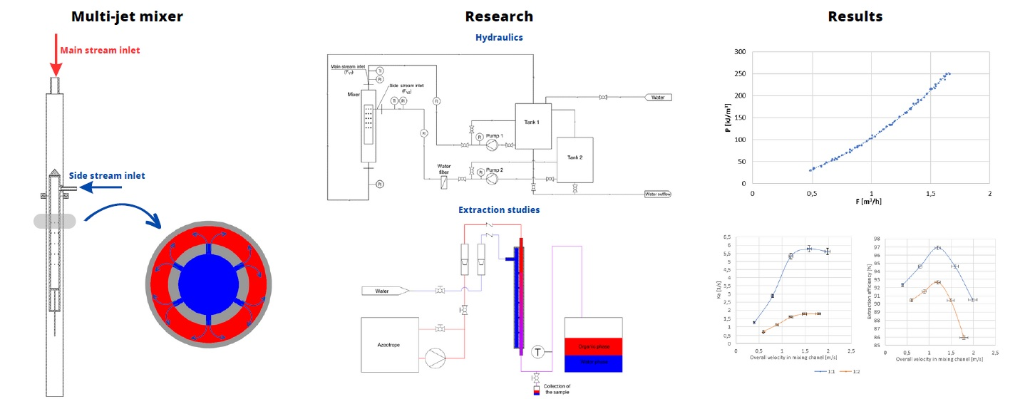
  • an outer pipe (2) into which the main stream is introduced from above (1);
  • a perforated inner pipe (3) with side stream inlet (4);
  • holes in the inner pipe (5), through which the side stream is injected into the main stream;
  • a piston (6) that makes it possible to change the number of active rows of holes through which the liquid is injected. This allowed investigation of the effect of the number of injection holes on the pressure drops at both branches of the apparatus;
  • an outlet (7).
The tests included measurements of the volumetric flow rate of the inlet streams, their temperature, and static pressure in selected measurement sections. A detailed diagram of the testing rig, with the metering equipment and instrumentation, is presented in Figure 2.
Electronic pressure sensors (A10 WIKA, Poland; NPXD Peltron, Wiązowna Kościelna, Poland) were used to measure the static head of the fluids. The volumetric flow rate of the water streams was measured using ultrasonic flow meters (Qalcosonic W1, Termabud, Poland). The temperature of the flowing fluids was measured using resistance temperature sensors (TR40, WIKA, Poland). The sensors were connected to a data logger (CMC-99, MultiCon, Poland). The range of flow rate variability was as follows:
-
main stream (Fv1) 1–2.8 m3/h;
-
side stream (Fv2) 0.5–2 m3/h;
and the range of Reynolds numbers was as follows:
-
main stream (Re1) 7000–21,000;
-
in holes (Reh) 2500–22,000.
The range of Reynolds numbers was chosen so that the flow was turbulent and mixing resulted from turbulent diffusion (Re > 2000) [8].

2.2. Analysis and Discussion of the Results

The pressure drop is the most important design criterion for a jet mixer. It permits quantification of the dissipated power in the mixer. Dimensional analysis was used to describe the pressure drop of the main stream p 1 . The flow resistance of the main stream is directly related to the velocity of the fluid. Since, in the analyzed case, there are two mixing streams, it was assumed that the velocity of main stream Fv1 in the annular area ( v e ) and the velocity of the stream Fv2 in the holes ( v h ) would have the most significant influence on the pressure drop of the main stream. Other parameters affecting the pressure drop are the physical properties of the mixed streams, such as viscosity coefficients ( η 1 , η 2 ), densities (ρ1, ρ2), and surface tension ( σ ) .
The geometry of the mixer is also important for determining the pressure drops. It was decided to use the equivalent diameter of the annular area de and the hole diameter dh as variables. Due to stream flow inconsistency with the direction of gravity forces, it was decided to take into account the gravitational acceleration g in the pressure drop equation.
The general equation took the following form:
p 1 = f ( η 1 , ρ 1 , v e , d e , η 2 , ρ 2 , v h ,   d h , g ,   σ )          
After carrying out a dimensional analysis, the following equations were obtained:
E u 1 = p 1 ρ 1 · v e 2 = A ρ 1 · d e · v e η 1 B ρ 2 · d h · v h η 2 C v e 2 g · d e D   v h v e E ρ 1 ρ 2 F ρ 1 · d e · v e 2 σ G d e d h H
The equivalent diameter of the annular area de was calculated from the formula:
d e = 4 S P = d 1 2 d 2 2 d 1 + d 2
As the impact of change diameters was not analyzed, the last module was eliminated from the equation as part of the constant A. To express the momentum ratio of the mixed streams, the module   v e v h was combined with the module ρ 1 ρ 2 , and the number of rows of holes added to the formula:
n   v h v e E ρ 1 ρ 2 F = n ρ 2 v h 2 ρ 1 v e 2 I
The final formula for the pressure drop of the main stream was reduced to the following form:
E u 1 = p 1 ρ 1 · v e 2 = A ( ρ 1 · d e · v e η 1 ) B ( ρ 2 · d h · v h η 2 ) C v e 2 g · d e D n ρ 2 v h 2 ρ 1 v e 2 E ρ 1 · d e · v e 2 σ F = = A ( R e 1 ) B ( R e h ) C F r D M E W e F
The Euler (Eu) number is defined as the ratio of pressure forces to inertial forces in the flow. It is a value used in fluid flow calculations to characterize energy losses in the flow. It represents the relationship between a local pressure drop and the kinetic energy per volume of the flow. The Euler number (Eu) is widely used in fluid mechanics and is an important dimensionless number for analyzing flow behavior and energy losses in fluid systems. When the Euler number is greater than 1, it indicates a significant pressure drop in the flow, while a value close to 0 corresponds to a perfect frictionless flow. Apart from the Euler number, the following dimensional numbers are present in the correlation equation (Equation (5)):
Reynolds number for the main stream (Re1) and for the side stream in the holes (Reh). It is defined as the ratio between the inertia force and the viscous force in a fluid flow.
Froude number (Fr), defined as the ratio of inertial forces to gravitational forces acting on a fluid.
Momentum ratio (M) quantifies the relative importance of the momentum carried by the jet compared to the momentum of the surrounding fluid. It indicates how much the jet will influence the mixing process. In a jet mixer, a high momentum ratio implies a dominant primary stream that can induce strong mixing effects and disperse the secondary fluid efficiently. Conversely, a low momentum ratio suggests that the secondary fluid has a significant influence on the mixing process, potentially resulting in less efficient mixing or less dispersion of the primary stream.
The Weber number (We) is a dimensionless parameter that relates the inertial forces to the surface tension forces in a fluid flow. In the context of a jet mixer, the Weber number can be used to assess the behavior and characteristics of the streams involved. For a jet mixer, the Weber number of the streams can provide insights into the breakup and atomization behavior of the primary jet and the mixing process.
The pressure drop of the side stream p 2 can be described as the sum of the pressure drops in the inlet pipe ( p i n ) due to sudden expansion and flow direction change ( p s ) in the central pipe ( p p ) and in the holes p h :
p 2 = p i n + p s + p p + p h
The flow in the holes depends on the pressure difference between the main stream and the side stream (p2p1). Due to the fact that p2 is much greater than p1 and ∆p1 is negligible in relation to p2 (p2p1p2 − (p1∆p1)), uniform outflow through the holes was assumed.
Local pressure drops were expressed by Equations (7)–(9). The Darcy–Weisbach equation was used to calculate the pressure drop in straight pipes, and the Blasius equation ( λ = 0.3164 R e 0.25 ) was used to calculate the flow coefficient λ for Re > 3000 (Rein2 = <12,700;58,000>, Rep = <6350;29,000>) [15]. The local resistance coefficient ξ caused by the sudden expansion and change of direction of the stream is described by a linear function, where the variable is R e i n 2 and the parameters of functions A and B were determined on the basis of experimental data [16]. For turbulent flow, a linear function often provides a satisfactory fit to experimental data. In the case of pressure drop in the holes, the orifice equation was used, where ξ was expressed using the function ξ = C + D R e h E . Parameters C, D, and E were determined based on experimental data [17].
p i n = ρ 2 v i n 2 2 2 0.3164 R e i n 2 0,25 l 1 d i n 2 s t r a i g h t   p i p e
p s = ρ 2 v i n 2 2 2 A + B R e i n 2 s u d d e n   e x p a n s i o n   a n d   f l o w   d i r e c t i o n   c h a n g e  
p p = ρ 2 v p 2 2 0.3164 R e p 0.25 l 2 ( d 2 2 s ) s t r a i g h t   p i p e
p h = ρ 2 v h 2 2 C + D R e h E o r i f i c e   e q u a t i o n
The direct aim of the research was to determine the values of the constants and the exponents of the presented criteria equations (Equations (5), (8) and (10)). They will allow calculation of the pressure drop for other cases similar to the tested one, in compliance with the theory of similarity. The constants and the exponents of the equation were determined using the least squares method. The results of the data adjustment for the tested variants are summarized in Table 1 and in Figure 3.
Figure 4 shows the value of the side stream pressure drop (∆p2) and its components (∆ph, ∆pin, ∆ps, ∆pp) as a function of side stream flow Fv2 for five and two rows of holes. Analyzing the data presented in Figure 4, it can be concluded that ∆pin and ∆pp have a negligible impact on the side stream pressure drop. In the case of five rows of holes, ∆ps had the greatest impact on the pressure drop of this stream, and in the case of two rows, ∆ph had a major impact. Due to the fact that ∆pin and ∆pp <<∆ph and ∆ps, the equation for the side stream pressure drop (∆p2) can be simplified to:
p 2 = p s + p h
The parameter that will allow comparison of the tested mixer with other assemblies is the energy input for mixing a unit volume of 1 m3. The energy input to the mixing process is a result of pressure loss through the mixer. In the studied case, this value was determined as follows:
E = p 1 F V 1 + p 2 F V 2 ( F V 1 + F V 2 )
The energy input as a function of the overall velocity for different F V 1 values is shown in Figure 5. Overall velocity is defined as exit velocity from the annular section.
Due to the fact that ∆p2 >> ∆p1, ∆p2 has a major impact on the power input. In the tested flow range, the unit energy input for the assembly with five rows of holes ranged from 8 to 90 kJ/m3, and for the system with two rows varied from 10 to 155 kJ/m3. Dehkordi, in his paper [18], compared different types of mixers for different systems, in terms of their mixing power and mass transfer coefficients. Table 2 shows unit mixing power for the other types of mixers. Having compared this parameter, it can be concluded that the proposed mixer is a competitive alternative to the other mixers.
Based on the obtained power characteristics, the tested mixer can be classified as a high-pressure-drop mixer [1]. Mixers of this type are used in applications where pressure reduction is desirable, such as in gas regulation systems, chemical processes, or cooling systems [1,2]. High-pressure drop mixers are designed with features that induce turbulence and increase the mixing efficiency, which, in turn, leads to a greater pressure drop. In comparison to low-pressure drop mixers, high-pressure drop mixers generally offer better mixing performance [1,2]. However, it is important to note that such mixers can incur higher operational costs, in terms of the energy required to maintain high pressure [1]. Additionally, high-pressure drop mixers may not be the optimal choice for experiments where controlled variability in mixing parameters is crucial, or for applications that demand extra caution due to delicate or sensitive components [19,20].
Table 2. Required power input for various types of mixers [18].
Mixer TypePower Input
(kJ/m3 of liquid)
Agitated extraction column [21]0.5–190
Mixer–settler [21]150–250
IS contactor [18]35–1500
Centrifugal extractor [21]850–2600
Screen-type static mixers [22]36–360
Tested mixer (present work)8–155

3. Extraction Studies

3.1. Methodology

The effectiveness of the extraction process carried out by means of the proposed apparatus was studied experimentally. Testing was carried out with the use of a simplified model of the apparatus, which made it possible to reproduce the actual process conditions.
A model of a part of a jet mixer was developed based on the simplifying assumptions. As the system is symmetrical, it was possible to model only a selected part of it. A closed channel with an area equal to one sixth of the cross-sectional area of the mixer was made. There were five holes introduced longitudinally inside the channel, as to represent five rows of holes of the original assembly. A schematic diagram of the device is presented in Figure 6. The momentum of the mixed streams, and their respective ratio, has a key impact on the extraction, by developing the interphase surface [9,23]. The interphase surface can also be to some extent developed by differential adhesion of the phases on the wall. However, these phenomena can be found negligible in magnitude when compared to the effects of mixing produced by intersecting streams, having very high momentums. With this, we found that a simplified model apparatus (Figure 6) is represents well the model of the whole apparatus. The only differences are the side walls, which may influence the pressure drop to some extent, but surely do not affect the development of the interphase surface and mass transfer, which was studied with a simplified model apparatus.
Rotameters were used to measure the volumetric flow rates of mixed streams. The temperature at the outlet of the mixer was measured to determine the equilibrium state of the mixture. The diagram of the installation for testing the extraction is shown in Figure 6.
For the extraction studies, a mixture of ethyl acetate (99.8%, Sigma-Aldrich, Poznań, Poland), ethanol (99.8% Sigma-Aldrich, Poznań, Poland) and water with the composition of a triple azeotrope (83% ethyl acetate EA, 9% ethanol ET, 8% water W) [24] was prepared. The mixture was extracted with water. Extraction of ethanol from the azeotropic mixture with water is used for production of ethyl acetate [25]. The volume ratios of azeotrope to water used in experiments were 1:1 and 1:2. Figure 7 shows the LL equilibrium diagram for the studied system with marked points for equilibrium composition of the water phase (for 1:1—EA 11%, ET 6.6%, W 82.4%; for 1:2—EA 9.4%, ET 3.7%, W 86.8%) and the organic phase (for 1:1—EA 95.5%, ET 0.6%, W 3.9%; for 1:2 EA 96.5%, ET 0.04%, W 3.46%) after extraction for the tested azeotrope: water volume ratios. The diagram was generated in Chemcad 8 software using the UNIQUAC thermodynamic model, for the temperature of 19 °C and the atmospheric pressure. Direction of extraction in the tested system is from azeotrope mixture to the water phase. Water, by extracting ethanol from the azeotrope, reduces the solubility of water in the organic phase. This causes the water from the organic phase to pass into the water phase as well. A small amount of EA due to its solubility in water was also transferred into the water phase.
In each experimental run, the flow of the azeotrope and water was controlled at the desired value using throttling valves. All tests were carried out in the range of flow rates of 100–600 l/h. After establishing the set operating conditions, a sample of the mixed streams was taken. The sampled mixture was left to settle in the phase separator. After separation of the immiscible liquid phases, a sample of the upper, organic phase was taken to analyze its chemical composition. The content of EA and ET in the sample was determined by gas chromatography, while the Karl–Fischer method was used to determine water. After phase separation, the entire mixture and the organic phase were weighed.

3.2. Methodology for Determining the Composition of the Organic Phase

Gas chromatography
The quantitative analysis of the samples for ethanol and ethyl acetate content was performed using the gas chromatography method with a flame ionization detector (GC-FID) and a Clarus 500 gas chromatograph from PerkinElmer. Capillary columns of the following type were used: SPB5TM (30 m × 0.25 mm × 0.25 μm) with a temperature program: 40 °C |5 min| → 45 °C/1 min → 240 °C |2 min|.
The analysis of the results obtained from gas chromatography was performed using the method of internal calibration, with n-decane as the internal standard. The content of ethyl alcohol and ethyl acetate was determined based on a prepared standard curve. It was prepared by measuring four different concentrations of ethanol and ethyl acetate in n-decane. A linear regression equation was obtained with the formula y = 0.3766x − 0.0271 and with a correlation coefficient of R2 = 0.9999 for ethanol, and y = 0.3820x + 0.0356 with a correlation coefficient of R2 = 0.9996. With the use of the calibration curve, the content of ethanol and ethyl acetate in the tested sample was calculated.
Karl–Fischer method of water analysis
In addition, the water content in the samples was determined utilizing the Metrohm volumetric Karl–Fischer water analyzer. The test sample dissolved in methanol was titrated with a titrant that consisted of alcohol, alkali, iodine, and sulfur dioxide. A platinum electrode was immersed in the vessel to measure the voltage changes of the solution. During sample titration, 1 mole of iodine reacted with 1 mole of water. The voltage dropped during the addition of the titrant. In the course of the reaction, the voltage increased with the loss of iodine in the mixture. After establishing the equilibrium (titration end point), the water content of the test sample was calculated. To calibrate the apparatus, prior to the performed analyses, the titrant titer was determined using an analytical weighed quantity with a water content of 1% by weight. The titer allows determination of the iodine concentration in the titrant. For this purpose, three tests were performed, obtaining a titer of 4.9695 mg/mL, and the relative error of the obtained titer was 0.15%.

3.3. Analysis and Discussion of the Results

The conditions of the process and the results of measurements are summarized in Table 3. The concentration of EA and ET in the organic phase, after extraction of crude solutions of known composition, measured for different, linear velocities in the mixing channel is shown in Figure 8. Inlet stream flow rate ratios have been selected so that the mixer works in optimal conditions according to Forney [8].
The mass transfer coefficient is a characteristic parameter used to evaluate the performance of extractors. The equation for the mass transfer rate for ethanol from the organic phase to water can be written as [18]:
n = K a V m C l n
C l n = C E T , i n C E T , i n * ( C E T , o u t C E T , o u t * ) ln C E T , i n C E T , i n * C E T , o u t C E T , o u t *
As the value of the interfacial surface in the extraction was not investigated experimentally, the total volumetric mass transfer coefficient Ka was determined:
K a = n V m C l n
where:
  • K—mass transfer coefficient, m s
  • a—interfacial mass transfer area between the phases per unit volume of the contactor, m 2 m 3
  • n—extraction rate of ethanol, k m o l s
  • Vm—mixing channel volume, m 3
  • CET,in—inlet ethanol concentration in the dispersed phase, k m o l m 3
  • CET,out—measured ethanol concentration in the dispersed phase after extraction, k m o l m 3
  • CET,in*—equilibrium concentration of ethanol in the dispersed phase, corresponding to the actual inlet concentration of the ethanol in the other phase, k m o l m 3
  • CET,out*—equilibrium concentration of ethanol in the dispersed phase, corresponding to the actual outlet concentration of the ethanol in the other phase, k m o l m 3
The extraction rate of ethanol was determined as:
n = E T w t % ,   i n m ˙ i n E T w t % ,   o u t m ˙ o u t 100 % · M E T
m ˙ o u t = m ˙ c · X o r g
X o r g = m o r g a n i c   p h a s e m t
where:
  • ETwt%,in,ETwt%,out—inlet and outlet mass concentration of ethanol in organic phase, wt%
  • m ˙ i n ,   m ˙ o u t —inlet and outlet mass flow rate of organic phase, k g s
  • m ˙ c —total mass flow rate of mixing streams, k g s
  • Xorg—mass fraction of the organic phase after extraction, -
  • morganic phase—weighed mass of organic phase after extraction, kg
  • mt—total weighed mass of mixed mixture after extraction, kg
By introducing the above dependence, the Ka was determined. The dependence of Ka on the total flow through the mixer for two different volume ratios of mixed streams is shown in Figure 9a.
The extraction efficiency was determined from the following equation:
η = ( C E T , i n C E T , o u t ) ( C E T , i n C E T , o u t * )
Figure 9b shows the dependence of the efficiency on the total flow through the mixer for two different volume ratios of the mixed streams.
For the tested mixer, there is an overall velocity of the mixed stream in the mixing channel for which a maximum of the achieved efficiency is observed, which does not depend on the volume ratios of the mixed streams. In the studied case, the maximum efficiency was achieved for the overall velocity of approx. 1.2 m/s.
When analyzing the change in Ka with overall velocity, it can be seen that, after a certain limit value is exceeded, the Ka value remains at a constant level. On the other hand, the value of the residence time of the liquid in the mixer drops rapidly, which is the reason for a decrease in the extraction efficiency for higher liquid flows through the mixer. The limit value of the overall velocity at which the Ka stabilizes at the same level does not depend on the ratio of mixed streams, and for the tested mixer it is in the range of 1.2–1.5 m/s. There is also a clear influence of the volume ratio of the mixed streams on the Ka values. For a ratio of 1:2, the value of Ka is much smaller and may result from the formation of a smaller interfacial surface between the phases. In the case of streams mixing at the ratio of 1:1, the value of the Ka ranged from 1.25 to 5.7 1/s, while for the ratio of 1:2 volume it ranged from 0.7 to 1.8 1/s.
No studies were found in the literature that would define Ka for the modeled system mixed by different apparatuses. The obtained values of the Ka coefficients for other systems and different mixers are summarized in Table 4 [18,26]. In the studied case, the optimum process conditions and maximum mixing efficiency are achieved by the mixing power input of the unit falling within the range of 100–110 kJ/m3.

4. Conclusions

The proposed novel design of a jet mixer was subjected to experimental research to determine both the energy and process performance of the apparatus meant for extraction. Based on the conducted experiments, equations describing the flow resistance for both factors were developed. They provide good quality of approximation of the measured values. In the case of the main stream, for the tested variants, the average error of the determined number Eu1 was lower than 4.1%, and for the side stream pressure drop, the average error was lower than 1.1%. The measured pressure drops should be considered relatively low, especially in the peripheral duct. For the maximum tested expenditure of both factors, the pressure drop was approx. 9.2 kPa. The pressure drop observed for the stream flowing through the holes of the inner pipe was much higher and reached 1.8 bar at the maximum tested flow for five rows and up to 2.5 bar for two rows. In the tested flow range, unit power for five rows of holes ranged from 8 to 90 kJ/m3, and for two rows ranged from 10 to 155 kJ/m3. Despite the fact that the selected system exhibits a net flux of organic compounds (EA, ET) towards the aqueous phase, which results in the apparent increase in the mass-transfer coefficient, the data on general volumetric mass transfer coefficients Ka (0.7–5.7 1/s) obtained in this study showed that, in terms of Ka, the new extractor is competitive with other conventional contactors, for almost identical or even lower power consumption. When compared to a coaxial jet mixer, this type of mixer is more suitable for handling streams of significantly different flowrates. Its additional advantages, such as small dimensions and low costs, make the mixer an interesting alternative to conventional ones.

Author Contributions

Methodology, W.P. and M.G.; Validation, R.K.; Formal analysis, W.P.; Data curation, M.G.; Writing—original draft, W.P.; Supervision, R.K. All authors have read and agreed to the published version of the manuscript.

Funding

This research received no external funding.

Data Availability Statement

Data is contained within the article.

Conflicts of Interest

The authors declare no conflict of interest.

References

  1. Paul, E.L.; Atiemo-Obeng, V.A.; Kresta, S.M. Handbook of Industrial Mixing. Science and Practice; John Wiley & Sons: Hoboken, NJ, USA, 2004. [Google Scholar]
  2. Keil, F.J. Process intensification. Rev. Chem. Eng. 2018, 34, 135–200. [Google Scholar] [CrossRef]
  3. Haan, A.B.; Eral, H.B.; Schuur, B. Industrial Separation Processes; De Gruyter: Berlin, Germany, 2020. [Google Scholar]
  4. Harnby, N.; Edwards, M.F.; Nienow, A.W. Mixing in the Process Industries; Butterworth-Heinemann: Oxford, UK, 1997. [Google Scholar]
  5. Patwardhan, A.W.; Thatte, A.R. Process Design Aspects of Jet Mixers. Can. J. Chem. Eng. 2004, 82, 198–205. [Google Scholar] [CrossRef]
  6. Zhdanov, V.; Hassel, E. Mixing Enhancement in a Coaxial Jet Mixer. Adv. Mater. Phys. Chem. 2012, 2, 134–137. [Google Scholar] [CrossRef]
  7. Forney, L.J.; Lee, H.C. Optimum dimensions for pipeline mixing at a T-junction. AIChE J. 1982, 28, 980–987. [Google Scholar] [CrossRef]
  8. Forney, L.J.; Nafia, N. Optimum Jet Mixing in a Tubular Reactor. AIChE J. 1996, 42, 3113–3122. [Google Scholar] [CrossRef]
  9. Giorges, A.T.G.; Forney, L.J.; Wang, X. Numerical study of multi-jet mixing. Chem. Eng. Res. Des. 2001, 79, 515–522. [Google Scholar] [CrossRef]
  10. Ger, A.M.; Holley, E.R. Turbulent jet in cross flow. J. Hydraul. Div. ASCE 1976, 102, 731–746. [Google Scholar] [CrossRef]
  11. Stephenson, D.R.; Cooke, M.; Kowalski, A.; York, T.A. Determining jet mixing characteristics using electrical resistance tomography. Flow Meas. Instrum. 2007, 18, 204–210. [Google Scholar] [CrossRef]
  12. Zughbi, H.D.; Khokhar, Z.; Sharma, R.N. Mixing in pipelines with side and opposed tees. Ind. Eng. Chem. Res. 2003, 42, 5333–5344. [Google Scholar] [CrossRef]
  13. Zughbi, H.D. Effects of jet protrusion on mixing in pipelines with side-tees. Chem. Eng. Res. Des. 2006, 84, 993–1000. [Google Scholar] [CrossRef]
  14. Pan, G.; Meng, H. Experimental study of turbulent mixing in a tee mixer using PIV and PLIF. AIChE J. 2001, 47, 2653–2665. [Google Scholar] [CrossRef]
  15. Jamil, R.; Mujeebu, M.A. Empirical Relation between Hazen-Williams and Darcy-Weisbach Equations for Cold and Hot Water Flow in Plastic Pipes. Water 2019, 10, 104–114. [Google Scholar]
  16. ldel’chik, L.E.; Ginevskiĩ, A.S. Handbook of Hydraulic Resistance; Wallingford: New York, NY, USA, 2007. [Google Scholar]
  17. Büker, O.; Lau, P.; Tawackolian, K. Reynolds number dependence of an orifice plate. Flow Meas. Instrum. 2013, 30, 123–132. [Google Scholar] [CrossRef]
  18. Dehkordi, A.M. Novel Type of Impinging Streams Contactor for Liquid-Liquid Extraction. Ind. Eng. Chem. Res. 2001, 40, 681–688. [Google Scholar] [CrossRef]
  19. Kim, K.; Shah, I.; Ali, M. Experimental and numerical analysis of three Y-shaped split and recombination micromixers based on cantor fractal structures. Microsyst. Technol. 2020, 26, 1783–1796. [Google Scholar] [CrossRef]
  20. Irfan, M.; Shah, I.; Niazi, U.M.; Ali, M.; Ali, S.; Jalalah, M.S.; Khan, M.K.A.; Almawgani, A.H.M.; Rahman, S. Numerical analysis of non-aligned inputs M-type micromixers with different shaped obstacles for biomedical applications. Proc. Inst. Mech. Eng. Part E J. Process. Mech. Eng. 2022, 236, 870–880. [Google Scholar] [CrossRef]
  21. Tamir, A. Impinging Streams Reactors: Fundamentals and Applications; Elsevier: Amsterdam, The Netherlands, 1994. [Google Scholar]
  22. Al Taweel, A.M.; Li, C.; Gomaa, H.G.; Yuet, P. Intensifying Mass Transfer Between Immiscible Liquids: Using Screen-type Static Mixers. Chem. Eng. Res. Des. 2007, 85, 760–765. [Google Scholar] [CrossRef]
  23. Saien, J.; Alireza Ebrahimzadeh Zonouzian, S.; Dehkordi, A.M. Investigation of a two impinging-jets contacting device for liquid–liquid extraction processes. Chem. Eng. Sci. 2006, 61, 3942–3950. [Google Scholar] [CrossRef]
  24. Toth, A.J. Comprehensive evaluation and comparison of advanced separation methods on the separation of ethyl acetate-ethanol-water highly non-ideal mixture. Sep. Purif. Technol. 2019, 224, 490–508. [Google Scholar] [CrossRef]
  25. Piotrowski, W.; Kubica, R. Integration of the Process for Production of Ethyl Acetate by an Enhanced Extraction Process. Processes 2021, 9, 1425. [Google Scholar] [CrossRef]
  26. Kashid, M.N.; Harshe, Y.M.; Agar, D.W. Liquid-Liquid Slug Flow in a Capillary: An Alternative to Suspended Drop or Film Contactors, Ind. Eng. Chem. Res. 2007, 46, 8420–8430. [Google Scholar] [CrossRef]
  27. Weatherley, L.R. Intensification of Liquid-Liquid Processes; Cambridge University Press: Cambridge, UK, 2020. [Google Scholar]
  28. Laddha, G.S.; Degaleesan, T.E. Transport Phenomena in Liquid Extraction; Tata McGraw-Hill Pub. Co.: New Delhi, India, 1976. [Google Scholar]
  29. Ghalechian, J.S. Evaluation of Liquid-Liquid Extraction Column Performance for Two Chemical Systems. Ph.D. Thesis, University of Bradford, Bradford, UK, 1996. [Google Scholar]
  30. Berman, Y.; Tamir, A. Extraction in Thin Liquid Films Generated by Impinging Streams. AIChE J. 2000, 46, 769. [Google Scholar] [CrossRef]
Figure 1. Geometry of the tested jet mixer: 1—main stream inlet, 2—outer pipe, 3—perforated inner pipe, 4—side stream inlet, 5—holes in the inner pipe, 6—piston, 7—mixer outlet.
Processes 11 02904 g001
Figure 2. Scheme of the research installation.
Processes 11 02904 g002
Figure 3. Comparison of the measured (exp.) and calculated (cal.) values of ∆p for (a) main stream (Fv1); (b) side stream (Fv2).
Processes 11 02904 g003
Figure 4. Value of the side stream pressure drop(∆p2) and its components (∆ph, ∆pin, ∆ps, ∆pp) as a function of side stream flow Fv2 for (a) 5 rows of holes; (b) 2 rows of holes.
Processes 11 02904 g004
Figure 5. The energy input as a function of the overall velocity for (a) 5 rows of holes; (b) 2 rows of holes.
Processes 11 02904 g005
Figure 6. The geometry of the jet mixer and the diagram of the extraction test system.
Processes 11 02904 g006
Figure 7. Liquid–liquid equilibrium diagram for the studied system.
Processes 11 02904 g007
Figure 8. Dependence of the concentration of EA and ET on the overall velocity in the mixing channel for the extraction at the azeotrope: water volume ratio 1:1 and 1:2.
Processes 11 02904 g008
Figure 9. Dependence of (a) Ka on the overall velocity for volume ratio of azeotrope: water 1:1 and 1:2; (b) the efficiency on the overall velocity for a volume ratio of azeotrope: water 1:1 and 1:2.
Processes 11 02904 g009
Table 1. The results of the data adjustment for the tested variants.
ABCDEFErr. min.Err. max.Mean err.Number of Measurement Points
Main stream (Fv1)0.970−0.236−0.266−2.190.2161.95−12.1%13.7%4.1%137
Side stream (Fv2)12.0−5.08 × 10−52.092.63 × 1061.94-−4.3%6.6%1.1%137
Table 3. The conditions of the process and the results of measurements.
T
°C
Azeotrope
F V 1
l/h
Water
F V 2
l/h
Overall Velocity in the Mixing Channel
m/s
Composition of the Organic Phase after ExtractionMass Fraction of the Organic Phase
Xorg
EA
wt%
W
wt%
ET
wt%
Azeotrope: water volumetric ratio of 1:1
19.11001000.4094.84.01.20.378
19.12002000.7995.13.91.10.376
19.23003001.1995.43.80.90.371
19.24004001.5995.13.91.10.376
19.25005001.9894.54.11.40.382
Azeotrope: water volumetric ratio of 1:2
19.01002000.6095.43.80.90.226
19.01503000.8995.53.70.80.222
19.02004001.1995.73.60.70.217
19.12505001.4995.43.80.90.226
19.13006001.7994.64.11.30.237
AzeotropeWater
Density kg/m3895.3998.2
Viscosity Pa·s0.0006390.001002
Surface tension N/m0.0260.073
Table 4. Values of the Ka coefficients for other systems and various mixers.
Contactor TypeChemical SystemKa × 104 (1/s)Contactor TypeChemical SystemKa × 104 (1/s)
Agitated vessel [27]water(c)-iodine-CCl4(d)0.16–16.6Packed column [28]kerosene(c)-acetone-water(d)8.8–61
Agitated vessel [27]sulfate ore(c)-uranium-kerosene(d)2.8–17Packed column [28]MIBK(c)-uranyl nitrate-water(d)14.7–111
Rotated disk contactor [28]water(c)-acetic acid-MIBKb(d)20–120Packed column [28]toluene(c)-diethylamine-water(d)5–14.7
Rotated disk contactor [28]water(c)-acetone-DCDE57Packed column [28]vinyl acetate(c)-acetone-water(d)7.5–32
Rotated disk contactor [29]water(c)-succinic acid-n-butanol(d)63–266Perforated plate column [28] water(c)-acetaldehyde-vinyl acetate(d)28.5
Rotary agitated column [28]n-hexane(c)-acetone-water(d)0.15Impinging streams [21]water(c)-iodine-kerosene(d)15–2100
Rotary agitated column [28]toluene(c)-acetone-water(d)0.2–1.0Impinging streams [21]kerosene(c)-acetic acid-water(d)500–3000
Rotary agitated column [28]water(c)-furfural-toluene(d)105Impinging streams [30]water-iodine-kerosene560–2000
Spray column [28]water(c)-acetone-benzene(d)8–60IS contactor [18]water(c)-iodine-kerosene(d)1187–3975
Spray column [28]water(c)-adipic acid-ether(d)20–70IS contactor [18]kerosene(d)-acetic acid-water(c)1364–4456
Spray column [28]water(c)-acetic acid-benzene(d)17.5–63IS contactor [18]water(c)-succinic acid-n-butanol(d)775–2500
Spray column [28]water(c)-acetic acid-nitrobenzene(d)7–32Jet mixer (present work)ethyl acetate(c)-ethanol-water(d)1250–5700 1:1
Packed column [28]CCl4(c)-acetone-water(d)7.4–24700–1800 1:2
Direction of extraction is from c to d. The substance in the middle is the extract. (c) is the continuous phase. (d) is the dispersed phase.
Disclaimer/Publisher’s Note: The statements, opinions and data contained in all publications are solely those of the individual author(s) and contributor(s) and not of MDPI and/or the editor(s). MDPI and/or the editor(s) disclaim responsibility for any injury to people or property resulting from any ideas, methods, instructions or products referred to in the content.

