Article

Parameter Optimization and Testing of a Conveying and Soil-Removing Device for Tiger Nut (Cyperus esculentus) Mechanical Harvesting

1
College of Mechanical and Electrical Engineering, Shihezi University, Shihezi 832003, China
2
Engineering Research Center for Production Mechanization of Oasis Special Economic Crop, Ministry of Education, Shihezi 832003, China
*
Authors to whom correspondence should be addressed.
Processes 2023, 11(1), 67; https://doi.org/10.3390/pr11010067
Submission received: 30 November 2022 / Revised: 20 December 2022 / Accepted: 23 December 2022 / Published: 27 December 2022

Abstract

:
Aimed at solving the large power consumption and high operating cost problems associated with the process of harvesting tiger nuts, the use of a conveying and soil-removing device which removes sandy soil while conveying tiger nuts was proposed. The device was numerically simulated with and without vibration using EDEM software. The results showed that the vibrating force was more conducive to the complete removal of sandy soil and the effective conveyance of tiger nuts. The simulation testing was carried out using spiral speed, vibration amplitude, and vibration frequency as the independent variables and conveyance efficiency, sandy soil removal rate, etc., as the dependent variables. The test results showed that the optimal parameter combination was a spiral speed of 107 r/min, a vibration amplitude of 8.5 mm, and a vibration frequency of 10.7 Hz, under which the theoretical value of conveyance efficiency was 80.39%, the sandy soil removal rate was 84.61%, and the variation coefficient of sandy soil removal velocity was 3.6%. The field test determined that the relative errors of conveyance efficiency and sandy soil removal rate with theoretical values were 2.55% and 1.41%, respectively. The tiger nut damage rate was 1.16%, and the leakage rate was 0.52%. The results showed that the conveying and soil-removing device could meet tiger nut harvest performance requirements.

1. Introduction

The tiger nut, commonly called Cyperus esculentus, is a cyperaceous renascent herb featuring developed root systems, strong adaptability, high production, and ease of management [1,2]. The tiger nut is a nutrient-rich raw food material rich in vegetable oil and fat, starch, dietary fiber, and microelements [3,4]. The large-scale cultivation of tiger nuts can not only achieve sandy soil improvement, wind prevention, and sand fixation but can also increase people’s economic income and improve their living standards. In the tiger nut harvesting process, conventional artificial harvesting has problems, such as high labor intensity, low operating efficiency, and high cost [5,6]. Therefore, research on harvesting mechanization for the tiger nut production process is urgently needed.
In terms of research on the mechanized harvesting technology of tiger nuts, an earlier harvester in Spain was mainly comprised of a digging shovel, vibrating screen, walking wheel, and transmission device, and its overall design principle is still used today [7]. In China, He et al. [8] optimized the parameters of a caterpillar self-propelled tiger nut harvester hoisting device, studying the influence of vibration frequency, amplitude, and other parameters on the soil-sieving rate. Harbin Dongyu Agricultural Engineering Machinery Co., Ltd. has designed a double-layer drum-type tiger nut harvester. Through the rotating double-layer drum screen and the grid bar screen body swinging in a reciprocating arc, the pellet-shaped straw sundries are released to separate the tiger nut [9]. Xinxiang Dilong Pharmaceutical Machinery Co., Ltd. [10] and Beijing Changxin Agricultural Technology Co., Ltd. [11] adopted the structure of post-vibration two-stage separation to separate the mixture of tiger nut, root, and sandy soil. The Shaoyang Agricultural Machinery Research Institute have developed a tiger nut harvester that adopts a spiral screening machine, a reciprocating vibrating screen, and other schemes to complete soil separation [12]. The main power consumption in the mechanized harvesting of tiger nuts comes from the process of digging, conveying, and separation. Currently, tiger nuts are widely planted in sandy soil in south Xinjiang, and the harvesting method is to dig a mixture of sand soil and tiger nuts together. There is no ideal technical solution to reduce power consumption. Therefore, the key issue is how to ensure the efficient separation of tiger nuts from sandy soil while reducing the power consumption of the machine as a whole, carrying out a combined conveyance and separation process. Vibration technology is widely applied in the agricultural machinery equipment design and manufacturing process, as it can not only destroy the soil structure to separate crops from soil efficiently, but also reduce the power consumption of the machine as a whole, thus reducing the cost of operation. Regarding research on crop separation techniques, Fu et al. [13], for example, analyzed the law of straw vibration for soil removal by removing the adhering soil and mixing it with yellow corn silage straw. Wei et al. [14] and Lü et al. [15] separated potatoes and soil with the cooperation of a vibration device and a screen, and the influence of vibration parameters on the separation performance was analyzed. Hu et al. [16] and Wang et al. [17] studied the transportation and separation process in peanut harvesting. Peanut fruit, seedlings, and soil are thrown up and the soil removed under the vibration of the screen. Zhang et al. [18] researched the use of vibration for soil removal in the Panax notoginseng harvesting process and analyzed the influence of elevator speed, vibration frequency of the vibrating screen sieve, speed of rototiller parameter on root damage rate, and harvesting net rate. Liu et al. [19] conducted kinematics analysis of a garlic harvester’s vibration separation device, achieving the separation of the bulb in the digging mixture from the soil and gravel. With regard to vibration resistance and consumption reduction, Shahgoli et al. [20] discovered that the vibration effect of the soil subsoiling process can destroy the soil structure for chessom, loosening the soil and reducing operation resistance. Rao et al. [21] researched the role of four-bar mechanism vibration in soil cultivation through testing. Niyamapa et al. [22] analyzed soil movement law under conditions with vibration and without vibration. In addition, others researched the effects of eccentric rotation speed and eccentricity on soil loosening in the yam, rice, and radish harvesting processes, and the test results showed that vibratory action could loosen the soil and facilitate artificial harvest [23,24,25]. It is concluded that the vibration principle is conducive to the effective separation of rhizome crops, such as potato and peanut, from the soil and the fragmentation of the soil. At the same time, the simulation method can be used to analyze the material transport process and to optimize the mechanism parameters.
To solve the problems existing in the harvesting of tiger nuts planted in sandy soil in south Xinjiang, a tiger-nut-conveying and soil-removing device was proposed by the project team. EDEM discrete element software was used to carry out the numerical simulation of the conveying and soil-removing process of tiger nut harvesting. The aims of the study were to: analyze the influence of the different spiral speeds, vibration amplitudes, and vibration frequencies of the device on different evaluation indexes of tiger nut conveyance efficiency, sandy soil removal rate, and variation coefficient of sandy soil removal velocity; determine the primary and secondary relationship of such influence factors; obtain the optimal parameter combination; conduct experimental verification; and provide a technical and theoretical basis for promoting the operating quality of the tiger nut harvester.

2. Materials and Methods

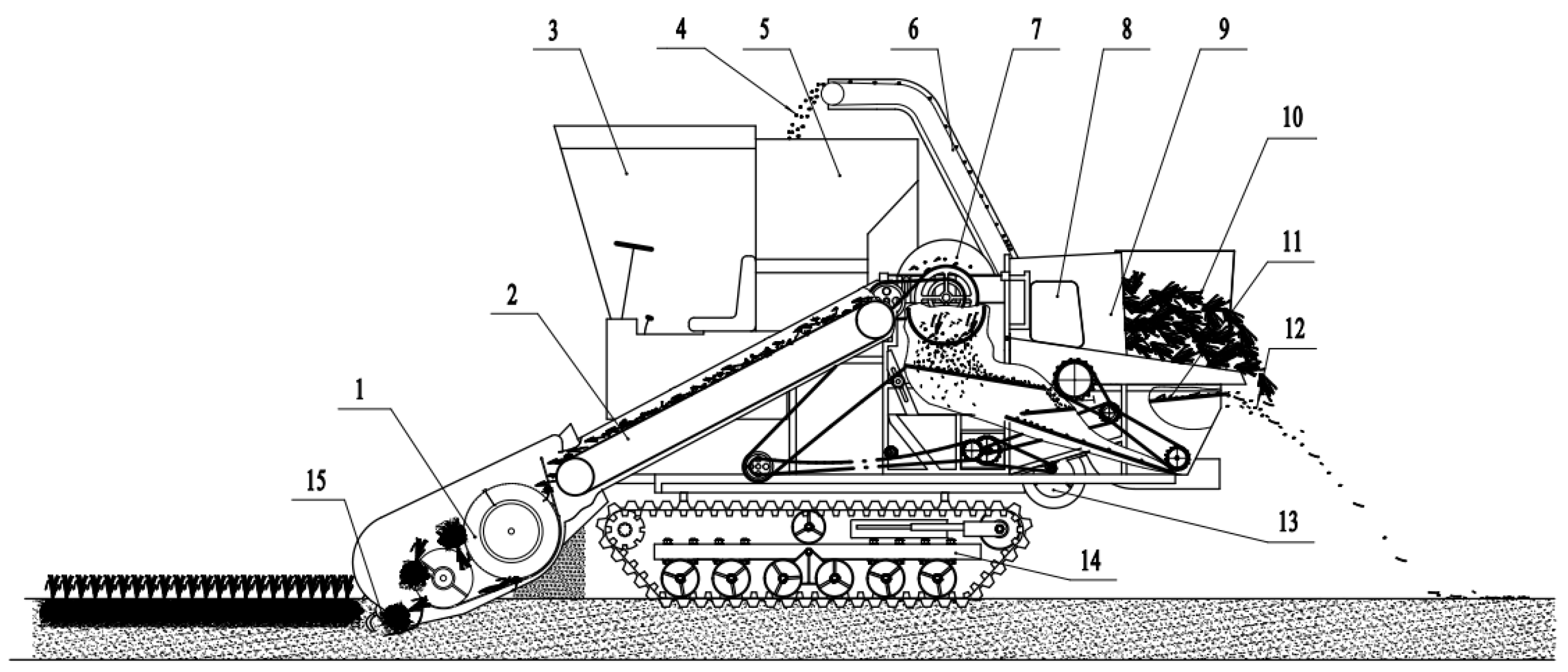
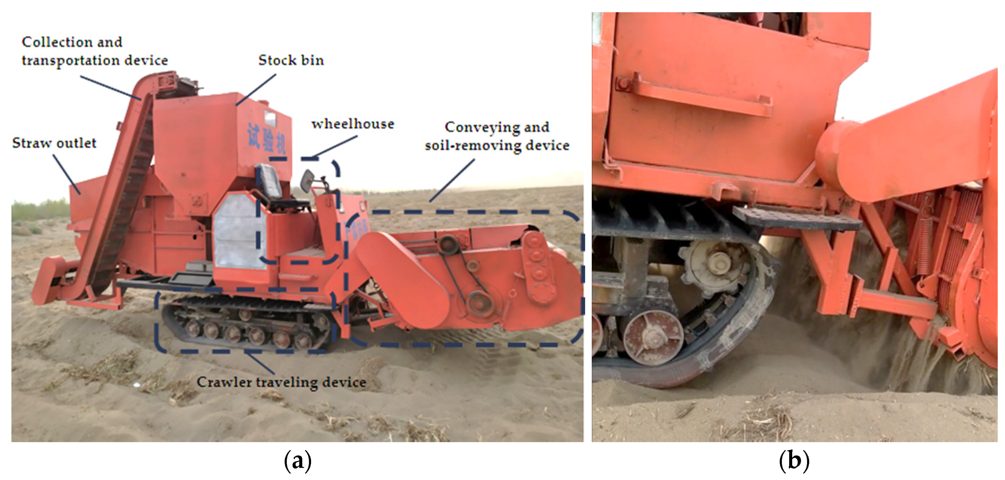
2.1. Structure and Working Principle of Tiger Nut Harvester

The project team proposed that the tiger nut harvester be mainly composed of rotary tillage digging device, conveying and soil-removing device, scraper lifting device, threshing device, cleaning device, stock bin, crawler walking device, etc., as shown in Figure 1.
In the harvester’s operation process, the crawler traveling device effectively ensures traveling performance in the sand. The digging device digs a mixture of tiger nuts, roots, and a large amount of sandy soil and throws it to the conveying and soil-removing device, removing most of the sandy soil in the mixture. The scraper lifting device then transports the mixture of tiger nuts and roots containing a small amount of sandy soil to the threshing device. After threshing, whole tiger nuts and a small part of the roots fall into the cleaning device, with most of the roots being discharged from the straw outlet. The mixture of tiger nuts and fibrous roots is discharged from the rear end of the vibrating screen through the combined action of the fan and vibrating screen, and the tiger nuts are transported by the collection and transportation device to the stock bin.

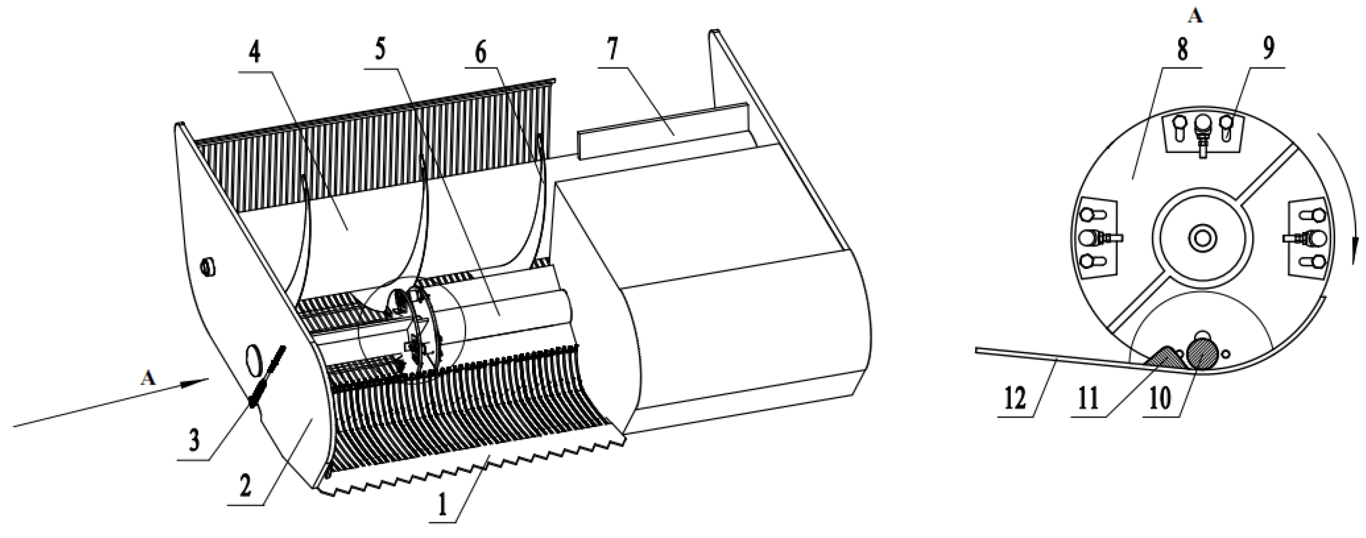
2.2. Structure and Working Principle of Conveying and Soil-Removing Device

The conveying and soil-removing device is mainly composed of a feed scraper, feed scraper shaft, spiral blade, spiral shaft, bar screen, vibration exciter, vibratory element, vibration plate, regulating port, return spring, discharge scraper, frame, etc. Four vibration exciters are averagely arranged in the radial direction of the feed scraper shaft. The vibratory element is installed on the bar screen, which is connected with the frame through the return spring. The structure is shown in Figure 2.
During the operation of the tiger nut harvester, the combination of the rotary tillage digging device and the fixed digging shovel will throw the excavated tiger nuts, roots, and a large amount of sandy soil mixture to the feed scraper, which will then throw the mixture to the screw conveyor. In this process, the feed scraper shaft drives the vibration exciter to rotate, and the vibration exciter contacts with the vibratory element, forcing the bar screen to move away from the vibration exciter. The return spring then reacts to the movement of the bar screen to complete the reciprocating movement. The mixture of tiger nuts, roots, and sandy soil is in a loose state under the vibration of the bar screen, and the sandy soil falls to the ground in the gaps in the grid sieve to complete the removal operation. The mixture moves along the circumferential direction of the spiral blade and in the axial direction to the end under the thrust of the spiral blade. A discharge scraper is arranged at the end of the spiral shaft to throw the tiger nuts, the roots, and a small amount of soil to the scraper lifting device, thereby completing the tiger nut conveyance operation.

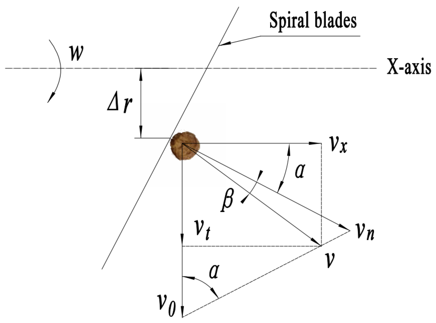
2.3. Analysis of Conveyance Velocity of Tiger Nut

During the operation process of the screw conveyor, the tiger nuts, roots, and sandy soil mixture move upwards along the circumferential direction of the spiral blade under a pushing action. When the mixture reaches a certain position, it collapses downward and flows in the axial direction at the same time. The movement process is required to improve the tiger nut conveyance efficiency; therefore, the tiger nut conveyance conditions are analyzed. The changes in radial velocity and axial velocity of the tiger nuts in the spiral conveyance process are examined. During the operation, the spiral conveying shaft rotates around the x-axis at a constant speed. Taking any tiger nut particle, the movement state of the particle at a distance from the center of the spiral shaft and on the surface of the spiral blade is analyzed and a variable velocity movement is performed under the push of the spiral blade. The velocity analysis is shown in Figure 3.
According to the velocity analysis in the figure, the component vx of the tiger nut particle velocity in the axial direction is:
v x = v cos ( α + β )
where α is the helix angle (°), β denotes the friction angle between the particles and the helicoid (°), vx represents the axial velocity of particle (m/s), and v stands for the resultant velocity of the particle (m/s).
{ v = v n cos β v n = v 0 sin α
where v0 is the implicated velocity of the particle (m/s) and vn represents the vertical velocity of the particle and the spiral blade (m/s).
From the above analysis, when there is no friction, the particle velocity is vn. When there is friction, the particle velocity will become v after the deflection of β in the direction:
v 0 = r w = π n 30 S 2 π t g α = S 60 t g α
where r is the distance from the particle to the center of the spiral axis (mm), w refers to the spiral speed (r/min), and t denotes the conveyance time (s).
At the same time, because f = tanβ, and considering the maximum linear velocity at the edge of the spiral blade, the critical principle is applied Δr = r. Substitute Equations (2) and (3) into Equation (1) to obtain:
v x = S n 60 cos 2 α ( 1 f t g α )
During the calculation, it can be seen that:
{ cos α = 1 1 + ( S 2 π r ) 2 tan α = S 60 t g α
According to Equations (4) and (5), it can be found that:
v x = S n 60 1 f S 2 π r ( S 2 π r ) 2 + 1
According to the same calculation method, the radial velocity of the particle can be obtained:
v t = S n 60 S 2 π r + f ( S 2 π r ) 2 + 1
It can be seen from Equations (6) and (7) that the axial velocity and radial velocity of tiger nut particle are both related to the rotating speed of the spiral shaft. Therefore, based on the determination of the structural parameters of the spiral auger, further research on the rotating speed is required, with the critical condition being that the axial velocity is greater than the radial velocity to ensure the tiger nut conveyance efficiency.

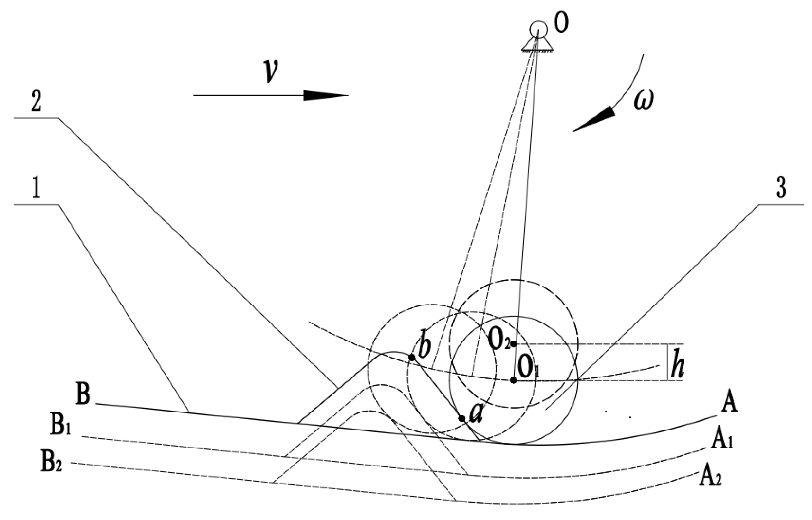
2.4. Analysis of Bar Screen Motion Process

The machine travels at speed v, the vibration exciter interacts with the vibratory element when rotating, and the vibratory element and the bar screen are welded and fixed together, forcing the bar screen to move, as shown in the Figure 4. The adjusting hole can adjust the position of the vibration exciter between point O1 and point O2, and the adjustment range is h, which can adjust the values of different amplitudes. During the contact between the vibration exciter and the vibratory element, the vibration exciter makes a circular motion with point O as the center, and the contact process with the vibratory element is arc length ab. The contact starts at point a, the bar screen starts to move towards position A1B1, and the amplitude begins to increase gradually. When reaching the highest point b, the bar screen reaches the maximum limit position A2B2 and the amplitude reaches the maximum value. Therefore, the distance between AB and A2B2 is the amplitude variation range of the bar screen. When the vibration exciter leaves point b, the vibratory element loses force, the bar screen returns from position A2B2 to AB under the tension of the return spring, and the next vibration exciter repeats the previous process to realize the reciprocating motion of the bar screen.

2.5. Simulation and Analysis of Conveying and Soil-Removing Process

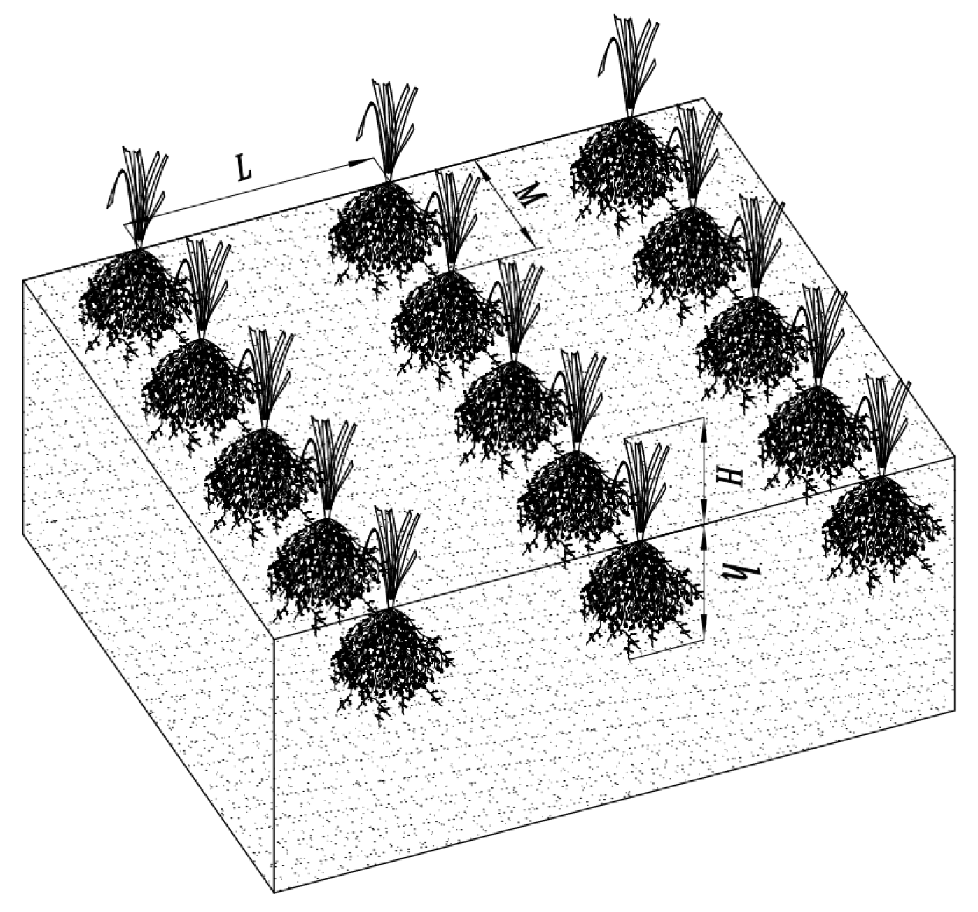
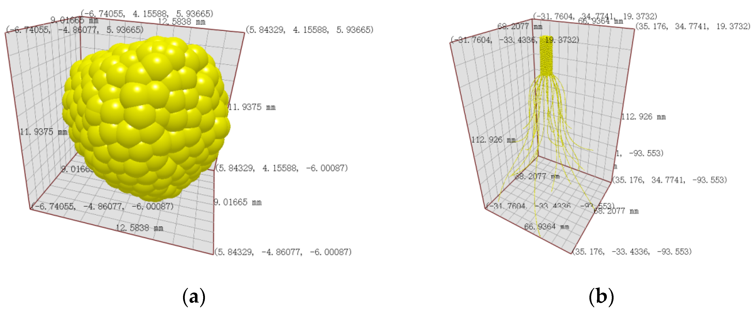
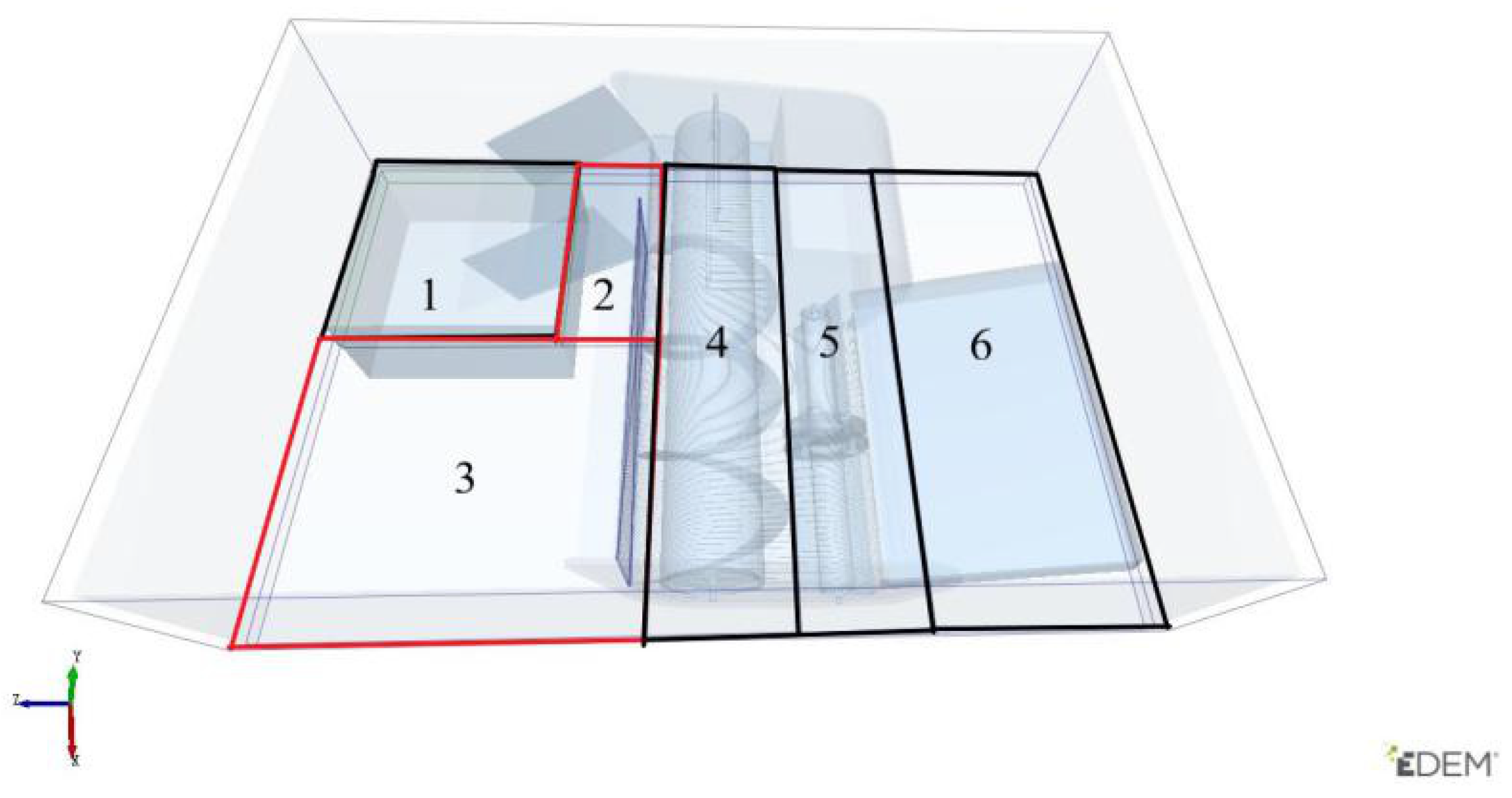
2.5.1. Physical Modeling

The sandy soil, tiger nuts, and roots used in the experiment were sampled from the 54th Regiment of the 3rd Division, Xinjiang. The planting pattern is shown in Figure 5. The planting method was: flat ground, planting spacing M of 35–40 cm, row spacing L of 35–40 cm, stubble height H of 8–10 cm, and growth depth h of 10–12 cm. The sandy soil particle with a radius of 1.5 mm was modeled as a single ball. According to a previous determination, the average size of three axes of tiger nut particle is 10.89 mm; the average length and diameter of the main root of tiger nuts are 53.75 mm and 6.38 mm, respectively; and the average diameter and length of fibrous roots are 0.36 mm and 67.43 mm, respectively. SolidWorks software was used for the three-dimensional modeling of a tiger nut particle and root saved in IGS format. The model was imported into EDEM software, and a multi-ball model was used for filling. A Hertz–Mindlin non-sliding contact model was used between balls [26,27,28], and the simulation models are shown in Figure 6. In addition, to facilitate the simulation calculation, the parts that were irrelevant to the conveying and soil-removing device were removed [29].

2.5.2. Simulation Parameter Setting

The intrinsic factors (Poisson’s ratio, shear modulus, etc.) and basic contact parameters (collision coefficient of restitution, static friction coefficient, and rolling friction coefficient) of sandy soil particles, tiger nuts, and the conveying and soil-removing device geometry were set. In the process of simulation parameter setting, the intrinsic factors of tiger nuts and basic contact parameters between tiger nuts and between tiger nuts and geometry were determined via calibration [30]. The intrinsic parameters of sandy soil and the contact parameters between sandy soil and tiger nuts and between sandy soil and geometry were obtained through reference [31,32,33]. The geometry material was steel, and the intrinsic parameters of geometry were obtained through reference [34,35]. See Table 1 and Table 2 for the simulation parameter setting. A Hertz–Mindlin non-sliding contact model was used as the contact model between tiger nut, root, and sandy soil particle and between them and geometry [36,37].
The generation planes of tiger nut particle, tiger nut root, and sandy soil particle were set at the feeding inlet of the conveying and soil-removing device, and the property was set as virtual. At the outlet of the device, a hexahedral box with the top surface removed was set for collecting sandy soil, tiger nuts, and root stock from the discharge scraper. According to the planting mode of tiger nuts and the working width and depth, the mass ratio of the tiger nuts, root, and sandy soil fed into the conveying device was measured as 1:1.66:156.25. Considering the simulation speed, the mass of sandy soil particles was set as 25 kg, the quantity of tiger nut particles was set as 20 (160 g), the quantity of tiger nut roots was set as 5 (265.6 g) with random generation location, the Rayleigh time step was set as 29%, and a simulation process duration of 12 s was determined.
After simulation was completed, the vibratory sandy soil removal process was divided according to net region into six regions: Region 1 was the sandy soil discharge volume from the discharge scraper transportation to the hexahedral box; Region 2 was the sandy soil discharge volume of the discharge scraper and grid screen; Region 3 was the radial sandy soil discharge volume of the spiral blade; Region 4 was the sandy soil discharge volume below in the spiral conveyer conveyance process; Region 5 was the sandy soil discharge volume of the feed scraper; and Region 6 was the sandy soil discharge volume at the feeding inlet. See Figure 7 for the schematic diagram.

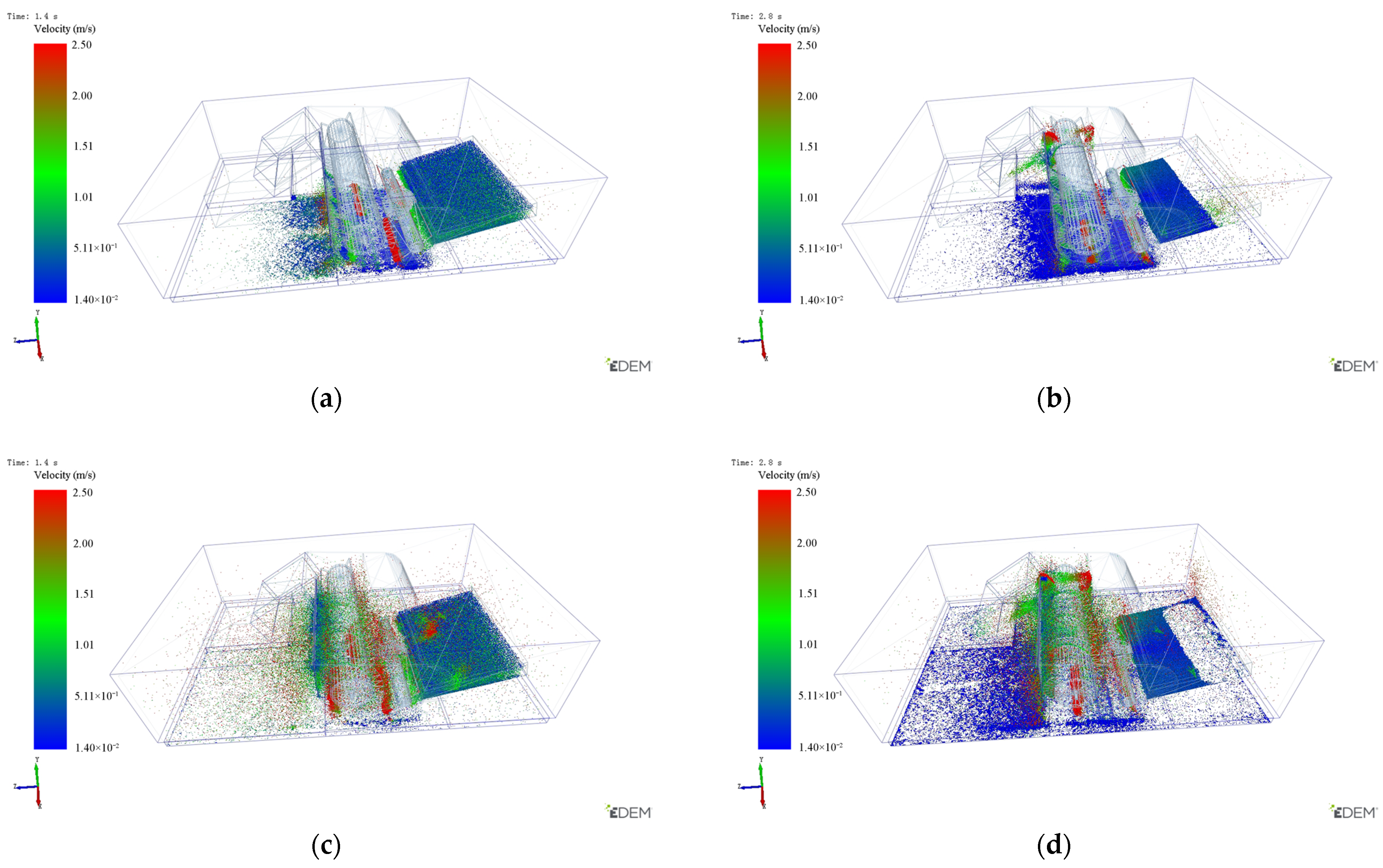
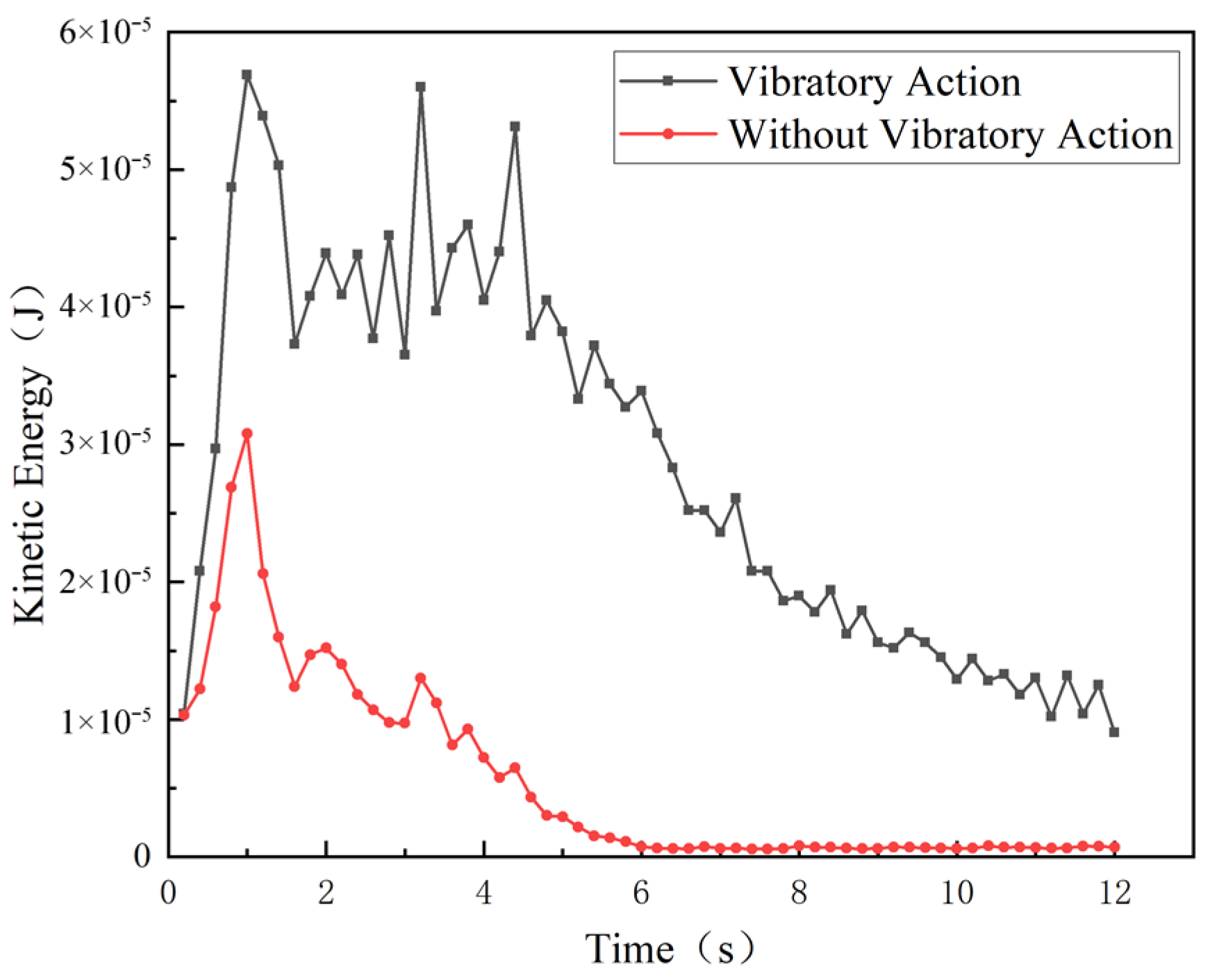
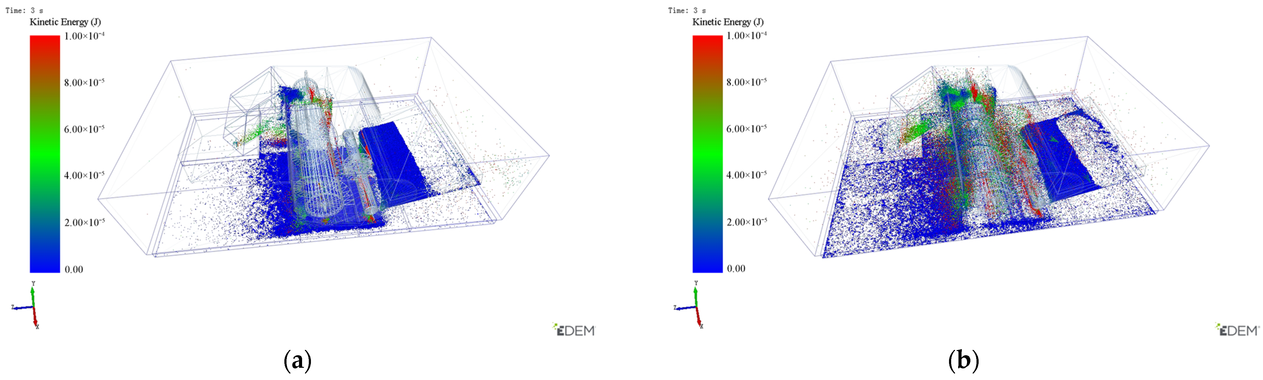
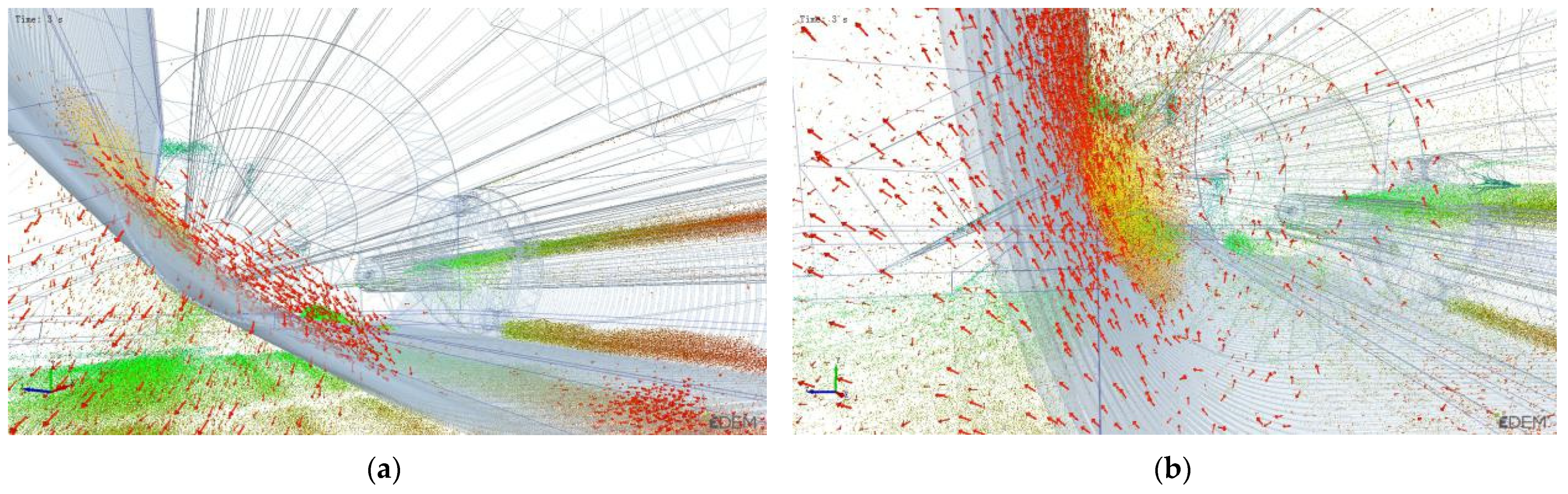
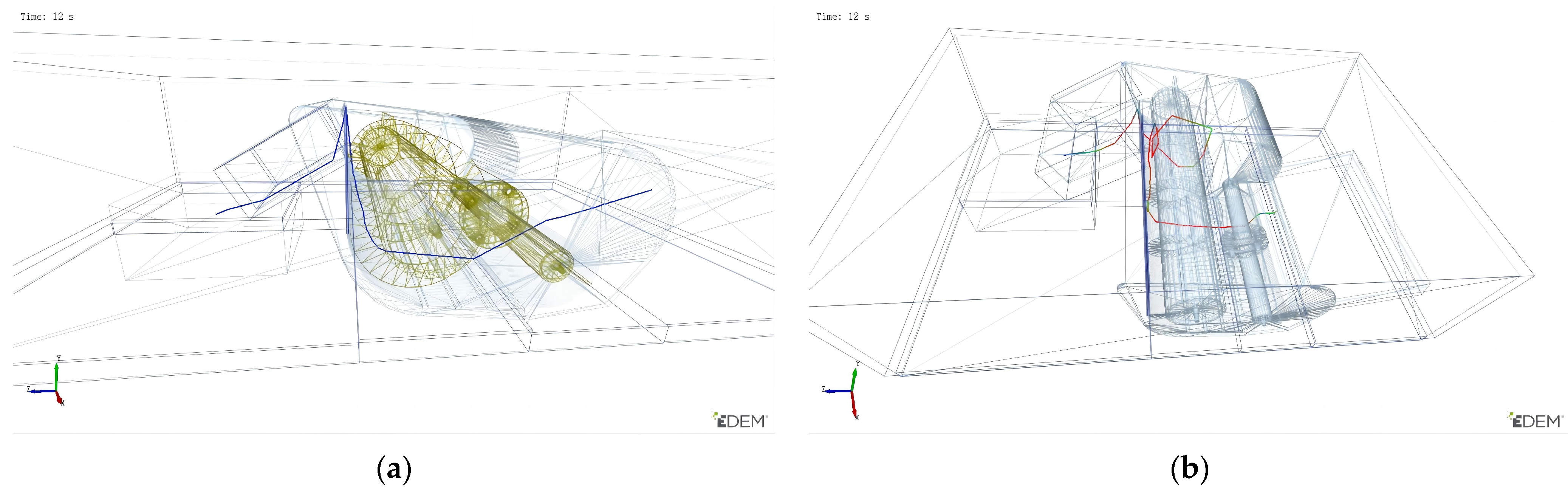
2.5.3. Contrastive Analysis of Sandy Soil Removal Process Simulation with and without Vibratory Action

To verify the reliability of the simulation analysis using EDEM software, a contrastive analysis of the conditions with and without vibration forces during the operation of the conveying and soil-removing device was carried out. The sandy soil feed quantity, spiral speed, and other factors had a fixed value; the vibration amplitude, vibration frequency, and other factors were variables in the simulation. To make clear the motion state of the sandy soil with and without vibratory action, velocity simulation pictures at 1.4 s and 2.8 s in the operating process under the two conditions were extracted, among which Figure 8a,b show the sandy soil removal process without vibratory action and Figure 8c,d display the sandy soil removal process with vibratory action. Sandy soil velocity variation is represented by color bars, among which the color changing from blue to green and then to red means that the sandy soil velocity increases. As shown in the figures, sandy soil is principally blue at 1.4 s without vibratory action, indicating a low velocity, with the discharged sandy soil concentrated in Regions 4 and 5. Sandy soil is principally green with vibratory action, indicating a low velocity, with the discharged sandy soil concentrated in Regions 3 and 4. At 2.8 s, the discharge distance of the sandy soil in Region 3 with vibratory action is longer than that without vibratory action, and the discharged sandy soil is loose in the former conditions and in a stacked state in the latter conditions. Under such conditions, the subsequent feeding of the tiger nut, root, and sandy soil mixture will result in a late reset of the reset spring and an easy blockage in the geometry, which are both unfavorable for stable and continual operation. Meanwhile, the sandy soil is in a stacked state without vibratory action when delivered in geometry, which will not effectively destroy the mixture structure during delivery and is detrimental to the separation of the tiger nut root from the sandy soil, subsequently causing an increase in sandy soil quantity after the tiger nut enters the threshing device and severely influencing threshing quality. In summary, the device can be used to finish the sandy soil removal operation under two such conditions, but for constant feed quantity, the device with vibratory action can accomplish a greater sandy soil removal effect, achieve superior sandy soil removal distribution quality, and ensure better machine stability and continuity than that without vibratory action. This conclusion is consistent with the results of Xie’s study [38].
Combined with the sandy soil particle velocity analysis results, the vibratory action ensures that the sandy soil particles maintain an active flow process in the geometry, extract kinetic energy from the sandy soil particle group, and further analyze the change in sand particle flow velocity. Figure 9 shows that the kinetic energy change trend is generally the same—increasing first, then maintaining in a certain numerical range, and finally decreasing. In the case of vibration, the kinetic energy value remains stable in the range of 1 s to 4 s, gradually decreasing after 4 s. In the case of no vibration, the kinetic energy value remains stable in the range of 1.5 s to 3.5 s, gradually decreasing and approaching 0 after 3.5 s. The kinetic energy of the sandy soil particles with vibration action is higher than that without vibration action. To observe the kinetic energy change more clearly, the total kinetic energy of the sandy soil particles at 3 s under the two conditions was extracted, as shown in Figure 10. Setting the kinetic energy range to be the same, the flow energy variation is represented by color bars. Figure 10a shows the sandy soil removal process without vibratory action. Most of the sandy soil particles in the geometry are blue in color, and a few are green. Figure 10b displays the sandy soil removal process with vibratory action. Most of the sandy soil particles in the geometry are green, and a few are red. The red particles are distributed between the bar screen and the spiral conveying blade. This may be due to the reciprocating vibration force exerted by the bar screen on the particles, with the particles being pushed and centrifuged by the spiral blade at the moment of being bounced up, resulting in an increase in particle flow kinetic energy. At the same time, the color of the sandy soil particles at the discharge outlet is mostly green under the two conditions due to the same rotation speed of the discharge scraper and the same conveyance speed of the sandy soil particles, so the particle flow energy tends to be consistent. The results show that the total kinetic energy of the particles with vibration is significantly higher than that without vibration, which is consistent with the velocity analysis results.
To understand the movement of the sandy soil particles in the geometric body more intuitively, a position change diagram of the sandy soil particles under the double action of grid screen and spiral conveying blade at 3 s was extracted, as shown in Figure 11, and in which Figure 11a displays the sandy soil removal process without vibratory action. It can be seen from Figure 11a that the sandy particle flow moves downward along the screen surface. This may be because the sandy soil particle flow first moves upward along the screen under the action of only the thrust and centrifugal force of the spiral blade. At the moment the force disappears, the sandy soil particles fall to the ground through the bar screen under their own gravity, and most of the sand is discharged below the bar screen. Figure 11b shows the sandy soil removal process with vibratory action. The sandy soil particle flow moves upward along the screen surface, which is probably because the sandy soil particle flow is forced by the reciprocating vibration of the screen. The particles are pushed and centrifuged by the spiral blade at the moment of being bounced up, making the particles pass through the screen quickly with an initial velocity. Due to the initial velocity of the particles, most of the sandy soil is discharged behind the screen. It can be seen from the comparison chart that the active state of the particles with vibration is significantly higher than that without vibration, and the sand-blocking phenomenon can be avoided under the bar screen, which is conducive to the sand removal operation. This conclusion is consistent with the above velocity and kinetic energy analysis results.
Through the above analysis, it can be seen that vibratory sandy soil removal is the better operation mode in the tiger nut harvesting process. Therefore, the simulation of vibratory sand removal was analyzed. The sandy soil discharge volume from large to small is as follows: Region 3, which is the radial sandy soil discharge volume of the spiral blade; Region 4, which is the sandy soil discharge volume below in the spiral conveyer conveyance process; Region 2, which is the sandy soil discharge volume of the discharge scraper and grid screen; Region 5, which is the sandy soil discharge volume of the feed scraper; and Region 6, which is the sandy soil discharge volume at the feeding inlet. The sandy soil discharge volume of the former three regions is approximately 71% of the total discharge volume, indicating that sandy soil can be separated and discharged when the spiral conveyer is used for conveying tiger nuts, roots, and sandy soil. The weight of the sandy soil discharged is greatest in Region 3, which is good for the device discharge volume and prevents contact of the bar screen with the ground and bar screen blockage caused by too much sandy soil being discharged.
We extracted any movement locus of tiger nuts and roots with vibratory action at the end of the simulation. Figure 12 shows that tiger nuts and roots will appear at the feeding inlet and go through the feed scraper, spiral blade, and discharge scraper over time, ultimately ending in the discharge port, indicating that vibratory action can achieve the separation of the sandy soil and effectively convey the tiger nuts and roots.

2.6. Simulation Test Design

The test was designed in accordance with Box–Behnken central composite design theory to analyze the influence of different spiral speeds, vibration amplitudes, and vibration frequencies on the sandy soil removal rate and the variation coefficient of the sandy soil removal velocity of the vibratory sandy-soil-removing device. The level range of factors was determined according to the preliminary experiment. Sandy soil cannot be separated adequately if the spiral speed is too high, as this results in an increased sandy soil volume in the downstream lifting and conveying device and is detrimental to the threshing and separation operation. If the spiral speed is too low, the conveyance efficiency is lowered, although the sandy soil separation effect is achieved. According to the characteristics of low water content and good fluidity of sandy soil planted with tiger nuts, the high-frequency, low-amplitude vibration scheme is selected. When the vibration frequency and amplitude are too high, it can provide a large vibration force, destroying the structural form of the tiger nut root and sandy soil mixture, and maximizing the quality of sand removal. However, it is easy to cause the phenomenon whereby the vibrating screen is not reset in time, which leads to the decline in the stability of sand removal. Based on the analysis of the single factor pre-test results, the spiral speed range is 100–120 r/min, the amplitude range is 5–15 mm, and the vibration frequency is 10–12 Hz. The test factors and levels are shown in Table 3.

2.7. Evaluation Index

The conveyance efficiency is taken as the evaluation index describing the tiger nut conveyance performance. The ratio of the average velocity of tiger nuts in the spiral conveyance to the axial velocity of the spiral blade is taken as the tiger nut conveyance efficiency. It is calculated according to Equation (8):
{ Y 1 = ν 0 ν x × 100 % v x = n S 60
where Y1 is the tiger nut conveyance efficiency (%), v0 represents the average velocity of the tiger nuts (m/s), and vx is the axial velocity of the spiral blade (m/s).
The performance of the vibratory sandy-soil-removing device is described using the sandy soil removal rate as the evaluation index. It is calculated according to Equation (9) when the target and actual sandy soil discharge volume are determined:
Y2 = (M0/M) × 100%
where Y2 is the sandy soil removal rate (%); M0 stands for the actual sandy soil discharge volume, which is the sum of the sandy soil discharge volumes of Regions 2, 3, 4, 5, and 6 (kg); and M represents the target sandy soil discharge volume (25 kg).
The stability of the sandy soil removal velocity is described by the coefficient of variation. The smaller the coefficient of variation, the better the stability of the sandy soil removal velocity. This is calculated according to Equation (10):
Y3 = (S/V) × 100%
where Y3 is the variable coefficient, S represents the standard deviation of samples, and V denotes the mean value of samples.

2.8. Field Test Method

The tiger nut, root, and sandy soil mixtures were fed into the screw conveyor, and the continuous passing time of the tiger nut through the screw conveyor was recorded. The actual axial velocity of the tiger nut was calculated by the length of the screw auger, and the conveyance efficiency of the tiger nut was calculated according to Equation (8).
In addition, the total mass of sandy soil was calculated within a length of 5 m of the test area as the target sandy soil discharge volume, and the total mass of sandy soil was collected and weighed in the conveying device and the threshing device. The difference between the target sandy soil discharge volume and the total mass weighed was used to obtain the actual sandy soil discharge volume, with the sandy soil removal rate calculated according to Equation (9).

3. Results and Discussion

3.1. Analysis of the Simulation Test Results

The three-factor and three-level test was designed using spiral speed, vibration amplitude, and vibration frequency as the factors and the conveyance efficiency, sandy soil removal rate, and variation coefficient of sandy soil removal velocity as the evaluation index. The test programs included 17 test points, among which 12 test points were analysis factors, with five zero-estimation errors. See Table 4 for the design scheme and results.
The variance analysis of the test results in Table 4 was conducted using Design-Expert 8.0.6 software. See Table 5 for the analysis results. The regression model equation was calculated between the evaluation indexes of conveyance efficiency, sandy soil removal rate, and variation coefficient of sandy soil removal velocity and the independent variables of spiral speed, vibration amplitude, and vibration frequency.
Y1 = 76.99 − 10.67X1 − 2.18X2 − 5.19X3 − 4.35X1X2 − 1.72X1X3 + 0.77X2X3
2.32X12 − 9.10X22 − 7.05X32
Y2 = 84.02 − 2.5X1 − 7.84X2 + 2.98X3 − 2.52X1X2 + 0.03X1X3 + 0.61X2X3 − 5.10X12
− 4.46X22 − 7.51X32
Y3 = 3.56 − 0.55X1 − 0.44X2 + 0.86X3X1X2 − 0.55X1X3 − 0.23X2X3 + 0.76X12 +
0.13X22 + 0.58X32
The significance of the index influence of various variables in the regression equation was judged by the F value, the lower probability p, and the higher significance of the corresponding variables [39]. The regression model p value is less than 0.0001, indicating that the model is extremely significant. The lack-of-fit p value is 0.0525 and more than 0.05; that is, the lack of fit is not significant, indicating that it is within the experiment range and that the prediction value of the regression model has a good degree of fit with the actual value. The determination coefficient of conveyance efficiency, sandy soil removal rate, and variation coefficient of sandy soil removal velocity are 0.9810, 0.9843, and 0.8893, respectively, indicating that the prediction value is highly correlated to the actual value and that the model can be used for the analysis and prediction of the experiment index.

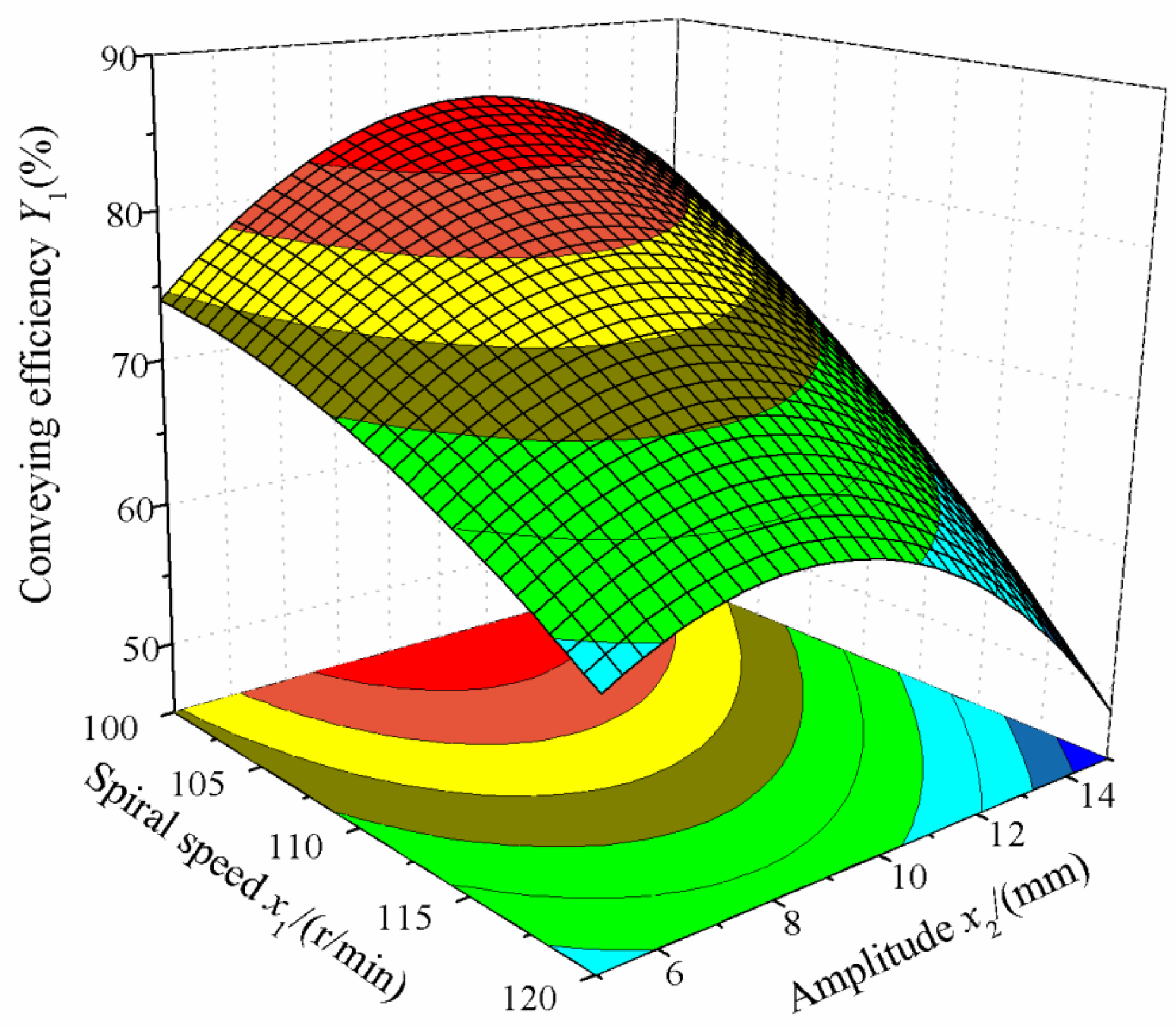
3.1.1. Influence of Various Factors on Conveyance Efficiency

In the regression equation, the absolute value of the factor coefficient determined the influence degree of the test index. According to regression Equation (11) and Table 5, factors X1, X3, X1X2, X22, and X32 are extremely significant, factor X2 is significant, and the other factors are not significant in the conveyance efficiency model. The influence and importance of various factors on conveyance efficiency from high to low are: spiral speed X1, vibration frequency X3, and vibration amplitude X2. To observe the influence law more clearly, the three-dimensional response surface was extracted, as shown in Figure 13. It shows that when the amplitude is constant, with the increase in spiral speed, the conveyance efficiency will increase slowly and then decrease slowly. This is probably due to the fact that as the spiral speed increases, the tiger nut axial velocity also increases. When the spiral speed is too great, the tiger nut will move in a circle with the spiral blade, leading to a decrease in the conveyance efficiency. When the spiral speed is constant, with the increase in amplitude, the conveyance efficiency will increase and then decrease. This is possibly due to the fact that when the amplitude is too large, the tiger nut will move back and forth with the bar screen, reducing contact with the spiral auger.

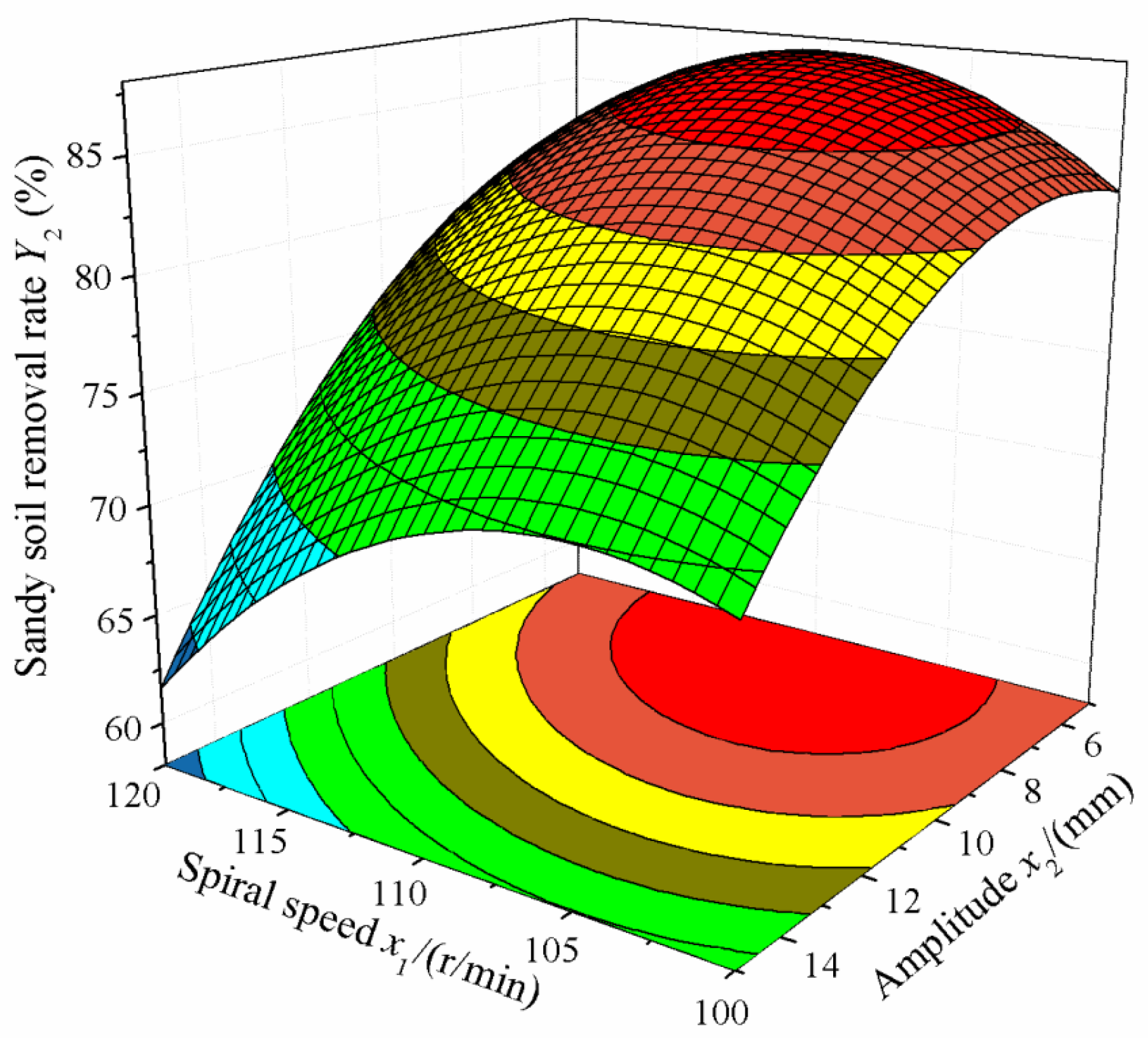
3.1.2. Influence of Various Factors on Sandy Soil Removal Rate

According to regression Equation (12) and Table 5, factors X1, X2, X3, X12, X22, and X32 are extremely significant; factor X1X2 is significant; and the other factors are not significant in the sandy soil removal rate model. The influence and importance of various factors on the sandy soil removal rate from high to low are: vibration amplitude X2, vibration frequency X3, and spiral speed X1. To observe the influence law more clearly, a three-dimensional response surface was extracted, as shown in Figure 14. It shows that when the spiral speed is at the 0 level, the sandy soil removal rate will increase slowly and then decrease slowly as the vibration amplitude increases. This is probably due to the facts that the vibration amplitude determines the vibratory action and that the sandy soil removal rate will increase with increasing vibration amplitude. However, if the vibration amplitude is too high, the reset spring will not reset the bar screen in a timely manner and its vibratory action will decrease for the sandy soil, resulting in stacked sandy soil on the bar screen and a decrease in the sandy soil removal rate. When the vibration amplitude is at the 0 level, the sandy soil removal rate will increase slowly and then decrease rapidly as the vibration amplitude increases. This is possibly because the spiral speed correlates to the axial and tangential speed in the sandy soil conveyance process. If the tangential speed increases, sandy soil will be thrown out along the spiral blade and be discharged out of the machine via the bar screen, so the sandy soil removal rate will rise. However, if the tangential speed is too high, sandy soil cannot be thrown out in a timely manner and can only move in the axial direction, which will result in low conveyance efficiency, stacked sandy soil in the machine, and a decrease in the sandy soil removal rate.

3.1.3. Influence of Various Factors on Variation Coefficient of Sandy Soil Removal Velocity

According to regression Equation (13) and Table 5, factor X3 is extremely significant; factors X1, X1X2, and X12 are significant; and the other factors are not significant in the variation coefficient of the sandy-soil-removing velocity model. The influence and importance of various factors on the sandy soil removal rate from high to low are: vibration frequency X3, spiral speed X1, and vibration amplitude X2. To observe the influence law more clearly, a four-dimensional slice and three-dimensional response surface were extracted, as shown in Figure 15. It can be seen that with the increase in spiral speed, the variation coefficient first decreases and then increases and that the surface is steep. When the spiral speed is approximately 110 r/min, the variation coefficient reaches the minimum. When the spiral speed takes a certain value, with the increase in amplitude, the coefficient of variation first decreases and then increases, and the surface changes gently, indicating that the spiral speed has a significant effect on the coefficient of variation compared with the amplitude.

3.1.4. Operating Parameter Optimization

To find the optimal combination of various factors, the maximum values of conveyance efficiency and sandy soil removal rate, and the minimum value of the variation coefficient of sandy soil removal velocity were calculated using the optimization function provided in the Design-Expert software:
{ M a x Y 1 ( x 1 , x 2 , x 3 ) M a x Y 2 ( x 1 , x 2 , x 3 ) M i n Y 3 ( x 1 , x 2 , x 3 )
{ 100 x 1 120 5 x 2 15 10 x 3 12
The optimal influence factor parameter combination is a spiral speed of 107 r/min, a vibration amplitude of 8.5 mm, and a vibration frequency of 10.7 Hz. In this combination, the conveyance efficiency is 80.39%, the sandy soil removal rate is 84.61%, and the variation coefficient of sandy soil removal velocity is 3.6%.

3.2. Field Test Result

To verify the reliability of the optimization results, experimental verification was conducted in October 2020 in the 54th Regiment of the 3rd Division, Xinjiang, as shown in Figure 16. The parameters of tiger nut harvesting are shown in Table 6. During the tiger nut harvesting period, the average moisture content of the sandy soil 15 cm below the ground surface was 4.91%, as measured using a TDR300 soil moisture meter. The working width of the machines was 1.3 m, and the working depth was 15 cm. It was found that the optimal combination of operating parameters for the conveying and soil-removing device is a spiral speed of 107 r/min, a vibration amplitude of 8.5 mm, and a vibration frequency of 10.7 Hz. The experiment was carried out three times, and the average value of the test results was taken. The mean value of the conveyance efficiency was 78.34%, the sandy soil removal rate was 83.42%, and the relative errors with theoretical values were 2.55% and 1.41%, respectively. Under this parameter combination, the tiger nut damage rate was 1.16% and the tiger nut leakage rate was 0.52%. The results showed that the conveying and soil-removing device could meet the tiger nut harvest performance requirements. In addition, in the field test process, the water moisture content of the sandy soil directly affected the sandy soil removal rate index. If the water moisture content of sandy soil is too high, the bar screen gap will be blocked. In future, it will be necessary to further study the water moisture content of sandy soil particle simulation modeling to ensure the accuracy of the simulation test and the field test to determine the best harvest date for tiger nuts.

4. Conclusions

A conveying and soil-removing device that removes sandy soil while conveying tiger nuts was proposed. The factors affecting conveying and soil-removing performance were analyzed, and the two operational processes of the device with and without vibration were numerically simulated using EDEM software. The sandy soil movement velocity changes under the two conditions were compared and analyzed, and the movement tracks of tiger nut particles and tiger nut roots under the conditions of vibration were extracted. The results showed that the vibrating force was more conducive to the completion of the sandy soil removal operation and the effective conveyance of tiger nuts and roots.
The simulation test was carried out using spiral speed, vibration amplitude, and vibration frequency as the independent variables and with tiger nut conveyance efficiency, sandy soil removal rate, and the variation coefficient of sandy soil removal velocity as the dependent variables. A Box–Behnken central composite design was applied for the parameter optimization of the three factors affecting the dependent variables. The test results showed that optimal parameter combination was a spiral speed of 107 r/min, a vibration amplitude of 8.5 mm, and a vibration frequency of 10.7 Hz, under which the theoretical value of the conveyance efficiency was 80.39%, the sandy soil removal rate was 84.61%, and the variation coefficient of the sandy soil removal velocity was 3.6%.
The field experiment conducted to determine the optimal parameter combination showed the conveyance efficiency was 78.34%, the sandy soil removal rate was 83.42%, and the relative errors with theoretical values were 2.55% and 1.41%, respectively. Under this parameter combination, the tiger nut damage rate was 1.16% and the tiger nut leakage rate was 0.52%. The test results showed that the conveying and soil-removing device could meet the tiger nut harvest performance requirements. This study could provide the basis for the design and optimization of a tiger nut harvester.

5. Patents

Qi, J.T.; An, S.G.; Meng, H.W.; Kan, Z.; Ma, C.H.; Chen, S.; Pei, M.H. A conveying and soil-removing device for tiger nut before threshing: ZL202110464650.1[P]. 28 April 2021.

Author Contributions

Conceptualization, data curation, formal analysis, writing—original draft, J.Q.; formal analysis, software, M.P.; conceptualization, funding acquisition, methodology, Z.K.; funding acquisition, writing—review and editing, project administration, H.M. All authors have read and agreed to the published version of the manuscript.

Funding

This research was funded by the local science and technology development under the guidance of the central government, grant number: kc005102, and the project of Engineering Research Center for Production Mechanization of Oasis Special Economic Crop, Ministry of Education, grant number: PMOC2021A03.

Data Availability Statement

The data presented in this study are available on request from the corresponding author.

Conflicts of Interest

The authors declare no conflict of interest.

References

  1. Zhao, X.Q.; Liu, H.; Lu, Z.Y.; Cheng, Y.C.; Zhang, D.J.; Bai, F.F.; Fang, J.; Ren, Y.F. Cultivation technology of windbreak and sand fixation of Cyperus esculentus L. on desertified and degraded land. Mod. Agric. 2019, 6, 12–13. [Google Scholar] [CrossRef]
  2. Oladele, A.K.; Aina, J.O. Chemical composition and functional properties of flour produced from two varieties of tiger nut (Cyperus esculentus). Afr. J. Biotechnol. 2007, 21, 2473–2476. [Google Scholar] [CrossRef] [Green Version]
  3. Wang, R.Y.; Wang, X.S.; Xiang, H. A multi-purpose novel oil crop—Cyperus beans. China Oils Fats. 2019, 44, 1–4. [Google Scholar] [CrossRef]
  4. Qu, P.M.; Cheng, Z.Y.; Long, C.L.; Su, M.H.; Yang, D. Comprehensive development of chufa (Cyperus esculentus L. var. sativus). China Oils Fats. 2007, 9, 61–63. [Google Scholar] [CrossRef]
  5. Liu, X.M.; Liu, Z.H.; Liang, Y.; Xiao, S.P. Development of Multifunctional Harvesting Machine Based on Modular Theory. J. Chin. Agric. Mech. 2012, 5, 47–50. [Google Scholar] [CrossRef]
  6. Sánchez-Zapata, E.; Fernández-López, J.; Angel Pérez-Alvarez, J. Tiger nut commercialization: Health aspects, composition, properties, and food applications. Compr. Rev. Food Sci. Food Saf. 2012, 11, 366–377. [Google Scholar] [CrossRef]
  7. Di, Z.F.; Li, Q.L.; Jiang, W.; Zhang, Z.Q.; Zhang, H.; Li, N.; Cui, Z.K.; Zhou, J. Research advance and perspective of Cyperus esculentus planting and harvesting machinery technology and equipment. J. Shanxi Agric. Univ. 2022, 42, 96–106. [Google Scholar] [CrossRef]
  8. He, X.; Lv, Y.; Qu, Z.; Wang, W.; Zhou, Z.; He, H. Parameters optimization and test of caterpillar self-Propelled tiger nut harvester hoisting device. Agriculture 2022, 12, 1060. [Google Scholar] [CrossRef]
  9. Wanfangdata. Available online: https://d.wanfangdata.com.cn/patent/ChJQYXRlbnROZXdTMjAyMjEyMDcSEENOMjAxODIxMTUxMDUwLlgaCHBiMm4xdWYy (accessed on 30 April 2019).
  10. Wanfangdata. Available online: https://d.wanfangdata.com.cn/patent/ChJQYXRlbnROZXdTMjAyMjEyMDcSEENOMjAyMDEwNzczMDI5LjkaCDUzemxxcmxl (accessed on 9 October 2020).
  11. Wanfangdata. Available online: https://d.wanfangdata.com.cn/patent/ChJQYXRlbnROZXdTMjAyMjEyMDcSEENOMjAxNzEwMTIyMTc0LjkaCGR6aWdnY25z (accessed on 31 March 2017).
  12. Zhao, Q.L.; Chen, X.M.; Xu, S.; Liu, H.B. Application value and research status of its planter and harvester of Cyperus esculentus. Agric. Technol. Equip. 2022, 1, 76–77, 80. [Google Scholar]
  13. Fu, Q.K.; Fu, J.; Chen, Z.; Chen, C.; Ren, L.Q. Optimization of working parameters on soil removal of stover pickup baler by vibration. Trans. Chin. Soc. Agric. Eng. 2018, 34, 26–33. [Google Scholar] [CrossRef]
  14. Wei, Z.C.; Li, H.W.; Su, G.L.; Sun, C.Z.; Liu, W.Z.; Li, X.Q. Development of potato harvester with buffer type potato-impurity separation sieve. Trans. Chin. Soc. Agric. Eng. 2019, 35, 1–11. [Google Scholar] [CrossRef]
  15. Lü, J.Q.; Tian, Z.E.; Wu, J.E.; Yang, Y.; Shang, Q.Q.; Wang, Y.B. Design and experiment on 4U1Z vibrating potato digger. Trans. Chin. Soc. Agric. Eng. 2015, 31, 39–47. [Google Scholar] [CrossRef]
  16. Hu, Z.C.; Chen, Y.Q.; Wang, H.O.; Zhang, H.J.; Xie, H.X.; Tian, L.J. Design and experimental research on vibrating type peanut harvester. Trans. Chin. Soc. Agric. Eng. 2008, 10, 114–117. [Google Scholar] [CrossRef]
  17. Wang, D.W.; Shang, S.Q.; Li, X.; Gao, D.X. Type-L Cleaning Separation Mechanism of Peanut Combine Harvester. Trans. Chin. Soc. Agric. Mach. 2013, 44, 68–74+51. [Google Scholar] [CrossRef]
  18. Zhang, Z.G.; Wang, F.A.; Zhang, Y.C.; Zhang, D.; Tian, R. Design and Experiment of Self-propelled Panax notoginseng Harvester. Trans. Chin. Soc. Agric. Mach. 2016, 47, 234–240. [Google Scholar] [CrossRef]
  19. Liu, J.J.; Song, J.N.; Wang, J.C. Kinematics and Mechanics Research on Vibration Separate Equipment of Garlic Harvesting Machine. J. Hunan Agric. Univ. (Nat. Sci.) 2006, 5, 536–539. [Google Scholar] [CrossRef]
  20. Shahgoli, G.; Fielke, J.; Desbiolles, J.; Saunders, C. Optimising oscillation frequency in oscillatory tillage. Soil Tillage Res. 2009, 106, 202–210. [Google Scholar] [CrossRef]
  21. Rao, N.R.N.V.G.; Chaudhary, H.; Sharma, A.K. Optimal design and analysis of oscillatory mechanism for agricultural tillage operation. SN Appl. Sci. 2019, 1, 1003. [Google Scholar] [CrossRef] [Green Version]
  22. Niyamapa, T.; Salokhe, V.M. Soil disturbance and force mechanics of vibrating tillage tool. J. Terramech. 2000, 37, 151–166. [Google Scholar] [CrossRef]
  23. Xing, X.; Qin, Z.; Cao, S.B.; Feng, X.J. Design of Vibration Device for Yam Harvester. J. Agric. Mech. Res. 2019, 41, 126–130. [Google Scholar] [CrossRef]
  24. Cheng, C.; Fu, J.; Chen, Z.; Ren, L.Q. Effect of vibration parameters of vibrating screen for harvester on adhesion characteristics of threshed mixtures with different moistures. Trans. Chin. Soc. Agric. Eng. 2019, 35, 29–36. [Google Scholar] [CrossRef]
  25. Fu, W.; Chen, H.T.; Kan, Z. Optimizing parameters on vibration breakshovel of radish harvester. Trans. Chin. Soc. Agric. Eng. 2011, 27, 46–50. [Google Scholar] [CrossRef]
  26. Barrios, G.K.P.; Carvalho, R.M.; Kwade, A.; Tavares, L.M. Contact parameter estimation for DEM simulation of iron ore pellet handling. Powder Technol. 2013, 248, 84–93. [Google Scholar] [CrossRef]
  27. Liu, W.Z.; He, J.; Li, H.W.; Li, X.Q.; Zheng, K.; Wei, Z.C. Calibration of Simulation Parameters for Potato Minituber Based on EDEM. Trans. Chin. Soc. Agric. Mach. 2018, 49, 125–135, 142. [Google Scholar] [CrossRef]
  28. Leblicq, T.; Smeets, B.; Vanmaercke, S.; Ramon, H.; Saeys, W. A discrete element approach for modelling bendable crop stems. Comput. Electron. Agric. 2016, 124, 141–149. [Google Scholar] [CrossRef]
  29. Horváth, D.; Poós, T.; Tamás, K. Modeling the movement of hulled millet in agitated drum dryer with discrete element method. Comput. Electron. Agric. 2019, 162, 254–268. [Google Scholar] [CrossRef]
  30. Qi, J.T.; An, S.G.; Kan, Z.; Meng, H.W.; Li, Y.P.; Zhao, X.Y. Discrete element-based calibration of simulation parameters of Cyperus esculentus L. (tiger nut) planted in sandy soil. J. Food Process. Preserv. 2021, 45, e15631. [Google Scholar] [CrossRef]
  31. Ucgul, M.; Fielke, J.M.; Saunders, C. Three-dimensional discrete element modeling of tillage: Determination of a suitable contact model and parameters for a cohesionless soil. Biosyst. Eng. 2014, 121, 105–117. [Google Scholar] [CrossRef]
  32. Ucgul, M.; Fielke, J.M.; Saunders, C. Defining the effect of sweep tillage tool cutting edge geometry on tillage forces using 3D discrete element modeling. Inf. Process. Agric. 2015, 2, 130–141. [Google Scholar] [CrossRef] [Green Version]
  33. Zhang, R.; Han, D.L.; Ji, Q.L.; He, Y.; Li, J.Q. Calibration Methods of Sandy Soil Parameters in Simulation of Discrete Element Method. Trans. Chin. Soc. Agric. Mach. 2017, 48, 49–56. [Google Scholar] [CrossRef]
  34. Dun, G.Q.; Yu, C.L.; Yang, Y.Z.; Ye, J.; Du, J.X.; Zhang, J.T. Parameter simulation optimization and experiment of seed plate type hole for soybean breeding. Trans. Chin. Soc. Agric. Eng. 2019, 35, 62–73. [Google Scholar] [CrossRef]
  35. Hao, J.J.; Nie, Q.L.; Ma, L.P.; Li, J.C.; Song, Y.H.; Long, S.F. Development of cone disc type shelling mechanism for pcanut seeds. Trans. Chin. Soc. Agric. Eng. 2020, 36, 27–34. [Google Scholar] [CrossRef]
  36. Niu, K.; Yuan, Y.W.; Luo, M.; Liu, Y.C.; Lu, C.X.; Fang, X.F. Design and experiment of potato metering device with double-deck seed tank. Trans. Chin. Soc. Agric. Eng. 2016, 32, 32–39. [Google Scholar] [CrossRef]
  37. Lei, X.L.; Liao, Y.T.; Liao, Q.X. Simulation of seed motion in seed feeding device with DEM-CFD coupling approach for rapeseed and wheat. Comput. Electron. Agric. 2016, 131, 29–39. [Google Scholar] [CrossRef]
  38. Xie, S.; Wang, C.; Deng, W. Experiment of a swing separating sieve on a potato digger. Eng. Agrícola 2019, 39, 548–554. [Google Scholar] [CrossRef] [Green Version]
  39. Dong, C.W.; Zhao, J.W.; Zhu, H.K.; Yuan, H.B.; Ye, Y.; Chen, Q.S. Parameter optimization of black tea fermentation machine based on RSM and BP-AdaBoost-GA. Trans. Chin. Soc. Agric. Mach. 2017, 48, 335–342. [Google Scholar] [CrossRef]
Figure 1. Structure diagram of tiger nut harvester: (1) conveying and soil-removing device; (2) scraper lifting device; (3) cab; (4) tiger nut; (5) stock bin; (6) collection and transportation device; (7) threshing device; (8) oil tank; (9) straw outlet; (10) tiger nut root; (11) cleaning device; (12) fibrous root; (13) fan; (14) crawler traveling device; (15) rotary tillage digging device.
Processes 11 00067 g001
Figure 2. Diagram of conveying and soil-removing device: (1) fixed digging shovel; (2) frame; (3) return spring; (4) spiral shaft; (5) feed scraper; (6) spiral blade; (7) discharge scraper; (8) vibration plate; (9) regulating port; (10) vibration exciter; (11) vibratory element; (12) bar screen.
Processes 11 00067 g002
Figure 3. Tiger nut velocity analysis.
Processes 11 00067 g003
Figure 4. Schematic diagram of excitation process: (1) bar screen; (2) vibratory element; (3) vibration exciter.
Processes 11 00067 g004
Figure 5. Planting pattern.
Processes 11 00067 g005
Figure 6. Construction of 3D model: (a) tiger nut model; (b) tiger nut root model.
Processes 11 00067 g006
Figure 7. Vibration process region division.
Processes 11 00067 g007
Figure 8. Velocity simulation comparison diagram: (a) without vibratory action at 1.4 s; (b) without vibratory action at 2.8 s; (c) with vibratory action at 1.4 s; (d) with vibratory action at 2.8 s.
Processes 11 00067 g008
Figure 9. Kinetic energy simulation curve diagram.
Processes 11 00067 g009
Figure 10. Kinetic energy simulation comparison diagram: (a) sandy soil removal process without vibratory action; (b) sandy soil removal process with vibratory action.
Processes 11 00067 g010
Figure 11. Position simulation comparison diagram: (a) sandy soil removal process without vibratory action; (b) sandy soil removal process with vibratory action.
Processes 11 00067 g011
Figure 12. Movement locus: (a) movement locus of tiger nut; (b) movement locus of tiger nut root.
Processes 11 00067 g012
Figure 13. Influence of factor interaction on conveyance efficiency.
Processes 11 00067 g013
Figure 14. Influence of factor interaction on sandy soil removal rate.
Processes 11 00067 g014
Figure 15. Influence of factor interaction on the variation coefficient of sandy soil removal velocity.
Processes 11 00067 g015
Figure 16. Experimental verification: (a) field experiment; (b) sandy soil removal process.
Processes 11 00067 g016
Table 1. Intrinsic parameters.
MaterialPoisson’s RatioDensity (kg/m3)Elasticity Modulus (Mpa)
Sandy soil0.3163829.9
Tiger nut0.4110891.5 × 102
Geometry0.2878502.099 × 103
Table 2. Contact parameters.
a/b/cSandy SoilTiger NutGeometry
Sandy soil0.15/0.8/0.20.15/0.8/0.10.5/0.5/0.1
Tiger nut/0.437/0.48/0.050.454/0.413/0.0675
Geometry///
Note: a indicates coefficient of restitution; b indicates coefficient of static friction; and c indicates coefficient of rolling friction.
Table 3. Test factor and level.
CodeSpiral Speed/(r/min)Amplitude/(mm)Vibration Frequency/(Hz)
–1100510
01101011
11201512
Table 4. Experimental design scheme and results.
No.Spiral Speed X1/(r/min)Amplitude X2/(mm)Vibration
Frequency
X3/(Hz)
Conveyance Efficiency Y1/(%)Sandy Soil Removal Rate Y2/(%)Variation Coefficient of Sandy Soil Removal Velocity Y3/(%)
1–1–1072.6781.984.5
21–1061.4280.444.7
3–11078.4173.546.2
411049.7861.902.4
5–10–181.3870.043.5
610–162.0766.584.2
7–10176.676.196.7
810150.4372.855.2
90–1–170.7878.724.1
1001–163.4859.653.1
110–1156.6883.235.9
1201152.4566.604.0
1300078.5484.703.2
1400075.0283.003.2
1500079.9583.403.8
1600076.4385.103.6
1700075.0283.904.0
Table 5. Variance analysis results of response surface model.
SourceConveyance Efficiency Y1Sandy Soil Removal Rate Y2Variation Coefficient of Sandy Soil Removal Velocity Y3
Sum of SquaresF Valuep-ValueSum of SquaresF Valuep ValueSum of SquaresF Valuep-Value
Model1885.7840.07<0.0001 **1116.848.86<0.0001 **19.556.250.0123
X1910.79174.17<0.0001 **49.919.650.0030 **2.426.960.0335 *
X237.987.260.0309 *491.1193.65<0.0001 **1.534.40.0741
X3215.8041.270.0004 **71.2828.070.0011 **5.9517.110.0044 **
X1X275.5214.440.0067 **25.510.040.0157 *411.50.0116 *
X1X311.762.250.17730.00360.00150.9711.213.480.1044
X2X32.360.450.52361.490.590.46890.20.580.4704
X1222.764.350.0754109.343.040.0003 **2.426.950.0336 *
X22348.4666.64<0.0001 **83.7532.980.0007 **0.0740.210.6588
X32209.1139.990.0004 **237.4793.51<0.0001 **1.434.110.0823
Residual36.60 17.78 2.43
Lack of Fit17.371.200.415614.716.390.05251.925.010.0769
Pure Error19.24 3.07 0.51
Cor Total1922.38 1134.57 21.98
R20.9810 0.9843 0.8893
C.V3.35% 2.10% 13.87%
Note: * = 0.01 < p < 0.05; ** = p < 0.01.
Table 6. Tiger nut harvester parameters.
ItemValue
Overall dimension/mm5750 × 2300 × 3000
Working width/mm1300
Working depth/mm150
Auxiliary power/kW60
Operating speed/km/h0.8~1.3
Disclaimer/Publisher’s Note: The statements, opinions and data contained in all publications are solely those of the individual author(s) and contributor(s) and not of MDPI and/or the editor(s). MDPI and/or the editor(s) disclaim responsibility for any injury to people or property resulting from any ideas, methods, instructions or products referred to in the content.

