Article

Density Functional Theory Study on the Adsorption of Fe(OH)2+ on Kaolinite Surface in Water Environment

1
School of Resource and Environmental Engineering, Jiangxi University of Science and Technology, Ganzhou 341000, China
2
Sinosteel Maanshan Mining Research Institute Co., Ltd., Maanshan 243000, China
3
Collaborative Innovation Center for Development, Utilization of Rare Metal Resources Co-Sponsored by Ministry of Education and Jiangxi Province, Jiangxi University of Science and Technology, Ganzhou 341000, China
4
Key Laboratory of Development and Application of Ionic Rare Earth Resources, Jiangxi University of Science and Technology, Ministry of Education, Ganzhou 341000, China
*
Authors to whom correspondence should be addressed.
Processes 2023, 11(1), 38; https://doi.org/10.3390/pr11010038
Submission received: 5 December 2022 / Revised: 21 December 2022 / Accepted: 21 December 2022 / Published: 24 December 2022
(This article belongs to the Special Issue Opportunities and Challenges in Mining and Mineral Processes)

Abstract

:
Fe impurity is abundant in rare earth leaching solutions. The optimal hydrate structure of Fe(OH)2+ was calculated based on the quantum chemical in the water environment to investigate the microscopic occurrence of Fe impurity on kaolinite surfaces. The adsorption structure and bonding mechanism (including outer and inner layer) of hydrate Fe(OH)2+ on the kaolinite (001) surface were investigated. According to the results, the stable hydrate form of Fe(OH)2+ is [Fe(OH)(H2O)5]2+. Hydrated Fe(OH)2+ has a tendency to adhere to the Si-O surface in the form of outer layer adsorption. Adsorbate tends to adsorb to the Ou (deprotonated upright hydroxyl) site, where it generates a monodentate adsorption compound, and to the Ol and Ou (deprotonated lying and upright hydroxyl) sites, where it generates a bidentate adsorption compound if inner layer adsorption occurs. The Mulliken population and density of state analysis demonstrate that the ionic properties of Fe-Os in the inner layer adsorption compound are reduced and Fe-Os bonds are filled with strong bonding and weak antibonding orbitals. More chemical bonds are formed in the bidentate adsorption compound, and the bidentate adsorption has lower adsorption energy. Therefore, in the process of inner layer adsorption, bidentate adsorption is more likely to occur.

1. Introduction

Rare earth is an important strategic metal mineral resource. Rare earth elements include light, medium, and heavy rare earth elements, of which heavy rare earth elements play an extremely important role in the field of high-end science and technology. Heavy rare earth elements are primarily adsorbed onto the surface of clay minerals in the form of ion adsorption to form ionic rare earth ores [1,2,3], clay minerals such as kaolinite are the main carrier minerals for rare earth ions. When the rare earth ions adsorbed on kaolinite encounter chemically active cations (such as Na+, K+, H+, Mg2+, Ca2+, NH4+, etc.), they can be desorbed [4]. The rare earth ions on the surface of clay minerals can be exchanged into the rare earth leachate by an electrolyte solution. However, in the process of exchange leaching, metal impurity ions like Al and Fe may also be exchanged by the electrolyte solution into the rare earth leachate (impurity concentration is 100–1000 mg/L), resulting in excessive impurity content of rare earth products, which greatly increases the cost of the rare earth smelting process [5,6,7]. In the rare earth leaching process, in order to reduce the leaching of impurity ions, researchers carried out studies on leaching technology and impurity inhibitors to reduce the leaching of impurity ions [8,9,10,11,12,13,14]. The improper use of impurity inhibitors will cause damage to rare earth resources, resulting in the waste of rare earth resources. Therefore, it is necessary to study the occurrence state of impurity ions on the surface of ion-type rare earth minerals to develop them more efficiently.
Models help to visualize the system according to the actual situation or according to the desired pattern, and the adsorption model can better study and understand the occurrence state of one substance on the surface of another material, for example, Niyaz et al. described the adsorption of textile dyes, Solophenyl Red 3BL (SR) and Pergasol Red 2B (PR), from colored wastewater onto a natural adsorbent (soy meal hull) using adsorption modeling and sensitivity analysis methods [15]. Niyaz et al. presents a numerical finite volume model for the simulation of decolorization and mineralization of dyes by nanophotocatalysis using immobilized titania [16]. Quantum chemical computation methods can study the interactions between molecules. Recent years have seen various quantum chemical calculations used to study the coordination chemistry of metal ions on the surface of clay minerals. Fang et al. investigated the adsorption of various species of monomeric hydroxides on clay mineral surfaces [17]. The occurrence state of Pb2+ on the kaolinite basal surface was investigated by Wang [18]. Peng et al. explored the adsorption of CaOH+ on montmorillonite surfaces (substrate/edge) [19]. These are based on the adsorption of anhydrous ions. As a matter of fact, cations are mostly found as hydroxyl hydrates in ionic rare earth ores. Adsorption can be made more realistic. Zhang et al. used the DFT method to find out the adsorption of hydrated Mg2+ and hydrated K+ on the kaolinite surface, and the results show the strong ionic characters and weak bonding and anti-bonding states filling of Mg−Os and K−Os in the adsorption complexes [20]. Qiu et al. studied the hydrated [Y(OH)2]+ outer and inner layer adsorption structures and adsorption energies on kaolinite (001) surfaces. Based on the results, [Y(OH)2(H2O)7]+ is much more easily absorbed into the Al-OH surface and chemical bonds play an important role in outer layer adsorption, while outer layer adsorption relies heavily on H-bonds [21]. Qiu et al. examined the adsorption configuration and bonding properties of hydrated [Lu(OH)2]+ on the kaolinite (001) surface, showing that [Lu(OH)2(H2O)6]+ was determined to be the most stable ion in water [22]. In hydrated [Lu(OH)2]+ inner layer adsorption, a coordination bond between the Lu atom and surface O atom takes precedence due to deprotonated hydroxyl groups’ high reactivity. Miao et al. used density functional theory calculations to study the adsorption configuration and bonding mechanism of impurity Al3+ on the surface of kaolinite [23]. The results show that the outer layer is more likely to adsorb Al on the surface of Si-O surface and the bonding orbital between Al and surface O is dominant during the outer layer adsorption. Compared with single-dentate adsorption, bidentate adsorption has a lower adsorption energy and a more stable structure. Iron is one of the most important impurities in ion-type rare earth ores [24]. Liu et al. using first-principles molecular-dynamics simulations, probable inner-sphere compounds of Fe2+ adsorbed on the edge surfaces of clay minerals were investigated. Analyses showed that Fe2+-Owater coordination structures were dominated by the solvent with surface groups participating in the compounds via H bonding [25]. Feng et al. [26] studied the uptake mechanism and influence of iron (Fe) co-adsorption on the binding of rare earth elements (REEs) on kaolinite. The result shows that the adsorbed Fe is in the form of FeOOH, and FeOOH layers were formed on top of REEs on the surface of kaolinite. The inhibition of ion-exchange REE extraction appears to be due to the passivating FeOOH layers. This proves that the separation of rare earth ions is difficult in the leaching process of ionic rare earth minerals. Iron in ionic rare earth ores is mainly adsorbed on the clay mineral’s surface in the form of hydrated or hydroxyl hydrated states, kaolinite is the main ion-type rare earth mineral. At present, many details such as the adsorption site and adsorption coordination number of hydroxyl hydrated Fe on the kaolinite surface are still unclear and there are few related studies. It is important to explore the microscopic adsorption behavior of hydroxyl hydrated Fe on the clay mineral’s surface. In this paper, aiming at the adsorption of Fe hydroxyl hydrate on kaolinite (001) surface, and taking kaolinite as an adsorption study object, the structure, principle, and properties of adsorption of hydroxy hydrates of Fe3+ on the kaolinite (001) surface were studied by the method of quantum chemical calculation.
In this paper, Section 2 presents the construction method of the basic model and the selection of relevant parameters. The construction and structure optimization of the model is very successful referring to the construction method of the kaolinite (001) surface model in previous studies [24]. Section 3 presents the calculation results and the analysis of the results. Compared with the impurity Al ions on the surface [23], impurity Fe ions also tended to bidentate adsorb on the surface and shaped a bidentate adsorption compound, but the electrons between Fe and surface O atom are filled with strong bonding and weak antibonding, and the ionic property of Fe-O bond is reduced. Different from the research of Feng [26], the occurrence state of hydrated Fe in the kaolinite basal surface is calculated in this paper by means of the quantum chemical calculation method. Section 4 presents the key conclusions of this study.
The microscopic mechanism of Fe ions on the kaolinite (001) surface was calculated and analyzed by the quantum chemistry calculation method. The research results can provide a reference for the removal of Fe impurities in ionic rare earth minerals, and provide a reference for the development of highly selective and effective rare earth leaching agents or inhibitors of impurity ions.

2. Methods

All simulations and calculations in this paper, including model construction, model optimization calculation, and corresponding property analysis, were completed in the Cambridge Sequential Total Energy Package (CASTEP) module of Materials Studio2019 [27,28,29]. In this calculation, the first principles research method based on density functional theory (DFT), Wu–Cohen (WC) generalized gradient approximation (GGA) exchange-correlation potential [30,31], Ultrasoft pseudopotential [32], reciprocal space, BFGS geometric optimization, 400 eV electron cutoff energy is adopted, Brillouin zone integral of kaolinite phase and 001 surface are, respectively, used 2 × 1 × 3 and 2 × 1 × 1 Grid k point sampling [33,34]. Structure optimization convergence criteria: energy convergence threshold, interatomic force convergence threshold, crystal stress convergence threshold, and atomic displacement convergence threshold are, respectively, 2.0 × 10⁻⁵ eV/atom, 0.05 eV/Å, 0.1 GPa and 0.002 Å [35,36,37,38,39,40,41]. SCF self-consistent iteration convergence time is 700 times. The optimized lattice parameters of a, b, and c are 10.40, 18.03, and 25.30, respectively. The optimized lattice parameters of α, β and γ are 90°, 90°, and 89.73°, respectively. The kaolinite (001) surface was cut from the structure-optimized kaolinite supercell structure, and the vacuum layer added to the surface structure was 15 Å. The Monkhorst-Pack grid was sampled at k points (2 × 1 × 1). The valence electron configurations involved in the calculation are H 1s1, O 2s2 p4, Al 3s2 3p1, Si 3s2 3p2, and Fe 3d6 4s2.
As shown in Figure 1, a 2 × 2 × 1 supercell was built and a vacuum layer with a height of 20 Å was added, then geometrically optimize the established supercell. In the optimization process of (001) surface structure, the lower “Si-O” sublayer is fixed and only the upper “H–O–Al–O” sublayer is relaxed. During the optimization of the kaolinite (00–1) surface structure, the upper “H–O–Al–O” sublayer is fixed and only the lower “Si-O” sublayer is relaxed. The position and direction of the hydroxyl group changed the most before and after structure optimization. The hydroxyl group on the surface of the kaolinite cell changed from “upright” state to “lying”, “tilted”, and “upright” state, respectively. The inner hydroxyl group changed from “lying” state to the bottom “tilt” state.
A realistic hydrate Fe(OH)2+ structure is employed to calculate to decrease the distinction between the vacuum surroundings and the actual answer environment. All of the feasible hydrated species [Fe(OH)(H2O)n]2+ (1 ≤ n ≤ 5) have been optimised in a 15 × 15 × 15 Å3 periodic box with (2 × 1 × 1) k-point grids before adsorption. The convergence thresholds for the atomic force, energy, and displacement had been 0.03 eV/Å, 1.0 × 10⁻⁵ eV/atom, and 0.001 Å, respectively. The hydrate model of Fe(OH)2+ with n H2O was [Fe(OH)(H2O)n]2+. The stability of [Fe(OH)(H2O)n]2+ can be calculated by the following Formula (1):
E b i n d = E F e O H H 2 O n 2 + E F e O H n E H 2 O
In the above formula, E represents energy, the corner scale of E represents the energy of each substance, n is the number of H2O, and in the resulting calculation results, the smaller the value, the lower the energy, that is, the hydroxyl hydrate formed is more stable.
After analyzing the results of the binding energy calculation, we obtained a relatively stable configuration of the adsorbate, and the manner of adsorption of the reliable structure of Fe(OH)2+ on the Al-OH and Si-O surfaces was investigated. Based on the adsorption energy and bonding manners, two sorts of adsorption models have been utilized: outer layer and inner layer adsorption. The preliminary constructions for the outer layer adsorption consisted of hydrated Fe(OH)2+ on the centers of the Si-O rings. The shaped adsorption compounds are known as “P” and “Q”, respectively. The adsorption of hydrated Fe(OH)2+ on Al-OH surface has been studied. Figure 2 presents the inner layer adsorption position of hydrated Fe(OH)2+. The adsorbate was adsorbed at the “Ou”, “Ot”, “Ol” sites to form three monodentate adsorption compounds (respectively corresponding to A, B, and C), and adsorbed at the “Ou-Ol”, “Ot-Ol” and “Ou-Ol” position to establish three bidentate adsorption compounds (respectively corresponding to D, E, and F). Adsorption energy (Eads) is described as follows (2), which can be used to judge the adsorption building’s sustainability.
E a d s = E F e / S E F e E S
In the above formula, E F e / S , E F e and E S represent the total energy of the adsorption complex formed after adsorption of the adsorbent on the kaolinite surface, and the energy of the adsorbent and kaolinite surface before adsorption, respectively. The lower the value of E a d s in the calculation results, the more stable the adsorption complex formed.

3. Results and Discussion

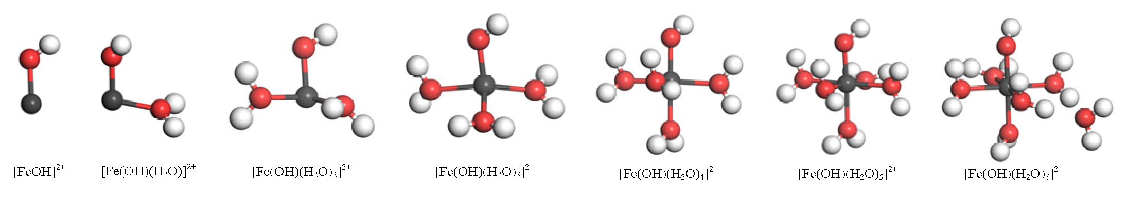
3.1. Hydration Structure and Properties of Fe(OH)2+

In the calculation, iron atoms are surrounded by a large number of water molecules, and only the first solvated shell of the adsorbate is considered. Figure 3 is the picture of equilibrium geometry of Fe(OH)(H2O)n2+ (n = 0–6). The iron atom forms coordination with the water molecules closest to it. As the number of H2O around the Fe atom continues to increase, the more regular the arrangement of these water molecules. When the coordination number of Fe atoms with surrounding water molecules exceeds 5, the coordination number does not increase, so the maximum coordination number of Fe hydroxy hydrate is 5.
Table 1 presents the calculated structural parameters and energy of Fe(OH)(H2O)n2+ (n = 1–6). Since each atom occupies a certain space in the molecule when the surrounding water molecules are constantly close to the iron atom, the atoms are too close to each other, and the two adjacent atoms will form overlapping electron clouds, resulting in repulsion, which will affect the coordination between water molecules and iron atoms. As can be seen from Table 1, with the increase of the number of water molecules coordinated with iron atoms, the mean distance (Rmean) between Fe and OW (O atom of water) gradually increases. The results are similar to that of the hydrate formation of other metal ions [42]. When the number of H2O is 1–3, with an increase in the hydration number, Fe obtains electrons from more H2O, the charge of Fe tends to decrease, and the ionicity decreases. When the number of H2O is 4–6, the charge of Fe does not continue to decrease and hardly changes; in addition, the ionicity remains basically unchanged. When the number of coordinating water molecules reaches six, the Ebind of hydrated Fe(OH)2+ reaches the lowest level, but the maximum length of Fe-Ow is significantly longer and reaches 3.567 Å. At the same time, one coordinating water molecule leaves its first solvation shell as shown in Figure 3. So hydrated Fe(OH)2+ can bind with five water molecules at most. The binding energy of Fe(OH)(H2O)52+ is the lowest, and the structure is relatively stable. Therefore, in the work that follows, Fe(OH)(H2O)52+ is chosen as the primary structure to perform the steps below.
In order to find out the charge change of Fe(OH)(H2O)52+, the Milliken charge population of Fe and O atoms is analyzed to explore the charge change of atoms [43]. The charge population of Fe(OH)(H2O)52+ is shown in Table 2. Fe mainly gains a large number of electrons (1.45) from the 3d orbital, a small number of electrons (0.22) from the 3s orbital, and lost a small number of electrons (0.07) from the 3p orbital. The total charge of Fe is reduced by 1.6; the O atom loses even more electrons from the 2p orbital, and the total charge is about −0.76~−0.94. Figure 4 is the picture of the differential charge density of Fe(OH)(H2O)52+. It can be seen from the figure that the H atoms donate electrons to the strongly electronegative O atoms, therefore, there is an electron-deficient area around the H atom, and an electron-gaining area around the O atom; the 3d orbital of the Fe atom gets some electrons from the O atom, and a small area of electron-gaining appears around it, but the Fe atoms as a whole are still in a state of loss of electrons and are positively charged, so there is also a small amount of electron-deficient area around the Fe atom, which is consistent with Table 2.

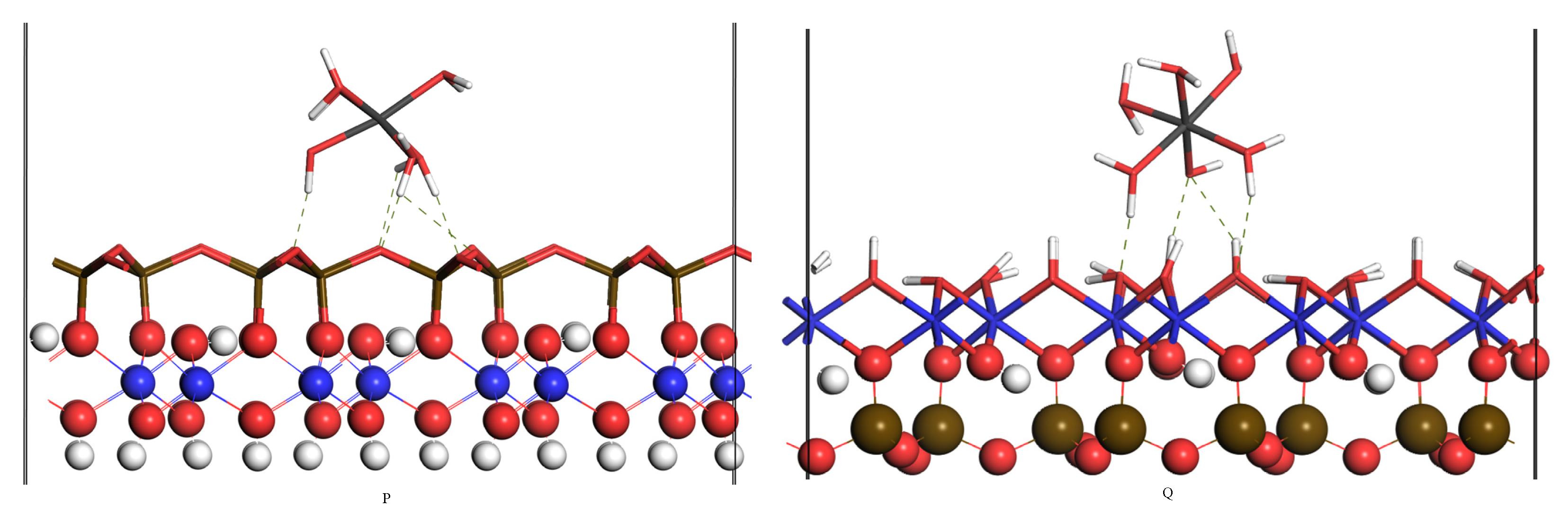
3.2. Outer Layer Adsorption Structure and Analysis

The outer layer adsorption of Fe(OH)(H2O)52+ on the Si-O and Al-OH surface was investigated and the compounds formed are named type P and type Q, respectively. As the adsorbate molecules are constantly approaching the surface of kaolinite, H-bonds will form hydrogen bonds between H and O atoms to generate intermolecular forces. The shorter the distance between H and O atoms, the stronger the H-bond formed. The system defaults to a maximum H-bond value of 2.58 Å, in the hydrogen bond formation range, the location of hydrogen bond formation is indicated by a dotted line in Figure 5. As shown in Figure 5, two kinds of H-bonds are presented. The kaolinite surface oxygen (Os) forms H-bonds with the hydrogen (Hw) of Fe(OH)(H2O)52+, and the oxygen (Ow) of Fe(OH)(H2O)52+ forms H-bonds with the hydrogen (Hs) of the surface, named “Os…Hw” and “Ow…Hs”, respectively [23]. When the hydrated Fe(OH)2+ outer layer is adsorbed on the Si-O surface, the length ranges of “Os…Hw” are 1.750–2.551 Å, and the “Ow…Hs” is not formed as presented in Table 3. When the hydrated Fe(OH)2+ outer layer adsorbed on the Al-OH surface, the length ranges of “Os…Hw” and “Ow…Hs” are 1.545–2.202 Å and 1.704–2.363 Å, respectively. The size of “Os…Hw” is shorter than the “Ow…Hs”, which indicated that the effect of “Os…Hw” is more desirable than that of “Ow…Hs”.
The adsorption energies and bond length are listed in Table 3. The coordination number of Fe(OH)(H2O)52+ showed no change after adsorption. The Fe-Ow average length and Fe-Ooh length in type P are slightly shorter than those in type Q. The adsorption energy of Fe(OH)(H2O)52+ on the Si-O and Al-OH surfaces was −1163.86 and −993.82 KJ/mol, respectively.
In general, when the hydrated Fe(OH)2+ outer layer adsorbed on the Si-O surface, the length of “Os…Hw” is slightly shorter, the number is more, and the length of “Fe-Ow” and “Fe-Ooh” is slightly shorter. The adsorption energy on the Si-O surface is lower than that on the Al-OH surface. Therefore, when hydrated Fe(OH)2+ adsorbed on the kaolinite (001) surface in the manner of outer layer adsorption, hydrated Fe(OH)2+ prefers adsorption on the Si-O surface. From the perspective of structure, compared with the Si-O surface, due to the presence of hydroxyl group on the Al-OH surface, the steric hindrance effect of adsorbent near the Al-OH surface becomes larger, which makes the adsorbent easier to adsorb on the Si-O surface. The outer layer adsorption of Al3+ on the kaolinite (001) surface also verified the effect [23].
To study the adsorption principle, the PDOS of Fe, Si-O surface, and Al-OH surface was analyzed. Figure 6a shows the PDOS of Fe and Si-O surfaces. As presented in Figure 6a, Fe moves towards the ground state as a whole in the PDOS after adsorption. The non-locality of the 3d orbital in the valence band and the 3p orbital in the conduction band is obviously increased, and the locality of the 3d orbital near the Fermi face is slightly enhanced. At the Fermi level, the domination of 3d orbital electrons of Fe decreases significantly, which indicated that the activity of Fe decreased and Fe became more stable after adsorption. In summary, Fe becomes more stable after adsorption. Similarly, after adsorption, the overall DOS of the Si-O surface moved towards to ground state, and the non-locality of the 2s and 2p orbitals was obviously improved, suggesting that the surface stability is good. The donation of the 2p at the Fermi face after adsorption descends greatly, and this indicates that surface activity diminishes.
Figure 6b is the PDOS of Fe and Al-OH surfaces. As illustrated in Figure 6b, after adsorption, the overall DOS of Fe shifted to the ground states, and the locality of Fe 3d orbital was slightly enhanced. The 2p orbital of Fe in the excited state is obviously shifted to the ground state, and the non-locality is rising. The contribution of Fe 3d orbital at the Fermi face was greatly decreased after adsorption. The 2p orbital of Fe also contributed slightly to the Fermi face, denoting that Fe activity decreased. The Al-OH surface changes in the same way that the Si-O surface changes.
Table 4 illustrates this. The Mulliken charge of Fe adsorbed on the Si-O surface demonstrates that the 3p of Fe loses 0.05 e and 3d of Fe receives 0.28 e. Fe receives a total of 0.27 e after adsorption. The Mulliken charge of Fe adsorbed on the Al-OH surface shows that the 3s of Fe loses 0.01 e, 3p receives 0.08 e and 3d receives 0.29 e. Fe receives a total of 0.37 e. The electrons acquired with the aid of Fe come from the O atoms of Fe(OH)(H2O)52+.
In general, the adsorption of hydrated Fe(OH)2+ on the Al-OH and Si-O surfaces significantly reduced the surface energy and made the surface more stable. The Fe in the hydrated Fe(OH)2+ gets some electrons, which reduces the ionicity of Fe. The activity of Fe atoms on the Fermi surface decreased, indicating that the adsorbate molecules also became more stable, indicating that the entire system after adsorption was also more stable. The comparison of the H-bonds and adsorption energies of adsorbate molecules on kaolinite (001) surfaces shows that the hydrated Fe(OH)2+ is more easily outer layer adsorbed on the Si-O surface. This is the same as the adsorption result of Al3+ on the kaolinite (001) surface [23].

3.3. Inner Layer Adsorption Structure and Analysis

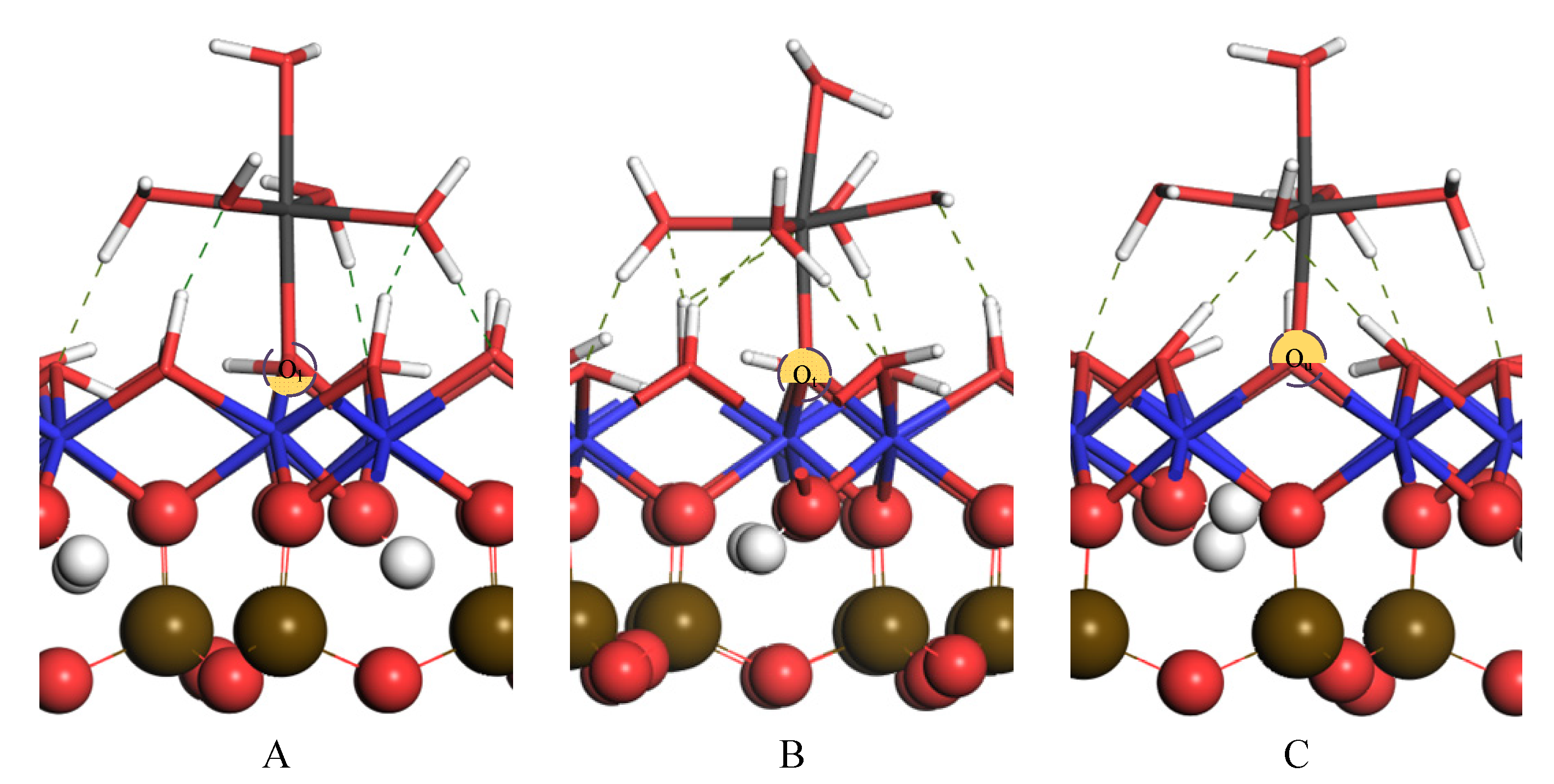
3.3.1. Monodentate Adsorption Structure

Figure 7 is the picture of Fe monodentate adsorbed on the Al-OH surface, Fe is bonded with Os atoms; There exists two basic types of H-bonds between hydrated Fe(OH)2+ and surface (dashed lines in Figure 7): “Os…Hw” and “Ow…Hs”, which is produced by the surface O of “Os” (including “Ou,” “Ot,” and “Ol”) with hydrogen (Hw) of the hydrated Fe(OH)2+, and the “Ow” of adsorbent with Hs of the surface. The maximum methane length is 2.58 by default. The H-bonds length of “Os…Hw” are 1.519–1.705 Å, 1.495–1.504 Å, and 1.467–1.618 Å, respectively, in the A-, B-, and C-type compounds (Table 5). It shows that the number of H-bonds is the same and that there is little difference in length in the three adsorption compounds. The H-bonds length of “Ow…Hs” is 1.473–1.862 Å, 1.698–2.448 Å, and 1.648–1.863 Å, respectively, in the A-, B-, and C-type compounds. The number of “Ow…Hs” is more in the B-type compound after comparison. In general, from the point of view of the H-bond, hydrated Fe(OH)2+ tends to slightly form a B-type compound.
The chemical bond formed between Fe and surface deprotonated Os atoms plays an important role in the stability of adsorption. The Fe-Os lengths in the A-, B-, and C-type compounds of hydrated Fe(OH)2+ are 2.021, 2.011, and 2.022 Å, respectively (Table 5). The Fe-Os length in compounds A, B, and C shows almost no difference. So, the effect of chemical bonds is almost the same.
As shown in Table 5, the energies formed by the three adsorption complexes are −1339.67 (A), −1384.67 (B), and −1423.83 KJ/mol (C), respectively. From the perspective of adsorption energy, when the C-type compound is formed, the adsorption energy is the lowest, indicating that the structure of the C-type compound is more stable.
Overall, both H-bonds and chemical bonds play important roles in the adsorption process. Among the three monodentate adsorption compounds, the difference in H-bonds is small, and the length of chemical bonds in A-, B-, and C- type compounds is almost the same. The type-C compound has a lower adsorption energy, so the formed configuration is more stable. Therefore, when the adsorbent is monodentate adsorbed occurs, it is easier to adsorb at the Ou site. Compared with the monodentate adsorption of hydrated Al3+ and hydrated Al(OH)2+ on the kaolinite surface, the adsorbent is more likely to be adsorbed on the upright hydroxyl O atom [23,44]. From the perspective of structure, it may be that the H atom on the upright hydroxyl group is more likely to be lost, leading to the stronger activity of the O atom and easier coordination bond with the adsorbent.

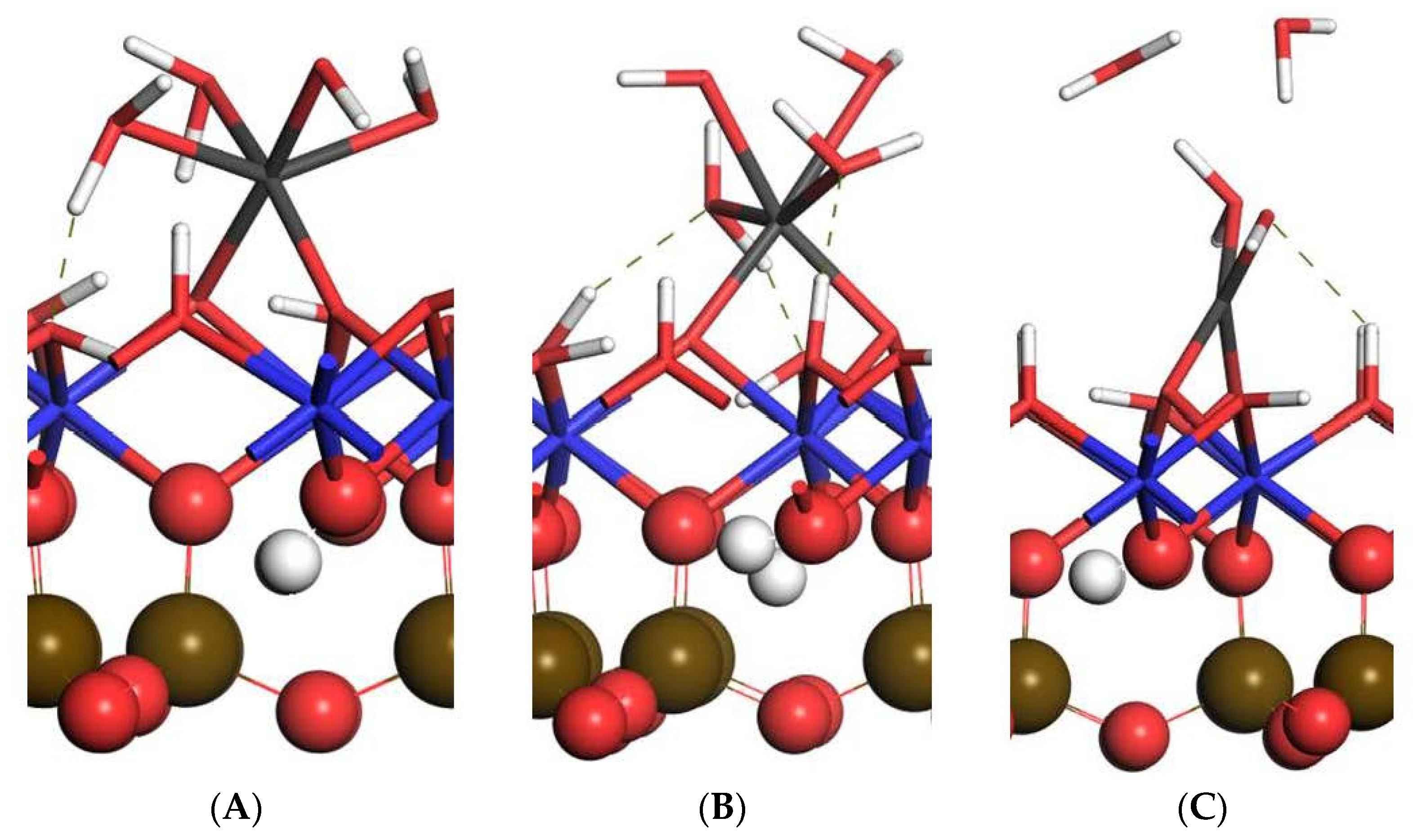
3.3.2. Bidentate Adsorption Structure

As proven in Figure 7, Fe can shape three bidentate adsorption compounds D, E, and F at “Ou-Ol”, “Ou-Ot” and “Ot-Ol” sites, respectively. In compound F, two water ligands disappear from the first solvation shell due to steric hindrance (Table 5). The H-bond of the bidentate adsorption compound is proven in Figure 8 by the dashed line. The simulation calculation sets the biggest H-bond size to 2.58 Å. “Os…Hw” lengths of D- and E-type compounds are 1.400 and 1.289 Å, respectively. There is no “Os…Hw” formed in the E-type compound. In the E-type compound, “Os…Hw” is relatively shorter. The lengths of “Ow…Hs” of the E-type compound range from 1.618 to 1.951 Å. The lengths of “Ow…Hs” of the F-type compound is 2.074 Å. The D-type compound show that no “Ow…Hs” is formed. In the E-type compound, the lengths of “Ow…Hs” is slightly shorter and the number is greater.
The lengths of “Fe- Os” there are at locations of “Ou-Ol”, ”Ou-Ot”, and “Ot-Ol” are, respectively, 1.851 to 2.032, 1.859 to 1.919, and 1.753 to 1.837. When compared to monodentate adsorption compounds, “Fe-Os” has a shorter length and a higher number. Comparing the three bidentate adsorption compounds D, E, and F, there is no obvious difference in “Fe-Os” bonds.
Type-D compounds have a slightly reduced energy than type-E and F compounds (Table 5). This indicates that type-D compounds are easier to form and that the compounds formed are more stable. The adsorbate is more easily adsorbed in the “Ou-Ol” position.
In general, even though the E-type compound has more H-bonds, its adsorption energy is higher. The chemical bond difference between the three bidentate adsorption compounds is not obvious, but the adsorption energy of compound D is the lowest. When the H-bond, chemical bond, and adsorption energy are all considered, it is possible to conclude that when the hydrated Fe(OH)2+ bidentate adsorbed on the kaolinite (001) Al-OH surface, it is more likely to be adsorbed at “Ou-Ol.”

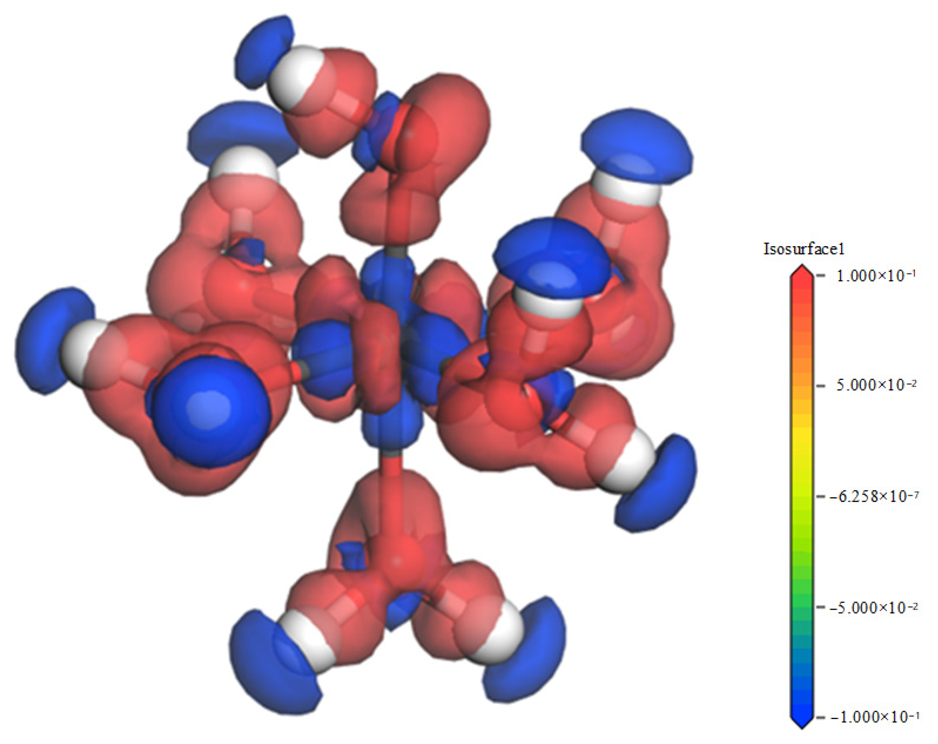
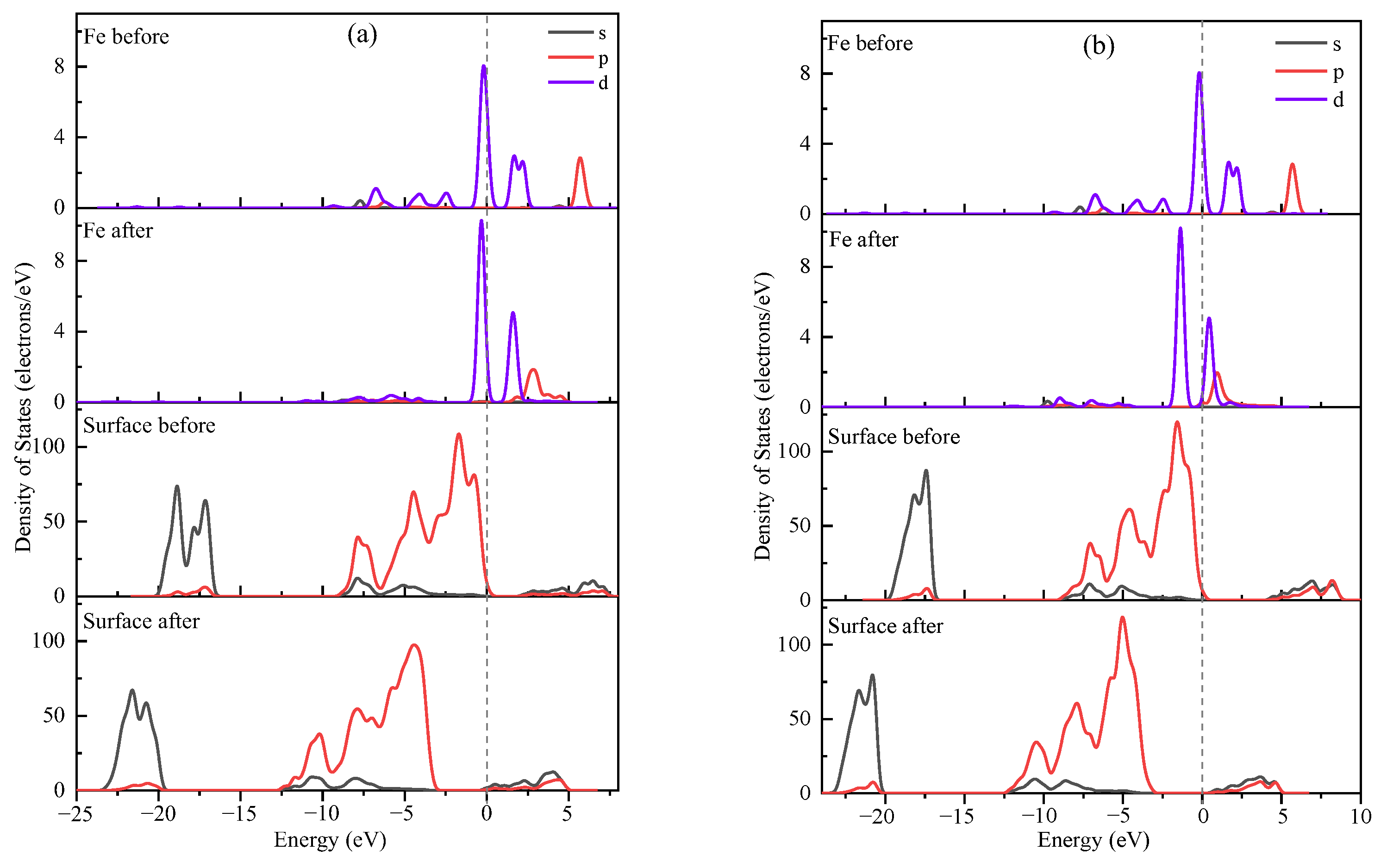
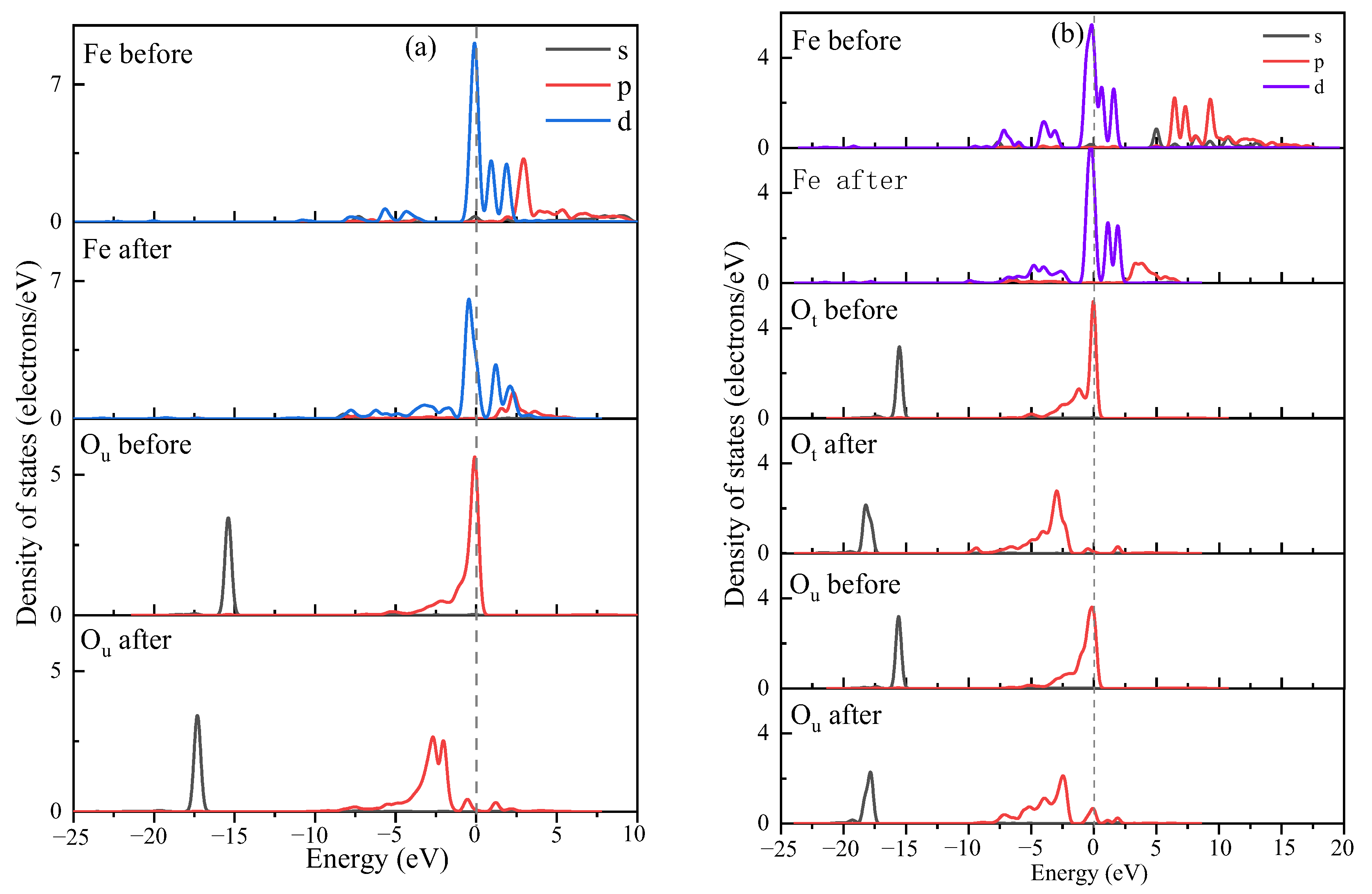
3.4. Explanation of Bonding Mechanisms

The monodentate adsorption compound C and the bidentate adsorption compound D were selected as the object of mechanism analysis. The Mulliken population and PDOS analysis is adopted to explain the bonding mechanism. As shown in Table 6, after adsorption, the 3s, 3p, and 3d orbitals of Fe obtained 0.04, 0.04, and 0.31 e, respectively. Fe obtained a total of 0.39 e after adsorption. The 2s orbital of the O atom bonded with Fe lost 0.06 e, the 2p orbital gained 0.29 e, and the O atom gained a total of 0.23 e after adsorption. Both Fe and surface O have gained some electrons, which came mainly from O and H atoms in hydrated Fe(OH)2+. Table 7 lists the charge transfers of O and H in hydrated Fe(OH)2+. As shown in Table 8, the total charges of O and H in water ligands and hydroxyl groups before adsorption are −4.36 and 4.95 e, respectively. The total charge of O and H after adsorption becomes −4.46 and 3.83 e, respectively. After adsorption, O loses 0.1 e and H loses 1.12 e, so it can be seen that the electrons obtained by surface O and Fe atoms mainly come from the O and H atoms in hydrated Fe(OH)2+. As shown in Table 8, after adsorption, the 3s and 3d orbitals of Fe obtained 0.05 e and 0.07 e, respectively, the 3p orbital lost 0.03 e, and Fe obtained a total of 0.09 e. The 2s orbitals of Ol and Ou bonded with Fe on the kaolinite surface both lose 0.04 e, the 2p acquire 0.18 e and 0.09 e, respectively, and the two oxygens gain 0.19 e. Similar to the monodentate adsorption, both Fe and surface O gained partial electrons, which also came mainly from O and H in the hydrated Fe(OH)2+. As shown in Table 8, after adsorption, O and H in hydrated Fe(OH)2+ lost 0.14 e and 1.02 e, respectively, and the lost electrons were partially transferred to Fe atoms and surface O atoms. The Mulliken overlapping layout values of Fe-Os in monodentate adsorption compounds were 0.32, and the Mulliken overlapping layout values of Fe-Os in bidentate adsorption compounds were 0.24 and 0.36. The overlapping layout values are all positive, so both Fe and surface O atoms are filled with bonding orbitals during inner layer adsorption processes. The bidentate adsorption process has one more chemical bond than the monodentate adsorption process, and the Fe-Os bond layout value formed in the bidentate adsorption process is slightly larger, and the stability is slightly better.
As shown in Figure 9a, after adsorption, the s and p orbitals of the iron atoms are closer to the Fermi level, and the d orbitals are closer to the excited state. The locality of the orbitals of iron atoms increases. The occupation of the Fe 3d orbital at the Fermi face increased slightly; the DOS of Ou atoms shifted to the ground state, indicating that Ou atoms obtained higher stability. The donation of the Ou atom’s 2p in the Fermi level decreases dramatically because the activity of the Ou atom decreases after adsorption, and impurity mountains in the scope of −3.5 to −2.3 eV appear, which is due to the bonding between surface O atoms and Fe atoms and the formation of bonding orbitals. Two impurity peaks appear in −0.5 to 2.5 eV. The cause of miscellaneous peaks is the bonding between surface O with Fe atoms and the formation of antibonding orbitals. In the range of −7.5 to −3.5 eV and −19 to −18 eV, Fe atoms and surface O are filled with bonding orbitals. In general, the bonding between Fe and O atoms on the surface is greater than the antibonding, and the bonding orbital is formed as a whole, which indicates that the adsorbent is relatively stable during the adsorption on the surface.
As shown in Figure 9b, after adsorption, the 3s and 3p orbitals of Fe are caged toward the Fermi face. The 3d of Fe moves slightly to the excited state, the locality of the 3d of Fe at the Fermi face is marginally enhanced, and the non-locality of the 3d orbital at the ground state is obviously enhanced; the DOS of Ol and Ou shifted to the ground state, indicating that the adsorbed Ol and Ou atoms became more stable. The non-locality of Ol and Ou’s s and p orbitals is greatly boosted, while the donation of the 2p in the Fermi level is clearly lower, implying that the activity of the surface Ol atoms after adsorption is greatly decreased; after adsorption, Ol atoms appear in three consecutive impurity peaks in the range of −1.0 to 2.5 eV, which is caused by the formation of antibonding orbitals between Ol and Fe, but in the large range of −20 to −1.5 eV, the surface Ol and Fe are filled with bonding orbitals. As a result, bonding state filling dominates the electronic interaction between Fe and surface Ol. Two impurity peaks appear in the range of −1.0 to −0.5 eV and 1.5 to 2.5 eV for the Ou atom, which is due to Ou bonding with Fe and filling with antibonding orbitals. However, in the ground state, the electron interactions between Fe atoms and surface Ou atoms are mainly filled with bonding states. Therefore, Fe and surface oxygen atoms eventually form bonding orbitals.

4. Conclusions

DFT research methods are widely used to study the relationship between molecules and mineral surfaces, and in the field of mineral processing, DFT can be used to study the relationship between pharmaceutical molecules and mineral surfaces and the occurrence state of ions on clay mineral surfaces, etc., which has great development prospects. In this paper, the optimal hydrate structure of Fe(OH)2+ in the water environment was built using DFT. On the surface of kaolinite (001), the compound of outer layer and inner layer (monodentate/bidentate) adsorption of hydrate Fe(OH)2+ were investigated for structure and bonding mechanisms. The study’s findings are as follows:
(1)
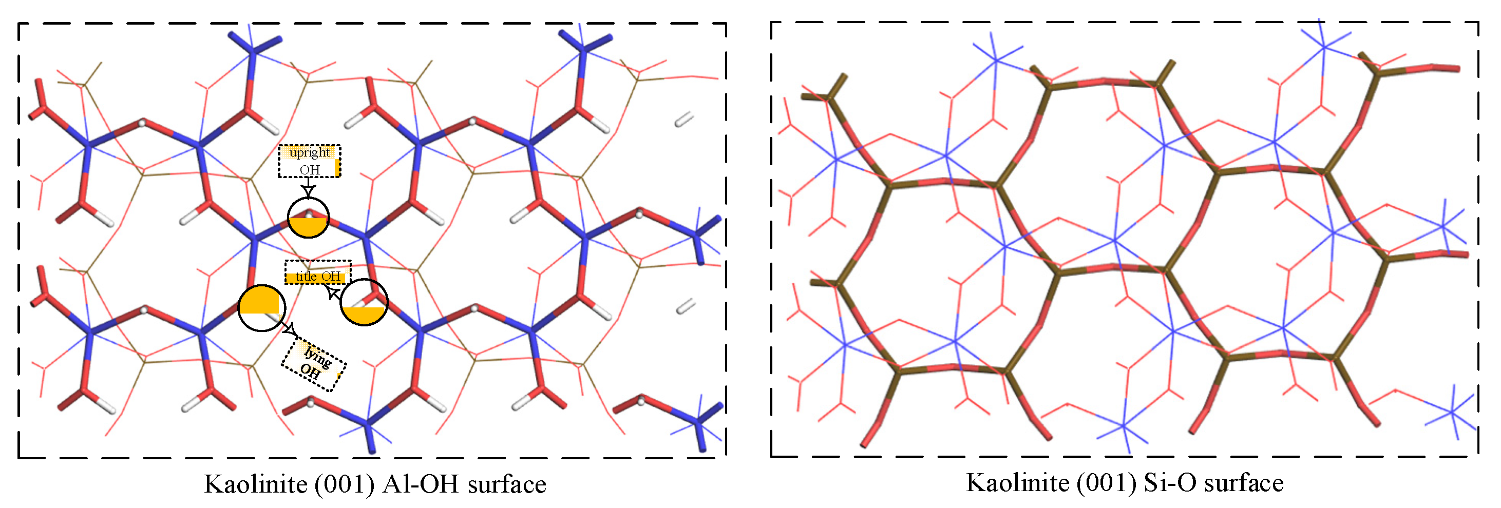
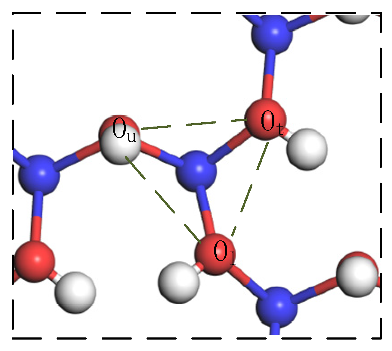
The stable structure of hydrated Fe(OH)2+ is [Fe(OH)(H2O)5]2+. The adsorbent has a tendency to outer layer adsorb on the kaolinite Si-O surface. If inner layer adsorption occurs on the surface, monodentate adsorption is performed at the upright hydroxyl O and bidentate adsorption is performed between the upright and lying hydroxyl O. Bidentate adsorption has a lower adsorption energy than monodentate adsorption, indicating that adsorbent is more likely to adsorb on the Al-OH surface in the bidentate adsorption manner.
(2)
The bonding mechanism and PDOS evaluation confirmed that when outer layer adsorption occurs, the interplay between the adsorbate molecules and the kaolinite molecules was once typically via H-bonding. When outer layer adsorption occurs, the interplay between adsorbate molecules and kaolinite molecules is in the main through vulnerable H-bonds and sturdy chemical bonds, the ionicity of Fe-Os bonds is reduced, and the covalency is enhanced. Compared with monodentate adsorption, bidentate adsorption has lower adsorption energy and greater covalent bonds, so the hydrated Fe(OH)2+ is greater without problems with bidentate adsorbed.

Author Contributions

H.W. (Hongqiang Wu): Conceptualization, Formal Analysis, Writing—Original Draft. Y.M.: Visualization, Resources, Methodology, Software. J.T.: Resources. H.Y.: Conceptualization, Funding Acquisition, Resources, Supervision, Writing—Review and Editing. Y.L.: Supervision. S.Q.: Software, Validation. H.W. (Hao Wu): Investigation. T.Q.: Review and Editing. All authors have read and agreed to the published version of the manuscript.

Funding

National Natural Science Foundation of China (No. 52274262 and 52004107), Natural Science Foundation of Jiangxi Province (No. 20224BAB204036), General Projects of Key RD Programs of Jiangxi Province (20212BBG73049), China Engineering Science and Technology Development Strategy Jiangxi Research Institute Consulting Research Project (2022-02JXZD-02), Cultivation Project of the State Key Laboratory of Green Development and High Value Utilization of Ionic Rare Earth Resources in Jiangxi Province (20194AFD44003), National innovation and entrepreneurship Training Program for college students (202110407032).

Data Availability Statement

Not applicable.

Acknowledgments

The authors gratefully acknowledge the support from the National Natural Science Foundation of China (No. 52274262 and 52004107), Natural Science Foundation of Jiangxi Province (No. 20224BAB204036), General Projects of Key RD Programs of Jiangxi Province (20212BBG73049), China Engineering Science and Technology Development Strategy Jiangxi Research Institute Consulting Research Project (2022-02JXZD-02), Cultivation Project of the State Key Laboratory of Green Development and High Value Utilization of Ionic Rare Earth Resources in Jiangxi Province (20194AFD44003), National innovation and entrepreneurship Training Program for college students (202110407032).

Conflicts of Interest

The authors declare no conflict of interest.

References

  1. Huang, C.M.; Wang, C.S. Geochemical features of rare earth elements in process of rock weathering and soil formation. Chin. Rare Earths 2022, 23, 46–49. [Google Scholar]
  2. Luo, X.P.; Wen, C.J.; Xu, J.; Ma, P.L.; Tang, X.K.; Chi, R.A. Research prowess on and development trend of exploitation technique of ion-absorbed type rare earth ore. Met. Mine 2014, 6, 83–90. [Google Scholar]
  3. Zhang, H.L.; Xu, Z.J.; Sun, W.; Chen, D.X.; Li, S.; Han, M.J.; Yu, H.; Zhang, C.Y. Selective adsorption mechanism of dodecylamine on the hydrated surface of hematite and quartz. Sep. Purif. Technol. 2021, 275, 119137. [Google Scholar] [CrossRef]
  4. Wang, X.T.; Chen, Y.R.; Mi, J.Q.; Jiang, J.W.; Jiang, J. Research status of leaching technology and leaching agent of ion-adsorption type rare earth ore. World Nonferrous Met. 2021, 22, 136–139. [Google Scholar]
  5. Luo, X.P.; Qiu, T.S.; Yan, Q.; Fang, X.H. Research progress and developing orientation of chemical extraction technology of weathing crust strain amass-type rare earth ore. J. Jiangxi Univ. Sci. Technol. 2002, 23, 1–6. [Google Scholar]
  6. Ouyang, K.S.; Rao, G.H.; Yao, H.Q.; Mao, Y.H. Study of southern RE ore leaching by aluminum inhibition. Rare Met. Cem. Carbides 2003, 31, 1–3. [Google Scholar]
  7. Qiu, T.S.; Zhu, D.M.; Fang, X.H.; Zeng, Q.H.; Gao, G.K.; Zhu, H.L. Leaching kinetics of ionic rare-earth in ammonia-nitrogen wastewater system added with impurity inhibitors. J. Rare Earths 2014, 32, 1175–1183. [Google Scholar] [CrossRef]
  8. Qiu, T.S.; Fang, X.H.; Wu, H.Q.; Zeng, Q.H.; Zhu, D.M. Leaching behaviors of iron and aluminum elements of ion-absorbed-rare-earth ore with a new impurity depressant. Trans. Nonferrous Met. Soc. China 2014, 24, 2986–2990. [Google Scholar] [CrossRef]
  9. Fang, X.H.; Xia, Y.Y.; Qiu, T.S.; Zhu, D.M. Influence of tartaric acid on impurity leaching behavior of ionic rare earth ores. Met. Mine 2018, 6, 94–98. [Google Scholar]
  10. Fang, X.H.; Zhu, D.M.; Qiu, T.S.; Wu, H.Q. Impurities inhibited leacning of the leach liquor of the weathered crust elution-deposited rare earth ore by adding aluminum inhibitor. Nonferrous Met. Sci. Eng. 2012, 3, 51–55. [Google Scholar] [CrossRef]
  11. Wu, X.Y.; Zhou, F.; Xu, Y.L.; Feng, J.; Chi, R.A. Research progress on the rare earth leaching agents of weathered crust elution-deposited rare earth ore. Chin. Rare Earths 2021, 42, 109–118. [Google Scholar]
  12. Zhao, Z.H.; Sang, X.Y.; Zhang, W.B.; Hao, G.H.; Duan, C.K.; Li, D. Application of centrifuging sedimentation on removing aluminum and iron from rare earth solution. Chin. Rare Earths 2007, 28, 95–97. [Google Scholar]
  13. Xu, Y.H. Removing of aluminum from praseodymium-neodymium carbonate. Hydrometall. China 2005, 24, 92–94. [Google Scholar]
  14. Yin, J.Q.; Fu, G.M.; Wan, Y.; Tian, J. Development progress of extraction rare earths from the leach liquid of the weathered crust elution-deposited rare earth ore. Jiangxi Sci. 2012, 30, 574–578. [Google Scholar]
  15. Niyaz, M.M.; Mokhtar, A. Modeling and sensitivity analysis of dyes adsorption onto natural adsorbent from colored textile wastewater. J. Appl. Polym. Sci. 2008, 109, 4043–4048. [Google Scholar]
  16. Niyaz, M.M.; Mokhtar, A. Numerical finite volume modeling of dye decolorization using immobilized titania nanophotocatalysis. Chem. Eng. J. 2009, 146, 189–193. [Google Scholar]
  17. Fang, F.; Min, F.; Liu, L.; Chen, J.; Ren, B.; Liu, C. Adsorption of Al(OH)n(3-n)+ (n =2–4) on kaolinite (001) surfaces: A DFT study. Appl. Clay Sci. 2020, 187, 105455. [Google Scholar] [CrossRef]
  18. Wang, J.; Xia, S.W.; Yu, L.M. Adsorption mechanism of hydrated Pb(OH)+ on the kaolinite (001) surface. Acta Phys. Chim. Sin. 2014, 5, 829–835. [Google Scholar]
  19. Peng, C.; Min, F.; Liu, L.; Chen, J. The adsorption of CaOH+ on (001) basal and (010) edge surface of Na-montmorillonite: A DFT study: DFT study of adsorption of CaOH+ on (001) Na-montmorillonite surface. Surf. Interface Anal. 2017, 49, 267–277. [Google Scholar] [CrossRef]
  20. Zhang, Z.J.; Zhou, Q.; Yuan, Z.T.; Zhao, L.; Dong, J.D. Adsorption of Mg2+ and K+ on the kaolinite (0 0 1) surface in aqueous system: A combined DFT and AIMD study with an experimental verification. Appl. Surf. Sci. 2021, 538, 148158. [Google Scholar] [CrossRef]
  21. Qiu, T.S.; Qiu, S.; Wu, H.; Yan, H.S.; Li, X.B.; Zhou, X.W. Adsorption of hydrated [Y(OH)2]+ on kaolinite (001) surface: Insight from DFT simulation. Powder Technol. 2021, 387, 80–87. [Google Scholar] [CrossRef]
  22. Qiu, S.; Wu, H.; Yan, H.S.; Li, X.B.; Zhou, X.W.; Qiu, T.S. Theoretical investigation of hydrated [Lu(OH)2]+ adsorption on kaolinite (001) surface with DFT calculations. Appl. Surf. Sci. 2021, 565, 150473. [Google Scholar] [CrossRef]
  23. Miao, Y.Q.; Yan, H.S.; Qiu, X.H.; Zhou, X.W.; Zhu, D.M.; Li, X.B.; Qiu, T.S. Adsorption of hydrated Al3+ on the kaolinite (001) surface: A density functional theory study. Appl. Clay Sci. 2022, 225, 106498. [Google Scholar] [CrossRef]
  24. Yan, H.S. First-Principles Study on the Adsorption of Hydrated Rare Earth Ions on the Surface of Kaolinite; Jiangxi University of Science and Technology: Ganzhou, China, 2019. [Google Scholar]
  25. Liu, X.D.; Jan Meijer, E.; Lu, X.C.; Wang, R.C. First-principles molecular dynamics insight into Fe2+ compounds adsorbed on edge surface of clay minerals. Clays Clay Miner. 2012, 60, 341–347. [Google Scholar] [CrossRef]
  26. Feng, X.; Onel, O.; Council-Troche, M.; MacCormac, B.L.; Noble, A.; Yoon, R.H.; Morris, J.R. Rare earth ion-adsorption clays in the presence of iron at basic pH: Adsorption mechanism and extraction method. Appl. Clay Sci. 2023, 231, 106744. [Google Scholar] [CrossRef]
  27. Hohenberg, P.; Kohn, W. Inhomogeneous electron gas. Phys. Rev. J. 1964, 136, B864–B871. [Google Scholar] [CrossRef] [Green Version]
  28. Kohn, W.; Sham, L.J. Self-consistent equations including exchange and correlation effects. Phys. Rev. J. 1965, 140, A1133–A1138. [Google Scholar] [CrossRef] [Green Version]
  29. Clark, S.J.; Segall, M.D.; Pickard, C.J.; Hasnip, P.J.; Probert, M.J.; Refson, K.; Payne, M.C. First principles methods using CASTEP. Z. Fur Krist. Cryst. Mater. 2005, 220, 567–570. [Google Scholar] [CrossRef] [Green Version]
  30. Wu, Z.; Cohen, R.E. More accurate generalized gradient approximation for solids. Phys. Rev. B 2006, 73, e235116. [Google Scholar] [CrossRef] [Green Version]
  31. Ireta, J.; Neugebauer, J.; Scheffler, M. On the accuracy of DFT for describing H-bonds: Dependence on the bond directionality. J. Phys. Chem. A 2004, 108, 5692–5698. [Google Scholar] [CrossRef] [Green Version]
  32. Vanderbilt, D. Soft self-consistent pseudopotentials in a generalized eigenvalue formalism. Phys. Rev. B 1990, 41, 7892–7895. [Google Scholar] [CrossRef] [PubMed]
  33. Monkhorst, H.J.; Pack, J.D. Special points for brillouin-zone integrations. Phys. Rev. B 1976, 13, 5188–5192. [Google Scholar] [CrossRef]
  34. Pack, J.D.; Monkkorst, H.J. Special points for brilliouin-zone zategrations—A reply. Phys. Rev. B 1976, 16, 1748–1749. [Google Scholar] [CrossRef]
  35. Yin, Z.G.; Hu, Y.H.; Sun, W.; Zhang, C.Y.; He, J.Y.; Xu, Z.J.; Zou, J.X.; Guan, C.P.; Zhang, C.H.; Guan, Q.J.; et al. Adsorption mechanism of 4-amino-5-mercapto-1,2,4-triazole as flotation reagent on chalcopyrite. Langmuir 2018, 34, 4071–4083. [Google Scholar] [CrossRef]
  36. He, J.Y.; Zhang, H.L.; Yue, T.; Sun, W.; Hu, Y.H.; Zhang, C.Y. Effects of hydration on the adsorption of benzohydroxamic acid on the lead-ion-activated cassiterite surface: A DFT study. Langmuir 2021, 37, 2205–2212. [Google Scholar] [CrossRef]
  37. Zhang, C.; Zhang, Q.J.; Huang, B. Contamination prevention control for ion-adsorbed rare earth deposit mining. Energy Sav. Non Ferr. Metall. 2021, 37, 46–49. [Google Scholar]
  38. Zhang, H.L.; Sun, W.; Zhu, Y.G.; He, J.Y.; Chen, D.X.; Zhang, C.Y. Effects of the goethite surface hydration microstructure on the adsorption of the collectors dodecylamine and sodium oleate. Langmuir 2021, 37, 10052–10060. [Google Scholar] [CrossRef]
  39. He, J.Y.; Wang, L.; Zhang, C.Y.; Sun, W.; Yin, Z.G.; Zhang, H.L.; Chen, D.X.; Pei, Y. A high throughput screening model of solidophilic flotation reagents for chalcopyrite based on quantum chemistry calculations and machine learning. Miner. Eng. 2022, 177, 107375. [Google Scholar] [CrossRef]
  40. Chen, J.H. The interaction of flotation reagents with metal ions in mineral surfaces: A perspective from coordination chemistry. Miner. Eng. 2021, 171, 107067. [Google Scholar] [CrossRef]
  41. Luo, A.R.; Chen, J.H. Effect of hydration and hydroxylation on the adsorption of metal ions on quartz surfaces: DFT study. Appl. Surf. Sci. 2022, 595, 153553. [Google Scholar] [CrossRef]
  42. Wang, X.Y.; Liu, W.G.; Duan, H.; Wang, B.Y.; Han, C.; Wei, D.Z. The adsorption mechanism of calcium ion on quartz (101) surface: A DFT study. Power Technol. 2018, 329, 158–166. [Google Scholar] [CrossRef]
  43. Mulliken, R.S. Electronic population analysis on LCAO–MO molecular wave functions. J. Chem. Phys. 1955, 23, 1833–1840. [Google Scholar] [CrossRef] [Green Version]
  44. Miao, Y.Q.; Yan, H.S.; Hong, B.G.; Zhou, X.W.; Tong, L.C.; Xiao, Y.F.; Qiu, T.S. DFT study of the effect of impurity defects on the inner-layer adsorption of hydrated Al(OH)2+ on the kaolinite (0 0 1) surface. J. Mol. Liq. 2022, 368, 120819. [Google Scholar] [CrossRef]
Figure 1. Kaolinite (001) surface model.
Processes 11 00038 g001
Figure 2. Picture of the sites of hydrate Fe(OH)2+ inner-layer adsorption on Al-OH surface.
Processes 11 00038 g002
Figure 3. Picture of equilibrium geometry of Fe(OH)(H2O)n2+ (n = 0–6).
Processes 11 00038 g003
Figure 4. Picture of differential charge density of Fe(OH)(H2O)52+ (isodensity is ±0.100 electrons/Å3).
Processes 11 00038 g004
Figure 5. The outer layer adsorption structures of hydrated Fe(OH)2+ on Si-O surface (P) and Al-OH surface (Q), respectively.
Processes 11 00038 g005
Figure 6. The PDOS of outer layer adsorption of Fe with Si-O surface (a) and Al-OH surface (b).
Processes 11 00038 g006
Figure 7. Picture of monodentate adsorption structures of Fe at “Ol” (A), “Ot” (B), and “Ou” (C) the positions on Al-OH surface.
Processes 11 00038 g007
Figure 8. The bidentate adsorption structures of hydrated Fe(OH)2+ at positions “Ou-Ol” (A), “Ou-Ot” (B), and “Ot-Ol” (C), respectively.
Processes 11 00038 g008
Figure 9. Fe and Ou PDOS in forms C (a) and Fe, Ol, and Ou PDOS in forms D (b). Fermi face is the line at 0 eV.
Processes 11 00038 g009
Table 1. Calculated structural parameters and energy of Fe(OH)(H2O)n2+ (n = 1–6).
nR (Fe-Ooh)/Å aR (Fe-Ow)minR (Fe-Ow)max bR (Fe-Ow)mean cQFe dEbind
11.6931.8471.8471.8471.62−338.79
21.7201.8781.8811.8801.52−924.35
31.7251.8631.8961.8841.39−3043.14
41.7611.9011.9691.9291.40−2996.45
51.7721.9401.9721.9571.40−3215.26
61.7771.9403.5672.2231.39−3321.96
a The distance between Fe and O of hydroxyl groups. b The longest distance between Fe and O of aqua ligands. c The mean distance between Fe and O of aqua ligands. d The charge of Fe.
Table 2. Milliken charge population of Fe(OH)(H2O)52+.
AtomspdTotalCharge/e
O1.904.8606.76−0.76
O1.865.0306.89−0.89
O1.855.0606.91−0.91
O1.855.0906.94−0.94
O1.865.0406.90−0.90
O1.855.0606.91−0.91
Fe0.22−0.076.456.601.40
Table 3. Bond length (Å) and adsorption energies (KJ/mol) of Fe(OH)(H2O)52+.
FormM a(Fe-Ooh) b(Fe-Ow)mean cOs-HwOw-HsEads
P51.9431.9891.750, 1.780, 1.802
2.150, 2.438, 2.541
2.551
/−1163.86
Q51.9461.9931.545, 2.2021.704, 2.363−993.82
a The number of water molecules around Fe. b Distance between Fe and O of hydroxyl. c Mean length between Fe and O of water ligand.
Table 4. Mulliken charge of Fe, respectively, on Si-O and Al-OH surface.
SurfaceStatespdTotalCharge/e
Si-OFe before0.22−0.076.456.601.40
Fe after0.22−0.126.736.871.13
Al-OHFe before0.22−0.076.456.601.40
Fe after0.210.016.746.971.03
Table 5. Bonds length (Å) and energies (KJ/mol) of the compounds.
FormM aFe-Os bFe-Ooh cFe-Ow dOs-HwOw-HsEads
P5\1.9431.960, 1.965, 2.002
2.006, 2.013
1.750, 1.780, 1.802
2.150, 2.438, 2.541
2.551
/−1163.86
Q5\1.9461.973, 1.980, 1.994
2.008, 2.008
1.545, 2.2021.704, 2.363−993.82
A42.0211.9522.005, 2.008
2.024, 2.044
1.519, 1.531, 1.7051.473, 1.862−1339.67
B42.0111.9841.968, 1.979
2.017, 2.030
1.495, 1.502, 1.5041.698, 1.803
1.812, 2.448
−1384.67
C42.0221.9661.997, 2.025
2.027, 2.030
1.467, 1.550, 1.6181.648, 1.863−1423.83
D31.851
2.032
1.9451.949, 1.994, 2.0121.400\−1713.89
E31.859
1.919
2.0581.922, 2.046, 2.2331.2891.618, 1.951−1598.90
F11.753
1.837
1.8041.936\2.074−1664.17
a Lig and number. b Length of Fe to surface oxygen. c Length of Fe to O of -OH. d Length of Fe to O of H2O.
Table 6. Mulliken charge populations of monodentate adsorption, and Mulliken overlap populations of Fe-Os bonds.
StatesFeOsFe-Os
spdTotalCharge/espTotalCharge/e
Before0.20−0.046.446.601.401.914.906.81−0.81/
After0.24−0.006.756.991.011.855.197.04−1.040.32
Charge0.040.040.310.39−0.39−0.060.290.23−0.23/
Table 7. Charge transfers (e) of O and H in hydrated Fe(OH)2+ in compounds C and D.
FormQoQHQo′QHQo aΔQH
C−4.364.95−4.463.83−0.10−1.12
D−3.343.95−3.482.93−0.14−1.02
a The charge transfer value is estimated using the formula Δ Q = Q Q , Q , and Q is the total charge of O and H atoms in hydrated Fe(OH)2+ after and before adsorption, respectively.
Table 8. Mulliken charge populations of bidentate adsorption, and Mulliken overlap populations of Fe-Os bonds.
StatesFeOlOuFe-Os
spdTotalCharge/espTotalCharge/espTotalCharge/e
Before0.18−0.016.446.611.391.914.956.86−0.861.904.986.88−0.880.24
0.36
After0.23−0.046.516.701.301.875.137.00−1.001.865.076.93−0.93
Charge0.05−0.030.070.09−0.09−0.040.180.14−0.14−0.040.090.05−0.05
Disclaimer/Publisher’s Note: The statements, opinions and data contained in all publications are solely those of the individual author(s) and contributor(s) and not of MDPI and/or the editor(s). MDPI and/or the editor(s) disclaim responsibility for any injury to people or property resulting from any ideas, methods, instructions or products referred to in the content.

