Article

Design Optimization and Experimental Verification of Spiral Cone Centrifugal Fertilizer Apparatus Based on the Discrete Element Method

1
Henan Province Engineering Research Center of Ultrasonic Technology Application, Pingdingshan University, Pingdingshan 467000, China
2
Key Laboratory of Agricultural Equipment in Mid-Lower Yangtze River, Ministry of Agriculture and Rural Affairs, Wuhan 430070, China
*
Author to whom correspondence should be addressed.
Processes 2023, 11(1), 199; https://doi.org/10.3390/pr11010199
Submission received: 29 November 2022 / Revised: 2 January 2023 / Accepted: 4 January 2023 / Published: 7 January 2023

Abstract

:
This study attempts to optimize the arc-shaped coned disk affecting the uniformity of the earlier designed fertilizer apparatus (FA), in particular, for application in the rice–oil rotation region in the middle and lower reaches of the Yangtze River, China. Based on theoretical analysis, a circular coned disk with the curvature gradual decline (GD) from top to bottom was designed, and the equation of the circular cone was determined. The EDEM discrete element software was used, using the coefficient of variation of the fertilization amount consistency in every row, the coefficient of variation of the fertilization amount stability, and the coefficient of variation of the fertilization amount consistency in the same row as evaluation indices. Simulations and comparative tests of FA performance were performed for three cases of the busbar top-to-bottom curvature variation: (i) gradual increase (GI), (ii) gradual decline (GD), and (iii) zero (0) variation. The experimental results show that at the FA rotation speed of 100~120 r/min and tilt of 1°~5°, the optimized FA had the optimal performance. High tilts and low rotation speeds provided the worst performance, with the variation coefficient of inter-row fertilization amount consistency of the FA below 10.23%. The variation coefficient of fertilizing amount stability was lower than 6.74%. The variation coefficient of intra-row fertilizing amount consistency was lower than 3.52%, while all performance indicators met the quality requirements of fertilizer discharge. Bench tests of the FA revealed that the variation coefficient of inter-row fertilizing amount consistency of the FA was below 10.23%, the variation coefficient of fertilizing amount stability was below 6.74%, and the variation coefficient of intra-row fertilizing amount consistency was below 3.52%. Field tests of the FA revealed that the variation coefficient of inter-row fertilizing amount consistency was below 7.68%, the variation coefficient of fertilizing amount stability was below 4.95%, and the variation coefficient of intra-row fertilizing amount stability was below 3.57%. All parameters were better than the industry standard, demonstrating that the FA had good fertilizing performance and met the quality requirements of field fertilization operations.

1. Introduction

Agricultural non-point source pollution is an important factor restricting the sustainable development of agriculture and rural economies [1,2,3,4]. Precision fertilization is one of the key technologies to achieve agricultural non-point source pollution control. It is also an essential guarantee for the promotion and application of chemical fertilizer reduction and efficiency enhancement technologies, as well as agriculture’s green and sustainable development [5,6,7]. A uniform fertilizer plate is a core working component in the precision fertilization process to improve the fertilization uniformity and stability of the spiral cone centrifugal fertilizer apparatus (FA). It is also a vital factor influencing the precision of fertilizer application.
There are few studies on uniform fertilizer plates worldwide, and most studies focus on centrifugal FAs [8,9,10,11,12]. Jia et al. [13] designed a parabolic surface screed plate to improve the uniformity of humidification during the conditioning process of brown rice and carried out multifactor experiments using simulation software to obtain the optimized parameter combination of the screed plate. The research on cone-shaped seed-metering devices that could realize component seeding started as early as the 1950s [14]. Yang et al. [15] determined the critical parameters affecting the performance of the tapered canvas-belt seed-metering device through theoretical analysis and determined the optimized parameters of the FA through a three-factor quadratic rotation test, and a field test verified the seeding performance. Xu et al. [16] determined the key parameters affecting the uniformity of the seeding device through the mechanical analysis of the seeding cone of the seed meter and defined the parameters of the seeding cone through theoretical analysis. Yang et al. [17] performed a theoretical analysis of the seeding process in the cone centrifugal seed-metering device in the breeding drilling machine and analyzed the flow state of seeds in the seed-metering device and the force and motion of seeds in the cone seeding and centrifugal distribution device. Then, the existing centrifugal seed-metering device was optimized and improved.
Centrifugal FAs are widely used in field operations worldwide [18,19,20,21], and their crucial indicator is the uniformity of fertilizer spread. Sun et al. [22] optimized the core components of a centrifugal fertilizer distributor to improve fertilization uniformity and stability. Yang et al. [23] selected three key parameters controlling the uniformity of the centrifugal disc fertilizer distributor and carried out a response surface analysis test and a single factor test, as well as an experimental optimization of the FA. Hu et al. [24] designed an offset centrifugal fertilizer’s spreading disc with adjustable blade position and inclination according to the row spacing of tea trees and the physical characteristics of fertilizers. Guo et al. [25] designed a turntable variable FA and determined the parameters of critical components through theoretical analysis. Liu et al. [26] applied EDEM simulation software commonly used by scholars [27,28] at home and abroad to carry out single-factor experiments, multiple regression orthogonal rotation experiments, and objective optimization experiments on the factors affecting the uniformity of fertilization. It can be seen from the above research that uniformity is still a vital issue studied by scholars worldwide, and it is of great significance to saving planting and fertilizer and improving the precision of fertilization.
This study attempted to optimize the arc-shaped coned disk (ASCD) in the earlier designed spiral cone centrifugal FA [29,30] by the fertilizing performance criterion to further improve the fertilization apparatus’s uniformity and overall performance, and we analyzed the movement of granular fertilizer on the ASCD. In addition, we carried out simulation experiments of different forms of FA and explored their internal mechanisms to improve the overall performance of the FA with the following experimental verification.

2. Materials and Methods

2.1. Overall FA Structure and Working Principles

The spiral cone centrifugal FA contains the upper and lower shells and spiral disturbance coned disk, among other components. The latter comprises a spiral disturbance cup and an arc-shaped coned disk (ASCD). Its structure is shown in Figure 1.
When the FA is operating, under the rotation of the SDCD, the granular fertilizer is evenly dispersed to the circumference of the coned disk through the coned disk surface through the coil disturbance action of the spiral disturbance cup and the cone top action of the ASCD. Furthermore, it will be filled with the fertilizer chamber and discharged from the fertilizer discharge port to complete the precise and stable fertilizer discharge operation.

2.2. Analysis and Optimization of Fertilizer Uniform Plate

The ASCD is the main structure that affects the movement of granular fertilizer in the FA. Its busbar is a critical parameter that affects the rapid and uniform movement of the granular fertilizer to its surroundings on the ASCD surface. The movement of granular fertilizer on the fertilizer uniform plate mainly includes the movement on the surface of the fertilizer uniform plate and the disturbance area. The rapid downward movement of the granular fertilizer through the ASCD surface is a critical factor in improving the fertilization uniformity and stability of the FA.
The interaction forces between granular fertilizers are ignored to analyze the regularity of granular fertilizer moving outside the FA at different positions on the ASCD surface. The granular fertilizer located anywhere on the ASCD surface is selected as the target, and its force is shown in Figure 2.
According to the force analysis of the granular fertilizer on the coned disk, the force equation of the granular fertilizer is established.
{ F C + F N sin δ + F f cos δ = m a C G F N cos δ F f sin δ = m a G F C = m ω 2 r F f = μ F N G = m g
where FC is the granular fertilizer received centrifugal force, N; FN is the granular fertilizer supported force by the ASCD surface, N; Ff is the friction of the ASCD surface to the granular fertilizer subject, N; δ is the angle between the tangent of the busbar and the horizontal plane at the ASCD surface where the granular fertilizer is located, °; m is the granular fertilizer mass, g; aC is the granular fertilizer acceleration along the x direction, m/s2; G is the gravity of the granular fertilizer, N; aG is the granular fertilizer acceleration along the y-axis, m/s2; ω is the angular velocity of the ASCD, rad/s; r is the distance from the granular fertilizer to the axis of the ASCD, m; μ is the friction coefficient; and g is the gravitational acceleration, m/s2.
According to the force analysis of the granular fertilizer on the ASCD surface and combined with Equation (1), it can be seen that when the granular fertilizer is closer to the axis of the ASCD, the force that moves to the outside of the FA mainly comes from gravity. When it is away from the axis of the ASCD, it is shifted outward by centrifugal force and gravity. To prevent the accumulation of granular fertilizer and ensure the rapid movement of granular fertilizer to the outer edge of the curved coned disk, the granular fertilizer needs to slide down quickly by its gravity at the top of the cone. So, the angle between the busbar tangent at the top of the ASCD and the horizontal plane should be as large as possible. As the granular fertilizer moves to the outer edge of the ASCD surface, the distance from the granular fertilizer to the axis of the ASCD increases, the centrifugal force gradually increases, and the angle between the tangent of the ASCD busbar and the horizontal plane increases can be appropriately reduced.
According to the above analysis, to ensure that the granular fertilizer moves down from the ASCD surface quickly and smoothly, the ASCD busbar is designed as a continuous smooth curve. To satisfy the fast movement of the granular fertilizer along the ASCD busbar, a schematic diagram of the ASCD busbar is established, as shown in Figure 3.
The busbar surface OD is divided into n segments with lines yk−1, yk, yk+1… parallel to the X-axis. The intersection of line yk−1 and busbar OD is A, the intersection of line yk and busbar OD is B, the tangent is kl, and the intersection of line yk+1 and busbar OD is C. The yk layer is between straight line yk−1 and straight line yk, and the distance is ya. The yko+1 layer is between the straight line yk and the straight line yk+1, and the distance is yb. The area formed between adjacent lines is one layer, and the height of each layer is close to 0. According to the law of energy conservation, the granular fertilizer moves from point A to point B in the curve segment. Therefore, the speed in the yk layer can be approximately considered unchanged, and the speed in the yk+1 layer when point B moves to point C is assumed unchanged. That is, the speed in each layer is unaffected. The time t for the granular fertilizer to move from point A to point C is:
t = x 2 + y a 2 v k + ( c x ) 2 + y b 2 v k + 1
where t is the time for granular fertilizer to move from point A to point C, s; x is the horizontal distance from point A to point B, m; c is the horizontal distance from point A to point C, m; vk is the speed of the granular fertilizer in the yk layer, m/s; and vk+1 is the granular fertilizer speed in the yk+1 layer, m/s.
According to the above formula and analysis, the following equation can be obtained:
d t d x = x v k x 2 + y a 2 c x v k + 1 ( c x ) 2 + y b 2
The unique stagnation point satisfies the following equation:
x v k x 2 + y a 2 = c x v k + 1 ( c x ) 2 + y b 2
That is
sin α k v k = sin α k + 1 v k + 1
where αk is the angle between straight line AB and vertical line x0, °; αk+1 is the angle between straight line BC and vertical line x0, °.
According to the above analysis, Equation (5) is valid for any value of k, and the height of each layer is close to 0, so it can be obtained that any point on the busbar satisfies the following condition:
sin α v = C 1
where α is the angle between the tangent and the plumb at any point, °; v is the speed of the granular fertilizer at any point on the ASCD surface, and C1 is a constant.
Because the granular fertilizer is subjected to complex forces in the FA, it is not easy to directly perform theoretical calculations. For ease of analysis, the friction between the granular fertilizer and the smooth ASCD surface and the interaction between the granular fertilizer are ignored. According to the law of conservation of energy, the speed of the granular fertilizer at any point on the ASCD surface satisfies the following:
v = 2 g y
where g is the gravitational acceleration, m/s2, and y is the vertical distance between the granular fertilizer and point O, m.
According to the geometric relationship in Figure 3, we can obtain the following:
sin α = cos β = 1 sec β = 1 1 + tan 2 β = 1 1 + ( y ) 2
Combining Equations (6)–(8), the curve equation of the rapid downward movement of granular fertilizer can be obtained as:
y [ 1 + ( y ) 2 ] = C 1
According to Equation (9), we obtain the following:
( y ) 2 = C 1 y y
That is
d y d x = C 1 y y cot t
According to Equation (11), we can obtain:
sin 2 t = ( y y + ( C 1 y ) ) 2 = y C 1
Then,
d y = 2 C 1 sin t cos t d t
After that,
d x = tan t dy = 2 C 1 sin 2 t d t = C 1 ( 1 2 cos t ) d t
Integrating the above formula yields:
x = C 1 2 ( 2 t sin 2 t ) + C 2
where C2 is a constant.
According to Figure 3, the busbar of the ASCD surface passes through the origin. Hence, C2 = 0 at t = 0
Thus, Equation (13) is reduced to
x = C 1 2 ( 2 t sin 2 t )
Let R = C 1 2 , θ = 2 t .
Then,
{ x = R ( θ sin θ ) y = R ( 1 cos θ )
where θ is the radius of a circle of radius R in radians, rad.
According to reference [29], under the condition that the outer diameter and height of the coned disk designed above are unchanged, Bring x and y values into Equation (17), and the ASCD busbar equation with the angle between the tangent and the horizontal plane gradually decreases from the upper end to the lower end and is obtained via the MATLAB software as follows
{ x = 47.8 ( θ sin θ ) y = 47.8 ( 1 cos θ )

2.3. Simulation Tests

To further verify the rationality and validity of the parameters of the optimized ASCD and to explore the internal reasons for the differences in fertility apparatus performance, the variation coefficient of inter-row fertilization amount consistency was used to investigate fertilization uniformity. The variation coefficients of fertilizing amount stability and intra-row fertilizing amount consistency were used to examine the stability of the FA. Numerical analyses on the effects of different ASCDs on fertility uniformity and stability were performed.

2.3.1. Establishment of the Simulation Model

Three representative ASCD models were constructed for the following ASCD busbars’ top-to-bottom curvature configurations: (19) a gradually declined (GD)-curvature, as in the busbar obtained after the above optimization, (20) a gradually increased (GI)-curvature (a previously designed fertilizer apparatus. see reference [29] for relevant parameters), and (21) a zero (0)-curvature, corresponding to a straight line. As shown in Figure 4, the respective equations are as follows:
{ x = 47.8 ( θ sin θ ) y = 47.8 ( 1 cos θ )
y = H 0 R 0 2 ( R 0 x ) 2
y = 16 15 x + 80
We used Solidworks to establish the geometric model of the spiral cone centrifugal FA corresponding to the form of three ASCDs and import it into EDEM. At the same time, to improve the calculation speed of the simulation, the FA was simplified into two parts: the upper-end cap and the ASCD.
According to the movement of granular fertilizer in the spiral cone centrifugal FA, the movement process of granular fertilizer will inevitably cause collisions between particles to generate force. Because the contact mode of granular fertilizer and the characteristics of the soft particle model can simulate the overlapping between particles and the extremely low water content of granular fertilizer can be regarded as dry particles, the adhesion between particles can be ignored. We adopted the soft particle contact model and followed the normal contact and tangential contact theories. Therefore, the Hertz–Mindlin nonslip contact model [31] was selected as the contact model between the granular fertilizer and spiral cone centrifugal FA. In this paper, the Stanley compound fertilizer was selected. This fertilizer particle size was uniform, the strength was high, it did not readily absorb moisture and agglomerate, and its shape was close to a spherical granular body. The granular fertilizer and FA simulation parameters can be found elsewhere [30].

2.3.2. Simulation Test Design of Fertilizing Performance of Fertilizer Apparatus in Horizontal State

The variation coefficients of fertilizing amount stability, inter-row fertilizing amount consistency, and intra-row fertilization stability are key indicators used to measure FA performance. According to previous experiments, granular fertilizer could be discharged only at 60 r/min, but the fertilizing amount failed to meet the requirement of rapeseed fertilizer at this speed, When the rotating speed is 130 r/min, the fertilizing amount can be fully met [29]. Therefore, three FA comparative tests were carried out with rotation speeds of 80~130 r/min, 10 r/min intervals, and a total of six levels. Thus, three FA comparative tests were performed with 10 r/min intervals and a total of six levels. The particle generation rate was 100,000 particles/s, and the total number of particles was 50,000. The particles’ generation started simultaneously with the simulation start. The ASCD rotation started at 1 s to ensure that the granular fertilizer was completely still in the fertilizer box when the ASCD rotated.

2.3.3. Simulation Test Design of Fertilizing Performance of Fertilizer Apparatus in a Tilted

When the FA is working in the field, it will cause tilting of the FA due to the machine’s floating, which will affect the fertilizing performance in the field. To explore the regularity of the FA effect on the fertilizing performance under various tilts, and to improve the efficiency of comparative analysis of the fertilizing performance of various forms of the FA under different tilt states and different rotation speeds. At the same time, considering the operation requirements of the FA in the field, and combined with the relevant test results in reference [29], when the rotational speed of FA is 100–120 r/min, the fertilizer feeding rate can meet the requirements of field fertilization amount in most areas, and the tilt of machines and tools generally did not exceed 5° when working in the field. Therefore, adaptability analysis of the three FAs at tilt angles of 1°, 3°, 5°, and coned disk rotation speeds of 100, 110, and 120 r/min was carried out. Using the variation coefficient of inter-row fertilizing amount consistency as the indicator, the inter-row fertilizing amount radar chart was constructed from a top-down perspective, which can intuitively reflect the distribution of granular fertilizer in the fertilizing pipe.

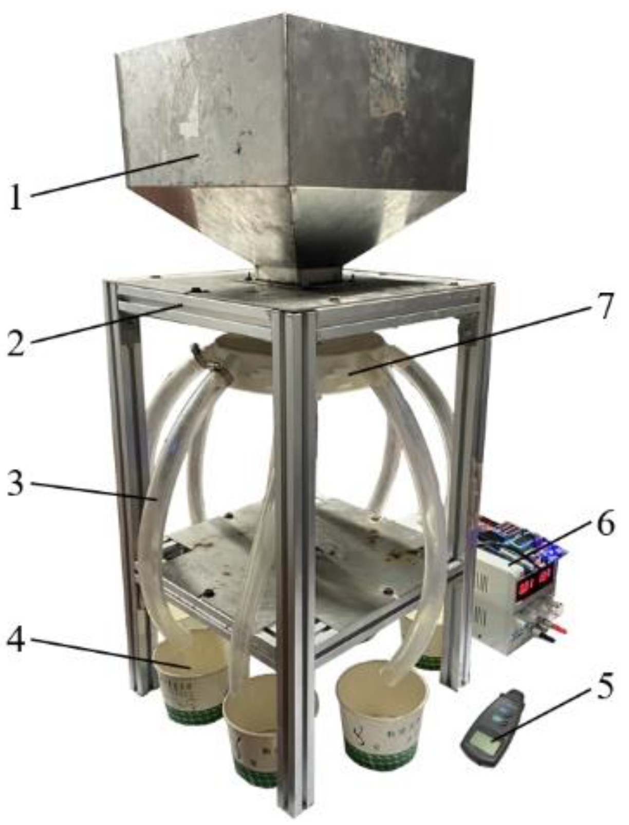
2.4. Fertilizing Performance Bench Tests

To further verify the fertilizing performance of the 3D-printed optimized FA with high-precision photosensitive resin, Stanley compound fertilizer was used as the test material to fertilize the FA with the customized bench at the 80~130 r/min, a tilt of 0° (i.e., horizontal state), and 5° performance test, and each trial was repeated three times in each experiment and averaged. The bench and ASCD-optimized FA are shown in Figure 5. In the experiment, a laser velocimeter (with a speed of SW6234C) was used to measure the rotation speed of the FA. A mega meter adjustable DC power RXN-3005D was used as the power supply. The variation coefficients of intra-row fertilization amount consistency, inter-row fertilization amount consistency, and fertilization amount stability were used as indicators.

2.5. Field Tests

To further verify the adaptability of the optimized FA to complex field conditions, we used the variation coefficient of the fertilization amount in the Agricultural Industry Standard of the People’s Republic of China NY/T1143-2006 Technical Specifications for Quality Evaluation of Planters as the evaluation basis [32]. Based on the 2BYQ-8 rapeseed seeder platform, a field test was carried out at the Jianli Experimental Demonstration Base in Hubei, as shown in Figure 6. The supporting power was a tractor (Dongfanghong LX954-C), the granular fertilizer was Stanley compound fertilizer, and the fertilizer rate was 525 kg/hm2. Combined with the field operation speed of the machine, the experiments were carried out at tractor travel speeds of approximately 4, 5, and 5.8 km/h, which corresponded to fertility apparatus rotation speeds of 100, 110, and 120 r/min, respectively. The tractor continuously traveled for 30 s in each trial, and each trial was repeated three times in each experiment. In the experiment, we used a fertilizer bag to receive each fertilizing pipe granular fertilizer and weighed it.

3. Results

3.1. Simulation Test Results

3.1.1. Simulation Test Result of Fertilizing Performance of Fertilizer Apparatus in Horizontal State

Table 1 describes the simulation process of the three FAs constructed according to three different ASCD busbars. As shown in Table 1, the three FAs had significant differences in the granular fertilizer filling process. The optimized FA granular fertilizer filled quickly, and the fertilizer chamber was filled with granular fertilizer when the ASCD was not rotating. A stable and continuous fertilizer flow was formed after rotating for 0.15 s. In the case of GI-curvature of busbar’s top-to-bottom surface, the filling speed was lower than that of the optimized FA granular fertilizer with GD-curvature. When the ASCD did not rotate or rotated for 0.15 s, the fertilizer chamber was not filled with fertilizer, which occurred after 0.6 s. The ASCD busbar with a 0-curvature of FA had a minimal filling speed. When the ASCD did not rotate, the fertilizer chamber was seriously underfilled. There were still severe vacancies at 0.15 s and 0.6 s of rotation, and the granular fertilizer was filled with the fertilizer chamber at 1.6 s of rotation. This shows that the FA had a better filling ability after optimizing the ASCD. The fertilization directly influenced the fertilizing performance by changing the variation coefficients of fertilizing amount stability, inter-row fertilizing amount consistency, and intra-row fertilizing amount consistency of the FA under different rotation speeds.
Table 2 shows the variation coefficients of fertilizing amount stability, inter-row fertilizing amount consistency, and intra-row fertilization stability of different forms of FA at different rotation speeds. As observed, under the same coned disk rotation speed, the ASCD busbar with GD-curvature exhibited lower variation coefficients of fertilizing amount stability, inter-row fertilizing amount consistency, and intra-row fertilization stability than GI- and 0-curvature ones, which was mainly related to the filling speed and effect of the FA. When the coned disk rotation speed increased gradually, the variation coefficients of fertilizing amount stability and inter-row fertilizing amount consistency of the three FAs showed a decreasing trend, and its variation coefficients of stability did not change significantly with the coned disk rotation speed. The variation coefficient of intra-row fertilization stability of different forms of fertility apparatus at different rotation speeds was small, indicating that the fertilizing amount in each pipeline of the fertility apparatus was stable and the fertilizing performance was reliable.

3.1.2. Simulation Test Result on Fertilizing Performance of Fertilizer Apparatus in a Tilted

The test results are shown in Figure 5. Herein, 1~8 represent the fertilizing pipe numbers, while the blue color represents the ASCD busbars with a GD in the FA fertilizing amount of each row, red represents those with a GI in FA fertilizing amount for each row, and green represents those with 0-curvatures in FA fertilizing amount of each row. The data at the top of the radar map are the corresponding variation coefficients of inter-row fertilizing amount consistency.
According to the distributions of granular fertilizer in different pipes in Figure 7, the lowest fertilizer rate was observed in the ASCD busbar with 0-curvature. The other two types of FA had slight rate differences. When the FA rotation speed remained unchanged, and its tilt was increased, the difference in the amount of fertilizing within each fertilizing pipe of the same FA also increased. Moreover, the amount of granular fertilizer discharged from fertilizing pipes 4 and 5 increased significantly and could be ranked in decreasing order as follows: GD-, GI-, and 0- curvatures. When the FA tilt remained unchanged, and the rotation speed increased, the difference in the amount of fertilizing within each fertilizing pipe of the same FA gradually dropped. According to the variation coefficients of inter-row fertilization amount consistency shown in Figure 7, at the same tilt, with the increased rotation speed, the variation coefficients of inter-row fertilization amount consistency of the three FAs all showed a decreasing trend. At the same rotation speed, the variation coefficients of inter-row fertilization amount consistency of the three FAs tended to increase with tilt. At the same rotation speed and tilt values, the variation coefficient of inter-row fertilizing amount consistency of the ASCD busbar top-to-bottom curvature with gradually decreasing FA was lower than that of the other two forms of the FA. In addition, the inter-row fertilization amount consistency of the ASCD busbar with 0-curvature was the worst among the three FAs under study. It can be seen from the above comparative experiments that the ASCD busbar with GD-curvature (hereinafter called the optimized FA) had the best performance, meeting all requirements of fertilizer discharge quality.

3.1.3. Analysis of the Internal Mechanism of Fertilizing Performance Differences

As discussed above, the optimized FA had the best fertilizing performance. To further explore the internal mechanism of the difference in fertilizing performance of granular fertilizer in different FAs, we selected three FAs after stable fertilization (after the FA was rotated for 0.2 s, that is, at 1.2 s) as the representative granular fertilizer, indicated by the red dots in Figure 8a. (Granule 1 was located at the outermost edge of the apex of the fertility apparatus ASCD near the inner wall of the spiral disturbance cup, and Granule 2 was located at the apex of the fertility apparatus ASCD.) The EDEM post-processing software was used to analyze the speed change of granular fertilizer in the direction of the X-axis (located on the plane formed by the center of each fertilizing pipe-discharge port, from the axis of the FA to the center of the no. 5 fertilizing pipe discharge port) in different forms of FA, as shown in Figure 8b,c (here, blue, red, and green curves represent speed variations of granular fertilizers in the ASCD busbars with GI-, GD-, and 0-curvatures, respectively).
As observed, the selected granular fertilizer had irregular velocity fluctuations in the horizontal X-axis direction first, indicating that the granular fertilizer moved to the lower end of the FA under the effect of the disturbance of the spiral disturbance cup at this time. After 1.8 s, a regular fluctuation of the speed in the horizontal X-axis direction appeared, indicating that the granular fertilizer entered the fertilizer chamber and moved to the outer edge of the FA under the action of the ASCD surface and the rotation of the FA. After fluctuating for some time, the granular fertilizer loses its speed in the horizontal X-axis direction, indicating that the granular fertilizer has been discharged from the fertilizer discharge port at this time. The time for the two granular fertilizers selected in the optimized FA to be discharged from the FA was shorter than that of the other two types of FA. Combined with the above simulation analysis and comparison experiments, it can be seen that the movement time of granular fertilizer in the FA is an essential factor affecting the fertilizing performance of granular fertilizer. The shorter the time, the faster the fertilizer chamber will be filled. It should be ensured that the fertilizer chamber is filled with granular fertilizer and a stable fertilizer flow is formed and discharged from the fertilizer discharge port, which is beneficial to improve the performance of the FA and verifies the correctness of the adopted theory. To verify the working quality of the optimized FA, further verification experiments were carried out on the FA performance.

3.2. Bench Test Results

The test results on FA fertilizing performance are listed in Table 3.
As observed, the variation coefficients of inter-row fertilization amount consistency and fertilizer amount stability decreased with increasing FA rotation speed when the FA was in the horizontal and tilted states. When the FA was in a horizontal state, the variation coefficient of inter-row fertilization amount consistency did not exceed 8.57%, and the variation coefficient of fertilization amount stability was below 5.68%. When the FA was tilted, the variation coefficient of inter-row fertilization amount consistency was below 10.23%, and the variation coefficient of fertilization amount stability was below 6.74%. In this situation, all indicators met the requirements of industry standards. The variation coefficient of intra-row fertilizing amount consistency remained unchanged with increased rotation speed. The variation coefficients of inter-row fertilization amount consistency and fertilization amount stability in the horizontal state were better than those in the fertilized tilted state, but the difference was insignificant. The variation coefficient of intra-row fertilizing amount consistency was below 3.52%. Compared with the simulation results, there was a specific difference between the bench test and simulation results, mainly related to a particular deformation of the FA. After 3D printing, the granular fertilizer achieved an irregular shape, deteriorating the bench test results. However, both test results properly reflected the test conditions. The bench test results met the requirements of industry standards, suggesting that the FA had good fertility and uniformity. In addition, it had good adaptability to the inclined state and met the operation quality requirements of complex field conditions.

3.3. Field Test Results

According to field test results statistics, the variation coefficient of inter-row fertilization amount consistency of the FA was below 7.68%, the variation coefficient of fertilization amount stability was below 4.95%, and the variation coefficient of intra-row fertilization amount consistency was below 3.57%. All numbers met the industry standard requirements for completing the field fertilization operations. At the same time, the performance parameters of the fertilizer apparatus are better than those of the mainstream fluted roller fertilizer apparatus [33]. It showed that the optimized design of the fertilizer apparatus was more suitable for the simultaneous fertilization of rape sowing.

4. Conclusions

This study is based on a theoretical analysis. An arc-shaped coned disk with the GD-curvature was optimally designed. The fertilizer apparatus designed has positive significance for improving the synchronous fertilization level of rape seeding, improving the utilization rate of fertilizer, reducing the amount of fertilizer, and promoting the green development of agriculture in the middle and lower reaches of the Yangtze River.
With the same coned disk rotation speed and tilting, the variation coefficients of fertilizing amount stability of the optimized FA, inter-row fertilizing amount consistency, and intra-row fertilization stability outperformed ASCD busbars with gradually increasing and zero curvatures. Bench tests of the FA revealed that the variation coefficient of inter-row fertilizing amount consistency of the FA was lower than 10.23%, the variation coefficient of fertilizing amount stability was lower than 6.74%, and the variation coefficient of intra-row fertilizing amount consistency was lower than 3.52%. Field tests of the FA revealed that the variation coefficient of inter-row fertilizing amount consistency was lower than 7.68%, the variation coefficient of fertilizing amount stability was lower than 4.95%, and the variation coefficient of intra-row fertilizing amount stability was lower than 3.57%. All parameters were better than the industry standard, demonstrating that the FA had good fertilizing performance and met the quality requirements of field fertilization operations.

Author Contributions

Conceptualization, X.L.; methodology, X.L.; software, X.L.; validation, J.W.; formal analysis, Q.L.; data curation, E.L. writing—original draft preparation, X.L.; writing—review and editing, Q.L.; visualization, D.Y.; supervision, G.L.; project administration, L.Y. All authors have read and agreed to the published version of the manuscript.

Funding

This research was funded by the following fund projects: the Key Scientific Research Projects of Henan Province Colleges and Universities (20A210029); Mechanical Manufacturing and its Automation Key Disciplines of Pingdingshan University (PXY-JXZDXK-202306).

Institutional Review Board Statement

Not applicable.

Data Availability Statement

Not applicable.

Conflicts of Interest

The authors declare no conflict of interest.

References

  1. Wu, S.; Liu, H.; Liu, S.; Wang, Y.; Gu, B.; Jin, S.; Lei, Q.; Zhai, L.; Wang, H. Review of current situation of agricultural non-point source pollution and its prevention and control technologies. Strateg. Study CAE 2018, 20, 23–30. (In Chinese) [Google Scholar] [CrossRef]
  2. Chen, A. Research strategy of agricultural non-point source pollution. J. Nanjing Tech Univ. Soc. Sci. Ed. 2018, 17, 8–18. (In Chinese) [Google Scholar]
  3. Huang, Y.; Liu, P.; Gan, M.; Nebiyou, L.; Wang, H.; Gan, X.; Guo, L.; Ma, Y. Application of GIS technology in research of agricultural non-point source pollution. Soils Fertil. Sci. China 2020, 60, 279–285. (In Chinese) [Google Scholar]
  4. Min, J.; Kong, X. Research progress on agricultural non-point source pollution in China. J. Huazhong Agric. Univ. Soc. Sci. Ed. 2016, 35, 59–66. [Google Scholar]
  5. Han, Y.; Jia, R.; Tang, H. Research status and development suggestions of precision variable-rate fertilization machine. Agric. Eng. 2019, 9, 1–6. (In Chinese) [Google Scholar]
  6. Tang, H.; Wang, J.; Xu, C.; Zhou, W.; Wang, J.; Wang, X. Research progress analysis on key technology of chemical fertilizer reduction and efficiency increase. Trans. Chin. Soc. Agric. Mach. 2019, 50, 1–19. (In Chinese) [Google Scholar]
  7. Liu, X.; Wang, X.; Chen, L.; Zhang, C.; Liu, W.; Ding, Y. Design and experiments of layered and quantitative fertilization device for rapeseed seeder. Trans. CSAE 2021, 37, 1–10. (In Chinese) [Google Scholar]
  8. Shi, Y.; Chen, M.; Wang, X.; Morice, O.; Li, C.; Ding, W. Design and experiment of variable-rate fertilizer spreader with centrifugal distribution cover for rice paddy surface fertilization [J/OL]. Trans. Chin. Soc. Agric. Mach. 2018, 49, 86–93. (In Chinese) [Google Scholar]
  9. Han, B.; Liu, Q.; Gao, Y.; Yang, S.; Guo, C.; Dong, X.; Li, Y. Numerical simulation and experiment of seeding performance of seed and medicine mixing device of soybean coating machine. J. Northeast. Agric. Univ. 2020, 51, 79–86. (In Chinese) [Google Scholar]
  10. Cool, S.; Pieters, J.; Mertens, K.C.; Hijazi, B.; Vangeyte, J. A simulation of the influence of spinning on the ballistic flight of spherical fertilizer grains. Comput. Electron. Agric. 2014, 105, 121–131. [Google Scholar] [CrossRef]
  11. Xu, B.; Wang, S.; Wu, A.; Ma, B.; Chen, Y.; Xue, Z.; Wang, A. Design of spreading machinery special for greenhouses. J. Agric. Mech. Res. 2017, 39, 158–161. (In Chinese) [Google Scholar]
  12. Lü, J.; Shang, Q.; Yang, Y.; Li, Z.; Li, J.; Liu, Z. Performance analysis and experiment on granular fertilizer spreader with swing disk. Trans. CSAE 2016, 32, 16–24. (In Chinese) [Google Scholar]
  13. Jia, F.; Yao, L.; Han, Y.; Wang, H.; Shi, Y.; Zeng, Y.; Jiang, L. Simulation and optimal design of uniform plate of brown rice based on discrete element method. Trans. CSAE 2016, 32, 235–241. [Google Scholar]
  14. Lan, Z. Design and Experiment of Key Equipment in Rape Plot Seeder. Ph.D. Thesis, Huazhong Agricultural University, Wuhan, China, 2017. (In Chinese). [Google Scholar]
  15. Yang, R.; Zhang, X.; Li, J.; Shang, S.; Chai, H. Parameter optimization and experiment on cone canvas belt type seed-metering device. Trans. CSAE 2016, 32, 6–13. [Google Scholar]
  16. Xu, P.; Yang, R.; Shang, S.; Yang, H.; Cui, G.; Liu, L. Experimental study on damaged potato of secondary conveying and separating device. J. Agric. Mech. Res. 2018, 40, 45–49. (In Chinese) [Google Scholar]
  17. Yang, C.; Shang, S.; Yang, R.; Wang, C. Theoretical study on the cone-centrifugal seed-metering device. J. Agric. Mech. Res. 2015, 37, 63–66. (In Chinese) [Google Scholar]
  18. Hu, D.; Zhang, L.; Ma, Y.; Dong, W. Performance analysis and experiment of variable fertilizer spreader based on EDEM. J. Agric. Mech. Res. 2022, 44, 177–181. (In Chinese) [Google Scholar]
  19. Lü, J.Q.; Sun, H.; Dui, H.; Li, Z.; Li, J.; Yu, J. Optimization and experiment of fertilizer particle motion model in conical spreading disk. Trans. Chin. Soc. Agric. Mach. 2018, 49, 85–91. (In Chinese) [Google Scholar]
  20. Yan, H.; Tang, Z.; Meng, X.; He, Y. Design and performance test of centrifugal type of variable rate fertilizer. J. Gansu Agric. Univ. 2017, 52, 144–149. (In Chinese) [Google Scholar]
  21. Villette, S.; Pirone, E.; Miclet, D. Hybrid centrifugal spreading model to study the fertilizer spatial distribution and its assessment using the transverse coefficient of variation. Comput. Electron. Agric. 2017, 137, 115–129. [Google Scholar] [CrossRef]
  22. Sun, Z.; Chen, J.; Duan, J.; Xue, K.; Ou, Z. Design of test bench for centrifugal fertilizer spreader. Mod. Agric. Equip. 2019, 40, 33–37. (In Chinese) [Google Scholar]
  23. Yang, L.; Chen, L.; Zhang, J.; Sun, H.; Liu, H.; Li, M. Test and Analysis of Uniformity of Centrifugal Disc Spreading. Trans. Chin. Soc. Agric. Mach. 2019, 50, 108–114. (In Chinese) [Google Scholar]
  24. Hu, Y.G.; Yang, Y.C.; Xiao, H.R.; Li, P. Simulation and parameter optimization of centrifugal 1fertilizer spreader for tea plants. Trans. Chin. Soc. Agric. Mach. 2016, 47, 77–82. (In Chinese) [Google Scholar]
  25. Guo, H.; Fang, L.; Ye, Y.; Yang, W.; Wang, Z.; Liu, Z. Design and test of the disk-type variable-rate fertilizer feeder based on EDEM. J. Mach. Des. 2019, 36, 67–71. (In Chinese) [Google Scholar]
  26. Liu, C.; Li, Y.; Song, J.; Ma, T.; Wang, M.; Wang, X.; Zhang, C. Performance analysis and experiment on fertilizer spreader with centrifugal swing disk based on EDEM. Trans. CSAE 2017, 33, 32–39. (In Chinese) [Google Scholar]
  27. Wang, Y.Q.; Wei, M.; Dong, W.C.; He, J.; Han, C.; Jiang, Z. Design and parameter optimization of a soil mulching device for an ultra-wide film seeder based on the discrete element method. Processes 2022, 10, 2115. [Google Scholar] [CrossRef]
  28. Sugirbay, A.; Hu, G.; Chen, J.; Mustafin, Z.; Muratkhan, M.; Iskakov, R.; Chen, Y.; Zhang, S.; Bu, L.; Dulatbay, Y.; et al. A study on the calibration of wheat seed interaction properties based on the discrete element method. Agriculture 2022, 12, 1497. [Google Scholar] [CrossRef]
  29. Liu, X.; Ding, Y.; Shu, C.; Liu, W.; Wang, K.; Du, C.; Wang, X. Design and experiment of spiral disturbance cone centrifugal FA. Trans. CSAE 2020, 36, 34–43. (In Chinese) [Google Scholar]
  30. Liu, X.; Ding, Y.; Shu, C.; Wang, K.; Liu, W.; Wang, X. Mechanism analysis and test of disturbance and blockage prevention of spiral cone centrifugal FA. Trans. Chin. Soc. Agric. Mach. 2020, 51, 44–54. (In Chinese) [Google Scholar]
  31. Van, L.; Tijskens, E.; Dintwa, E.; Rioual, F.; Vangeyte, J.; Ramon, H. EDEM simulations of the particle flow on a centrifugal fertilizer spreader. Powder Technol. 2009, 190, 348–360. [Google Scholar]
  32. NY/T 1143-2006; Technical Specifications of Quality Evaluation for Drills. Ministry of Agriculture of the People’s Republic of China: Beijing, China, 2006.
  33. Gao, L.; Chen, H.; Liao, Q.; Zhang, Q.; Li, Y.; Liao, Y. Experiment on fertilizing performance of dynamic tilt condition of seeder with deep fertilizer for rapeseed. Trans. Chin. Soc. Agric. Mach. 2020, 51, 64–72. (In Chinese) [Google Scholar]
Figure 1. FA structure: 1—upper shell; 2—spiral disturbance cup; 3—ASCD; 4—fertilizing pipe; 5—lower shell; 6—drive shaft.
Processes 11 00199 g001
Figure 2. Schematic diagram of the forces on the cone disc for granular fertilizers.
Processes 11 00199 g002
Figure 3. Structure of ASCD busbar.
Processes 11 00199 g003
Figure 4. Busbar pattern of the arc-shaped cone disc: ① a gradually declined (GD)-curvature; ② a gradually increased (GI)-curvature; ③ a zero (0)-curvature.
Processes 11 00199 g004
Figure 5. Bench test of FA: 1—fertilizer box; 2—bench; 3—fertilizing pipe; 4—fertilizer box; 5—laser velocimeter; 6—mega-meter adjustable DC power; 7—spiral disturbance cone centrifugal FA.
Processes 11 00199 g005
Figure 6. Field test of FA: 1—spiral cone centrifugal FA; 2—2BYQ-8 rapeseed seeder.
Processes 11 00199 g006
Figure 7. The adaptability of the tilted FA.
Processes 11 00199 g007
Figure 8. Movement of granular fertilizer: (a) selected location of granular fertilizer; (b) speed curves of granular fertilizer 1 in different FAs; (c) speed curves of granular fertilizer 2 in different FAs.
Processes 11 00199 g008
Table 1. Simulation of different forms of FA.
Rotation time/sBusbar Forms of ASCD
GD-CurvatureGI-Curvature0-Curvature
0 Processes 11 00199 i001 Processes 11 00199 i002 Processes 11 00199 i003
0.15 Processes 11 00199 i004 Processes 11 00199 i005 Processes 11 00199 i006
0.6 Processes 11 00199 i007 Processes 11 00199 i008
1.6 Processes 11 00199 i009
Table 2. Analysis of the fertilizing performance of various forms of FA.
FA TypeConed Disk
Rotation Speed/(r·min−1)
Fertilizing Pipe NumberVariation Coefficient of Inter-Row Fertilizing Amount Consistency/%Variation Coefficient of Fertilizing Amount Stability/%
12345678
Variation Coefficient of Intra-Row Fertilizing Amount Consistency/%
ASCD busbar with GD-curvature801.682.191.771.522.242.161.812.297.214.63
901.882.660.910.881.091.641.210.975.923.93
1001.471.151.611.642.191.231.220.945.053.28
1100.860.990.761.341.050.891.861.64.273.05
1201.161.141.350.850.831.160.871.233.782.57
1300.982.071.320.941.221.371.431.422.752.33
ASCD busbar with GI-curvature802.992.482.363.072.582.623.082.998.574.91
903.472.681.681.891.712.011.772.447.284.25
1001.962.272.442.992.412.021.752.036.473.66
1101.681.682.131.851.662.662.41.695.323.44
1201.981.961.641.622.161.652.011.964.182.94
1302.861.781.742.022.182.232.242.133.192.57
ASCD busbar with 0-curvature802.844.294.172.964.053.563.892.319.326.09
902.822.422.493.002.403.322.892.508.155.37
1002.652.572.742.792.712.521.972.606.894.75
1102.022.472.292.042.292.563.062.435.944.56
1201.881.501.742.222.022.122.552.475.024.03
1302.361.842.242.182.132.052.252.114.253.67
Table 3. Bench test results on fertilizing performance.
Tilt/°Coned Disk
Rotation Speed/(r·min−1)
Fertilizing Pipe NumberVariation Coefficient of Inter-Row Fertilizing Amount Consistency/%Variation Coefficient of Fertilizing Amount Stability/%
12345678
Variation Coefficient of Intra-Row Fertilizing Amount Consistency/%
0802.322.471.551.872.521.452.092.898.575.68
902.012.422.421.091.021.221.841.397.295.14
1001.872.391.912.211.451.702.242.115.884.55
1101.461.601.081.471.582.161.651.754.614.29
1201.101.461.171.441.201.281.122.044.053.71
1301.311.061.391.381.571.171.831.322.673.06
5803.522.672.172.092.311.663.442.9110.236.74
903.401.952.191.822.142.413.042.069.076.25
1001.902.241.091.922.351.851.911.758.645.42
1101.711.401.531.901.822.192.231.776.375.01
1202.001.841.461.640.851.481.872.325.614.35
1301.391.871.571.571.781.591.471.644.393.61
Disclaimer/Publisher’s Note: The statements, opinions and data contained in all publications are solely those of the individual author(s) and contributor(s) and not of MDPI and/or the editor(s). MDPI and/or the editor(s) disclaim responsibility for any injury to people or property resulting from any ideas, methods, instructions or products referred to in the content.

