Article

3D Printing Multi-Channel Large Volume Microchannel Reactor for Enhanced Removal of Low-Concentration NOx Flue Gas

1
Faculty of Metallurgical and Energy Engineering, Kunming University of Science and Technology, Kunming 650093, China
2
State Key Laboratory of Complex Nonferrous Metal Resources Clean Utilization, Kunming University of Science and Technology, Kunming 650093, China
3
Kunming Institute of Precious Metals, Kunming 650106, China
*
Author to whom correspondence should be addressed.
Processes 2023, 11(1), 158; https://doi.org/10.3390/pr11010158
Submission received: 3 November 2022 / Revised: 29 December 2022 / Accepted: 30 December 2022 / Published: 4 January 2023
(This article belongs to the Special Issue Gas Emissions Control and Utilization)

Abstract

:
Compared with conventional reactors that are designed by traditional micromachining technology, the use of 3D-printing technology to manufacture multichannel large-volume microchannel reactors as reaction equipment to remove low-concentration NOX by the wet method is simple and convenient, and the processing cost is low. The results showed that when the concentration of NO was 400 ppm, the mixed solution of (NH2)2CO mass fraction of 3% and H2O2 concentration of 0.5 mol/L was used, and the flow rates of gas and liquid were 100 mL/min, respectively, under the experimental conditions of pH = 11, solution temperature of 20 °C and 500 mL solution recycling for 20 min, the best removal effect of NOX was achieved, and the removal efficiency was 100%. When the O2 content in the flue gas was increased and the number and length of microchannels were increased, the NOX removal efficiency increased accordingly, which was conducive to the rapid and efficient reaction. The application of the microchannel reactor presents a new method for improving the air quality and reducing environmental pollution in the future.

Graphical Abstract

1. Introduction

Social development and technological progress have afforded human beings better lives; however, consequently, environmental problems have become increasingly more prominent. Among them, air pollution issues, which are closely related to human life, have received a great deal of attention. Nitrogen oxide pollution is the main form of air pollution, and it does substantial harm to the natural environment and human health [1]. The main source of NOX in the atmosphere is the large amount of exhaust gas that is released by the major steel plants, nonferrous metal smelters and thermal power and chemical plants [2,3]. Therefore, reducing the NOX that is produced in the industrial production process is the key to solving the problem of environmental pollution.
Wet flue gas denitrification technology is based on wet desulfurization technology, with the addition of certain additives to the solution so that it can absorb NOX [4,5]. According to the different action modes of the additives and NOX, it can be mainly divided into oxidation absorption method [6,7,8,9], reduction absorption method [10,11] and complex absorption method [12,13]. The technology also overcomes the disadvantages of conventional denitrification technology, such as its complex process, large area, substantial investment and high operating cost [14]. Therefore, the development of wet flue gas denitrification technology, with its simple technical process, low operating cost and better operating performance, is an internationally important research trend in industrial flue gas treatment [15]. The key scientific problems that still need to be solved in the existing wet flue gas treatment process and tower equipment mainly include the following [16,17]: (1) NOx needs to be efficiently absorbed, and especially the solution medium that converts and absorbs NO; (2) the short gas-liquid contact time and long mass transfer distance make it difficult to achieve a gas-liquid absorption equilibrium; (3) the gas-liquid contact surface is insufficiently renewed; (4) due to the pressure difference between the gas and liquid, it is easy to form a short circuit; (5) the equipment is huge and the cost is high. Therefore, the limitations of conventional wet flue gas treatment process and tower equipment need to be solved urgently, and the development of efficient and closed gas-liquid reaction equipment is the key to solve this problem. The microchannel reactor system has low consumption and is highly efficient and safe. Because of these characteristics, it could transform the low-efficiency and high-consumption processes of the traditional metallurgical industry, such as waste treatment, heat exchange and mixing, making it possible to develop new energy-saving processes to promote the industrial upgrading of the metallurgical industry.
The development and use of 3D printing to manufacture devices with complex 3D structures has also substantially improved in the field of chemical applications [18]. The unique advantages of 3D printing have driven research into the additive manufacturing of microchannel reactor devices, which has begun to expand the general understanding of the unique advantages of 3D-printing microchannel reactors and the key areas for further development [19,20]. Compared with traditional micromachining technology, 3D-printing microchannel reactor technology has advantages in terms of the rapid design and processing, wide material adaptability and low cost. Because the physical size of the channels of the microchannel reactor is reduced to the micrometer or even nanometer level [19], the gradients of the physical quantities of the fluid, such as the temperature, pressure, concentration and density, rapidly increase, which results in a substantial increase in the driving force of the heat and mass transfer, which creates heat transfer. The coefficient is increased by one order of magnitude, and the mass transfer time is reduced by one order of magnitude [21]. Due to the improvement in the reaction speed, the reaction equipment and reaction system can be substantially reduced, which improves the safety of the reaction process and the land investment. Moreover, the consumption of the materials can also be substantially reduced [22]. In recent years, researchers have widely studied and applied gas-liquid microreactors in chemical biology and other fields. Zhu et al. [23] studied the gas-liquid distribution and mass transfer of the CO2 absorbed into a sodium glycine aqueous solution in parallel multichannel microreactors, proving that they have a good mass transfer performance. Yang et al. [24] studied the gas-liquid mass transfer and mixing in zigzag microreactors under ultrasonic oscillation, and they found that the zigzag microchannels could effectively enhance the gas-liquid mass transfer. Researchers have also made substantial progress in the scale-up design of microchannel reactors. Numbering, which is the parallel arrangement of multiple identical channels or reactors, is a common method for the scaling up of microreactors [25,26,27,28]. This method preserves the fluid dynamics and transfer characteristics that are associated with the microenvironment, which allows the reactions to be performed under the same conditions as a single microreactor. In addition, the amplification design is carried out by increasing the length of the channel and keeping the diameter of the channel constant [28,29]. However, increasing the size of the channel leads to substantial changes in the fluid dynamics and transfer characteristics. In addition to the traditional amplification method, Kai Wang et al. [30] proposed a new amplification strategy for the microsieve distributed reactor: the similarity amplification + quantity amplification + numerical simulation method. Similarity amplification can improve the processing capacity of the core unit, quantity amplification can increase the reactor output and numerical simulation can ensure the flow, heat transfer and stability of the process. Hessel et al. [31] used falling film microchannel reactors and microbubble columns to absorb CO2 gas. According to the experimental results, the absorption performance of the microchannel reactors for the CO2 gas was superior to that of traditional equipment. Su et al. [32] used a microchannel reactor to study the absorption of H2S gas. According to the experimental results, the H2S absorption rate in the microchannel was extremely high, and the specific surface area of the gas-liquid contact in the experiment reached 11,100 m2/m3. Therefore, it is feasible to study the gas-liquid reaction by using a microchannel reactor, as well as its removal of NOX gas.
In this study, aiming at the problem that it is difficult to remove the nitrogen oxide gas produced when a precious metal smelting company uses aqua regia to dissolve precious metals, in which the main component of nitrogen oxide is NO, a multi-channel high-flux micro-channel reactor was designed and the wet process was used to remove NOX flue gas with the mixed solution of (NH2)2CO and H2O2. According to the experiments, the NOX was completely removed in the microchannel reactor. The equipment has the following advantages: a simple structure; convenient operation; low maintenance cost; small floor space; high efficiency; easy treatment of the removal liquid; low pollutants. Thus, it can effectively protect the environment and will have wide application prospects in the future.

2. Experimental Materials and Methods

2.1. Materials

The simulated flue gas required for the experiment was prepared with N2, NO, and O2 gases in a certain proportion. Among them, N2 and O2 were provided by cylinder gas with a purity of 99.999% (Sichuan Messer Gas Products Co., Ltd., Chengdu, China), and the NO concentration was 0.05% (filling gas is N2). Urea ((NH2)2CO), sodium hydroxide (NaOH), potassium permanganate (KMnO4) and anhydrous calcium chloride (CaCl) were purchased from Tianjin Zhiyuan Chemical Reagent Co., Ltd. (Tianjin, China). Hydrogen peroxide (H2O2, 30%) was purchased from Chongqing Chuangdao Chemical Co., Ltd. (Chongqing, China). Nitric acid (HNO3) was purchased from Maoming Xiongda Chemical Co., Ltd. (Maoming, China). (All chemicals were of analytical grade and used as received. All solutions in this study were prepared with deionized water.

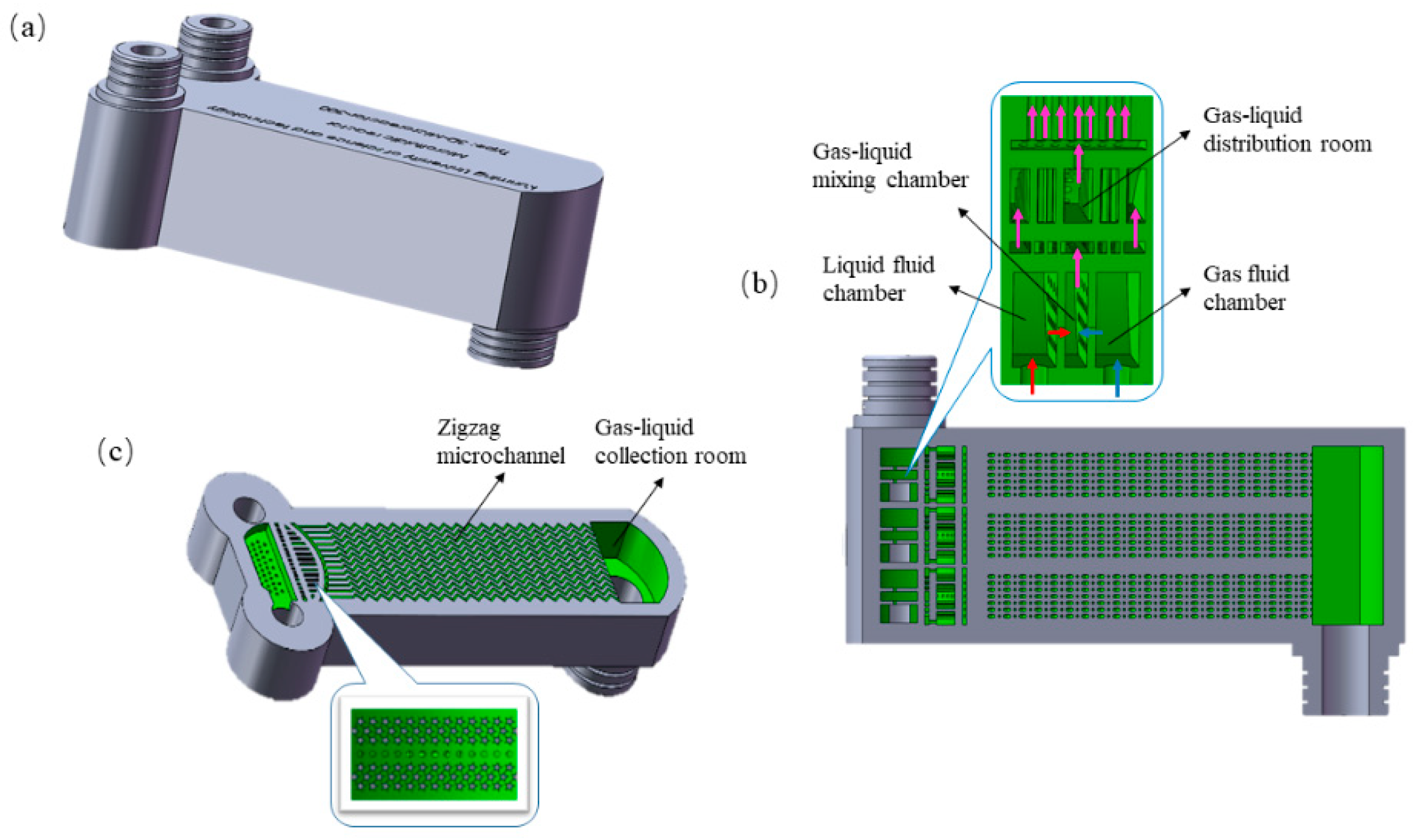
2.2. Microchannel Reactor Design and 3D Printing

The multi-channel large volume microchannel reactor manufactured by the 3D printing technology used in the experiment was designed through the three-dimensional Graphics Software Solidworks 2016. Eskin et al. [33] investigated the influence of the cross section and length of the microchannel on the gas-liquid mass transfer, and they found that the gas-liquid mass transfer coefficient in the microchannel increased as the cross-sectional area of the channel decreased. Pennemann et al. [34] studied the influence of the microchannel structure and operating conditions on the mass transfer, and they found that a plugged flow and backmixing occurred in the microchannel when its diameter and the velocity of the liquid phase increased. Chasanis et al. [35] designed contactors that are suitable for a gas-liquid two-phase flow. Porous screens are placed in the microchannel to both stabilize the flow pattern and provide a larger phase contact area for the two gas-liquid phases. Therefore, in the design of the reactor, the cross-sectional area of the microchannel should be reduced as much as possible, the length of the microchannel should be increased and the gas-liquid phase should be separated by a sieve plate, which is more conducive to the reaction. According to a numerical simulation, the serrated microchannel forms a microvortex when fluid passes through (gas or liquid); thus, the researchers designed the microchannel in the reactor as a serrated microchannel [36]. To achieve a larger capacity of the reaction, they used the parallel method (i.e., using a large number of microchannels with the same structure for stacking) to scale up the design of the microchannel reactor, which has laid the foundation for the further industrial application of the wet nitrogen oxide removal technology of microchannel reactors. The gas-liquid two-phase distribution in parallel microchannels is still a difficult problem. Because of poor design, some channels can be filled with gas or liquid, which is a phenomenon known as “gas-liquid channeling” [37]. At present, two-phase flow distribution can be realized by branching [38], internal distribution [39] and external distribution [40]. The internal distribution was adopted in this experiment. To solve the problem of “gas-liquid channeling” in the built-in distributed microchannel reactor, a large diameter manifold can be set up to balance the pressure drop of each branch channel, or barriers can be set up at the entrance of each branch channel to increase the pressure in the distribution area. However, the gas-liquid two-phase flow in the large-diameter channel cannot reflect the fine characteristics of the micro-channel, so the second method is used to increase the uniformity of the two-phase distribution.
The microchannel reactor is mainly composed of a gas fluid chamber, liquid fluid chamber, gas-liquid mixing chamber, gas-liquid distribution chamber, gas-liquid collection chamber and multiple zigzag microchannels, as shown in Figure 1. Because the microchannel reactor is in an upright state when used, the two gas-liquid phases first enter the gas fluid and liquid fluid chambers from bottom to top inside the reactor, and they then flow into the gas-liquid mixing chamber through the sieve plate for mixing. The gas-liquid mixing chamber is connected to the gas-liquid distribution chamber through multiple columnar structures with triangular sections. After filling the gas-liquid distribution chamber, the gas-liquid phase enters the microchannel for a further mixing reaction, and it finally flows out into the gas-liquid collection chamber. The gas-liquid distribution chamber is a three-dimensional structure of a longitudinal stretched fan shape, in which a number of pentagram columns are evenly distributed. This structure not only makes the distribution of two gas-liquid phases more uniform, but it also makes it easier to divide them into small forms for an effective mixing reaction with the increase in the angles. The number of microchannels is 91, the characteristic size of the microchannels is 1 mm, the length of the zigzag mixing channel is 96.7 mm and the zigzag angle is 90°.
This study used a commercial 3D printer (Hunter, Flashforge Corporation, Jinhua, China), which used a layer-by-layer printing method to print from bottom to top. To ensure printing accuracy, the uv curing penetration depth was set to 50 μm and the curing time for each layer was set to 2.5 s. In the printing process does not require any additional operations, simple and fast. Compared with the conventional reactor designed by traditional micromachining technology, the use of 3D printing to manufacture reactors allows us to effectively avoid the problems of the traditional manufacturing complexity, high processing cost and difficult promotion [41,42,43]. The printing material used is photosensitive resin, its main component is about 30% acrylic ester, about 50% monomer (the main component is HDDA and TPGDA) as diluent, and a small part of auxiliary additives such as pigment and photosensitive initiator, etc.
In this experiment, three microchannel reactors with different structural sizes were designed and printed for comparison with conventional bubble reactors (Type I): (1) Type II, which is the microchannel reactor that shown in Figure 1; (2) Type III, the channel length increases by 30% while the number of channels remains unchanged; (3) Type IV, the channel length is increased by 30%, the number of channels is increased by 2/3, and the total volume is increased to 30 mL.

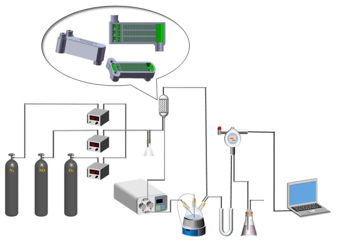
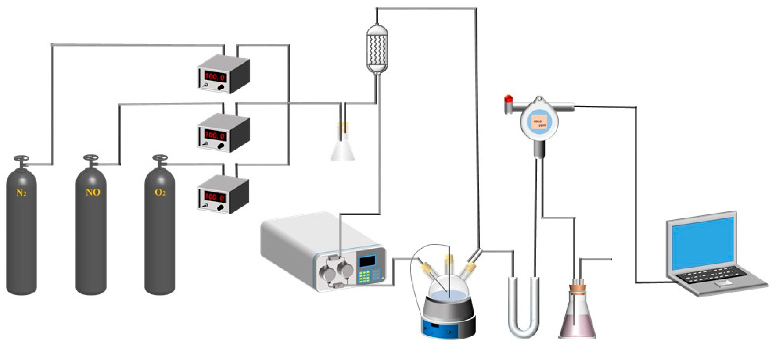
2.3. Multi-Channel High-Throughput Microchannel Reactor for NOX Removal

The experimental device is mainly composed of a gas distribution system, reaction system and analysis system (Figure 2). In terms of the gas distribution system, in this experiment, N2, O2 and NO cylinder gas were mixed to simulate the actual flue gas. The simulated flue gas concentration in this experiment was 400 ppm. Digital display current stabilizer (007, Beijing Qixing Huachuang Co., Ltd., Beijing, China) was used for gas mixing and then connected to the air inlet of the microchannel reactor.
In terms of the reaction system, the gas-liquid two-phase mixing reaction was carried out in a microchannel reactor. The (NH2)2CO and H2O2 solution was used as 500 mL of the removal liquid for removing NOX. The volume of the removal liquid in the subsequent experiments was 500 mL. The temperature of the solution was adjusted by magnetic stirring heating jacket (CLT-1A, Shanghai Lichen Bangxi Instrument Co., Ltd., Shanghai, China), and the temperature error was ±1 °C. A horizontal flow pump (2PB-1000III, Beijing Xingda Technology Development Co., Ltd., Beijing, China) was used to pump the removal liquid into the liquid phase end of the reactor, and the reaction time was 20 min. Used 1 mol/L sodium hydroxide solution and 1 mol/L dilute nitric acid solution to adjust the pH of the removal solution, and measured it with a digital pH meter (PHS-3C, Shanghai Yidian Scientific Instruments Co., Ltd., Shanghai, China).
In terms of the analysis system, before flue gas detection, the gas was dried by a gas dryer containing anhydrous calcium chloride to ensure the measurement accuracy and safety of the experimental equipment. The nitrogen oxide detector (OS60, Shenzhen Dongri Technology Co., Ltd., Shenzhen, China) was used for smoke detection. The computer was used to export and record the experimental data. During the experiment, the measured data were output every 120 s.
The subsequent tail gas treatment was absorbed by the KMnO4 solution to further purify the residual pollutants in the tail gas and avoid environmental pollution.

2.4. Calculation of NOx Removal Efficiency

The formula for calculating the NOx removal efficiency of the microchannel reactor is as follows:
Removal = C 1 C 2 C 1   × 100 %
where C1 is the NOX concentration at the gas phase inlet of the microchannel reactor, and C2 is the NOX concentration at the outlet of the microchannel reactor.

2.5. Calculation of Gas-Liquid Contact Time (T)

The contact time T of the gas-liquid two-phase in the microchannel reactor, in s, is calculated as follows:
T = V Q
where V is the total volume of the mixing channel in the microchannel reactor, T is the average contact time of the two phases in the mixing channel and Q is the total flow of the gas and liquid phases.

3. Experimental Results and Discussion

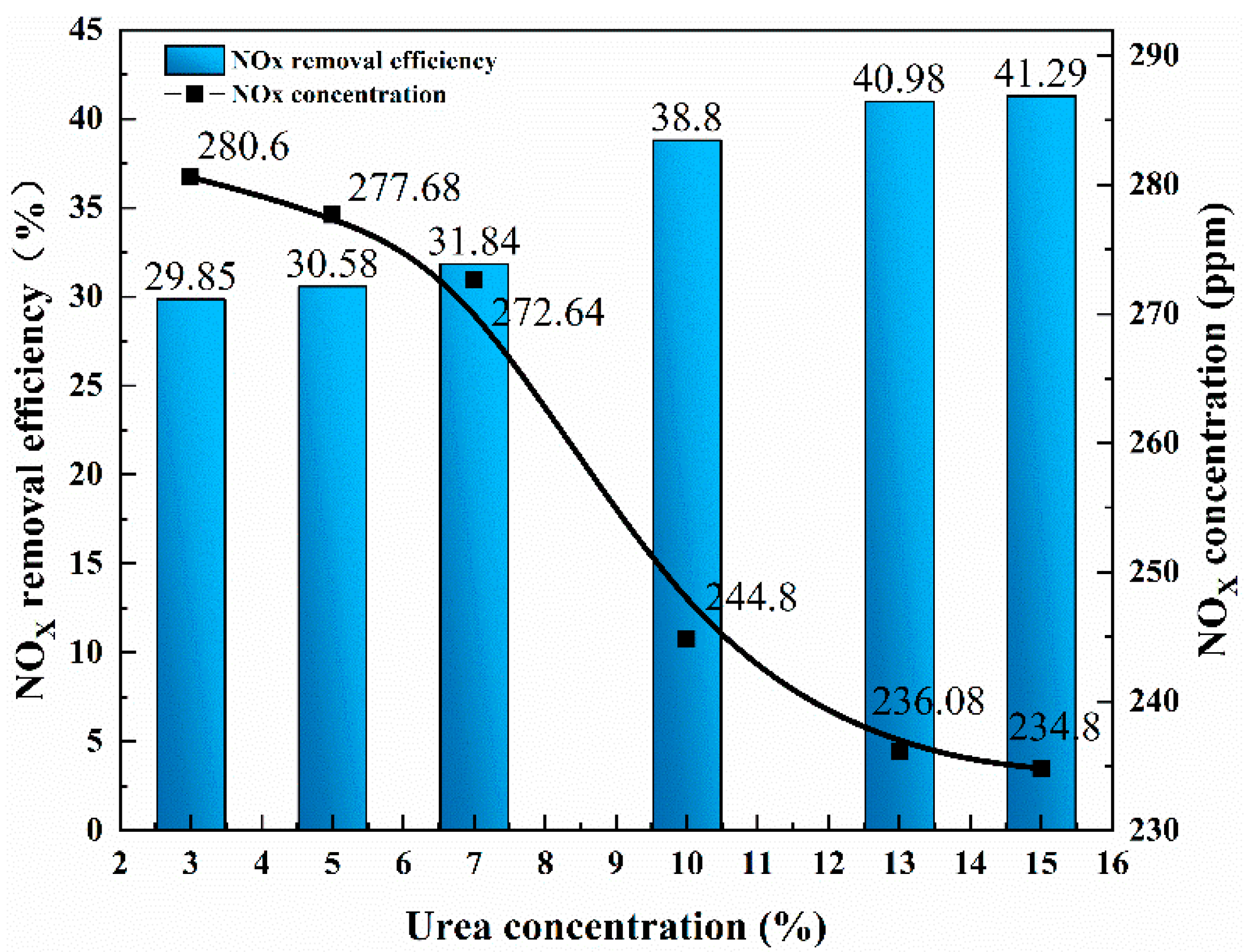
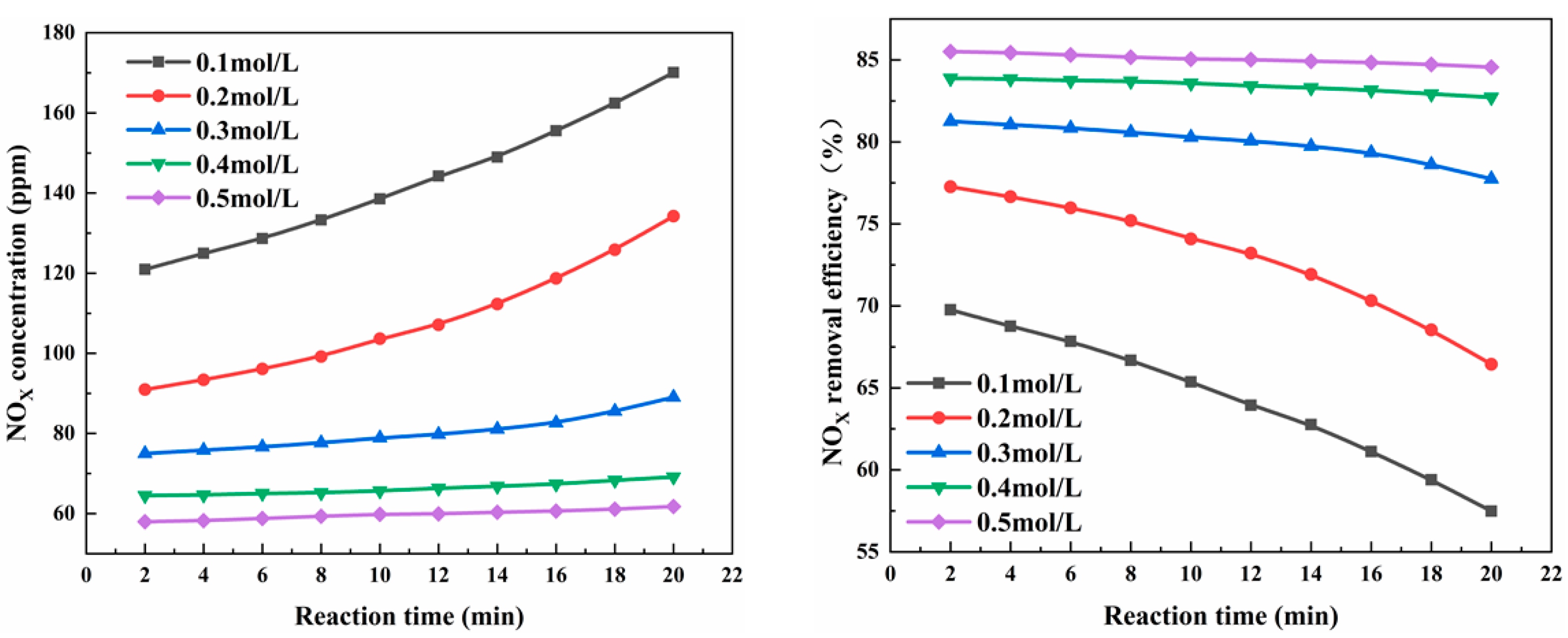
3.1. Effects of Different Concentrations of (NH2)2CO and H2O2 on NOX Removal Efficiency

Urea ((NH2)2CO), as a reducing agent, was an important factor in the experiment. Compared with other absorption solutions, urea is a cheap and nontoxic reactant that is easy to obtain in China. The reaction product of urea liquid phase denitrification has no other harmful byproducts, which makes it clean and safe. LaSalle et al. [44] studied the kinetic parameters of the chemical reaction of nitrous acid and urea in a closed stirred reactor. Wei et al. [6] investigated the NO removal characteristics of a NaClO2/(NH2)2CO solution for wet scrubbing, and they found that the urea had little negative effect on the NO removal efficiency and was of help in the NO2 emission reduction. Therefore, considering the denitrification efficiency and economy, this experiment firstly explores the optimal concentration of (NH2)2CO removal. The reaction conditions of the NOX removal device with the Type IV microchannel reactor were a gas and liquid flow of 150 mL/min and a reaction temperature of 20 °C. The experimental results are shown in Figure 3. With the increase in the (NH2)2CO concentration from 3% to 15%, the solution concentration increased by 5 times; however, the removal efficiency of the NOX only increased by 11.44%, and only slowly, which is because the influence of the urea on the NOX removal was related to two aspects: a chemical reaction and the physical properties. The reaction can accelerate the absorption rate of NOX. However, with the increase in the urea concentration, the viscosity of the removal solution increases, and the liquid diffusivity and solubility of the NOX decrease [6]. In practical application, from an economic perspective, the higher the concentration of the removal solution, the higher the operation cost. Therefore, the concentration of the removal solution cannot be indefinitely increased. Considering the removal efficiency and economy, the urea solution with a mass fraction of 3% was used as the reductant in the next experiments.
In this experiment, the optimal removal concentrations of (NH2)2CO and H2O2 were explored. H2O2, as the oxidant in the solution, and (NH2)2CO, as the reductant in the solution, cooperate with the microchannel reactor to enhance the removal of low-concentration NOX. The experimental principle is that the H2O2 in the solution components decomposes into HO·, oxidizes the NO with an extremely low water solubility into NOX, with a higher solubility, and then uses the (NH2)2CO in the solution to reduce it, thereby realizing the removal of nitrogen oxides. A Type IV microchannel reactor was used under the experimental conditions of reaction temperature 20 °C and flow rate of both gas and liquid 150 mL/min, and the experimental results were shown in Figure 4. During the reaction strengthening process of the two gas-liquid phases in the microchannel, a part of the NO gas with low water solubility was oxidized by O2 into NO2, with a higher solubility, and the H2O2 was also partially hydrolyzed. The hydroxyl radical OH· oxidizes NO gas to form HNO2 and HNO3. When the H2O2 concentration was 0.1 mol/L, the NOX removal efficiency was 69.76%, and the NOX concentration was 120.96 ppm. With the gradual increase in the H2O2 concentration, the OH· more easily decomposed, thereby improving the NO oxidation rate. When the H2O2 concentration increased to 0.5 mol/L, the NOX removal efficiency was 85.5%, and the NOX concentration was 58 ppm. However, with the increase in the H2O2 concentration, the removal efficiency of the NO did not show a proportional relationship and tended to be flat, which is because H2O2 has a strong oxidizing effect, and so the addition of the oxidant causes the NO to undergo an oxidation reaction, which generates oxides that are soluble in water. At the same time, the H2O2 may generate hydroxyl radicals with a stronger oxidizing ability, thereby increasing the NOX removal efficiency. The H2O2 reacts with hydroxyl radicals, weakening their oxidation [45]. Therefore, the H2O2 concentration of 0.5 mol/L was selected to conduct experiments on other influencing factors to explore the influencing factors to further improve the removal efficiency of NO.

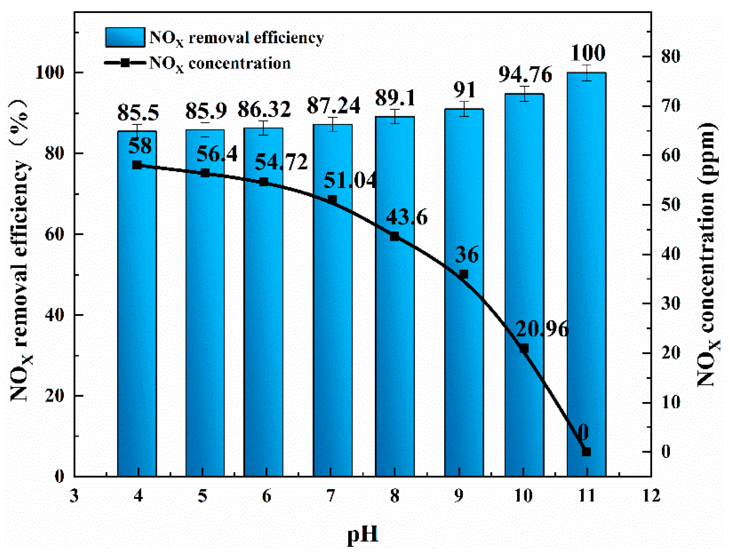
3.2. Effect of Initial pH Value on NOX Removal Efficiency

H2O2 is a weak acid, and it is too stable under strong acidic conditions, which reduce its oxidizing ability. In addition, under strong acidic conditions, due to the existence of equilibrium reactions, a large amount of H+ in the solution affects the reaction to the right, which is not conducive to the removal of NO, and NO2 and results in a decrease in the NOX removal efficiency. The reaction formula is as follows:
NO + NO2 + H2O↔H+ + NO2
OH·+ NO2→NO3 + H+
H2O2 + HNO2→NO3 + H+
Although the oxidizing ability of H2O2 is weak (standard electrode potential: 1.77 eV), the ·OH radicals generated by the decomposition of H2O2 have a strong oxidizing ability (standard electrode potential: 2.80 eV). The generated ·OH radicals can rapidly oxidize the NO to ensure that the NOX [46] can be effectively removed during the wet removal process. Thus, under alkaline conditions, a 1 mol/L NaOH solution should be used to adjust the pH of the removal solution, H2O2 and NaOH. The solution has a good removal effect for NO and NO2 acid gas. NaOH can accelerate the decomposition of H2O2, which generates ·OH radicals with a stronger oxidation effect and promotes the removal of NO by (NH2)2CO. The reactions of the NO in the alkaline (NH2)2CO and H2O2 removal solutions were as follows [10,46]:
H2O2 + OH↔H2O + HO2
NO + HO2→NO2 + OH
H2O2→2OH
OH + NO + OH→H2O + NO2
H2O2 + 2NO→2HNO2
NO + NO2 + H2O→2HNO2
3NO2 + H2O→2HNO3 + NO
2NO2 + H2O→HNO2 + HNO3
(NH2)2CO + 2HNO2→3H2O + 2N2 + CO2
The experimental conditions for the Type IV microchannel reactor were as follows: a reaction temperature of 20 °C and a gas-liquid flow rate of 150 mL/min. When the pH of the removal solution was 4, the NOX removal efficiency was 85.50%, and the concentration of the NOX was 58 ppm (Figure 5). As the pH of the removal solution gradually increased, when the pH value of the solution was 11, the NOX removal efficiency was 100%, and the NOX concentration in the exhaust gas was 0 ppm. The increase in the pH was conducive to Reactions (6), (7) and (9) in the removal solution; thus, the increase in the pH of the solution was conducive to the removal of NOX, and the removal efficiency was the highest (100%) when the pH was 11.

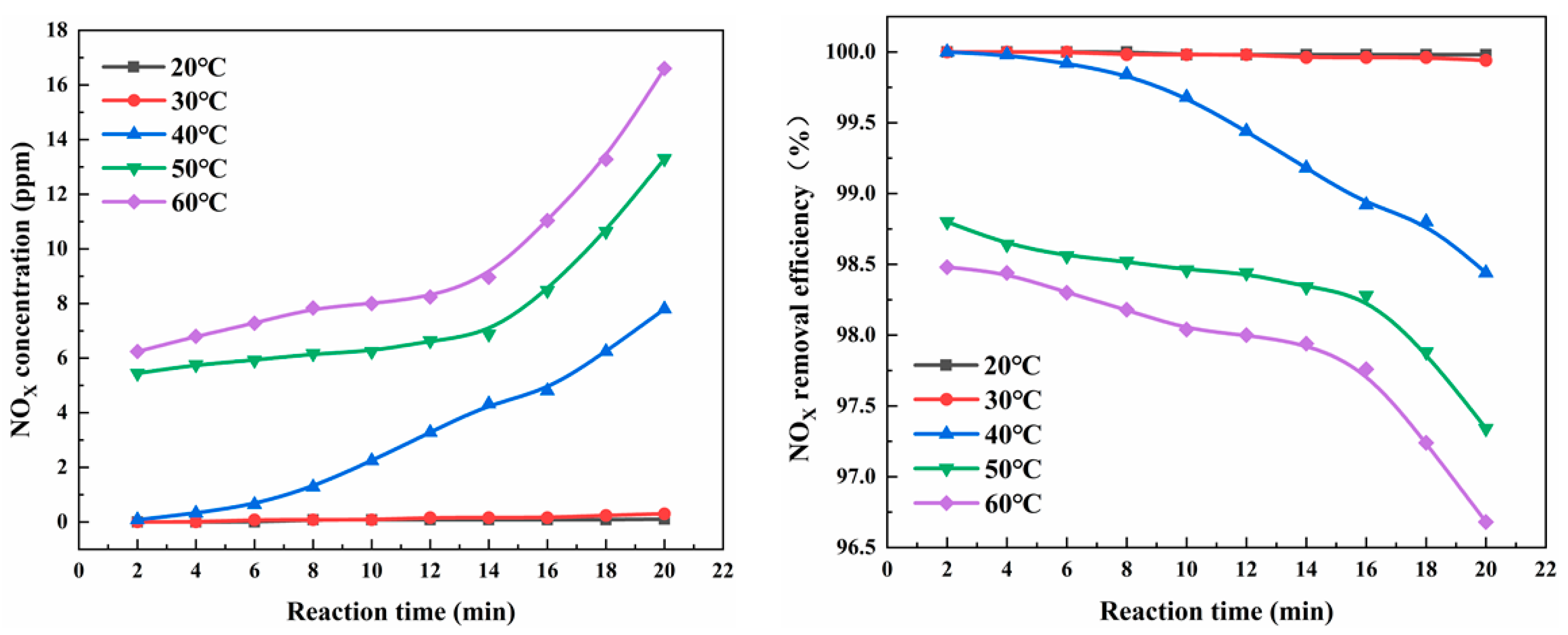
3.3. Effect of Solution Temperature on NOX Removal Efficiency

Under normal circumstances, the reaction rate of the chemical reaction increases with the increase in the reaction temperature; however, for a more complex reaction system, the increase in the temperature not only accelerates the progress of the main reaction, but it also accelerates the progress of the side reaction. For the gas-liquid two-phase reaction, the reaction is controlled by the gas and liquid phases, and the temperature requirements are different. Therefore, it is necessary to determine the appropriate temperature for the experiment. The experimental conditions for the Type IV microchannel were as follows: a solution pH of 10.26 and a gas-liquid flow of 150 mL/min. On the one hand, with the increase in the reaction temperature, more of the NO molecules became activated molecules, which increased the percentage of activated molecules, substantially increased the effective collision times of the molecules in the microchannel per unit time, accelerated the decomposition of H2O2, produced more hydrogen peroxide ions and promoted the removal of NO by (NH2)2CO (Figure 6). On the other hand, when the reaction temperature was higher than 50 °C, with the increase in the temperature, the solubility of the O2 and NOX in the solution decreased, and the reaction rate of the NO oxidation to NO2 in Reaction (9) decreased (Figure 6). In addition, high temperatures accelerated the decomposition of HNO2 and HNO3 and again released NO gas into the reaction system, which resulted in a decrease in the NOX removal efficiency [11].

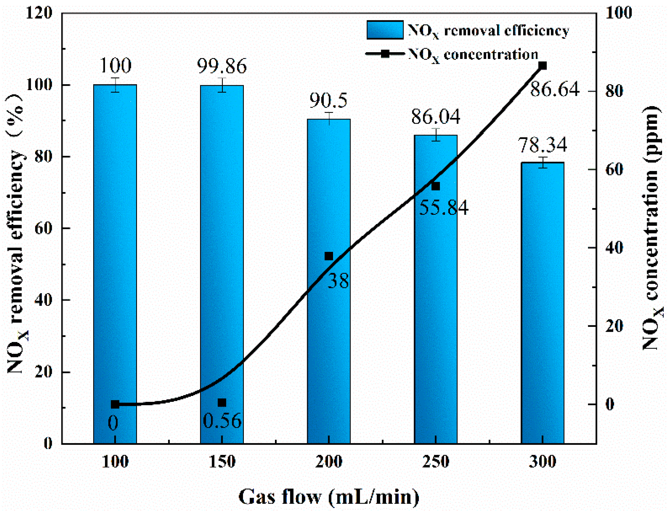
3.4. Influence of Inlet Flow on NOx Removal Efficiency

The actual contact area of the gas-liquid two-phase fluid in the microchannel in the microchannel reactor is affected by the change in the flow pattern of the mixed fluid, and the contact time (T) of the two-phase fluid in the microchannel reactor is determined by the flow rate; thus, the contact time (T) for the solution has as crucial effect on the NOx removal [47]. The longer the contact time between the gas and liquid phases in the micro-reaction channel, the greater the possibility of a reaction between the NO in the gas phase and the H2O2 and (NH2)2CO in the solution. The contact time (T) mentioned in Section 2.5 is regulated by the flow rate of the two phases entering the reactor, and the flow rate is regulated by a digital display stabilizer and convection pump. The experimental results are shown in Figure 7.
The experimental conditions for the Type IV microchannel reactor were as follows: a solution pH of 11, a gas flow and liquid flow of 1:1 and a reaction temperature of 20 °C. When the NO gas flow rate was 300 mL/min, the gas-liquid contact time was 3 s, the NOX removal efficiency was 78.34% and the NOX concentration was 86.64 ppm. With the decrease in the inlet flow rate, the gas-liquid contact time was 9 s, the NOX removal efficiency was 100% and the NOX concentration was 0 ppm. In the channels, the mass transfer between the gas and liquid phases can be carried out for a long time. Therefore, it was important to extend the length of the microchannel and study the effect of the residence time on the denitration efficiency.

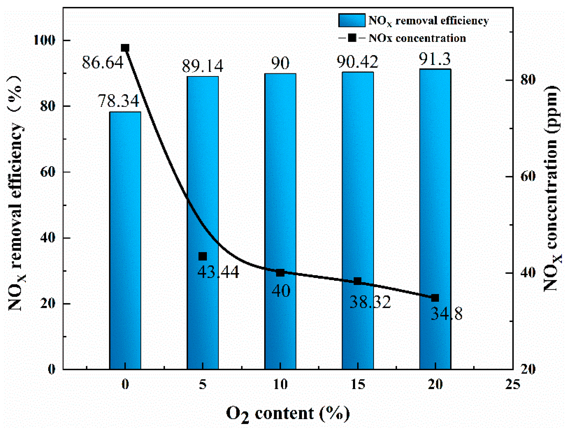
3.5. Influence of O2 Content in Flue Gas on NOX Removal Efficiency

The experimental conditions for the Type IV microchannel reactor were as follows: a solution pH of 11, a gas-liquid flow rate of 300 mL/min and a reaction temperature of 20 °C. The content of O2 is an important factor that affects the NOX removal efficiency. When there is O2 in the flue gas, the NO can react with it to generate a part of NO2, which offsets the inhibition of the H2O2 decomposition by O2 to generate hydrogen peroxide ion HO2 and OH· radicals. Digital flow stabilizer to adjust the O2 content in the simulated flue gas. The experimental results are shown in Figure 8. With the increase in the oxygen content, the NOX removal efficiency gradually increased. When the oxygen content was 20%, the NOX removal efficiency was the highest (91.30%) (NOX concentration: 34.8 ppm). When the oxygen content decreased, the NOX removal efficiency demonstrated a downward trend.

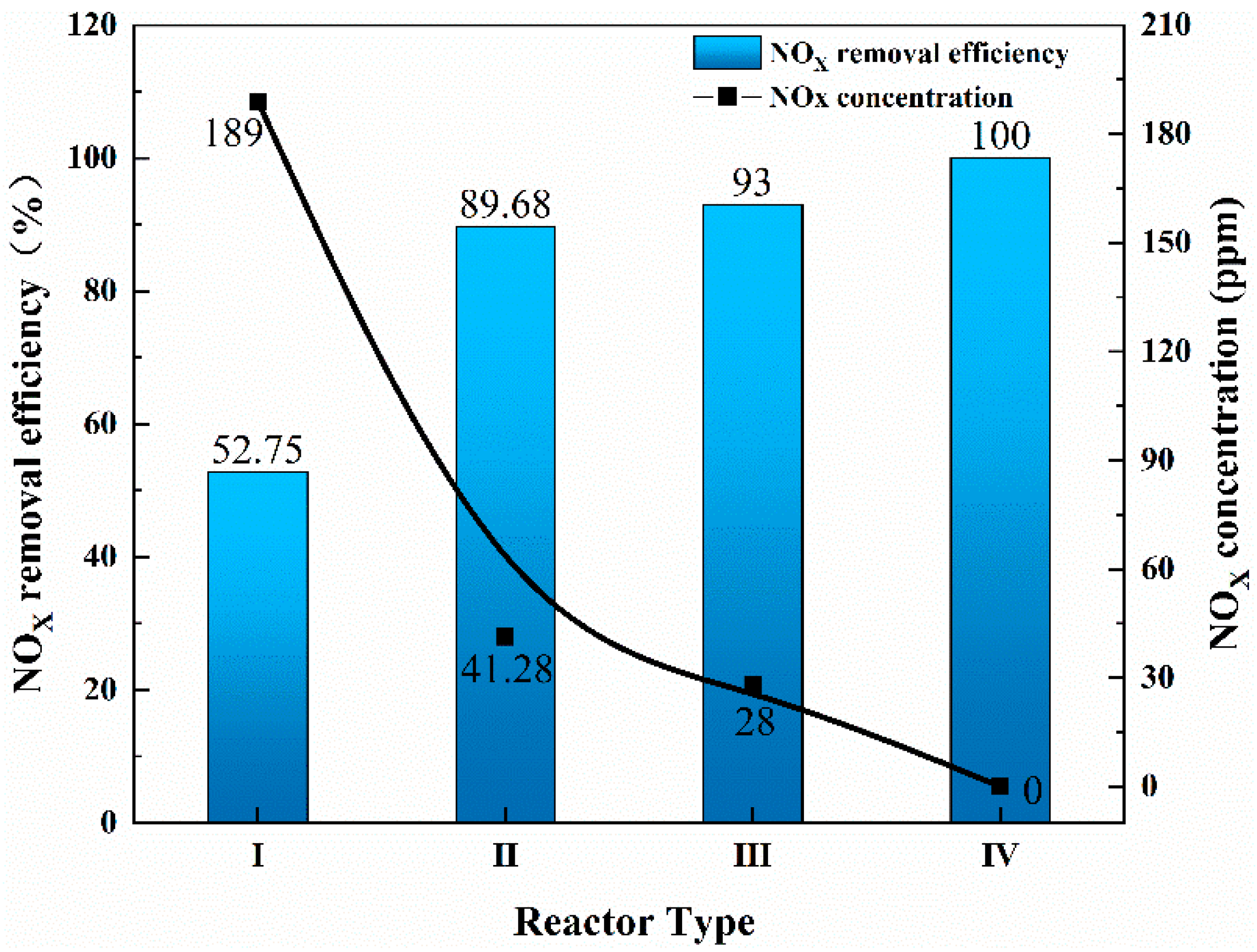
3.6. Effects of Different Types of Reactors on NOX Removal

For different microchannel reactors, the change in the structure size will also affect the NOX removal efficiency. The experimental conditions were a pH of 11, a gas-liquid flow rate of 100 mL/min and a reaction temperature of 20 °C. Compared with conventional bubbling reactors (NOX removal efficiency: 52.75%), the 3D-printed microchannel reactor achieved a higher removal efficiency (100%) and completely removed the NOX (Figure 9). Moreover, when the number of channels and the length of channels in the microchannel reactor increased, the removal efficiency of NOX was improved. The increase in the number of channels cut the fluid into smaller scales, and the increase in the length of the channels caused the gas-liquid two-phase contact time to increase, which made for more uniform mixing in the microchannel reactor and a more thorough reaction.

4. Conclusions

(1) Compared with the conventional reactors that are designed by traditional micromachining technology, the use of 3D printing to manufacture microchannel reactors is simple and convenient, and it allows us to effectively avoid the problems of the traditional manufacturing complexity, high processing costs and difficult promotion.
(2) When the NO concentration of the simulated flue gas was 400 ppm and the gas-liquid flow was 100 mL/min, a 500 mL mixed solution with H2O2 concentration of 0.5 mol/L and (NH2)2CO mass fraction of 3% was used. Under the experimental conditions of pH = 11, solution temperature of 20 °C and reaction time of 20 min, the best removal effect of NOX was achieved, and the removal efficiency was 100%. At the same time, when increasing the O2 content in the flue gas and the number and length of microchannels, the NOX removal efficiency will increase accordingly, which is conducive to the rapid and efficient reaction.
(3) For the prevention and control of nitrogen oxide pollution, a new solution is proposed, the combination of a microchannel reactor and wet denitration technology to remove nitrogen oxide, which saves energy and is more efficient, and which will play a greater role in environmental protection in the future.

Author Contributions

Conceptualization, S.J. and K.H.; Methodology, K.H.; Validation, K.H.; Formal Analysis, S.J., K.H., Y.Z.; Investigation, S.J.; Writing—Original Draft Preparation, K.H.; Writing—Review and Editing, K.H., S.J., Y.Z., X.W.; Supervision, J.Z., N.L., Y.G. All authors have read and agreed to the published version of the manuscript.

Funding

This study is supported by the National Natural Science Foundation of China (51964032).

Data Availability Statement

The data presented in this study are available on request from the corresponding author.

Conflicts of Interest

The authors declare no conflict of interest.

References

  1. Lei, D.; Chao, L.; Chen, K.; Huang, Y.; Diao, B. Atmospheric pollution reduction effect and regional predicament: An empirical analysis based on the Chinese provincial NOx emissions. J. Environ. Manag. 2017, 196, 178–187. [Google Scholar]
  2. Chen, L.; Liao, Y.; Xin, S.; Song, X.; Liu, G. Simultaneous removal of NO and volatile organic compounds (VOCs) by Ce/Mo doping-modified selective catalytic reduction (SCR) catalysts in denitrification zone of coal-fired flue gas. Fuel 2020, 262, 116485. [Google Scholar] [CrossRef]
  3. Liu, F.; Cai, M.; Liu, X.; Zhu, T.; Zou, Y. O3 oxidation combined with semi-dry method for simultaneous desulfurization and denitrification of sintering/pelletizing flue gas. J. Environ. Sci. 2021, 104, 253–263. [Google Scholar] [CrossRef] [PubMed]
  4. Wang, Z.; Lun, L.; Tan, Z.; Zhang, Y.; Li, Q. Simultaneous wet desulfurization and denitration by an oxidant absorbent of NaClO2/CaO2. Environ. Sci. Pollut. Res. 2019, 26, 29032–29040. [Google Scholar] [CrossRef] [PubMed]
  5. Song, L.; Yang, J.; Yu, S.; Xu, M.; Liang, Y.; Pan, X.; Yao, L. Ultra-high efficient hydrodynamic cavitation enhanced oxidation of nitric oxide with chlorine dioxide. Chem. Eng. J. 2019, 373, 767–779. [Google Scholar] [CrossRef]
  6. Wei, J.; Luo, Y.; Yu, P.; Cai, B.; Tan, H. Removal of NO from flue gas by wet scrubbing with NaClO2/(NH2)2CO solutions. J. Ind. Eng. Chem. 2009, 15, 16–22. [Google Scholar] [CrossRef]
  7. Adewuyi, Y.G.; Sakyi, N.Y.; Khan, M.A. Simultaneous removal of NO and SO2 from flue gas by combined heat and Fe2+ activated aqueous persulfate solutions. Chemosphere Environ. Toxicol. Risk Assess. 2018, 193, 1216–1225. [Google Scholar] [CrossRef]
  8. Hultén, A.; Nilsson, P.; Samuelsson, M.; Ajdari, S.; Normann, F.; Andersson, K. First evaluation of a multicomponent flue gas cleaning concept using chlorine dioxide gas—Experiments on chemistry and process performance. Fuel 2017, 210, 885–891. [Google Scholar] [CrossRef]
  9. Yan, J.; Zhou, F.; Ying, Z.; Wu, X.; Lu, H. Wet oxidation and absorption procedure for NOx mathContainer Loading Mathjax removal. Environ. Technol. Innov. 2018, 11, 41–48. [Google Scholar] [CrossRef]
  10. Wen, Z.; Huang, X.; Shen, H.; Ding, N.; Li, Y.; Xu, J. Quantum Chemical Study on the Reaction Mechanism of NO Removal by Urea Combined with Hydrogen Peroxide. Arab. J. Sci. Eng. 2020, 45, 543–550. [Google Scholar] [CrossRef]
  11. Fang, P.; Cen, C.; Tang, Z.; Zhong, P.; Chen, D.; Chen, Z. Simultaneous removal of SO2 and NOX by wet scrubbing using urea solution. Chem. Eng. J. 2011, 168, 52–59. [Google Scholar] [CrossRef]
  12. Guo, Q.; He, Y.; Sun, T.; Wang, Y.; Jia, J. Simultaneous removal of NOx and SO2 from flue gas using combined Na2SO3 assisted electrochemical reduction and direct electrochemical reduction. J. Hazard. Mater. 2014, 276, 371–376. [Google Scholar] [CrossRef]
  13. Zhang, D.; Ren, L.; Yao, Z.; Wan, X.; Lu, P.; Zhang, X. Removal of Nitrogen Oxide Based on Anammox through Fe(II)EDTA Absorption. Energy Fuels 2017, 31, 7247–7255. [Google Scholar] [CrossRef]
  14. Cheng, X.; Bi, X.T. A review of recent advances in selective catalytic NOx reduction reactor technologies. Particuology 2014, 16, 1–18. [Google Scholar] [CrossRef]
  15. Li, D.; Xiao, Z.; Aftab, T.B.; Xu, S. Flue Gas Denitration by Wet Oxidation Absorption Methods: Current Status and Development. Environ. Eng. Sci. 2018, 35, 1151–1164. [Google Scholar] [CrossRef]
  16. Falcone Miller, S.; Miller, B.G. 7-Advanced flue gas cleaning systems for sulfur oxides (SOx), nitrogen oxides (NOx) and mercury emissions control in power plants. In Advanced Power Plant Materials, Design and Technology; Roddy, D., Ed.; Woodhead Publishing: Cambridge, UK, 2010; pp. 187–216. [Google Scholar]
  17. Wang, Z.-P.; Wang, Z.-W.; Xu, K. Optimization of wet denitration by dual oxidant (H2O2/S2O82−) advanced oxidation process. Fuel Process. Technol. 2017, 156, 82–89. [Google Scholar] [CrossRef]
  18. Hardin, J.O.; Ober, T.J.; Valentine, A.D.; Lewis, J.A. 3D Printing: Microfluidic Printheads for Multimaterial 3D Printing of Viscoelastic Inks (Adv. Mater. 21/2015). Adv. Mater. 2015, 27, 3278. [Google Scholar] [CrossRef] [Green Version]
  19. Bhattacharjee, N.; Urrios, A.; Kang, S.; Folch, A. The upcoming 3D-printing revolution in microfluidics. Lab Chip 2016, 16, 1720–1742. [Google Scholar] [CrossRef] [Green Version]
  20. Waheed, S.; Cabot, J.M.; Macdonald, N.P.; Lewis, T.; Guijt, R.M.; Paull, B.; Breadmore, M.C. 3D printed microfluidic devices: Enablers and barriers. Lab Chip 2016, 16, 1993–2013. [Google Scholar] [CrossRef] [Green Version]
  21. Yang, L.; Dietrich, N.; Loubière, K.; Gourdon, C.; Hébrard, G. Visualization and characterization of gas-liquid mass transfer around a Taylor bubble right after the formation stage in microreactors. Chem. Eng. Sci. 2016, 143, 364–368. [Google Scholar] [CrossRef] [Green Version]
  22. Pohorecki, R.; Sobieszuk, P.; Kula, K.; Moniuk, W.; Zieliński, M.; Cygański, P.; Gawiński, P. Hydrodynamic regimes of gas-liquid flow in a microreactor channel. Chem. Eng. J. 2008, 135, S185–S190. [Google Scholar] [CrossRef]
  23. Zhu, C.; Guo, H.; Chu, C.; Fu, T.; Ma, Y. Gas-liquid distribution and mass transfer of CO2 absorption into sodium glycinate aqueous solution in parallel multi-channel microreactor. Int. J. Heat Mass Transf. 2020, 157, 119943. [Google Scholar] [CrossRef]
  24. Yang, L.; Xu, F.; Chen, G. Enhancement of gas-liquid mass transfer and mixing in zigzag microreactor under ultrasonic oscillation. Chem. Eng. Sci. 2022, 247, 117094. [Google Scholar] [CrossRef]
  25. Jang, S.; Vidyacharan, S.; Ramanjaneyulu, B.T.; Gyak, K.-W.; Kim, D.-P. Photocatalysis in a multi-capillary assembly microreactor: Toward up-scaling the synthesis of 2H-indazoles as drug scaffolds. React. Chem. Eng. 2019, 4, 1466–1471. [Google Scholar] [CrossRef]
  26. Ahn, G.-N.; Yu, T.; Lee, H.-J.; Gyak, K.-W.; Kang, J.-H.; You, D.; Kim, D.-P. A numbering-up metal microreactor for the high-throughput production of a commercial drug by copper catalysis. Lab Chip 2019, 19, 3535–3542. [Google Scholar] [CrossRef] [PubMed]
  27. Yim, S.J.; Ramanjaneyulu, B.T.; Vidyacharan, S.; Yang, Y.D.; Kang, I.S.; Kim, D.-P. Compact reaction-module on a pad for scalable flow-production of organophosphates as drug scaffolds. Lab Chip 2020, 20, 973–978. [Google Scholar] [CrossRef]
  28. Dong, Z.; Wen, Z.; Zhao, F.; Kuhn, S.; Noël, T. Scale-up of micro- and milli-reactors: An overview of strategies, design principles and applications. Chem. Eng. Sci. X 2021, 10, 100097. [Google Scholar] [CrossRef]
  29. Zhang, J.; Wang, K.; Teixeira, A.R.; Jensen, K.F.; Luo, G. Design and Scaling Up of Microchemical Systems: A Review. Annu. Rev. Chem. Biomol. Eng. 2017, 8, 285–305. [Google Scholar] [CrossRef]
  30. Wang, K.; Lu, Y.; Luo, G. Strategy for scaling-up of a microsieve dispersion reactor. Chem. Eng. Technol. 2014, 37, 2116–2122. [Google Scholar] [CrossRef]
  31. Hessel, V.; Ehrfeld, W.; Herweck, T.; Haverkamp, V.; Lutz, N. Gas/liquid microreactors: Hydrodynamics and mass transfer. In Proceedings of the 4th International Conference on Microreaction Technology, IMRET 4, Atlanta, GA, USA, 5–9 March 1999. [Google Scholar]
  32. Su, H.; Wang, S.; Niu, H.; Pan, L.; Wang, A.; Hu, Y. Mass transfer characteristics of H2S absorption from gaseous mixture into methyldiethanolamine solution in a T-junction microchannel. Sep. Purif. Technol. 2010, 72, 326–334. [Google Scholar] [CrossRef]
  33. Eskin, D.; Mostowfi, F. A model of a bubble train flow accompanied with mass transfer through a long microchannel. Int. J. Heat Fluid Flow 2012, 33, 147–155. [Google Scholar] [CrossRef]
  34. Pennemann, H.; Hessel, V.; Kost, H.J.; Löwe, H.; De Bellefon, C. Investigations on pulse broadening for catalyst screening in gas/liquid systems. AIChE J. 2004, 50, 1814–1823. [Google Scholar] [CrossRef]
  35. Chasanis, P.; Kehrmann, K.; Kern, J.; Zecirovic, R.; Grünewald, M.; Kenig, E.Y. Investigation of a microstructured high efficiency contactor. Chem. Eng. Process. Process Intensif. 2011, 50, 1244–1251. [Google Scholar] [CrossRef]
  36. Li, X.; Jiang, F.; Ravindra, A.V.; Zhou, J.; Zhou, A.; Le, T.; Peng, J.; Ju, S. Mixing processes in a 3D printed large-flow microstructured reactor: Finite element simulations and experimental study. Chem. Eng. J. 2019, 370, 295–304. [Google Scholar] [CrossRef]
  37. de Mas, N.; Günther, A.; Kraus, T.; Schmidt, M.A.; Jensen, K. Scaled-out multilayer gas–liquid microreactor with integrated velocimetry sensors. Ind. Eng. Chem. Res. 2005, 44, 8997–9013. [Google Scholar] [CrossRef]
  38. Link, D.; Anna, S.L.; Weitz, D.; Stone, H. Geometrically mediated breakup of drops in microfluidic devices. Phys. Rev. Lett. 2004, 92, 054503. [Google Scholar] [CrossRef] [Green Version]
  39. Kreutzer, M.T.; Bakker, J.J.; Kapteijn, F.; Moulijn, J.A.; Verheijen, P.J.T. Scaling-up multiphase monolith reactors: Linking residence time distribution and feed maldistribution. Ind. Eng. Chem. Res. 2005, 44, 4898–4913. [Google Scholar] [CrossRef]
  40. Kashid, M.N.; Gupta, A.; Renken, A.; Kiwi-Minsker, L.J.C.E.J. Numbering-up and mass transfer studies of liquid–liquid two-phase microstructured reactors. Chem. Eng. J. 2010, 158, 233–240. [Google Scholar] [CrossRef] [Green Version]
  41. Andersson, H.; van der Wijngaart, W.; Enoksson, P.; Stemme, G. Micromachined flow-through filter-chamber for chemical reactions on beads. Sens. Actuators B Chem. 2000, 67, 203–208. [Google Scholar] [CrossRef]
  42. Chiou, C.-H.; Lee, G.-B.; Hsu, H.-T.; Chen, P.-W.; Liao, P.-C. Micro devices integrated with microchannels and electrospray nozzles using PDMS casting techniques. Sens. Actuators B Chem. 2002, 86, 280–286. [Google Scholar] [CrossRef]
  43. Jiang, F.; Yin, S.; Zhang, L.; Peng, J.; Ju, S.; Miller, J.D.; Wang, X. Solvent extraction of Cu(II) from sulfate solutions containing Zn(II) and Fe(III) using an interdigital micromixer. Hydrometallurgy 2018, 177, 116–122. [Google Scholar] [CrossRef]
  44. Lasalle, A.; Roizard, C.; Midoux, N.; Bourret, P.; Dyens, P.J. Removal of nitrogen oxides (NOx) from flue gases using the urea acidic process: Kinetics of the chemical reaction of nitrous acid with urea. Ind. Eng. Chem. Res. 1992, 31, 777–780. [Google Scholar] [CrossRef]
  45. Ding, J.; Zhong, Q.; Zhang, S.; Song, F.; Bu, Y. Simultaneous removal of NOX and SO2 from coal-fired flue gas by catalytic oxidation-removal process with H2O2. Chem. Eng. J. 2014, 243, 176–182. [Google Scholar] [CrossRef]
  46. Liu, Y.; Zhang, J.; Sheng, C.; Zhang, Y.; Zhao, L.L. Simultaneous removal of NO and SO2 from coal-fired flue gas by UV/H2O2 advanced oxidation process. Chem. Eng. J. 2010, 162, 1006–1011. [Google Scholar] [CrossRef]
  47. Zhou, Y.; Zhang, J.; Baral, A.; Ju, S.; Gu, Y. High-efficiency absorption of low NOX concentration in metallurgical flue gas using a three dimensional printed large-flow microstructured reactor-ScienceDirect. Arab. J. Chem. 2022, 15, 103711. [Google Scholar] [CrossRef]
Figure 1. Structural design diagram of 3D-printed multichannel large-volume microchannel reactor: (a) reactor diagram; (b,c) reactor profiles.
Processes 11 00158 g001
Figure 2. Schematic diagram of experimental setup.
Processes 11 00158 g002
Figure 3. NOX removal efficiencies of urea with different concentrations.
Processes 11 00158 g003
Figure 4. Effects of H2O2 concentration on NOX removal efficiency.
Processes 11 00158 g004
Figure 5. Effects of different pH values on NOX removal efficiency.
Processes 11 00158 g005
Figure 6. Effects of solution temperature on NOX removal efficiency.
Processes 11 00158 g006
Figure 7. Effect of gas flow rate at inlet end on NOx removal efficiency.
Processes 11 00158 g007
Figure 8. Effects of O2 content in flue gas on NOX removal efficiency.
Processes 11 00158 g008
Figure 9. Effects of different types of reactors on NOX removal efficiency.
Processes 11 00158 g009
Disclaimer/Publisher’s Note: The statements, opinions and data contained in all publications are solely those of the individual author(s) and contributor(s) and not of MDPI and/or the editor(s). MDPI and/or the editor(s) disclaim responsibility for any injury to people or property resulting from any ideas, methods, instructions or products referred to in the content.

