Article

Assessment of Harmonic Mitigation in V/f Drive of Induction Motor Using an ANN-Based Hybrid Power Filter for a Wheat Flour Mill

by
Bhuvaneswari Krishnasamy
1,* and
Kavithamani Ashok
2
1
Department of Electrical and Electronics Engineering, Nachimuthu Polytechnic College, Tamilnadu 642003, India
2
Department of Electrical and Electronics Engineering, Coimbatore Institute of Technology, Tamilnadu 641014, India
*
Author to whom correspondence should be addressed.
Processes 2022, 10(6), 1191; https://doi.org/10.3390/pr10061191
Submission received: 16 May 2022 / Revised: 6 June 2022 / Accepted: 9 June 2022 / Published: 15 June 2022

Abstract

:
Voltage/frequency (V/f) drive of a three-phase induction motor plays a crucial role in a flour mill for energy saving. Wheat consumption in India is increasing day by day, which reached 105,000 metric ton (MT) in 2021. India’s high wheat consumption and production increase flour mills. Thus, energy efficiency in a flour mill is a must in the present situation. Hence, V/f drives are widely used in flour mills. Apart from the advantages of V/f drive, electronic circuits in a drive induce harmonics in a power system. Power quality plays a vital role in a modern power system. Harmonics by V/f drive increase the current consumption, causing increased losses, cable overheating, and motor overheating, which necessitates a filter for harmonic mitigation. In this paper, an artificial neural network controller-based hybrid power filter is proposed for harmonic mitigation. A hybrid power filter (HPF) is presented to overcome the problems and achieve the active and passive power filter’s benefits. Harmonic mitigation of the proposed hybrid power filter is compared with the passive and active filter-based drives. This paper analyzes harmonic mitigation for three-phase induction motors with V/f drive installed in a 300-ton/day wheat flour mill’s purifier fan. The performance of the suggested system is analyzed under various speeds in the aspects of harmonic mitigation, reduction in current consumption, and energy saving using various filters. The entire system is developed and analyzed using MATLAB/Simulink. Energy saving is increased by around 10.97 kWh per year by HPF by means of reducing harmonics and current consumption compared to an active power filter, while it is increased by around 28.16 kWh/year compared to a passive power filter. Along with the harmonic mitigation, energy saving is also validated for various filters under various speeds.

1. Introduction

Electricity cost is an important issue in flour mills because it is a huge cost, after the cost of raw materials and labor cost. Since profit margins are generally relatively low in the wheat processing industry, efficient management of energy consumption has become a vital parameter [
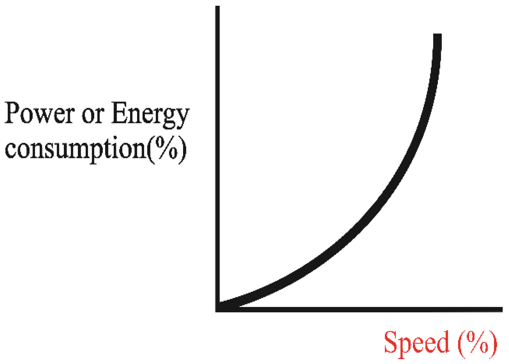
1]. By applying an energy-saving system to the fan of a flour mill, the entire consumption of energy can be reduced. In the flour mill, fans are used in the cleaning section and in the purifier. Among the total energy consumed by the flour mill, the cleaning system consumes 7.7% of the energy, while the purifier fan consumes 17.1% of the entire energy. Hence, by employing variable frequency drives (VFD) for fans in the cleaning section and purifier, significant energy can be saved, which reduces the electricity bill. If the VFD is used in a fan control application, savings of up to 50% are possible. The characteristics of speed and energy consumption of the squirrel cage induction motor is shown in Figure 1. This graph can be justified by an affinity law expressed in (1) [2]:
P o w e r 1 P o w e r 2 = ( R P M 1 R P M 2 ) 3
From the affinity law, it is clear that by reducing the speed of the motor, power consumption can be reduced. For example, a fan running at 80% speed consumes 50% of the energy compared to one running at full speed. Therefore, VFDs are widely used in flour mills for energy saving.
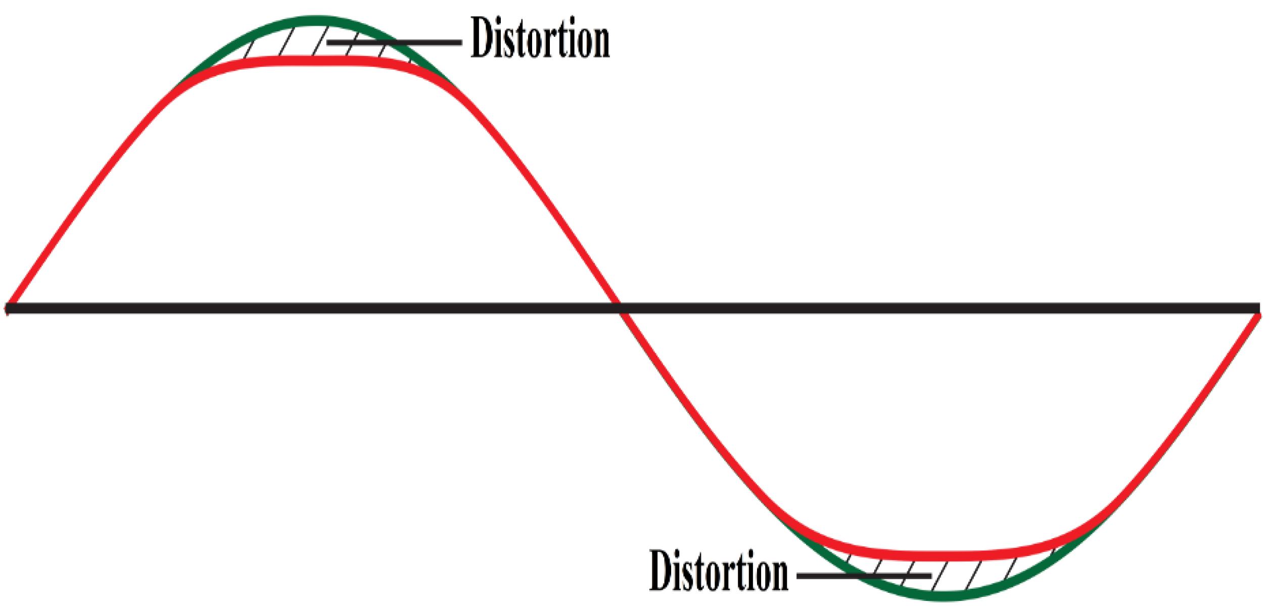
In VFD, the V/f ratio is maintained as constant to maintain the air-gap flux; thus, it is also called the V/f drive. The preliminary unit of a V/f drive produces oscillations in the AC line when the rectifier charges a capacitor unit in the DC bus. Current is consumed from the AC line just when the AC-DC converted voltage surpasses the level of voltage to which the capacitor is charged. Extreme harmonic distortion has many unfavorable impacts. Voltage distortion formed by VFD results in “flat-topping” of power system voltage waveforms, as shown in Figure 2, which in sequence causes the sensitive electronic components to malfunction [3].
The existence of harmonics in the power lines may result in increased power losses and overheating of motors and transformers connected in a line [4,5]. Thus, delivering a high-quality power to end users has become a vital problem for power engineers [6]. These effects, such as high losses and overheating of machines, lead to huge economic losses for industries that run 24/7. As flour mill runs continuously, to reduce energy cost, a V/f drive is employed, while power loss by the influence of harmonics may increase energy costs. In order to attain cost benefit and energy saving, harmonic mitigation is mandatory in V/f drive. Hence, in the V/f drive, a filter is necessary to reduce total harmonic distortion (THD) and to improve power quality.
A 6-pulse drive with an AC reactor, a 6-pulse drive with an input filter, a 12-pulse drive, an 18-pulse drive and a 24-pulse drive are various configurations of the V/f drive [7]. Among various methods, a 6-pulse VFD with an input filter and an 18-pulse VFD result in voltage and current THD within the IEEE-519 standard. In terms of THD as well as efficiency, the 6-pulse VFD with an input filter offers better results. Therefore, in this article, 6-pulse VFD with various types of input filters are proposed for harmonic mitigation and energy saving in flour mills.
Conventionally, passive filters are employed for minimizing the harmonics due to their easy design and vigorous nature. Passive filters with VFD in the maritime industry for fan and pump motors result in a total voltage harmonic distortion of less than 5% [8]. Yet, passive filters have the disadvantages of parallel and series resonance issues, and they are only able to filter frequencies for which a filter is designed; additionally, the filter is cumbersome in size, needing a huge area, and has a high cost. The passive filters’ disadvantages are compensated for by employing active filters, which depend on switch mode power converters, for controlling the abrogation of harmonics currents. Active filters insert recompensing current to eradicate harmonics in a non-linear load current. An active filter suppresses harmonics across the spectrum more effectively than a passive filter [
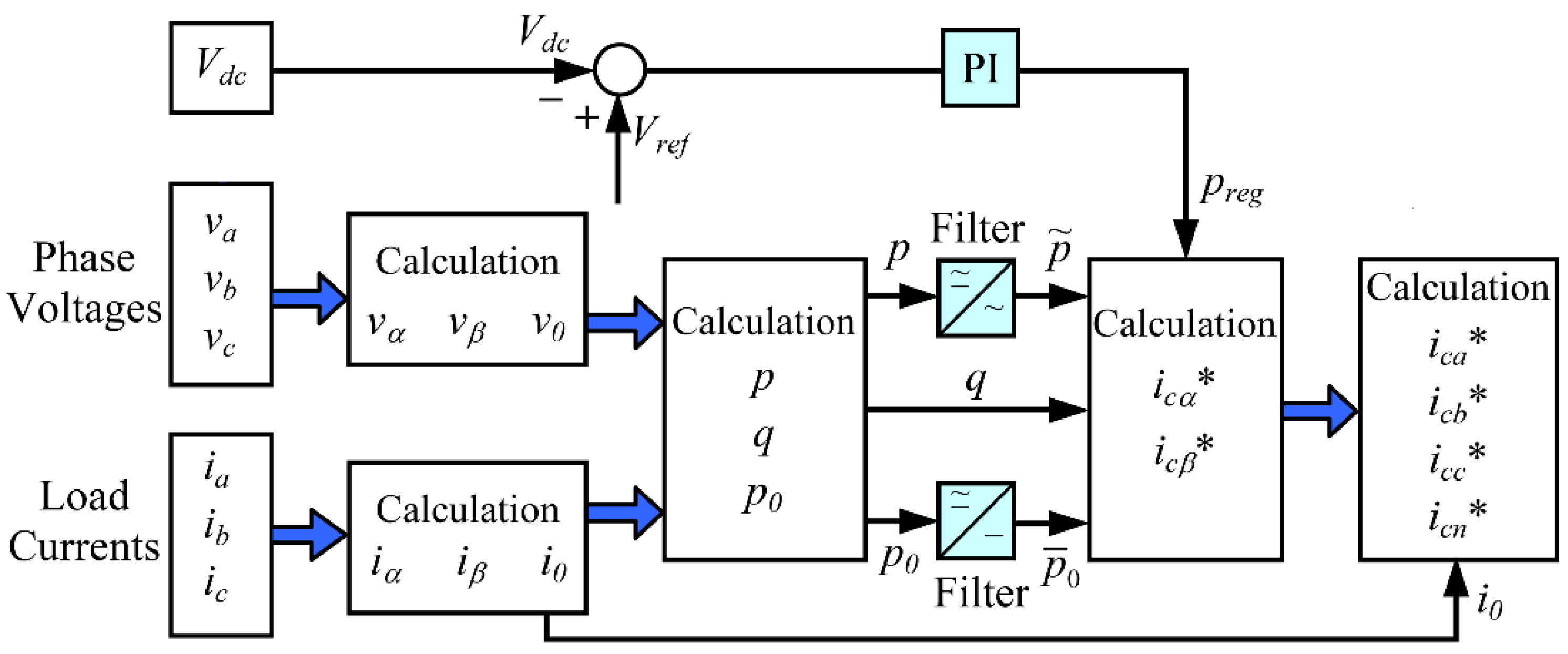
9]. In this paper, a shunt active power filter (SAPF) was used, utilizing modified instantaneous reactive power for reactive power compensation and current harmonic mitigation. Even though the essential benefits of enhanced filtering capability and low area necessity, the disadvantages related to it are the high-power rating, that the costs of installation are high and that the running costs are high [10]. The hybrid filter is a combination of an active and passive filter, which merges the benefits of both the filters, and requires a small power rating and minimal cost. Many researchers have investigated shunt active power filters for harmonic mitigation in VFD, whereas hybrid power filters are yet to be investigated. Hence, this article proposes a hybrid power filter for harmonic mitigation in VFD.
Instantaneous active and reactive power theory (p-q theory) and synchronous reference frame theory (SRF) (d-q theory) are two basic control techniques used in active power filters for harmonic detection in a power system [11,12]. In both methods, a PI controller is used for voltage regulation, while a hysteresis controller is employed for current control. A reference current is produced by the p-q theory or the SRF method [13,14]. Both methods are based on the time domain, so they are valid for both steady state and transient state operation in real time. A synchronizing system such as a phase locked loop is mandatory in the SRF method, in which the reference frame speed has to be constant [15]. However, due to harmonics in the voltage, speed is not maintained as constant. In [16], the comparative performance of both control methods was analyzed and found to be similar, but the p-q control method was more effective under transient conditions. At the same time, under balanced source voltage conditions, the memory required for p-q theory is significantly less than that required for the SRF method. Hence, in this article, the p-q control method is proposed for SAPF and HPF.
Many researchers analyzed innovative controllers, such as fuzzy logic controller (FLC), artificial neural network (ANN), sliding mode control and the gravitational search algorithm (GSA), tuned PI [17,18] for voltage regulation in order to improve performance, as the traditional PI controller fails under parametric variation situations. Among the many soft computing methods, ANN is proposed in this analysis due to its faster system response, decent performance with trained data, near resemblance to test data and system adaptability. ANN is designed with a bunch of neurons that have the ability of learning and adopting results in fast convergence and good dynamic response [19]. Hence, in this article, ANN is proposed with a hybrid power filter for voltage regulation using the modified p-q theory, to achieve maximum harmonic mitigation.
In this article, ANN-based HPF is proposed for V/f drive in flour mills for harmonic mitigation and energy saving. The effective performance of the proposed system in the aspect of harmonic reduction and energy saving is validated with the comparative analysis of V/f drive with passive power filter and PI controller-based shunt active power filter.

2. V/f Drive of Induction Motor

The V/f control technique maintains air-gap flux by managing stator voltage V and frequency f to keep the ratio V/f constant [20]. The synchronous speed Ns of a three-phase induction motor is expressed by:
N s = 120 ( f p )
where:
Ns = the synchronous speed in RPM;
p = the number of stator poles;
f = the supply frequency in Hertz.
The torque of the motor is directly proportional to the magnetic field of a stator. However, the voltage of stator is directly proportional to product of flux of stator and angular velocity. This led to the stator flux being proportional to the ratio of the voltage given and supply frequency. Therefore, the motor speed can be varied by changing the frequency. Thus, changing the frequency and voltage in the same ratio, the flux, and hence, torque are held as constant all over the speed range [21,22]. Figure 3 depicts the block illustration of the V/f drive of a three-phase induction motor.
In this analysis, a PI controller is applied to vary the frequency with respect to the reference speed, as shown in Figure 3. Z−1 is the unit that states the sampling time of speed feedback. Speed error between reference speed (ωRef) and actual speed (ω(k)) is handled through the PI controller, which decides frequency variation df (k). The df (k) is added with the existing frequency (f(k-1)) and acts as a reference/fundamental frequency (fRef) of the inverter. Meantime voltage is varied to keep the V/f ratio as constant as possible based on the newly developed frequency. The new frequency and voltage act as a reference for a three-phase pulse width modulation (PWM) inverter, which supplies a three-phase induction motor. Thus, with this method of control, the speed of the motor can be changed while the torque stays the same.

3. Passive Power Filter

Passive power filters (PPF) consist of tuned configuration of inductors, capacitors, and in some cases, resistors are utilized for eradicating particular harmonics (usually the 5th, 7th, etc.) [24]. They are incorporated either in parallel to eradicate harmonic currents of the line or to halt their movement amid system parts by adjusting the passive circuit components for creating resonance at a predefined chosen frequency [25]. It addition, it delivers reactive power compensation for the system; therefore, the power quality is improved. Based on the extenuation level, the passive power filters usage improves the overall price of installed drives by 200% to 500%. The topologies of shunt passive filters are single-tuned, double-tuned, first-order damped high-pass filter, second-order high-pass filter, third-order high-pass filter, and double bandpass filter. In this article, to minimize harmonics induced by V/f drive passive filters of single tuned passive filters, high-pass filters are employed.

4. Active Power Filters

Fundamentally, there are two kinds of active power filters (APF): the series and shunt type. Shunt Active Power Filters have been shown to be effective in current harmonic reduction. They are easy to implement and exhibit good performance in harmonic reduction. All power quality issues related to source current can be eliminated by Shunt Active Power Filters with suitable control [26].

4.1. Theory of Compensation

Figure 4 shows the basic theory of compensation using the Shunt Active Power Filter. In Figure 4, {a, b, c, N} is an indication of three phase and neutral, {isa, isb, isc, isn} is a source current, {ia, ib, ic, in} is a load current, {ica, icb, icc, isn} is a compensating current, {ica*, icb*,icc*,isn*} is a reference current, {va, vb, vc} is a source voltage, and Vdc is a DC link voltage.
The V/f drive of an induction motor acts as a load to the power source; a rectifier in a drive induces harmonics. The control of the SAPF is such that it will meet the complete reactive power needs of nonlinear loads so that the power factor at the source side is maintained at unity. There are various control methods to develop the reference current waveforms for the SAPF. Control that depends upon the modified p-q theory is one of the popular control methods, which is easy to implement and exhibits a satisfactory reduction in THD [28].

4.2. Modified p-q Theory

Instantaneous active and reactive power theory, popularly called the p-q theory control, was proposed by Agaki et al., in 1983 [26]. A control block illustration of p-q theory is depicted in Figure 5.
Based on this theory, compensation currents can be calculated such that the power at the source is always constant. An α β reference frame is formed for the grid voltages   (   v α ,   v β ) and load currents   (   i α ,   i β ) [29]:
[ v α v β ] = 2 3 [ 1 1 2 1 2 0 3 2 3 2 ] [ v a v b v c ]
[ i α i β ] = 2 3 [ 1 1 2 1 2 0 3 2 3 2 ] [ i a i b i c ]
Three-phase instantaneous real ( p ) and reactive power ( q ) can be calculated as in Equations (5) and (6) [29]:
p = v α i α + v β i β  
q = v α i β v β i α
where p and q are resolved into a mean value and an alternating value as expressed in Equations (7) and (8) [29]:
p = p ¯ + p ˜
q = q ¯ + q ˜
where p ¯ & q ¯ are formed by positive sequence segments of load current and p ¯ & q ¯ from the load current harmonic segments.
The distortion component of p and the whole q is given from the active power filter. Therefore, the needed compensating currents (   i c α ,   i c β ) is expressed as in Equation (9) [30]:
[ i c α i c β ] = [ v α v β v β v α ] 1 [ p ˜ q ]
These currents are converted back to a-b-c coordinates with the aid of inverse Clarke’s transform as in Equation (10) [30]:
[ i c a * i c b * i c c * ] = 2 3 [ 1 0 1 2 3 2 1 2 3 2 ] [ i c α i c β ]
This generated reference current is contrasted with calculated filter currents and the switching pulses are produced by utilizing a hysteresis band controller [30].
The practical presentation of a shunt active filter demands the voltage regulation at the inverter DC side (Vdc—the capacitor voltage), as illustrated in Figure 4, where reference value Vref is needed for the suitable operation of active filter inverter. DC voltage error is processed by a PI controller to produce p reg .
To enrich the shunt active power filter performance during non-ideal grid voltage conditions, the voltages taken for calculation of power should be free from distortions. The grid voltages are filtered with a low-pass filter. Before filtering, the voltages are converted into a synchronous reference frame for convenience in filtering out the unbalances in the voltages [30].
Transformation to the synchronous reference frame is given in Equation (11) [30]:
[ v d v q ] = [ c o s ϕ s i n ϕ s i n ϕ   c o s ϕ ] [ v α v β ]

5. Hybrid Power Filter

Figure 6 illustrates the hybrid power filter (HPF) arrangement for a three-phase three-wire system. By attaching an active filter in a shunt along with a passive filter, the HPF is constructed. The hybrid filter is linked to load in parallel and conquers the harmonics in current produced by a non-linear load. Every passive filter containing a tuned circuit consists of capacitor and inductor, attached to every phase of a three-phase system. The constraints of electrical resonance of tuned circuit of a passive filter are valuable in reducing harmonic orders equivalent to a specific frequency, thus giving a minimum impedance method for the harmonic currents to pass over the system that gives the load. A shunt active power filter typically contains power electronics converters, which are specifically made for injecting harmonics currents, equivalent in magnitude but conflicting in phase, to recompense non-linear load harmonics [31]. The filter controller depends on the modified instantaneous active and reactive power theory (the p-q theory) [32].
The control technique is conceptualized with the knowledge of giving the minimum impedance in the way of harmonic currents passing into the passive filter and high impedance to nominal frequency of 50 Hz. The technique supports in acquiring a minimum harmonic source current by forcing the harmonic currents passed via the passive filter. The modified p-q theory is effective in designing the controller present in active filter, as it assists the transformation of voltage and current from abc to dq0 coordinates, thus characterizing the instantaneous power on these coordinates [34].

ANN in Hybrid Power Filter

In this analysis, to enhance the power quality, the artificial neural network controller is proposed in active power filter section of a hybrid power filter. In an active power filter, the modified p-q theory is employed for harmonic reduction, in which DC voltage error is processed by a PI controller to control p reg . To enhance power quality, in this analysis, the artificial neural network controller is proposed to control p reg . The ANN is trained using the backpropagation algorithm of the Mean-Square-Error (MSE) amid the output and the expected output. In this analysis, the Levenberg-Marquardt method is employed to train the network, which trains the network with minimum time. ANN has self-learning capacity and a parallel computation structure. Neurons are trained to attain a minimum MSE by altering the weight value. In this article, the LMBP algorithm is proposed to tune the weights of neurons to achieve effective performance. The training set for the network is generated offline with the help of data attained from PI controller-based system. In this analysis, DC voltage error as input and PI controller output as target are applied for training ANN. In this research, to train ANN, 7230 samples were obtained to get an accurate output. Figure 7 illustrates a three-layer neural network, which is framed with the input layer, hidden layer and output layer.
The hidden layer is designed with sixteen neurons to achieve minimum processing time. ANN is employed in an active power filter section of HPF; the system converges training with MSE of 4.2 × 10⁻⁸ in 3.65 s with 141 epochs. This trained ANN is proposed in HPF to improve the power quality in the V/f drive.

6. Simulation Results and Analysis

In this analysis, three-phase induction motors in a purifier fan of a wheat flour mill with a capacity of 300 ton/day are controlled with the V/f technique. The purifier machine of 150 ton/day consists of four three-phase induction motors of 250 W. Since in this analysis, 300 ton/day mill is considered, eight motors of 0.25 kW are assumed for energy saving analysis. The motor is a 0.25 kW, three-phase squirrel cage induction motor, with 410 V and 50 Hz.

6.1. Performance Analysis of the V/f Drive with Various Filters

The speed control of the motor is analyzed under various speeds, to study the performance under various levels power and harmonics. The performance of the drive under different speeds with various filters are depicted with THD. A very short time harmonic measurement is adopted for THD analysis. As per IEEE standard 519-2014, 10 consecutive cycles are considered for THD measurement.
Case 1: A fan motor operating at 80% of its rated speed may result in a 50% energy savings, according to the affinity law; therefore, it is the first case of study. The machine is operated at a constant load of 0.6 Nm.
As per the affinity law expressed in Equation (1):
(250/Power2) = (1430/1144)3 Power2 = 128 W
which shows that a 20% reduction in speed reduces consumption by 50%. Thus, energy saving is attained with the help of the V/f drive. The performance of the drive along with the filters are presented in terms of source voltage, source current, speed, torque and THD. In the figures, one cycle is zoomed in on to show the shape of the voltage and current waves.
The performance of the drive using a passive filter is shown in Figure 8.
From Figure 8, it is observed that speed is maintained at 1144 RPM, while torque is maintained at 0.6 Nm. The load current shown in Figure 8e displays the noise in current due to power electronic circuit and nonlinear load. The effect of passive filter in removing harmonic distortion are shown in Figure 8a,b. Source voltage and current exhibit some distortion in wave shape, which shows deficiency of PPF. The PPF has a source current THD of 4.42% and a source current of 0.792 A in this case.
The performance of the drive using an active filter for case 1 is depicted in Figure 9.
From Figure 9, it can be noted that a load torque of 0.6 Nm is reached at 2 s, after which settling torque is maintained throughout the runtime. A reference speed of 1144 RPM is settled at 2 s and then sustained at the same speed. The influence of SAPF in the reduction in harmonics is displayed in the source voltage and current in Figure 9a,b. Compared to the wave shape by PPF, distortions are highly reduced by SAPF. Here, in SAPF, the source current THD is 2.11%, which is much less than the source current THD of PPF. The source current of PPF is 0.7778 A, whereas the source current of the SAPF is 0.792 A, which is 0.0142 A decreased compared to the PPF.
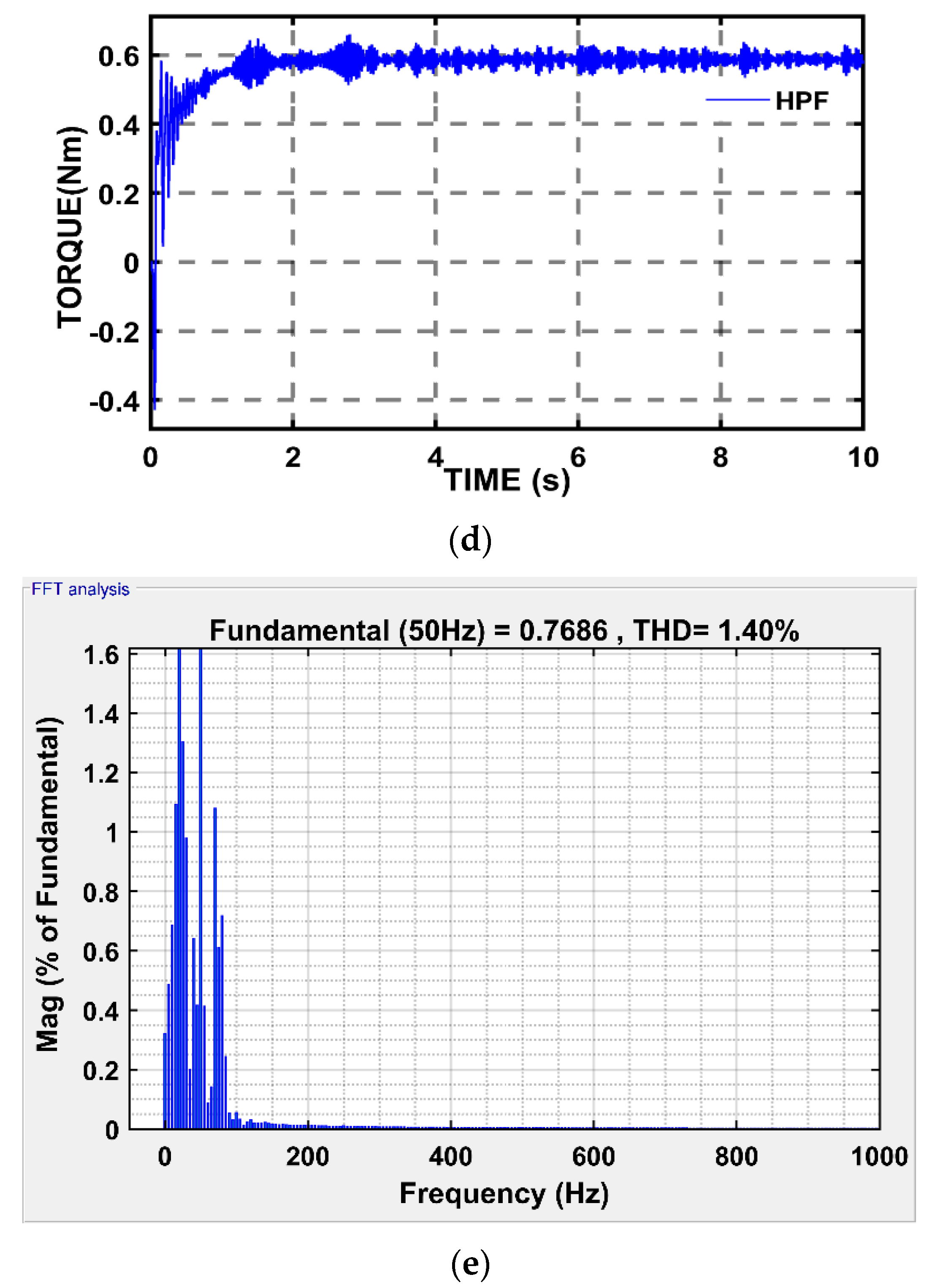
The performance of the drive using a hybrid power filter for case 1 is depicted in Figure 10.
As same as the above-mentioned analysis, during the time speed and torque are maintained constant. An effective filtering by HPF is displayed as the source voltage and current shape in Figure 10a,b. HPF has a source current THD of 1.40%, which is much lower than the filters mentioned above. The benefits of the combination of both filters are minimal harmonics. The source current is 0.7686 A, which is lower than both analyzed filters: 0.0092 A reduced compared SAPF and 0.0234 A reduced compared to PPF.
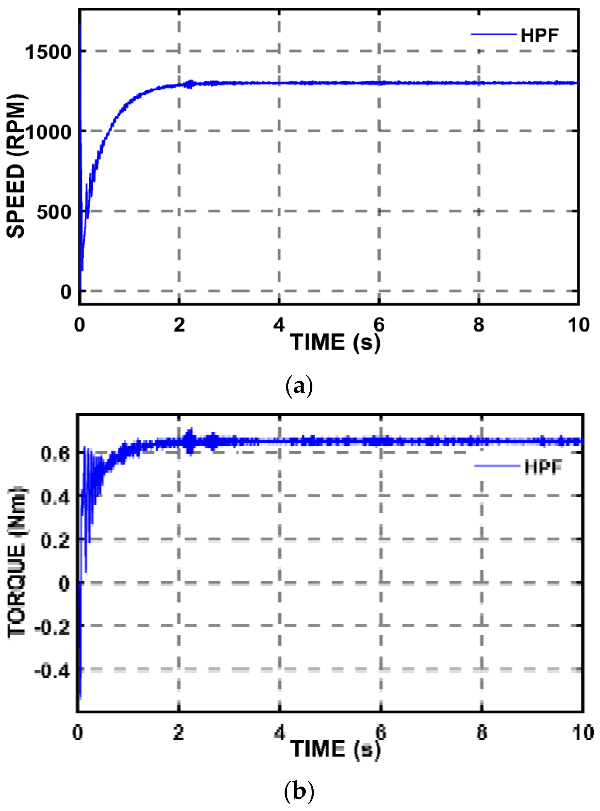
Case 2: In this case, the performance of the motor is analyzed at a speed of 1300 RPM for a torque of 0.6 Nm. As per the affinity law expressed in Equation (1), the power consumption at this speed is:
(250/Power2) = (1430/1300)3 Power2 = 187.83 W
From this calculation, it is observed that 25% of the power consumption causes a 10% reduction in speed. The speed and torque performance for case 2 are shown in Figure 11.
Figure 11 shows that the speed is maintained as a constant at 1300 RPM, with a torque of 0.6 Nm. Figure 10 and Figure 11 show the effective control of V/f drive under various speeds; the speed is constant for various reference speeds. The THD performance for case 2 using various filters is shown in Figure 12.
Figure 12 shows that in this case, the source current THD of SAPF and HPF filters are slightly less than the source current THD produced in Case 1. It can be clearly seen that the PPF has the highest source current THD among the filters, which is 4.79%, and the source current THD of SAPF is 2.04%. The HPF has the lowest percentage of THD of all the considered filters, which is just 1.39%.
The comparative performance of THD using various filters in both cases are presented in Table 1.
In Table 1, the comparative performance of various filters in the aspect of source current THD is given, which shows that every filter maintains THD within the IEEE standard. It is noted that the SAPF reduces more than 2.3% THD than PPF. Similarly, the HPF reduces around 0.8% THD than SAPF and 3% THD than PPF.

6.2. Result Discussion

In this analysis, harmonic mitigation in V/f drive is analyzed using various filters, which results in THD within the IEEE standard, whereas it was quite high at 61.65% without a filter, as seen in Figure 13.
This article compares the THD by SAPF in the V/f drive of the existing system to determine the effectiveness of the proposed hybrid power filter. In cement mills, a large number of V/f drive-based cooling fans are used, resulting in harmonics. In [35], SAPF was used to examine THD reduction in cement mills. Table 2 displays the comparative performance of the proposed ANN-based HAPF with the existing system [35].
From Table 2, it is observed that THD without a filter is almost equal in both existing and proposed systems at around 60%. The active filter produces a THD of 3.38%, while the ANN-based HPF reduces it to 1.40%. The comparative analysis presented in Table 1 and Table 2 reveals the effectiveness of ANN-based HPF in harmonic mitigation compared to other filters.

6.3. Influence of Filter in Reduction of Harmonic, Current Consumption and Copper Loss

Reduction in current consumption by various filters: Harmonic mitigation by various filters does not simply improve the waveshape of current; in the meantime, it reduces current consumption from the source. Table 3 shows the influence of each filter on current reduction under various speeds or various power levels from the simulation analysis.
Table 3 shows that the SAPF reduces 0.0183 A compared PPF. Proposed ANN-based HPF reduces current consumption by 0.0091 A compared to SAPF and 0.0274 A compared to PPF for case 2.
Energy saving by V/f drive: Wheat mill purifier of 300 ton/day runs eight motors for 24/7, so V/f is proposed for energy saving. Eight motors of 0.25 kW, each running 24/7 for one year, led to an energy consumption (E1) of:
E1 = 8 × 0.25 × 24 × 365 = 17,520 kWh
By employing the V/f drive, running machines at 80% speed may lead to an energy consumption (E2) of:
E2 = 8 × 0.128 × 24 × 365 = 8970 kWh
In the above expression, 0.128 kW is attained as per the affinity law stated in Equation (1). E2 is the energy consumed by employing the V/f drive, which is almost half of E1 without a drive. The machine running at 80% speed results in a power saving of 50%.
Reduction in copper loss by various filters: Influence of filters results in a reduction in THD, which improves the power quality. A reduction in THD reduces the current consumed. Moreover, a reduction in the current consumption reduces losses. The influence of each filter with regards to loss reduction for case 1 is described below.
Considering the copper loss of machine (PL) and that the stator resistance is 11 Ω, the copper loss of a machine using PPF, SAPF, and HPF is represented as PLPPF, PLSAPF and PLHPF, respectively.
PLPPF = 0.7922 × 11 = 6.9 W
Because wheat mill purifier is considered in this analysis, energy loss per year (EL/year) is estimated for eight motors as follows:
ELPPF/year= 8 × 24 × 6.9 × 365 = 483.55 kWh
Energy loss by copper loss of machines using PPF, SAPF and HPF are represented as ELPPF, ELSAPF and ELHPF, respectively. Loss by other filters is calculated similarly to PPF, as follows:
PLSAPF = 0.77782 × 11 = 6.6547 W ELSAPF/year = 8 × 24 × 6.6547 × 365 = 466.36 kWh PLHPF = 0.76862 × 11 = 6.4982 W ELHPF/year = 8 × 24 × 6.4982 × 365= 455.39 kWh
Energy saving by reducing copper loss by various filters is depicted in Table 4.
From this calculation, it is observed that energy loss is highly reduced with the help of the proposed HPF. Maximum copper loss of 483.55 kWh occurred using PPF, while it is reduced to 466.36 kWh with the aid of SAPF. SAPF reduces the energy loss by 17.19 kWh per year compared to PPF. HPF reduces energy loss by around 10.97 kWh per year compared to SAPF, and by 28.16 kWh compared to PPF. This power reduction is an additional benefit, along with the energy savings by the V/f drive as per the affinity law.
From the analysis, it is observed that a hybrid power filter with the V/f drive as a purifier in a wheat mill, along with energy saving, increases the power quality. A reduction in THD reduces the current consumption and losses compared to other filters, which reduces overheating of the motor and cables.

7. Conclusions

In this article, the V/f drive of a three-phase induction motor for purifier fans in a wheat mill with a capacity of 300 ton/day is analyzed. Power electronic circuits in the drive introduce harmonics into the power system, which necessitates a harmonic power filter. In this article, an enhanced hybrid power filter is proposed using a modified p-q theory with an ANN controller. An artificial neural network controller employs DC voltage regulation in shunt active filter sections to improve the performance of a hybrid filter. To validate the performance of proposed system, a passive filter and an active filter were also analyzed for the harmonic mitigation in the V/f drive. All filters are analyzed for the V/f drive under various speeds and loads. As per IEEE standard 519-2014, 10 consecutive cycles are considered for THD measurement, and all filters reduce harmonics within the IEEE standard under various speeds. Inclusion of a filter with the V/f drive not only reduces THD, it also reduces current consumption. A passive filter reduces THD by around 4.5% and valued copper loss by PPF is 483.55 kWh/year. The shunt active power filter with the modified p-q theory using a PI controller-based DC voltage control reduces THD by around 2% under both cases of speed, which is reduced by around 50% compared to a passive filter and results in a copper loss of 466.36 kWh/year. In both cases, THD, with the proposed ANN-based hybrid filter, is reduced to 1.4%, which is 70% less than the passive filter. The influence of harmonic mitigation by the proposed filter results in a reduction in the source current of around 0.0274 A compared to a passive filter. Since the wheat mill purifier runs 24/7, the reduction in source current by HPF reduces the energy loss by around 10.97 kWh per year compared to SAPF, and by 28.16 kWh compared to PPF. The energy saving by copper loss reduction is an added benefit along with the energy saving by the V/f drive as per the affinity law. From the analysis, it is observed that the proposed hybrid power filter with the V/f drive for the purifier in the wheat mill, along with energy saving, reduces THD more than other filters. In the future, the analysis may be extended to an advanced optimization algorithm.

Author Contributions

Conceptualization, B.K. and K.A.; methodology, B.K.; software, B.K.; validation, B.K.; formal analysis, B.K.; investigation, B.K.; writing—original draft preparation, B.K.; writing—review and editing, B.K. and K.A.; supervision, K.A. All authors have read and agreed to the published version of the manuscript.

Funding

This research received no external funding.

Institutional Review Board Statement

Not applicable.

Informed Consent Statement

Not applicable.

Data Availability Statement

Not applicable.

Conflicts of Interest

The authors declare no conflict of interest.

References

  1. Dharmarathna, S. Revolution of Grinding Mill (Roller Body) Design, Operation, Maintenance and Advancements. Available online: https://www.linkedin.com/pulse/revolution-grinding-mill-roller-body-design-operation-dharmarathna?trk=public_profile_article_view (accessed on 3 June 2019).
  2. Arun Shankar, V.K.; Subramaniam, U.; Padmanaban, S.; Holm-Nielsen, J.B.; Blaabjerg, F.; Paramasivam, S. Experimental investigation of power signatures for cavitation and water hammer in an industrial parallel pumping system. Energies 2019, 12, 1351. [Google Scholar] [CrossRef] [Green Version]
  3. Blanco, A.M.; Gupta, M.; Gil de Castro, A.; Rönnberg, S.; Meyer, J. Impact of flat-top voltage waveform distortion on harmonic current emission and summation of electronic household appliances. Renew. Energy Power Q. J. 2018, 1, 698–703. [Google Scholar] [CrossRef]
  4. Younis, S.A.; Al-Yousif, O.M. Electrical Power System Harmonics Analysis Using ETAP. Al-Rafidain Eng. J. (AREJ) 2022, 27, 90–98. [Google Scholar] [CrossRef]
  5. Carpinelli, G.; Iacovone, F.; Russo, A.; Varilone, P.; Verde, P. Analytical Modeling for Harmonic Analysis of Line Current of VSI-Fed Drives. IEEE Trans. Power Deliv. 2004, 19, 1212–1224. [Google Scholar] [CrossRef]
  6. Malik, H.; Fatema, N.; Iqbal, A. Intelligent Data Analytics for Power Quality Disturbance Diagnosis Using Extreme Learning Machine (ELM). In Intelligent Data-Analytics for Condition Monitoring, 1st ed.; Academic Press: London, UK, 2021; pp. 91–114. [Google Scholar]
  7. Hoevenaars, A.H.; Fahrney, M.; James, M.; McGraw, M. Design considerations when applying various ASD topologies to meet harmonic compliance. In Proceedings of the Record of Conference Papers Industry Applications Society 57th Annual Petroleum and Chemical Industry Conference (PCIC), San Antonio, TX, USA, 20–22 September 2010. [Google Scholar]
  8. Giannoutsos, S.V.; Manias, S.N. A systematic power-quality assessment and harmonic filter design methodology for variable-frequency drive application in marine vessels. IEEE Trans. Ind. Appl. 2015, 51, 1909–1919. [Google Scholar] [CrossRef]
  9. Hrubý, T.; Kocman, S.; Pečínka, P. Using active filter for harmonic mitigation in power grid of industry plant. In Proceedings of the 16th International Scientific Conference on Electric Power Engineering (EPE), Kouty nad Desnou, Czech Republic, 20–22 May 2015. [Google Scholar]
  10. Lin, B.-R.; Yang, B.-R.; Tsai, H.-R. Analysis and operation of hybrid active filter for harmonic elimination. Electric Power Syst. Res. 2002, 62, 191–200. [Google Scholar] [CrossRef]
  11. Hadi, A.M.; Thjeel, E.M.; Nahar, A.K. A Review of Control Technique Applied in Shunt Active Power Filter (SAPF). Eng. Tech. J. 2022, 40, 1–10. [Google Scholar] [CrossRef]
  12. Constantinescu, M.D.; Popescu, M.; Suru, C.V. Comparative Analysis of Two Methods of Calculating the Prescribed Current in a Shunt Active Filtering System. Ann. Univ. Craiova Electr. Eng. Ser. 2021, 45, 46–51. [Google Scholar] [CrossRef]
  13. Aiwa, F.F.; Alkhayyat, M.T.; Suliman, M.Y. A Review on PQ Theory Based Shunt Active Power Filter. Des. Eng. 2021, 6, 6919–6938. [Google Scholar]
  14. Babu, R.M.; Rao, M.V.G.; Rao, R.S. Battery Energy Integrated Active Power Filter for Harmonic Compensation and Active Power Injection. Sustain. Comput. Inform. Syst. 2022, 35, 100664. [Google Scholar]
  15. Hoon, Y.; Mohd Radzi, M.A.; Mohd Zainuri, M.A.A.; Zawawi, M.A.M. Shunt active power filter: A review on phase synchronization control techniques. Electronics 2019, 8, 791. [Google Scholar] [CrossRef] [Green Version]
  16. Madhushan Reddy, M.; Lenine, D. Power quality improvement using PQ and SRF algorithms in shunt active power filter (SAPF) with unbalanced source voltage. J. Mech. Cont. Math. Sci. 2020, 5, 40–57. [Google Scholar] [CrossRef]
  17. Agrawal, S.; Palwalia, D.K.; Kumar, M. Performance analysis of ANN based three-phase four-wire shunt active power filter for harmonic mitigation under distorted supply voltage conditions. IETE J. Res. 2019, 68, 1–9. [Google Scholar] [CrossRef]
  18. Kumar, P.; Mahajan, A. Soft computing techniques for the control of an active power filter. IEEE Trans. Power Deliv. 2008, 24, 452–461. [Google Scholar] [CrossRef]
  19. Tekwani, P.N.; Chandwani, A.; Sankar, S.; Gandhi, N.; Chauhan, S.K. Artificial neural network-based power quality compensator. Int. J. Power Electron. 2020, 11, 256–282. [Google Scholar] [CrossRef]
  20. Habbi, H.M.D.; Ajeel, H.J.; Ali, I.I. Speed control of induction motor using PI and V/F scalar vector controllers. Int. J. Comput. Appl. 2016, 151, 36–43. [Google Scholar]
  21. Chen, L.; Sun, X.; Jiang, H.; Xu, X. A high-performance control method of constant-controlled induction motor drives for electric vehicles. Math. Probl. Eng. 2014, 2014, 386174. [Google Scholar]
  22. Dems, M.; Komeza, K.; Szulakowski, J.; Kubiak, W. Increase the Efficiency of an Induction Motor Feed from Inverter for Low Frequencies by Combining Design and Control Improvements. Energies 2022, 15, 530. [Google Scholar] [CrossRef]
  23. Suetake, M.; da Silva, I.N.; Goedtel, A. Embedded DSP-based compact fuzzy system and its application for induction-motor V/f speed control. IEEE Trans. Ind. Electron. 2010, 58, 750–760. [Google Scholar] [CrossRef]
  24. Desai, S.S.; Dattesh, K.H.; Pillai, J. Design of shunt passive filter for reducing harmonic in variable frequency drives (VFDs): A Review. J. Emerg. Tech. Innovat. Res. 2019, 6, 178–183. [Google Scholar]
  25. Srivastava, K.K.; Shakil, S.; Pandey, A.V. Harmonics & its mitigation technique by passive shunt filter. Int. J. Soft Comput. Eng. 2013, 3, 325–331. [Google Scholar]
  26. Akagi, H.; Kanazawa, Y.; Nabae, A.A.H.; Kanazawa, Y.; Fugita, K.; Nabe, A. Generalised theory of instantaneous reactive power and its application. Electr. Eng. Jpn. 1983, 103, 483–490. [Google Scholar] [CrossRef]
  27. Afonso, J.L.; Pinto, J.G.; Gonçalves, H. Active power conditioners to mitigate power quality problems in industrial facilities. In Power Quality Issues, 1st ed.; Zobaa, A., Ed.; InTech: Houston, TX, USA, 2013; pp. 105–137. [Google Scholar]
  28. Chawla, P.; Lalwani, M. Analysis and simulation of reactive power theory for harmonic elimination using shunt active power filter. Int. J. Intell. Sustain. Comput. 2021, 1, 181–193. [Google Scholar]
  29. Amir, A.I.; Sreerama Kumar, R.; Yusuf, A.A.T. Modeling and Simulation of a PI Controlled Shunt Active Power Filter for Power Quality Enhancement Based on P-Q Theory. Electronics 2020, 9, 1–17. [Google Scholar]
  30. Kale, M.; Özdemir, E. Harmonic and reactive power compensation with shunt active power filter under non-ideal mains voltage. Electr. Power Syst. Res. 2005, 74, 363–370. [Google Scholar] [CrossRef]
  31. Panchbhai, A.; Parmar, S.; Prajapati, N. Shunt active filter for harmonic and reactive power compensation using pq theory. In Proceedings of the International Conference Power and Embedded Drive Control (ICPEDC), Chennai, India, 16–18 March 2017; IEEE: Piscataway, NJ, USA, 2017; pp. 260–264. [Google Scholar]
  32. Devassy, S.; Singh, B. Modified PQ-theory-based control of solar-PV-integrated UPQC-S. IEEE Trans. Ind. Appl. 2017, 53, 5031–5040. [Google Scholar] [CrossRef]
  33. Mishra, A.K.; Ray, P.K.; Mallick, R.K.; Mohanty, A.; Das, S.R. Adaptive fuzzy controlled hybrid shunt active power filter for power quality enhancement. Neural Comput. Appl. 2021, 33, 1435–1452. [Google Scholar] [CrossRef]
  34. Frifita, K.; Boussak, M. A novel strategy for high performance fault tolerant control of shunt active power filter. Electr. Eng. 2022, 1–11. [Google Scholar] [CrossRef]
  35. Kusumalatha, Y.; Obulesh, Y.P.; Saibabu, C. Harmonics Mitigation of Industrial Motor Drives with Active Power Filters in Cement Plant-A Case SStudy. Int. J. Power Electr. Drive Syst. 2012, 2, 1–8. [Google Scholar]
Figure 1. Characteristics of speed and energy consumption of a squirrel cage induction motor [2].
Processes 10 01191 g001
Figure 2. “Flat-topped” power-system voltage waveform [3].
Processes 10 01191 g002
Figure 3. Block illustration of the V/f drive of three-phase induction motor [23].
Processes 10 01191 g003
Figure 4. Shunt active power filter [27].
Processes 10 01191 g004
Figure 5. Control block illustration of the p-q theory [27].
Processes 10 01191 g005
Figure 6. The schematic of HPF [33].
Processes 10 01191 g006
Figure 7. Structure of the neural network.
Processes 10 01191 g007
Figure 8. The performance of the drive using a passive filter for case 1. (a) Source voltage. (b) Source current. (c) Speed. (d) Torque. (e) Load current. (f) THD of a source current.
Processes 10 01191 g008aProcesses 10 01191 g008b
Figure 9. The performance of the drive using an active filter for case 1. (a) Source voltage. (b) Source current. (c) Speed. (d) Torque. (e) THD of source current.
Processes 10 01191 g009aProcesses 10 01191 g009b
Figure 10. The performance of the drive using a hybrid power filter for case 1. (a) Source voltage. (b) Source current. (c) Speed. (d) Torque. (e) THD of source current.
Processes 10 01191 g010aProcesses 10 01191 g010b
Figure 11. Speed and torque performance for case 2. (a) Speed. (b) Torque.
Processes 10 01191 g011
Figure 12. THD performance for case 2 using various filters. (a) Passive Power Filter. (b) Active Power filter. (c) Hybrid Power Filter.
Processes 10 01191 g012aProcesses 10 01191 g012b
Figure 13. THD performance of the current without a filter.
Processes 10 01191 g013
Table 1. Comparative performance of THD using various filters.
Type of FilterTHD (%)
Case 1Case 2
Passive4.424.79
Active2.112.04
Hybrid1.401.39
Table 2. Comparative performance of the current using various filters.
SystemWithout Filter THD (%)Type of FilterWith Filter THD (%)
Existing [35]60.4%Active [35]3.38
Proposed61.65%ANN-HPF1.40
Table 3. Comparative performance of the current using various filters.
Type of FilterCurrent (A)
Case 1Case 2
Passive0.7920.796
Active0.77780.7777
Hybrid0.76860.7686
Table 4. Energy saving by reducing copper loss by various filters.
Type of FilterCopper Loss/Year (kWh)Energy Saved/Year Compared to PPF (kWh)
Passive483.55-
Active466.3617.19
Hybrid455.3928.16
Publisher’s Note: MDPI stays neutral with regard to jurisdictional claims in published maps and institutional affiliations.

