Article

Catalytic Properties of Free-Base Porphyrin Modified Graphite Electrodes for Electrochemical Water Splitting in Alkaline Medium

by
Bogdan-Ovidiu Taranu
1 and
Eugenia Fagadar-Cosma
2,*
1
National Institute for Research and Development in Electrochemistry and Condensed Matter, Dr. A. Paunescu Podeanu Street No. 144, 300569 Timisoara, Romania
2
Institute of Chemistry “Coriolan Dragulescu”, Mihai Viteazu Ave. 24, 300223 Timisoara, Romania
*
Author to whom correspondence should be addressed.
Processes 2022, 10(3), 611; https://doi.org/10.3390/pr10030611
Submission received: 2 March 2022 / Revised: 10 March 2022 / Accepted: 17 March 2022 / Published: 21 March 2022
(This article belongs to the Special Issue From Small Molecules to High-Value Chemicals: Theory and Practice)

Abstract

:
Hydrogen generation via electrochemical water splitting is considered an eco-friendly pathway for obtaining this desired alternative energy source, and it has triggered an intensive search for low cost and efficient catalysts. Within this context, four free-base porphyrins were studied as heterogeneous catalysts for the oxygen and hydrogen evolution reactions (OER and HER) in alkaline aqueous solutions. TEM and STEM analyses of samples obtained by drop-casting the porphyrins from different organic solvents on TEM grids revealed a rich variety of aggregates due to the self-assembling property of the porphyrin molecules. Modified electrodes were manufactured by applying the four tetrapyrrolic macrocycles from various solvents on the surface of graphite supports, in one or more layers. Experiments performed in 0.1 M and 1 M KOH electrolyte solutions allowed the identification of the most electrocatalytically active electrodes for the OER and HER, respectively. In the first case, the electrode was manufactured by applying three layers of 5-(4-pyridyl)-10,15,20-tris(4-phenoxyphenyl)porphyrin on the graphite substrate from N,N-dimethylformamide solution was identified as overall catalytically superior. In the second case, the electrode obtained by applying one layer of 5,10,15,20-tetrakis(4-allyloxyphenyl)-porphyrin from benzonitrile solution displayed an HER overpotential value of 500 mV at i = −10 mA/cm2 and a Tafel slope of 190 mV/dec.

Graphical Abstract

1. Introduction

Fossil fuels are currently the most widely used energy source [1]. While they are cheap due to the established infrastructure, they are also problematic given the fact that the energy demand keeps increasing and fossil fuels are non-renewable and rapidly depleting. Furthermore, their conversion process negatively impacts the environment through the resulting greenhouse gas emissions. In order to address these issues, researchers are looking for renewable and environmentally friendly solutions, with hydrogen being a very appealing alternative to traditional fuels due to its environmental benignity and reusability [2], and because it holds the promise for efficient energy production and storage [3]. In terms of the technology that can be used to generate H2, electrocatalytic water splitting is regarded as a clean, eco-friendly and sustainable strategy [4,5] that allows integration with other types of reusable energy, such as solar and wind power [6,7], and has the further advantage of relying on water, an abundant source for the production of the specified gas [8]. The two half-cell reactions that occur during the electrocatalytic water splitting are the O2 and H2 evolution reactions (OER and HER), responsible for the decomposition of water into its elements [9]. The OER unfolds at the anode and is considered to be the bottleneck reaction in the system thermodynamically and kinetically because it takes place through a multistep proton-coupled electron transfer (PCET), involving 4e and 4H+ [10,11]. The HER occurs at the cathode and, unlike the OER, it involves two electron transfers that ensure faster reaction kinetics [11]. Efficient and stable catalysts are required in order to increase the kinetics of the two half-cell reactions by lowering the energy barrier that must be overcome for their unfolding. The most active electrocatalysts for the OER are RuO2 and IrO2 [12,13], while for the HER, it is the Pt-based ones that are regarded the most efficient [14]. However, even though these catalysts significantly decrease the values of the O2 and H2 evolution overpotential, enhancing the energy conversion efficiency, they are nonetheless based on noble and rare metals belonging to a restricted platinum metal group (PMG). The scientific literature contains numerous studies in which the OER and HER properties of various electrocatalysts are investigated in order to identify those that can replace the rare and expensive materials with cheap earth-abundant ones, and that are also active and robust. Most compounds identified as having catalytic activity are metal-based, but there are some metal-free ones as well [15,16,17,18,19,20]. The search for new catalysts relevant for the water-splitting field has led to the identification of homogeneous and heterogeneous systems based on organic molecules, such as free-base porphyrins and their metallated analogues [3,21,22,23].
Porphyrins are a class of macrocyclic aromatic compounds that have in common the porphin macrocycle, constituting of four pyrrole units interconnected at the α position by methine bridges. Besides the fact that the macrocycle can bind almost any known metal ion, it can also be substituted with different functional moieties [21,24]. This latter characteristic recommends porphyrins as highly adequate for investigations regarding the interrelation between their structure and their properties, including their OER and HER electrocatalytic behavior. Furthermore, porphyrin molecules have the ability to self-assemble, forming porphyrin aggregates, as well as to co-assemble with other molecular species [21,25]. Self-assembly is a process in which molecules associate spontaneously through non-covalent interactions, resulting in structures that are both stable and well-defined [26]. Investigations regarding the obtaining and characterization of porphyrin assemblies reveal that the specified process is non-destructive with respect to the chemical structures of the molecules and the supports and can unfold in solution or at interfaces (e.g., solid support/solution and solution/air), leading to aggregates with properties often different, but more desirable, from those of the constituent molecules that are dependent on experimental conditions [27,28,29,30,31]. Porphyrin molecular self-assembly leads to the generation of two types of aggregates: the J-type, or the side-by-side arrangement, and the H-type, or the face-to-face arrangement. Besides, when porphyrin solutions are applied on solid substrates, these aggregates can further organize and give rise to complex structures, with various morphologies influenced not only by the intermolecular interactions but also by the surface properties of the supports [32]. The importance of the porphyrin self-assembly process for the water-splitting field is reflected in publications such as that of Seo et al. [33], which describes the obtaining of porphyrin formations on graphene support that provide catalytically active sites for the HER and enhance the charge transfer at the electrolyte/electrode interface.
Based on data reported in the scientific literature, the majority of studies concerning porphyrin-based catalysts for water-splitting have been focused on metalloporphyrins, while only a small number make use of free-base porphyrins [25,33,34,35,36,37]. Within this context, the current work presents an investigation regarding the OER and HER electrocatalytic properties of four metal-free porphyrin structures, namely, 5-(4-pyridyl)-10,15,20-tris(4-phenoxyphenyl)-porphyrin, 5,10,15,20-tetrakis(4-methoxyphenyl)-porphyrin, 5,10,15,20-tetrakis(4-allyloxyphenyl)-porphyrin and 5,10,15,20-tetrakis(p-tolyl)-porphyrin. These macrocycles have been the subject of several studies by Fagadar et al [28,32,38,39,40,41,42,43,44,45,46,47,48,49,50], but the researchers did not evaluate their electrocatalytic properties for the two half-reactions of water-splitting. Herein, these porphyrin species are analyzed in terms of their catalytic performance for the OER and HER in alkaline aqueous solutions after being drop-casted from different organic solvents on the surface of graphite supports in one, two or three layers. The experimental data show that in a strong alkaline medium the electrode modified by applying three layers of 5-(4-pyridyl)-10,15,20-tris(4-phenoxyphenyl)-porphyrin from N,N-dimethylformamide solution on the conductive substrate possesses superior OER catalytic properties, while the electrode obtained by depositing one layer of 5,10,15,20-tetrakis(4-allyloxyphenyl)-porphyrin from benzonitrile solution on the support displays an HER overpotential value of 500 mV at i = −10 mA/cm2 and a Tafel slope of 190 mV/dec. To the best of our knowledge, this is an innovative approach and the four free-base porphyrins have not been studied in terms of their OER and HER electrocatalytic properties in a strong alkaline medium.

2. Materials and Methods

2.1. Materials and Reagents

The four porphyrins, one of A3B type and three symmetrical ones, having the chemical structures presented in Scheme S1 from the Supplementary Data File (SDF), were synthesized and characterized in accordance with previously published procedures: 5-(4-pyridyl)-10,15,20-tris(4-phenoxyphenyl)porphyrin (P1) [28], 5,10,15,20-tetrakis(4-methoxy-phenyl)porphyrin (P2) [51], 5,10,15,20-tetrakis(4-allyloxyphenyl)-porphyrin (P3) [40] and 5,10,15,20-tetrakis(p-tolyl)porphyrin (P4) [52]. The solvents used to obtain the porphyrin solutions are: N,N-dimethylformamide (DMF), dichloromethane (DCM) and tetrahydrofuran (THF) from Sigma Aldrich, and benzonitrile (BN) from Merck. Other reagents used in the experiments are potassium hydroxide and potassium nitrate from Merck, potassium hexacyanoferrate(III) from Sigma Aldrich, ethanol from Honeywell and acetone from Chimreactiv (Bucharest). The chemicals used in the study are reagent grade and were employed without further purification. Aqueous solutions were prepared with laboratory-produced double-distilled water. The conductive support for the manufacturing of electrodes was rod-shaped spectroscopic graphite (type SW.114) from “Kablo Bratislava”, National Corporation “Electrocarbon Topolcany” Factory, Slovakia.

2.2. Working Electrodes Preparation

Graphite rods (⌀ = 6 mm) were inserted into PE tubes and subsequently exposed to a thermal treatment at 180 °C until the tubes became sealed to them. The surface of one end of the rods was modified with each of the four porphyrins and, during the experiments, was immersed into the electrolyte solution. The other end was connected to the potentiostat. Prior to modification, the surface of the graphite supports was polished using silicon carbide paper with different grit sizes (800 and 1200) and felt. This procedure was followed by thorough washing with double-distilled water, ethanol and acetone, a drying step at room temperature and, finally, the porphyrin modification stage. For the latter purpose, amounts of each porphyrin species were added to organic solvents with different polarities so as to obtain 0.15 mM porphyrin solutions. The order of increasing solvent polarity is DCM < THF < BN < DMF [53]. The solutions were ultrasonicated for 40 min and volumes of 10 µL were collected from them in order to modify the graphite supports via the drop-casting method. Some substrates were modified with one porphyrin layer, obtained by applying on their surface a 10 µL volume of porphyrin solution, followed by drying at 40 °C for 4 h and at room temperature for 20 h. Other substrates were modified with two and three layers, respectively, with the described treatment being employed for each coat. The resulted electrodes were coded as shown in Table 1.

2.3. Electrochemical Experiments

The porphyrin modified graphite electrodes, together with an unmodified graphite electrode (denoted G0), were employed as working electrodes (Sgeom = 0.28 cm2) in the electrochemical setup used to study their electrocatalytic properties for the OER and the HER in alkaline medium. The ensemble consisted of a Voltalab PGZ 402 potentiostat (Radiometer Analytical) connected to three electrodes and a glass cell. The counter electrode was a Pt plate (Sgeom = 0.8 cm2) and the Ag/AgCl (sat. KCl) electrode was utilized as reference. The electrocatalytic properties of the electrodes were investigated in 0.1 M KOH (pH = 13) and in 1 M KOH (pH = 14) electrolyte solutions. The iR-corrected linear sweep voltammograms (LSVs) were traced at a scan rate (v) of 1 mV/s for the OER studies, and of 5 mV/s for the HER test values selected based on literature data [54]. Nitrogen was used prior to each HER experiment to deoxygenate the electrolyte solution by bubbling for 10 min.
Unless otherwise specified, the electrochemical potential (E) values are represented versus the reversible hydrogen electrode (RHE) and the current density (i) values refer to the geometric current density. The electroactive surface area (EASA) of the most catalytically performant electrodes was estimated with the Randles–Sevcik equation [55,56] and the data obtained by recording cyclic voltammograms at different scan rates in 1 M KNO3 electrolyte solution, in the absence and in the presence of 4 mM K3[Fe(CN)6]. The experiments required for calculating the EASA and the diffusion coefficient of ferricyanide ions were performed in duplicate, using different electrodes, and the results are provided with the standard deviation. The equations employed to express the E values vs. RHE to calculate the O2 and H2 evolution overpotential (ηO2 and ηH2) values so as to determine the Tafel slope values and estimate the EASA [18,57,58,59] are presented in the Supplementary Data File (SDF) as Equations (S1)–(S5).

2.4. Physical-Chemical Characterizations

Transmission electron microscopy (TEM) and scanning transmission electron microscopy (STEM) images were obtained with a Titan G2 80-200 TEM/STEM microscope (FEI Company, Eidnhoven, The Netherlands) at 80 or 200 KV acceleration voltage using Digital Micrograph and TEM Imaging and Analysis software. The TEM bright field and STEM high-angle annular dark field modes were employed to record the TEM and STEM pictures, respectively. The specimens were prepared by drop-casting a volume of 3 µL from each porphyrin solution on TEM copper grids covered with continuous and amorphous carbon film, followed by drying at room temperature.
Scanning electron microscopy (SEM) images were recorded on the most catalytically performant modified electrodes outlined during the HER and OER investigations, using an Inspect S scanning electron microscope (FEI Company, The Netherlands) operated in high vacuum mode. Raman spectroscopy was employed to analyze the most catalytically active modified electrodes identified during the water-splitting experiments. The spectra were obtained with a Shamrock 500i Spectrograph (Andor, Essex, UK) at room temperature, using a 514 nm laser as excitation source.

3. Results and Discussions

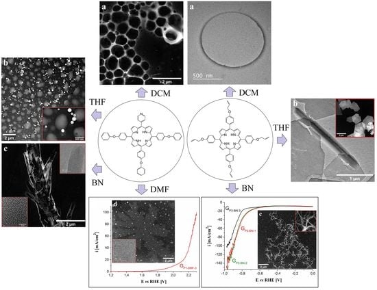
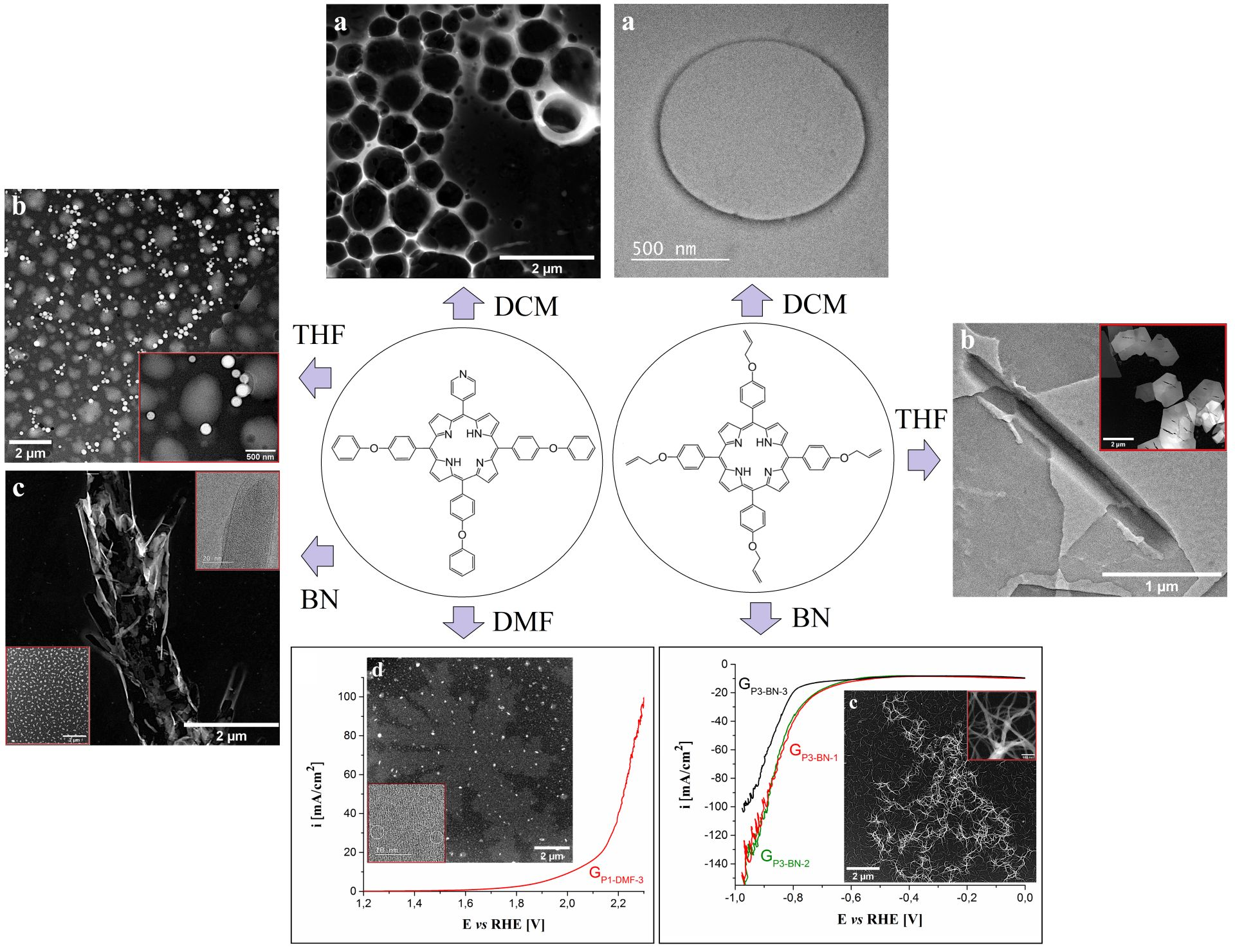
3.1. TEM/STEM Analysis of Porphyrin Specimens

The TEM and STEM images recorded for the four free-base porphyrins are presented in Figure 1 and Figure 2. By applying the porphyrins on nonpolar carbon films from solutions obtained with organic solvents having different polarities, various structures were formed via the self-assembly property of the macrocycles. In the case of asymmetrical P1, when using DCM as a solvent, a fishing net-like structure comprised of eyelets with various micrometric and submicrometric dimensions was observed (Figure 1a). When employing THF to obtain the P1 solution, the TEM specimen analysis evidenced island-like aggregates with sizes ranging from several tens of nanometers to the micrometer domain, as well as spherical formations with submicrometric diameters (Figure 1b). These observations are in agreement with previously published data [44,45]. The organizing of the P1 molecules in more than one type of structure indicates that the balance between weak intermolecular hydrogen bonding/hydrophobic interactions might be the governing factor in the self-assembly process [28]. Figure 1c shows the formations identified after the drop-casting of P1 from BN. The macrocycles are arranged as structures that resembled a tree trunk with branches extending for several micrometers in length. The inset in the lower part of the image outlines the surface area surrounding them, covered with smaller (submicrometric), uniformly distributed and irregular aggregates. The inset in the upper corner is an HR-TEM image of the tip of one of the branch-shaped assemblages and evidences a couple of partially overlapping amorphous layers, which is indicative of a self-aggregation process involving H-aggregates. Lastly, the specimen obtained by applying P1 from DMF on the TEM grid also showed more types of porphyrin architecture (Figure 1d). The largest formations bore striking resemblance to ferns that extended for more than 10 µm in length and were dotted with irregularly shaped submicrometric aggregates. The inset presents an HR-TEM image recorded on the fern-like structure from Figure 1d and outlines the presence of crystallites with diameters as small as 3 nm. Measurements performed on such crystallites reveal an interplanar spacing of 2.75 Å and their presence indicates that the porphyrin molecules are able to organize well enough to form a stable crystalline lattice.
The specimens resulted by applying P2 on TEM grids from solutions in which DCM, THF and BN were employed as solvents, presented in Figure 1e–g, respectively. In the first case, the porphyrin molecules formed similar aggregates to the ones observed for the P1 porphyrin, obtained using the same solvent. In the second case, molecular self-assembly led to a variety of structures, some of which displayed a tendency to organize as circles. Figure 1g shows the co-existence of different types of structures—bundles and fibers that interact with a discontinuous layer covering a large part of the carbon film surface.
The P3 specimens drop-casted from DCM, THF and BN are presented in Figure 2a–c. The structure shown in Figure 2a is an example of the type of aggregate that the porphyrin molecules constitute when applied from DCM, and it is in agreement with other studies [60]. The tendency of P3 molecules applied from THF (Figure 2b) to self-assemble as elongated structures with micrometric length and submicrometric breadth, as well as polygonal plates (shown in the inset) with micrometric dimensions and crevices across the surface, has also been previously observed [45]. Very different reticulated arrangements were evidenced for the specimen obtained using BN. The surface of the carbon film was covered with uniformly distributed fiber-like aggregates, and there were areas where many such structures further assembled to give rise to large disordered flocculated formations. The inset in Figure 2c displays a TEM photograph recorded at high magnification on fiber-like structures belonging to such a formation. Measurements of individual fibers outlined their nanometric thickness, varying between 10 and 25 nm.
The remaining images from Figure 2d–f, present the results for the specimens obtained by applying P4 on TEM grids from DCM, THF and BN, respectively. In the first case, a fishing net-like structure was once again evidenced, as when P1 and P2 were deposited from the same solvent. The porphyrin molecules were concentrated so as to form the contours of geometrical figures. Furthermore, this behavior was observed for the P3 specimen as well (Figure 2a), even if, in this case, the net-like arrangement was absent. The shared feature of the self-assembly process does not depend significantly on the porphyrin substituents, but on the properties of the solvent and of the support, both of which were hydrophobic. DCM wets the carbon film substrate to a high degree, forming a pellicle on its surface. This means that when the porphyrin solution is drop-casted on the support and gives rise to ring-like aggregates, the likely surface-drying mechanism is the pinhole mechanism [61,62]. As for the difference between the structure evidenced on the P3 specimen and the ones from the other specimens, obtained using DCM, it can be attributed to the influence of the allyloxy substituents. Figure 1e shows micrometric and submicrometric water lily-shaped arrangements that are either complete or at different stages of development. A more detailed description of these formations can be found in [60]. The last image from Figure 2 displays highly ramified fractal structures resembling fern leaves that extend for several micrometers and develop from the aggregation of P4 molecules applied from BN on the TEM grid.
As a general observation, besides some similarities among the structures presented in Figure 2 and Figure 3, there are clearly many differences, especially in terms of complexity. These are probably due to the interplay between the differently substituted porphyrins (that might cause the distortion of the molecules), their hydrophilic/hydrophobic balance, the different properties of the solvents used to obtain the porphyrin solutions and the carbon film surface.

3.2. OER and HER Electrocatalytic Properties of the Porphyrin Modified Electrodes

3.2.1. Studies in 0.1 M KOH Electrolyte Solution

LSVs traced on the porphyrin modified electrodes in 0.1 M KOH solution are presented in Figure S1 from the SDF. Figure S1a–c show the polarization curves obtained using the P1 modified electrodes, manufactured by applying one (Figure S1a), two (Figure S1b) and three porphyrin layers (Figure S1c) on the graphite substrate. The O2 evolution overpotential (ηO2) was determined at i = 10 mA/cm2, in agreement with reported studies [54,63,64]. Besides the ηO2 value, the maximum i value was also considered, as it is indicative of an electrocatalyst’s efficiency [65,66]. All electrodes modified with P1 applied from DMF displayed a ηO2 of ~1 V, but the highest i value (i = 19.1 mA/cm2) was evidenced for the electrode having three porphyrin layers (Figure S1c). Consequently, this electrode was selected for further investigation in terms of its OER electrocatalytic properties in a strong alkaline medium. In the case of the electrodes modified with P2 (Figure S1d–f), the use of BN to cast the porphyrin on the graphite surface led to better results overall (ηO2 = ~0.99 V and maximum i values between 15.1 and 17.9 mA/cm2) and, because of this, GP2-BN-1, GP2-BN-2 and GP2-BN-3 were chosen for further study. Regarding P3 (Figure S1g–i), the maximum i values were observed for GP3-DCM-1, GP3-DCM-2 and GP3-DCM-3. Since GP3-DCM-1O2 = 0.99 V) is the easiest to manufacture and requires the least amount of porphyrin out of the three specified electrodes, it was selected for further investigation. Lastly, the LSVs recorded for the P4-based electrodes (Figure S1j–l) showed the smallest of the maximum i values (<15 mA/cm2), while the determined ηO2 values were between 0.99 and 1.03 V. Because of the low i values, the electrodes modified with this porphyrin species were not subjected to further experiments.
The cathodic polarization curves recorded in the 0.1 M KOH solution, using the porphyrin-based electrodes, are shown in Figure S2 from the SDF. In the case of the P1-modified electrodes (Figure S2a–c), GP1-DCM-1 displayed the lowest ηH2 value at i = −10 mA/cm2 (0.71 V), as well as the lowest i value (−66 mA/cm2). Because of this, it was selected for further investigation in a 1 M KOH solution. For all the remaining electrodes, the best results were obtained when P2, P3 and P4 were drop-casted from BN (Figure S2d–l). The ηH2 values calculated for these electrodes at i = −10 mA/cm2 were either higher or very similar to the ones determined for the electrodes modified using the same porphyrins but applied from different solvents. Most importantly, these cathodes achieved the lowest i values in all cases and, therefore, were chosen for further study in terms of their HER catalytic properties.
As a general conclusion, the HER and OER electrocatalytic behavior in the 0.1 M KOH electrolyte solution of the porphyrin-based electrodes is influenced by the polarity of the solvent used in the manufacturing process, and, in most cases, the number of casted layers has no significant impact on the observed catalytic performance. The experimental results allowed for the identification of the most electrocatalytically active electrodes that were subsequently evaluated in the strong alkaline medium.

3.2.2. OER Electrocatalytic Properties of the Porphyrin Modified Electrodes in 1 M KOH Solution

The anodic LSV recorded for the GP1-DMF-3 electrode in 1 M KOH electrolyte solution is presented in Figure 3a. The strong alkaline medium led to a decrease in the OER overpotential and an increase in the maximum current density, compared to the weaker alkaline medium (0.1 M KOH solution)—a behavior that has previously been reported for other catalysts [67]. Thus, ηO2 = 0.78 V at i = 10 mA/cm2, while the maximum i value observed in the scanned potential range is 99.68 mA/cm2. The inset from Figure 3a highlights the polarization curves traced in 0.1 M KOH solution on the electrodes modified with P1 applied from DMF on the graphite support. The electrode manufactured by drop-casting three layers of P1 on the graphite surface displays the best OER catalytic activity. The EASA value for the GP1-DMF-3 electrode was estimated using the Randles–Sevcik equation and data from cyclic voltammograms recorded in 1 M KNO3 solution, in the presence and absence of 4 mM K3[Fe(CN)6], and at different scan rates (v = 50, 100, 150, 200, 250, 300 and 350 mV/s). The calculated value for two sets of experiments is 0.513 ± 0.02 cm2 and the diffusion coefficient of ferricyanide ions is 2.26 × 10⁻⁵ ± 0.18 × 10⁻⁵ cm2/s. The plot presented in Figure 3b shows the dependence between the peak current densities of the anodic and cathodic peaks corresponding to the ferri-/ferrocyanide redox couple and the square root of the scan rate. As the scan rate increases, so do the absolute values of the peak current densities, indicating a behavior characteristic of a diffusion-controlled electron transfer process [68]. The OER kinetics at the GP1-DMF-3 electrode/1 M KOH solution interface were investigated as well, and the Tafel slope value was calculated using the Tafel equation and the Tafel plot from Figure 3c is 0.343 V/dec. The stability of the modified electrode was evaluated chronoamperometrically, and Figure 3d presents the i-time curve recorded for 6 h on the porphyrin-based electrode while maintaining constant the E value corresponding to i = 10 mA/cm2. In the first 15 min, the current density value decreased until it reached 7.9 mA/cm2. After this time, it gradually increased to 17.4 mA/cm2 (at the 320th minute) and remained constant until the end of the experiment. Even though the i value changed significantly during the stability test, when the LSVs recorded before and after it were overlapped (inset in Figure 3d), a decrease from 0.78 V to 0.74 V in the OER overpotential (at i = 10 mA/cm2) was observed. However, the ηO2 values became higher at current density values above 15.5 mA/cm2, and the maximum recorded i value became smaller than before the experiment.
The OER catalytic activity of the GP2-BN-1, GP2-BN-2 and GP2-BN-3 electrodes was also investigated and the traced anodic polarization curves are presented in Figure 4a. There are no significant differences between the LSVs, which means that the increase in the number of applied P2 layers on the graphite support had no remarkable effect on the OER catalytic performance of the electrodes. The smallest ηO2 value (of 0.78 V) was observed for the GP2-BN-1 electrode, which is also the easiest to manufacture, and was further investigated. The inset from Figure 4a allows for a comparison between the voltammograms recorded on the three electrodes in 0.1 M and 1 M KOH solutions. The KOH concentration increase has led to smaller overpotential values and a higher maximum of current density values. The EASA and the diffusion coefficient of ferricyanide ions values were estimated using the same procedure employed for the GP1-DMF-3 electrode, and they are 1.174 ± 0.09 cm2 and 1.18 × 10⁻⁴ ± 0.18 × 10⁻⁴ cm2/s, respectively. As in the case of the previously studied electrode, the linear dependence between the absolute values of the peak current densities with the scan rate indicated a diffusion-controlled electron transfer process (Figure 4b). The Tafel slope, calculated based on the Tafel plot shown in Figure 4c, was found to be 0.35 V/dec. The i-time curve recorded on the GP2-BN-1 electrode, at the constant E value corresponding to i = 10 mA/cm2, is presented in Figure 4d and shows that the i value gradually increased from 10.6 mA/cm2 (the 5th minute) to 27 mA/cm2 (the 250th minute), where it remained constant until the end of the experiment. This change is significant and the inset from Figure 4d suggests that the stability test led to a decrease in the OER electrocatalytic performance of the modified electrode.
Figure 5 presents the results obtained from the evaluation of the GP3-DCM-1 electrode’s OER catalytic properties. As with the previously studied electrodes, the strong alkaline medium (1 M KOH solution) had a positive effect on the OER catalytic activity of this electrode. Thus, based on the anodic polarization curve in Figure 5a, the ηO2 value (at i = 10 mA/cm2) is 0.85 V and the maximum i value is 74 mA/cm2. The OER catalytic activity of the GP3-DCM-1, GP3-DCM-2 and GP3-DCM-3 modified electrodes was not as good in the 0.1 M KOH solution (inset from Figure 5a). The EASA and diffusion coefficient values calculated for the GP3-DCM-1 electrode are 0.424 ± 0.019 cm2 and 1.545 × 10⁻⁵ ± 0.14 × 10⁻⁵ cm2/s. Figure 5b outlines the fact that the electron transfer process is diffusion-controlled, as was the case with the GP1-DMF-3 and GP2-BN-1 electrodes. The Tafel plot (Figure 5c) for the GP2-BN-1 electrode, in 1 M KOH solution, was used to determine the Tafel slope value of 0.34 V/dec. The i-time curve obtained during the chronoamperometric stability test shows a gradual increase in current density from the 10.7 mA/cm2 value (observed at the 4th minute) to the 22 mA/cm2 value (seen at the end of the test). The inset from Figure 5d presents the LSVs traced in 1 M KOH electrolyte solution before and after the test. The curves do not overlap entirely and an increase in overpotential can be noticed for the voltammogram recorded after the stability test—more prominently in the current density interval between 4 and 20 mA/cm2 (at i = 10 mA/cm2, ηO2 = 0.9 V).
Out of the three porphyrin modified graphite electrodes (GP1-DMF-3, GP2-BN-1 and GP3-DCM-1) studied in 1 M KOH electrolyte solution in terms of their OER electrocatalytic properties overpotential, maximum current density and Tafel plot values and electrochemical stability, the one manufactured using P1 is, overall, more performant than the others. This might be due to the higher polarizability of this A3B porphyrin and to its capacity to distort from the planar structure into saddle-like conformation. To elucidate these hypotheses, the electrodes were characterized, before and after the stability test, using non-electrochemical methods, such as SEM microscopy and Raman spectra (further discussed in Section 3.3 of this paper). Raman spectra presented in Figure S3a from the SDF, clearly show that no significant structural changes occur during the investigations using these two electrodes.

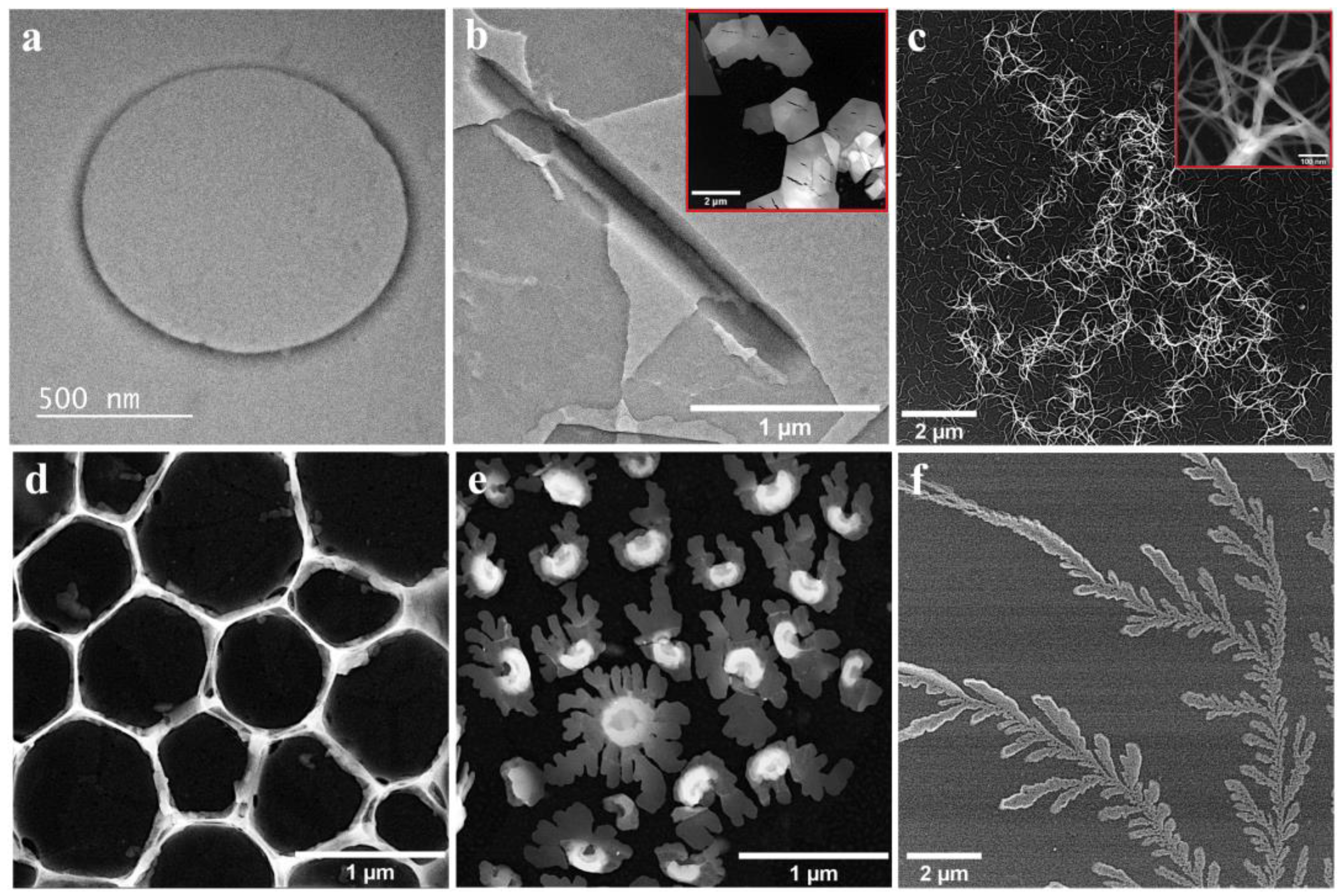
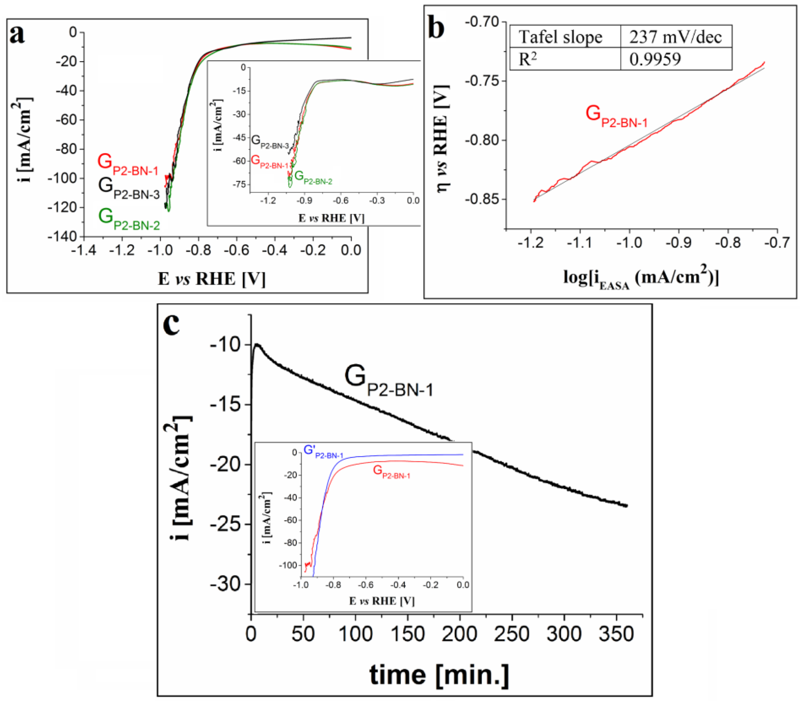
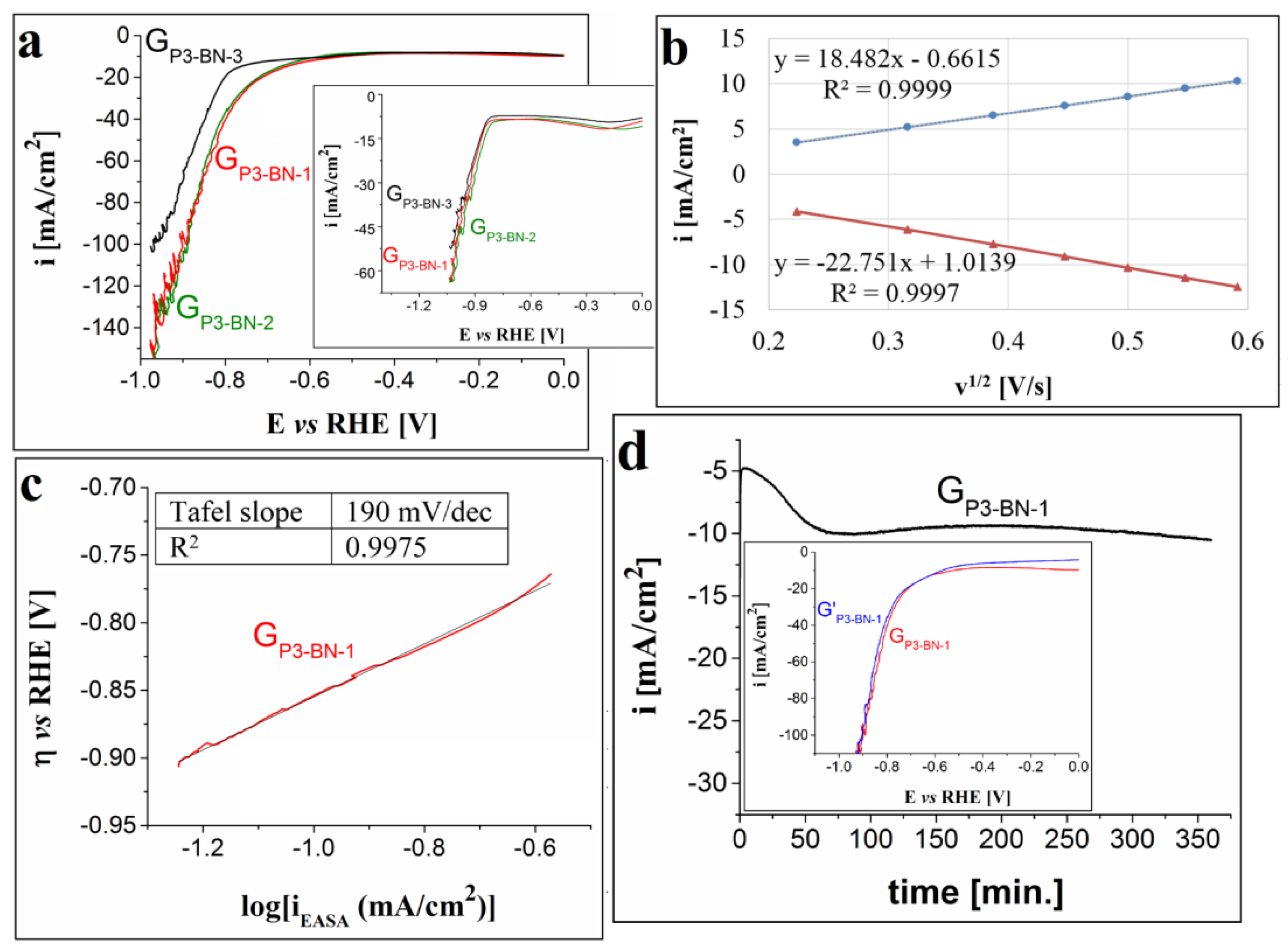
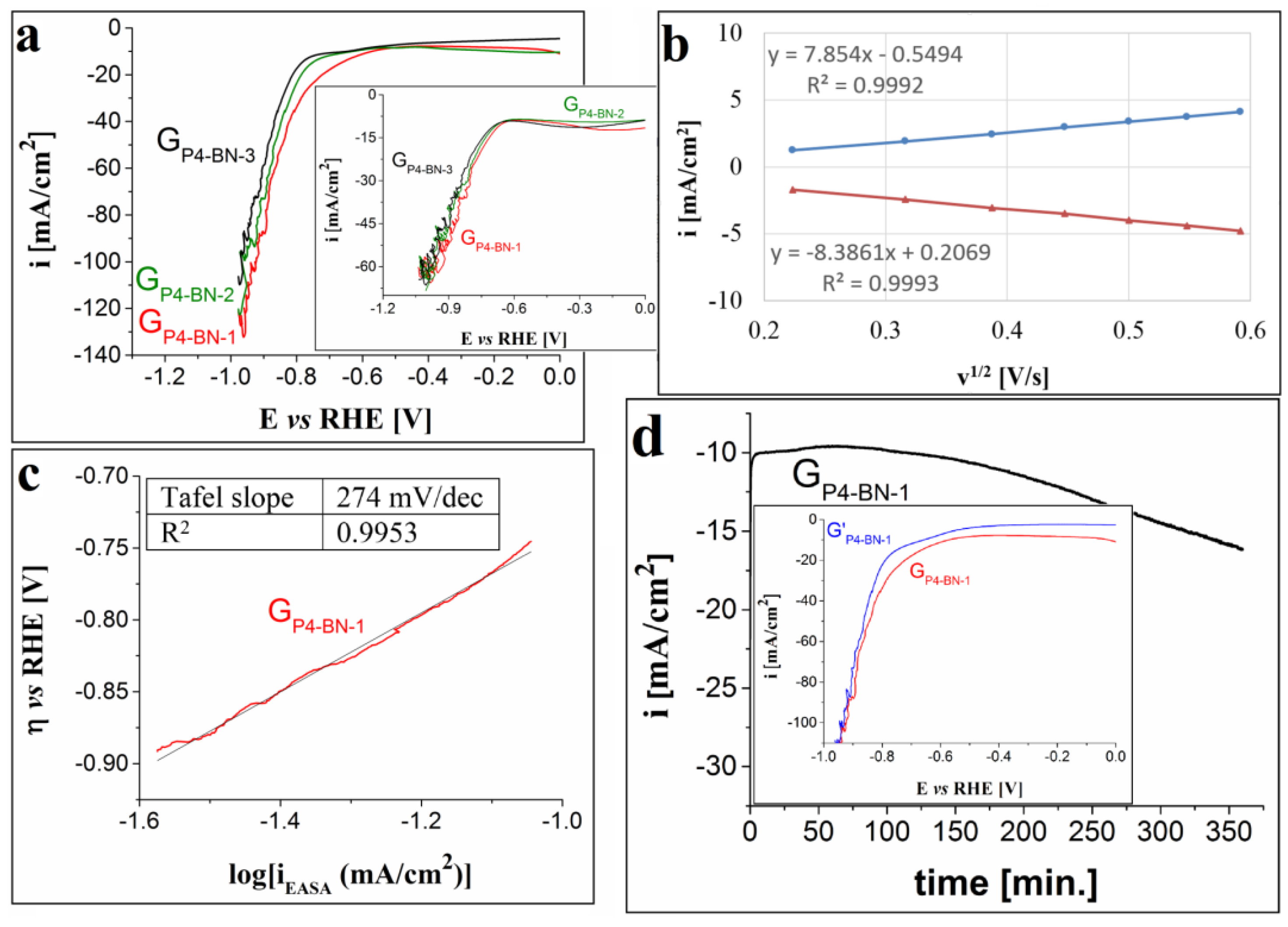
3.2.3. HER Electrocatalytic Properties of the Porphyrin Modified Electrodes in 1 M KOH Solution

The cathodic polarization voltammogram traced in the strong alkaline medium on the GP1-DCM-1 electrode is presented in Figure 6a. The obtained ηH2 value at i = −10 mA/cm2 is 0.6 V, which is smaller than in 0.1 M KOH solution (Figure 6a inset), and the minimum i value (−100 mA/cm2) is lower than the one observed in the weaker alkaline medium. The EASA and diffusion coefficient values for this electrode were found to be 1.27 ± 0.11 cm2 and 1.4 × 10⁻⁴ ± 0.2 × 10⁻⁴ cm2/s, respectively. The plot showing the relationship between the peak current densities of the anodic and cathodic peaks corresponding to the ferri-/ferrocyanide redox couple and v1/2 (Figure 6b) indicates that the electron transfer process was controlled by diffusion. The Tafel slope determined using the Tafel equation and the Tafel plot (Figure 6c) is 239 mV/dec. This value is smaller than the ones calculated for the electrodes investigated in terms of their OER properties and it suggests faster electrode kinetics [69]. The electrochemical stability of the GP1-DCM-1 electrode was also studied by applying a constant E value corresponding to i = −10 mA/cm2. The recorded chronoamperogram is presented in Figure 6d together with an inset showing the cathodic curves obtained before and after the test. The electrode’s stability is rather poor since the −10 mA/cm2 current density value is reached after 20 min and decreases to −23 mA/cm2 by the end of the experiment. The LSV traced after the test evidences an increase in the HER overpotential (from 0.6 V to 0.74 V, at i = −10 mA/cm2).
In the case of the electrodes modified using P2, P3 and P4 drop-casted from BN, the cathodic polarization curves traced in 1 M KOH solution are presented in Figure 7a, Figure 8a and Figure 9a. The results show the following: the voltammogram obtained using electrodes modified with one layer of P2 overlaps to a large extent with the ones traced on the electrodes manufactured with two and three layers; the LSVs recorded on the electrodes with one and two layers of P3 are very similar and outline smaller HER overpotential values than the ones determined for the curve obtained on the electrode with three layers of the same porphyrin; and the polarization curve obtained on the GP4-BN-1 electrode evidences the smallest overpotential values among the P4-based modified electrodes. Taking these observations into account, together with the fact that it is easier and cheaper to manufacture electrodes with one porphyrin layer, subsequent studies regarding the HER electrocatalytic properties of the porphyrin-modified electrodes were performed only on GP2-BN-1, GP3-BN-1 and GP4-BN-1. Compared with the LSVs recorded in 0.1 M KOH solution (insets from Figure 7a, Figure 8a and Figure 9a), the ones traced in the stronger alkaline medium display smaller ηH2 values (at i = −10 mA/cm2) and lower minimum current densities. For GP2-BN-1 ηH2 = 0.64 V and the minimum i value (imin) is −105 mA/cm2, for GP3-BN-1 ηH2 = 0.5 V and imin = −154 mA/cm2 and for GP4-BN-1 ηH2 = 0.57 V and imin = −131 mA/cm2. The estimated EASA and diffusion coefficient values were already presented for the GP2-BN-1 electrode (see Section 3.2.2), whereas, for the other electrodes, they are as follows: 1.205 ± 0.07 cm2 and 1.245 × 10⁻⁴ ± 0.16 × 10⁻⁴ cm2/s in the case of the GP3-BN-1 electrode, and 0.58 ± 0.03 cm2 and 2.865 × 10⁻⁵ ± 0.38 × 10⁻⁵ cm2/s for GP4-BN-1. Based on the plots depicted for the GP3-BN-1 and GP4-BN-1 electrodes, outlining the relationship between the peak current densities of the anodic and cathodic peaks corresponding to the ferri-/ferrocyanide redox couple and v1/2 (Figure 8b and Figure 9b), it can be said that, in both cases, the electron transfer process was diffusion-controlled. As was explained in Section 3.2.2, this is also the case with the GP2-BN-1 electrode. The linear regions of the Tafel plots obtained for the three electrodes (Figure 7b, Figure 8c and Figure 9c) were fitted using the Tafel equation and the values of the Tafel slopes were 237 mV/dec for GP2-BN-1, 190 mV/dec for GP3-BN-1 and 274 mV for GP4-BN-1. These values evidence faster electrode kinetics than observed in the OER studies.
In terms of stability, the GP2-BN-1, GP3-BN-1 and GP4-BN-1 electrodes were tested under the same experimental conditions as GP1-DCM-1. The obtained i vs. time curves are shown in Figure 9c and Figure 10d, respectively. By comparing these results, it can be seen that GP3-BN-1 was the most stable electrode. The current density decreased from −5 mA/cm2 to −10 mA/cm2 in the first 70 min, and this value remained relatively constant until the end of the study, when i = −10.5 mA/cm2. Based on the inset added to each figure, the smallest deviations in the LSVs obtained before and after the test were observed for the electrode manufactured using P3.
As a conclusion to the study concerning the HER electrocatalytic properties of the GP1-DCM-1, GP2-BN-1, GP3-BN-1 and GP4-BN-1 electrodes in 1 M KOH electrolyte solution, the cathode manufactured by applying one layer of P3 porphyrin, grafted with the allyloxy functional group on the graphite substrate using BN as a solvent is the most performant. GP3-BN-1 was further analyzed with physical–chemical characterization methods, and the SEM images and Raman spectra obtained on the electrode before and after the chronoamperometric stability test are presented in Figure 10e–g and Figure S3b from the SDF.

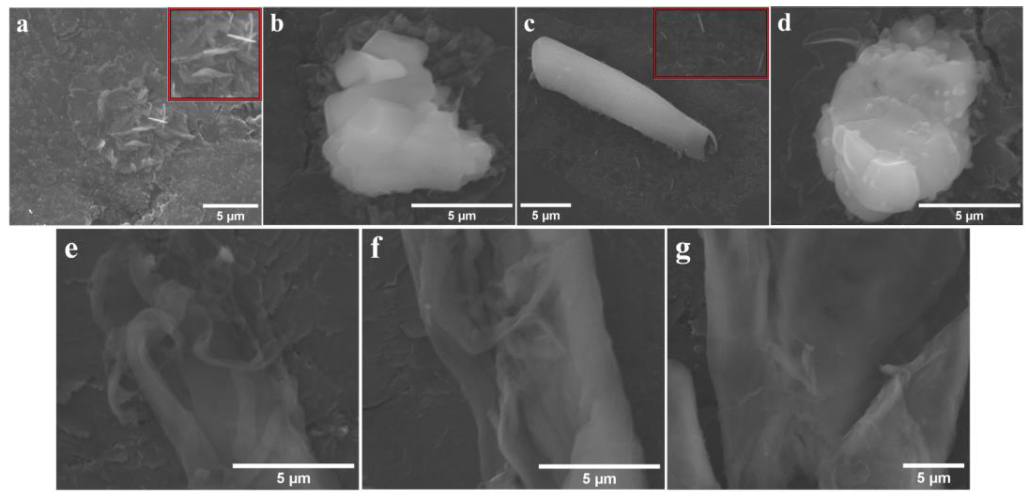
3.3. SEM and Raman Characterizations

SEM analysis was employed to study the surface of the GP1-DMF-3 and GP3-BN-1 modified electrodes, before and after the electrochemical stability test (Figure 10).
Figure 10a, recorded on the GP1-DMF-3 electrode before the chronoamperometric test, shows an inhomogeneous layer covering the surface of the graphite support, as well as a few needle-like aggregates with micrometric and submicrometric length. The inset presents an enlarged area from the SEM image containing the specified assemblies. Figure 10b, also traced before the test, evidences an irregularly shaped structure. Needle-like formations (inset) are outlined in Figure 10c (obtained after the chronoamperometric test) and are situated near an elongated roll-like aggregate that might have the advantage of double faces active surface. An inhomogeneous fibrous layer covering the substrate surface can be observed as well and increases the specific surface area. Lastly, Figure 10d, recorded after the test, shows an irregular structure. The similarities between the two pairs of images (Figure 10a,b vs. Figure 10c,d) indicate that the GP1-DMF-3 electrode did not undergo any significant changes during the electrochemical stability investigation. The same can be concluded about the GP3-BN-1 electrode, where fiber-like formations were present both before (Figure 10e) and after (Figure 10f,g) the test. It should also be reiterated that the same types of aggregates were evidenced during the TEM/STEM analysis.
Raman spectroscopy is another characterization technique that was employed to analyze the two electrodes before and after the stability experiment, with the traced spectra being presented in Figure S3 from the SDF. In the case of the GP1-DMF-3 electrode, the signals observed on the spectra recorded for the unmodified graphite electrode (G0) and for P1 are also present on those obtained for the modified electrode before and after the chronoamperometric test, except where the peak that appears at 1355 cm−1 on the graphite electrode spectrum covers the signals evidenced for the porphyrin spectrum. The same situation is outlined for the spectra traced on G0, P3 and the GP3-BN-1 electrode (before and after the test). These results further support the conclusion of the SEM analysis, namely, that the two electrodes did not suffer any significant structural changes during the investigation.

3.4. Further Considerations Regarding the GP3-BN-1 Electrode

Out of the electrodes modified with free-base porphyrins drop-casted on the surface of graphite supports from solutions prepared using solvents with different polarities in one, two or three layers, the most electrocatalytically active electrode for water-splitting in the strong alkaline medium is GP3-BN-1. Its superior catalytic properties are probably due to extended π-resonance, structural and transport effects. There are some aspects that should be emphasized: (a) the TEM analysis (Figure 2c) revealed that the P3 fiber-like aggregates are distributed uniformly on the carbon substrate, but the more complex structures are disordered. Thus, they provide a degree of inhomogeneity that constitutes an advantage in terms of catalytic performance, since surface inhomogeneities act as a generator of more catalytically active sites [70,71]. Furthermore, the EASA value estimated for the GP3-BN-1 electrode is relatively high, which is also indicative of the presence of inhomogeneities [17]. (b) One of the problems facing electrodes modified with heterogeneous catalysts for water splitting is that the deposited catalytic materials can organize in ways that prevent the electrolyte solution from reaching the deep pores of the applied layer [72,73]. This phenomenon negatively impacts the electrode’s EASA and, consequently, its catalytic performance. Since the estimated EASA value for GP3-BN-1 is more than four times higher than its geometrical surface, it is unlikely that the specified issue affects the electrode in a very significant way. (c) Charge transfer between porphyrin macromolecules occurs through non-covalent π–π interactions, and when the electrode is immersed into the electrolyte solution, there is the possibility for another such type of interaction occurring: intermolecular hydrogen bonding between the substituents of neighboring porphyrin macromolecules via water molecules [33]. In the case of P3, the ether oxygen atom from the 4-allyloxyphenyl substituents could form such bonds that would also induce negative charge transfer from the graphite support to the P3 layer. (d) Another way transfer effects between the drop-casted porphyrin molecules and the substrate occur is through differences in atomic electronegativity. The atoms in question are the N atoms of the porphyrin macrocycle that are more electronegative than the C atoms of the graphite and induce positive charges on its surface [33].
A literature survey was performed in order to compare the HER electrochemical activity of the GP3-BN-1 electrode with that of other metal-free electrodes evaluated in 1 M KOH electrolyte solution and reported in the past 10 years. The findings indicate that while HER studies in a 0.1 M KOH solution are relatively easy to find, investigations performed in a strong alkaline medium are quite scarce. Still, a few relevant articles have been identified and the electrodes used, together with the ηH2 and Tafel slope values, are presented in Table 2.
The ηH2 value for the GP3-BN-1 electrode is comparable to the ηH2 values for the electrodes specified in Table 2, but its Tafel slope value is smaller, indicating faster electrode kinetics. The explanation for faster electrode kinetics relies on the capacity of these larger specific surface areas—double faces roll-like aggregates or inhomogeneous fibrous formations (Figure 10)—to promote both easily accessible and more actively catalytic sites at the thin films interface, thus providing high interaction with water in an alkaline medium. Excepting the scan rate, the concentration of the catalyst was controlled, and due to using an alkaline medium, we could also control the type of the electroactive species [81]. The control is more difficult if there are more than one electroactive species in the system. However, the HER electrocatlytic properties of the GP3-BN-1 electrode are not as good as those of the commercial 20% Pt/C catalyst on a glassy carbon substrate, which displays an HER overpotential value of 51 mV at i = −10 mA/cm2 and a Tafel slope value of 24 mV/dec, in 1 M KOH electrolyte solution [82]. The same is true for the OER properties of the GP1-DMF-3 electrode when compared with the IrO2 and RuO2 commercial catalysts. Thus, for GP1-DMF-3, ηO2 = 670 mV at i = 5 mA/cm2 and 780 mV at i = 10 mA/cm2, and its Tafel slope value is 343 mV/dec, in 1 M KOH solution. In the same medium, IrO2 on glassy carbon support displays an OER overpotential value of ~530 mV at i = 5 mA/cm2 and a Tafel slope of 189 mV/dec [83], while RuO2 shows a ηO2 value of 301 mV at i = 10 mA/cm2 and a Tafel slope value of 100 mV/dec [84].

4. Conclusions

Four free-base porphyrins were studied as heterogeneous catalysts for the OER and HER in an alkaline medium. The macromolecules were drop-casted from different organic solvents on TEM grids (in one layer) and graphite substrates (in one, two and three layers). TEM/STEM analysis evidenced a rich variety of aggregates resulting from the self-assembling of the porphyrin molecules. The observed diversity is due to the distorted conformation of differently substituted porphyrins, the polarity of the solvents and the carbon film surface. The acquired data complement the existent literature regarding the self-assembly of free-base porphyrins.
The OER and HER electrocatalytic activities of the electrodes modified with porphyrins were initially investigated in 0.1 M KOH electrolyte solution. The experiments conclude that the water-splitting behavior of the modified electrodes is influenced by the polarity of the used solvent, but the number of casted layers has no significant impact on the catalytic performance. The best electrocatalytically active electrodes were further evaluated in a strong alkaline medium.
In terms of their OER electrochemical behavior, the electrode modified by applying three layers of 5-(4-pyridyl)-10,15,20-tris(4-phenoxyphenyl)-porphyrin from the DMF solution on the graphite was identified as being overall catalytically superior, probably due to the higher polarizability of this A3B porphyrin. In the case of the HER experiments conducted using the same electrolyte solution, the electrode obtained by applying one layer of 5,10,15,20-tetrakis(4-allyloxyphenyl)-porphyrin from the BN solution on the conductive support was found to be the most electrochemically performant. It displayed an overpotential value of 500 mV at i = −10 mA/cm2 and a Tafel slope value of 190 mV/dec, so that faster electrode kinetics were achieved.
The stability of the electrodes was evidenced and proved via SEM and Raman analyses, before and after chronoamperometric tests.
More investigations relevant to the water splitting domain that involve the four free-base porphyrins studied in the present work—but in combination with inorganic compounds—are underway.

Supplementary Materials

The following supporting information can be downloaded at: https://www.mdpi.com/article/10.3390/pr10030611/s1, Scheme S1: The chemical structures of: (a) 5-(4-pyridyl)-10,15,20-tris(4-phenoxyphenyl)-porphyrin; (b) 5,10,15,20-tetrakis(4-methoxyphenyl)-porphyrin; (c) 5,10,15,20-tetrakis(4-allyloxyphenyl)-porphyrin and (d) 5,10,15,20-tetrakis(p-tolyl)-porphyrin; the equations used to express the E values vs. RHE, to calculate the O2 and H2 evolution overpotential values, to determine the Tafel slope values and the Randles–Sevcik equation; Figure S1: Anodic polarization curves recorded on the porphyrin modified graphite electrodes in 0.1 M KOH solution, at v = 1 mV/s. The electrode codes are the ones specified in Table 1, and G0 (from Figure S1a) is the unmodified graphite electrode; Figure S2: Cathodic polarization curves traced on the porphyrin modified graphite electrodes in 0.1 M KOH solution, at v = 5 mV/s. The electrode codes are the ones specified in Table 1, and G0 (from Figure S2a) is the unmodified graphite electrode; Figure S3: Raman spectra recorded on: (a) G0, P1 and the GP1-DMF-3 electrode before and after the chronoamperometric test (GP1-DMF-3 and G’P1-DMF-3, respectively); (b) G0, P3 and the GP3-BN-1 electrode before and after the chronoamperometric test (GP3-BN-1 and G’P3-BN-1, respectively).

Author Contributions

Conceptualization, E.F.-C. and B.-O.T.; methodology, E.F.-C. and B.-O.T.; software, E.F.-C. and B.-O.T.; validation, E.F.-C. and B.-O.T.; formal analysis, E.F.-C. and B.-O.T.; investigation, E.F.-C. and B.-O.T.; resources, E.F.-C. and B.-O.T.; data curation, E.F.-C. and B.-O.T.; writing—original draft preparation, E.F.-C. and B.-O.T.; writing—review and editing, E.F.-C. and B.-O.T.; supervision, E.F.-C.; project administration, E.F.-C.; funding acquisition, E.F.-C. All authors have read and agreed to the published version of the manuscript.

Funding

This research was funded by UEFISCDI, project number PN-III-P2-2.1-PED-2019-0487, 528PED/2020, CeraPor-Corr, “Hybrid ceramics/porphyrins, deposited by pulsed laser deposition as single and sandwich layers for corrosion inhibition of steels in acid environment”, and partially by the Romanian Academy through Programme 3/2022 from the Institute of Chemistry, “Coriolan Dragulescu”.

Institutional Review Board Statement

Not applicable.

Informed Consent Statement

Not applicable.

Data Availability Statement

Not applicable.

Acknowledgments

The authors gratefully acknowledge and would like to thank Paula Sfirloaga and Stefania Florina Rus, from the National Institute for Research and Development in Electrochemistry and Condensed Matter (Timisoara, Romania), for recording the SEM images and the Raman spectra.

Conflicts of Interest

The authors declare no conflict of interest.

References

  1. Sharma, S.; Agarwal, S.; Jain, A. Significance of Hydrogen as Economic and Environmentally Friendly Fuel. Energies 2021, 14, 7389. [Google Scholar] [CrossRef]
  2. Gao, Z.; Qi, J.; Chen, M.; Zhang, W.; Cao, R. An Electrodeposited NiSe for Electrocatalytic Hydrogen and Oxygen Evolution Reactions in Alkaline Solution. Electrochim. Acta 2017, 224, 412–418. [Google Scholar] [CrossRef]
  3. Li, Q.; Bao, Y.; Bai, F. Porphyrin and Macrocycle Derivatives for Electrochemical Water Splitting. MRS Bull. 2020, 45, 569–573. [Google Scholar] [CrossRef]
  4. Fellet, M.; Tiede, D.M. Search for Water-Splitting Catalysts for Global Usage. Mater. Res. Bull. 2017, 42, 190–191. [Google Scholar] [CrossRef] [Green Version]
  5. Li, Q.; Mahmood, N.; Zhu, J.; Hou, Y.; Sun, S. Graphene and Its Composites with Nanoparticles for Electrochemical Energy Applications. Nano Today 2014, 9, 668–683. [Google Scholar] [CrossRef] [Green Version]
  6. Marwat, M.A.; Humayun, M.; Afridi, M.W.; Zhang, H.; Abdul Karim, M.R.; Ashtar, M.; Usman, M.; Waqar, S.; Ullah, H.; Wang, C.; et al. Advanced Catalysts for Photoelectrochemical Water Splitting. ACS Appl. Energy Mater. 2021, 4, 12007–12031. [Google Scholar] [CrossRef]
  7. Mallouk, T.E. Divide and Conquer. Nat. Chem. 2013, 5, 362–363. [Google Scholar] [CrossRef]
  8. Kuang, Y.; Kenney, M.J.; Meng, Y.; Hung, W.H.; Liu, Y.; Huang, J.E.; Prasanna, R.; Li, P.; Li, Y.; Wang, L.; et al. Solar-Driven, Highly Sustained Splitting of Seawater into Hydrogen and Oxygen Fuels. Proc. Natl. Acad. Sci. USA 2019, 116, 6624–6629. [Google Scholar] [CrossRef] [Green Version]
  9. Peng, J.; Dong, W.; Wang, Z.; Meng, Y.; Liu, W.; Song, P.; Liu, Z. Recent Advances in 2D Transition Metal Compounds for Electrocatalytic Full Water Splitting in Neutral Media. Mater. Today Adv. 2020, 8, 100081. [Google Scholar] [CrossRef]
  10. Zhang, M.; Wang, T.; Cao, H.; Cui, S.; Du, P. Self-Supported Ni2P Nanosheets on Low-Cost Three-Dimensional Fe Foam as a Novel Electrocatalyst for Efficient Water Oxidation. J. Energy Chem. 2020, 42, 71–76. [Google Scholar] [CrossRef] [Green Version]
  11. Liang, Y.; Li, Y.; Wang, H.; Dai, H. Strongly Coupled Inorganic/Nanocarbon Hybrid Materials for Advanced Electrocatalysis. J. Am. Chem. Soc. 2013, 135, 2013–2036. [Google Scholar] [CrossRef]
  12. Lee, Y.; Suntivich, J.; May, K.J.; Perry, E.E.; Shao-Horn, Y. Synthesis and Activities of Rutile IrO2 and RuO2 Nanoparticles for Oxygen Evolution in Acid and Alkaline Solutions. J. Phys. Chem. Lett. 2012, 3, 399–404. [Google Scholar] [CrossRef] [PubMed]
  13. Reier, T.; Oezaslan, M.; Strasser, P. Electrocatalytic Oxygen Evolution Reaction (OER) on Ru, Ir, and Pt Catalysts: A Comparative Study of Nanoparticles and Bulk Materials. ACS Catal. 2012, 2, 1765–1772. [Google Scholar] [CrossRef]
  14. Cheng, N.; Stambula, S.; Wang, D.; Banis, M.N.; Liu, J.; Riese, A.; Xiao, B.; Li, R.; Sham, T.K.; Liu, L.M.; et al. Platinum Single-Atom and Cluster Catalysis of the Hydrogen Evolution Reaction. Nat. Commun. 2016, 7, 13638. [Google Scholar] [CrossRef]
  15. Yan, Y.; Xia, B.Y.; Zhao, B.; Wang, X. A Review on Noble-Metal-Free Bifunctional Heterogeneous Catalysts for Overall Electrochemical Water Splitting. J. Mater. Chem. A 2016, 4, 17587–17603. [Google Scholar] [CrossRef] [Green Version]
  16. Mahmood, N.; Yao, Y.; Zhang, J.W.; Pan, L.; Zhang, X.; Zou, J.J. Electrocatalysts for Hydrogen Evolution in Alkaline Electrolytes: Mechanisms, Challenges, and Prospective Solutions. Adv. Sci. 2018, 5, 1700464. [Google Scholar] [CrossRef] [PubMed]
  17. Taranu, B.O.; Vlazan, P.; Svera, P.; Poienar, M.; Sfirloaga, P. New Functional Hybrid Materials Based on Clay Minerals for Enhanced Electrocatalytic Activity. J. Alloys Compd. 2022, 892, 162239. [Google Scholar] [CrossRef]
  18. Taranu, B.O.; Ivanovici, M.G.; Svera, P.; Vlazan, P.; Sfirloaga, P.; Poienar, M. Ni11□ (HPO3)8(OH)6 Multifunctional Materials: Electrodes for Oxygen Evolution Reaction and Potential Visible-Light Active Photocatalysts. J. Alloys Compd. 2020, 848, 156595. [Google Scholar] [CrossRef]
  19. Yasin, G.; Ibraheem, S.; Ali, S.; Arif, M.; Ibrahim, S.; Iqbal, R.; Kumar, A.; Tabish, M.; Mushtaq, M.A.; Saad, A.; et al. Defects-Engineered Tailoring of Tri-Doped Interlinked Metal-Free Bifunctional Catalyst with Lower Gibbs Free Energy of OER/HER Intermediates for Overall Water Splitting. Mater. Today Chem. 2022, 23, 100634. [Google Scholar] [CrossRef]
  20. Zhang, H.W.; Lu, Y.X.; Li, B.; Huang, G.F.; Zeng, F.; Li, Y.Y.; Pan, A.; Chai, Y.F.; Huang, W.Q. Acid-Induced Topological Morphology Modulation of Graphitic Carbon Nitride Homojunctions as Advanced Metal-Free Catalysts for OER and Pollutant Degradation. J. Mater. Sci. Technol. 2021, 86, 210–218. [Google Scholar] [CrossRef]
  21. Zhang, W.; Lai, W.; Cao, R. Energy-Related Small Molecule Activation Reactions: Oxygen Reduction and Hydrogen and Oxygen Evolution Reactions Catalyzed by Porphyrin- and Corrole-Based Systems. Chem. Rev. 2017, 117, 3717–3797. [Google Scholar] [CrossRef] [PubMed]
  22. Baglia, R.A.; Zaragoza, J.P.T.; Goldberg, D.P. Biomimetic Reactivity of Oxygen-Derived Manganese and Iron Porphyrinoid Complexes. Chem. Rev. 2017, 117, 13320–13352. [Google Scholar] [CrossRef] [PubMed]
  23. Savéant, J.-M. Molecular Catalysis of Electrochemical Reactions. Mechanistic Aspects. Chem. Rev. 2008, 108, 2348–2378. [Google Scholar] [CrossRef] [PubMed]
  24. Fagadar-Cosma, E.; Vlascici, D.; Fagadar-Cosma, G. Porfirinele de La Sinteză La Aplicații; Eurostampa: Timisoara, Romania, 2008; ISBN 978-973-687-680-6. [Google Scholar]
  25. Meng, J.; Bi, P.; Jia, J.; Sun, X.; Chen, R. Light-Assisted Catalytic Water Oxidation from Porphyrin J-Aggregate. ChemistrySelect 2017, 2, 4882–4888. [Google Scholar] [CrossRef]
  26. Whitesides, G.M.; Mathias, J.P.; Seto, C.T. Molecular Self-Assembly and Nanochemistry: A Chemical Strategy for the Synthesis of Nanostructures. Science 1991, 254, 1312–1319. [Google Scholar] [CrossRef]
  27. Lehn, J.M. Toward Self-Organization and Complex Matter. Science 2002, 295, 2400–2403. [Google Scholar] [CrossRef] [Green Version]
  28. Fagadar-Cosma, E.; Fagadar-Cosma, G.; Vasile, M.; Enache, C. Synthesis, Spectroscopic and Self-Assembling Characterization of Novel Photoactive Mixed Aryl-Substituted Porphyrin. Curr. Org. Chem. 2012, 16, 931–941. [Google Scholar] [CrossRef]
  29. Auwärter, W.; Écija, D.; Klappenberger, F.; Barth, J.V. Porphyrins at Interfaces. Nat. Chem. 2015, 7, 105–120. [Google Scholar] [CrossRef]
  30. Zhang, C.; Chen, P.; Dong, H.; Zhen, Y.; Liu, M.; Hu, W. Porphyrin Supramolecular 1D Structures via Surfactant-Assisted Self-Assembly. Adv. Mater. 2015, 27, 5379–5387. [Google Scholar] [CrossRef]
  31. Romanov, N.M.; Zakharova, I.B. The Composition and the Structure of Thin Films Based on Metal Porphyrin Complexes. St. Petersbg. Polytech. Univ. J. Phys. Math. 2016, 2, 71–77. [Google Scholar] [CrossRef] [Green Version]
  32. Birdeanu, M.; Fagadar-Cosma, E. The Self-Assembly of Porphyrin Derivatives into 2D and 3D Architectures. In Quantum Nanosystems: Structure: Properties and Interactions; Putz, M.V., Ed.; Apple Academic Press: Toronto, ON, Canada; CRC Press: Boca Raton, FL, USA, 2015; ISBN 9781774633144. [Google Scholar]
  33. Seo, S.; Lee, K.; Min, M.; Cho, Y.; Kim, M.; Lee, H. A Molecular Approach to an Electrocatalytic Hydrogen Evolution Reaction on Single-Layer Graphene. Nanoscale 2017, 9, 3969–3979. [Google Scholar] [CrossRef] [PubMed]
  34. Ge, Y.; Lyu, Z.; Marcos-Hernández, M.; Villagrán, D. Free-Base Porphyrin Polymer for Bifunctional Electrochemical Water Splitting. ChemRxiv 2021, 1–7. [Google Scholar] [CrossRef]
  35. Patra, B.C.; Khilari, S.; Manna, R.N.; Mondal, S.; Pradhan, D.; Pradhan, A.; Bhaumik, A. A Metal-Free Covalent Organic Polymer for Electrocatalytic Hydrogen Evolution. ACS Catal. 2017, 7, 6120–6127. [Google Scholar] [CrossRef]
  36. Swierk, J.R.; Méndez-Hernández, D.D.; McCool, N.S.; Liddell, P.; Terazono, Y.; Pahk, I.; Tomlin, J.J.; Oster, N.V.; Moore, T.A.; Moore, A.L.; et al. Metal-Free Organic Sensitizers for Use in Water-Splitting Dye-Sensitized Photoelectrochemical Cells. Proc. Natl. Acad. Sci. USA 2015, 112, 1681–1686. [Google Scholar] [CrossRef] [Green Version]
  37. Wu, Y.; Rodríguez-López, N.; Villagrán, D. Hydrogen Gas Generation Using a Metal-Free Fluorinated Porphyrin. Chem. Sci. 2018, 9, 4689–4695. [Google Scholar] [CrossRef] [PubMed] [Green Version]
  38. Vlascici, D.; Fagadar-Cosma, E.; Popa, I.; Chiriac, V.; Gil-Agusti, M. A Novel Sensor for Monitoring of Iron(III) Ions Based on Porphyrins. Sensors 2012, 12, 8193–8203. [Google Scholar] [CrossRef] [PubMed]
  39. Vlascici, D.; Popa, I.; Chiriac, V.A.; Fagadar-Cosma, G.; Popovici, H.; Fagadar-Cosma, E. Potentiometric Detection and Removal of Copper Using Porphyrins. Chem. Cent. J. 2013, 7, 111. [Google Scholar] [CrossRef] [Green Version]
  40. Taranu, B.O.; Fagadar-Cosma, E.; Popa, I.; Plesu, N.; Taranu, I. Adsorbed Functionalized Porphyrins on Polyaniline Modified Platinum Electrodes. Comparative Electrochemical Properties. Dig. J. Nanomater. Biostructures 2014, 9, 667–679. [Google Scholar]
  41. Popa, I.; Fagadar-Cosma, G.; Taranu, B.O.; Birdeanu, A.V.; Taranu, I.; Vlascici, D.; Birdeanu, M.; Fagadar-Cosma, E. Electrochemical Behavior of Tetra(4-Methoxyphenyl) Porphyrin Thin Films Obtained by Laser Deposition on Graphite Electrode. Dig. J. Nanomater. Biostructures 2014, 9, 1277–1287. [Google Scholar]
  42. Popa, I.; Fagadar-Cosma, E.; Taranu, B.-O.; Birdeanu, M.; Fagadar-Cosma, G.; Taranu, I. Corrosion Protection Efficiency of Bilayer Porphyrin-Polyaniline Film Deposited on Carbon Steel. Macromol. Symp. 2015, 352, 16–24. [Google Scholar] [CrossRef]
  43. Fagadar-Cosma, E.; Tarabukina, E.; Zakharova, N.; Birdeanu, M.; Taranu, B.; Palade, A.; Creanga, I.; Lascu, A.; Fagadar-Cosma, G. Hybrids Formed between Polyvinylpyrrolidone and an A3B Porphyrin Dye: Behaviour in Aqueous Solutions and Chemical Response to CO2 Presence. Polym. Int. 2016, 65, 200–209. [Google Scholar] [CrossRef]
  44. Taranu, B.-T.; Vlascici, D.; Sebarchievici, I.; Fagadar-Cosma, E. The Aggregation Behavior of an A3B Free Base Porphyrin and Its Application as Chromium(III)-Selective Membrane Sensor. Stud. Univ. Babes-Bolyai Chem. 2016, 61, 199–212. [Google Scholar]
  45. Taranu, B.O.; Sebarchievici, L.; Taranu, I.; Birdeanu, M.; Cosma, E.F. Electrochemical and Microscopic Characterization of Two Meso-Substituted A3B and A4 Porphyrins. Rev. Chim. 2016, 67, 892–896. [Google Scholar]
  46. Fagadar-Cosma, E.; Lascu, A.; Palade, A.; Creanga, I.; Birdeanu, M. Hybrid Material Based on 5-(4-Pyridyl)-10,15,20-Tris(4- Phenoxyphenyl)-Porphyrin and Gold Colloid for CO2 Detection. Dig. J. Nanomater. Biostructures 2016, 11, 419–424. [Google Scholar]
  47. Birdeanu, A.V.; Birdeanu, M.; Fagadar-Cosma, E. Corrosion Protection Characteristics of Ceramics, Porphyrins and Hybrid Ceramics/Porphyrins, Deposited as Single and Sandwich Layers, by Pulsed Laser Deposition (PLD). J. Alloys Compd. 2017, 706, 220–226. [Google Scholar] [CrossRef]
  48. Alexandrova, R.; Kalfin, R.; Tudose, R.; Fagadar-Cosma, E. Comparative Cytotoxicity Assays Performed Using a Free Porphyrin and Its Zn(II), Co(II) and Cu(II) Complexes. Influence of Optical and Aggregation Properties. Stud. Univ. Babes-Bolyai Chem. 2018, 63, 65–77. [Google Scholar] [CrossRef]
  49. Salageanu, L.; Muntean, D.; George, H.F.; Lascu, A.; Anghel, D.; Bagiu, I.C.; Fagadar-Cosma, E. Antimicrobial Activity of Different Substituted Meso-Porphyrin Derivatives. Rev. Rom. Med. Lab. 2020, 28, 205–216. [Google Scholar] [CrossRef]
  50. Anghel, D.; Lascu, A.; Epuran, C.; Fratilescu, I.; Ianasi, C.; Birdeanu, M.; Fagadar-Cosma, E. Hybrid Materials Based on Silica Matrices Impregnated with Pt-Porphyrin or PtNPs Destined for CO2 Gas Detection or for Wastewaters Color Removal. Int. J. Mol. Sci. 2020, 21, 4262. [Google Scholar] [CrossRef]
  51. Fagadar-cosma, E.; Enache, C.; Tudose, R.; Armeanu, I.; Mosoarca, E.; Vlascici, D.; Costisor, O. UV-VIS and Fluorescence Spectra of Meso-Tetraphenylporphyrin and Meso-Tetrakis-(4-Methoxyphenyl) Porphyrin in THF and THF-Water Systems. The Influence of PH. Rev. Chim. 2007, 58, 451–455. [Google Scholar]
  52. Fagadar-Cosma, E.; Enache, C.; Armeanu, I.; Dascalu, D.; Fagadar-Cosma, G.; Vasile, M.; Grozescu, I. The Influence of PH over Topography and Spectroscopic Properties of Silica Hybrid Materials Embedding Meso-Tetratolylporphyrin. Mater. Res. Bull. 2009, 44, 426–431. [Google Scholar] [CrossRef]
  53. Snyder, L.R.; Kirkland, J.J.; Glajch, J.L. Practical HPLC Method Development, 2nd ed.; John Wiley & Sons, Inc.: Hoboken, NJ, USA, 1997; Volume 3, ISBN 9780471007036. [Google Scholar]
  54. Menezes, P.W.; Panda, C.; Loos, S.; Bunschei-Bruns, F.; Walter, C.; Schwarze, M.; Deng, X.; Dau, H.; Driess, M. A Structurally Versatile Nickel Phosphite Acting as a Robust Bifunctional Electrocatalyst for Overall Water Splitting. Energy Environ. Sci. 2018, 11, 1287–1298. [Google Scholar] [CrossRef] [Green Version]
  55. Bard, A.J.; Faulkner, L.R. Electrochemical Methods: Fundamentals and Applications, 2nd ed.; John Wiley & Sons, Inc.: Hoboken, NJ, USA, 2001; ISBN 978-0-471-04372-0. [Google Scholar]
  56. Broaddus, E.; Brubaker, J.; Gold, S.A. Electrochemical Characterization of Platinum Nanotubules Made via Template Wetting Nanofabrication. Int. J. Electrochem. 2013, 2013, 960513. [Google Scholar] [CrossRef] [Green Version]
  57. Zhao, Z.; Wu, H.; He, H.; Xu, X.; Jin, Y. Self-Standing Non-Noble Metal (Ni-Fe) Oxide Nanotube Array Anode Catalysts with Synergistic Reactivity for High-Performance Water Oxidation. J. Mater. Chem. A 2015, 3, 7179–7186. [Google Scholar] [CrossRef]
  58. Motoc, S.; Manea, F.; Orha, C.; Pop, A. Enhanced Electrochemical Response of Diclofenac at a Fullerene–Carbon Nanofiber Paste Electrode. Sensors 2019, 19, 1332. [Google Scholar] [CrossRef] [PubMed] [Green Version]
  59. Yang, M.; Yang, Y.; Liu, Y.; Shen, G.; Yu, R. Platinum Nanoparticles-Doped Sol-Gel/Carbon Nanotubes Composite Electrochemical Sensors and Biosensors. Biosens. Bioelectron. 2006, 21, 1125–1131. [Google Scholar] [CrossRef]
  60. Taranu, B.-O. Contribuții La Caracterizarea Fizico-Chimică a Porfirinelor. Aplicații În Senzoristică Și Coroziune. Ph.D. Thesis, Institute of Chemistry Timisoara of Romanian Academy, Timisoara, Romania, 19 November 2016. [Google Scholar]
  61. Lensen, M.C.; Takazawa, K.; Elemans, J.A.A.W.; Jeukens, C.R.L.P.N.; Christianen, P.C.M.; Maan, J.C.; Rowan, A.E.; Nolte, R.J. Aided Self-Assembly of Porphyrin Nanoaggregates into Ring-Shaped Architectures. Chem. A Eur. J. 2004, 10, 831–839. [Google Scholar] [CrossRef]
  62. Jeukens, C.R.L.P.N.; Lensen, M.C.; Wijnen, F.J.P.; Elemans, J.A.A.W.; Christianen, P.C.M.; Rowan, A.E.; Gerritsen, J.W.; Nolte, R.J.M.; Maan, J.C. Polarized Absorption and Emission of Ordered Self-Assembled Porphyrin Rings. Nano Lett. 2004, 4, 1401–1406. [Google Scholar] [CrossRef]
  63. Mani, V.; Anantharaj, S.; Mishra, S.; Kalaiselvi, N.; Kundu, S. Iron Hydroxyphosphate and Sn-Incorporated Iron Hydroxyphosphate: Efficient and Stable Electrocatalysts for Oxygen Evolution Reaction. Catal. Sci. Technol. 2017, 7, 5092–5104. [Google Scholar] [CrossRef]
  64. Li, J.; Li, J.; Zhou, X.; Xia, Z.; Gao, W.; Ma, Y.; Qu, Y. Highly Efficient and Robust Nickel Phosphides as Bifunctional Electrocatalysts for Overall Water-Splitting. ACS Appl. Mater. Interfaces 2016, 8, 10826–10834. [Google Scholar] [CrossRef]
  65. Han, L.; Dong, S.; Wang, E. Transition-Metal (Co, Ni, and Fe)-Based Electrocatalysts for the Water Oxidation Reaction. Adv. Mater. 2016, 28, 9266–9291. [Google Scholar] [CrossRef]
  66. Concina, I.; Ibupoto, Z.H.; Vomiero, A. Semiconducting Metal Oxide Nanostructures for Water Splitting and Photovoltaics. Adv. Energy Mater. 2017, 7, 1700706. [Google Scholar] [CrossRef] [Green Version]
  67. Zhao, Y.; Chen, S.; Sun, B.; Su, D.; Huang, X.; Liu, H.; Yan, Y.; Sun, K.; Wang, G. Graphene-Co3O4 Nanocomposite as Electrocatalyst with High Performance for Oxygen Evolution Reaction. Sci. Rep. 2015, 5, 7629. [Google Scholar] [CrossRef] [PubMed] [Green Version]
  68. Sebarchievici, I.; Taranu, B.O.; Birdeanu, M.; Rus, S.F.; Fagadar-Cosma, E. Electrocatalytic Behaviour and Application of Manganese Porphyrin/Gold Nanoparticle- Surface Modified Glassy Carbon Electrodes. Appl. Surf. Sci. 2016, 390, 131–140. [Google Scholar] [CrossRef]
  69. Li, Q.; Tang, S.; Tang, Z.; Zhang, Q.; Yang, W. Microwave-Assisted Synthesis of FeCoS2/XC-72 for Oxygen Evolution Reaction. Solid State Sci. 2019, 96, 105968. [Google Scholar] [CrossRef]
  70. Wang, H.; Lee, H.W.; Deng, Y.; Lu, Z.; Hsu, P.C.; Liu, Y.; Lin, D.; Cui, Y. Bifunctional Non-Noble Metal Oxide Nanoparticle Electrocatalysts through Lithium-Induced Conversion for Overall Water Splitting. Nat. Commun. 2015, 6, 7261. [Google Scholar] [CrossRef] [Green Version]
  71. Li, Y.; Wang, H.; Xie, L.; Liang, Y.; Hong, G.; Dai, H. MoS2 Nanoparticles Grown on Graphene: An Advanced Catalyst for the Hydrogen Evolution Reaction. J. Am. Chem. Soc. 2011, 133, 7296–7299. [Google Scholar] [CrossRef] [Green Version]
  72. Boshnakova, I.; Lefterova, E.; Slavcheva, E. Investigation of Montmorillonite as Carrier for OER. Int. J. Hydrog. Energy 2018, 43, 16897–16904. [Google Scholar] [CrossRef]
  73. Lahiri, A.; Li, G.; Endres, F. Highly Efficient Electrocatalytic Hydrogen Evolution Reaction on Carbonized Porous Conducting Polymers. J. Solid State Electrochem. 2020, 24, 2763–2771. [Google Scholar] [CrossRef] [Green Version]
  74. Ji, D.; Peng, S.; Lu, J.; Li, L.; Yang, S.; Yang, G.; Qin, X.; Srinivasan, M.; Ramakrishna, S. Design and Synthesis of Porous Channel-Rich Carbon Nanofibers for Self-Standing Oxygen Reduction Reaction and Hydrogen Evolution Reaction Bifunctional Catalysts in Alkaline Medium. J. Mater. Chem. A 2017, 5, 7507–7515. [Google Scholar] [CrossRef]
  75. Zou, X.; Huang, X.; Goswami, A.; Silva, R.; Sathe, B.R.; Mikmeková, E.; Asefa, T. Cobalt-Embedded Nitrogen-Rich Carbon Nanotubes Efficiently Catalyze Hydrogen Evolution Reaction at All PH Values. Angew. Chemie Int. Ed. 2014, 53, 4372–4376. [Google Scholar] [CrossRef]
  76. Zhang, B.; Wang, H.H.; Su, H.; Lv, L.B.; Zhao, T.J.; Ge, J.M.; Wei, X.; Wang, K.X.; Li, X.H.; Chen, J.S. Nitrogen-Doped Graphene Microtubes with Opened Inner Voids: Highly Efficient Metal-Free Electrocatalysts for Alkaline Hydrogen Evolution Reaction. Nano Res. 2016, 9, 2606–2615. [Google Scholar] [CrossRef]
  77. Lai, J.; Li, S.; Wu, F.; Saqib, M.; Luque, R.; Xu, G. Unprecedented Metal-Free 3D Porous Carbonaceous Electrodes for Water Splitting. Energy Environ. Sci. 2016, 9, 1210–1214. [Google Scholar] [CrossRef]
  78. Jia, Y.; Zhang, L.; Du, A.; Gao, G.; Chen, J.; Yan, X.; Brown, C.L.; Yao, X. Defect Graphene as a Trifunctional Catalyst for Electrochemical Reactions. Adv. Mater. 2016, 28, 9532–9538. [Google Scholar] [CrossRef] [PubMed]
  79. Qu, K.; Zheng, Y.; Jiao, Y.; Zhang, X.; Dai, S.; Qiao, S.Z. Polydopamine-Inspired, Dual Heteroatom-Doped Carbon Nanotubes for Highly Efficient Overall Water Splitting. Adv. Energy Mater. 2017, 7, 1602068. [Google Scholar] [CrossRef] [Green Version]
  80. Hu, C.; Dai, L. Multifunctional Carbon-Based Metal-Free Electrocatalysts for Simultaneous Oxygen Reduction, Oxygen Evolution, and Hydrogen Evolution. Adv. Mater. 2017, 29, 1604942. [Google Scholar] [CrossRef] [PubMed]
  81. Liu, L.; Solin, N.; Inganäs, O. Biocarbon Meets Carbon—Humic Acid/Graphite Electrodes Formed by Mechanochemistry. Materials 2019, 12, 4032. [Google Scholar] [CrossRef] [Green Version]
  82. Zhang, J.; Xu, X.; Yang, L.; Cheng, D.; Cao, D. Single-Atom Ru Doping Induced Phase Transition of MoS2 and S Vacancy for Hydrogen Evolution Reaction. Small Methods 2019, 3, 1900653. [Google Scholar] [CrossRef]
  83. Putra, R.P.; Horino, H.; Rzeznicka, I.I. An Efficient Electrocatalyst for Oxygen Evolution Reaction in Alkaline Solutions Derived from a Copper Chelate Polymer via in Situ Electrochemical Transformation. Catalysts 2020, 10, 233. [Google Scholar] [CrossRef] [Green Version]
  84. Lu, X.F.; Chen, Y.; Wang, S.; Gao, S.; Lou, X.W. Interfacing Manganese Oxide and Cobalt in Porous Graphitic Carbon Polyhedrons Boosts Oxygen Electrocatalysis for Zn–Air Batteries. Adv. Mater. 2019, 31, 1902339. [Google Scholar] [CrossRef]
Figure 1. TEM/STEM images recorded for the P1 and P2 porphyrins, drop-casted on TEM grids from solutions obtained using different solvents. The insets present HR-TEM images.
Processes 10 00611 g001
Figure 2. TEM/STEM images recorded for the P3 and P4 porphyrins, drop-casted on TEM grids from solutions obtained using different solvents. The insets present TEM photographs recorded at high magnification.
Processes 10 00611 g002
Figure 3. (a) Anodic polarization curve traced on the GP1-DMF-3 electrode in 1 M KOH solution, at v = 1 mV/s. Inset shows the LSVs recorded on the GP1-DMF-1, GP1-DMF-2 and GP1-DMF-3 electrodes in 0.1 M KOH solution. (b) The plot of the anodic and cathodic peak current densities vs. the square root of the scan rate for the GP1-DMF-3 electrode. (c) The Tafel plot for the GP1-DMF-3 electrode in 1 M KOH solution. The current density values (iEASA) used to represent the Tafel plot were obtained by taking into account the calculated EASA value. (d) i-time curve traced on the GP1-DMF-3 electrode in 1 M KOH solution and inset showing the voltammograms recorded on the electrode before and after the stability test (coded as GP1-DMF-3 and G’P1-DMF-3).
Processes 10 00611 g003
Figure 4. (a) Anodic LSVs recorded on the GP2-BN-1, GP2-BN-2 and GP2-BN-3 electrodes in 1 M KOH solution, at v = 1 mV/s. Inset shows the voltammograms traced on the same electrodes, but in 0.1 M KOH solution. (b) The plot of the anodic and cathodic peak current densities vs. the square root of the scan rate for the GP2-BN-1 electrode. (c) The Tafel plot for the GP2-BN-1 electrode in 1 M KOH solution, with the current density values (iEASA) obtained by taking into account the calculated EASA value. (d) i-time curve recorded on the GP2-BN-1 electrode in 1 M KOH solution and inset showing the voltammograms traced on the electrode before and after the stability test (coded as GP2-BN-1 and G’P2-BN-1).
Processes 10 00611 g004
Figure 5. (a) Anodic polarization curve traced on the GP3-DCM-1 electrode in 1 M KOH solution, at v = 1 mV/s. Inset shows the LSVs recorded on the GP3-DCM-1, GP3-DCM-2 and GP3-DCM-3 electrodes in 0.1 M KOH solution. (b) The dependence between the peak current densities of the anodic and cathodic peaks corresponding to the ferri-/ferrocyanide redox couple and the square root of the scan rate for the GP3-DCM-1 electrode. (c) The Tafel plot for the GP2-BN-1 electrode in 1 M KOH solution, with the current density values (iEASA) obtained by taking into account the calculated EASA value. (d) i-time curve traced on the GP3-DCM-1 electrode in 1 M KOH solution and inset showing the LSVs recorded on the electrode before and after the stability test (coded as GP3-DCM-1 and G’P3-DCM-1).
Processes 10 00611 g005
Figure 6. (a) Cathodic LSV recorded on the GP1-DCM-1 electrode in 1 M KOH solution, at v = 5 mV/s. Inset shows the voltammograms traced on the GP1-DCM-1, GP1-DCM-2 and GP1-DCM-3 electrodes in 0.1 M KOH solution. (b) The plot of the anodic and cathodic peak current densities vs. the square root of the scan rate for the GP1-DCM-1 electrode. (c) The Tafel plot obtained for the GP1-DCM-1 electrode in 1 M KOH solution. (d) i-time curve recorded on the GP3-DCM-1 electrode in 1 M KOH solution and inset showing the LSVs traced on the electrode before and after the stability test (coded as GP1-DCM-1 and G’P1-DCM-1).
Processes 10 00611 g006
Figure 7. (a) Cathodic polarization curves recorded on the GP2-BN-1, GP2-BN-2 and GP2-BN-3 electrodes in 1 M KOH solution, at v = 5 mV/s. Inset shows the voltammograms traced on the same electrodes, but in 0.1 M KOH solution. (b) The Tafel plot obtained for the GP2-BN-1 electrode in 1 M KOH solution. (c) i-time curve recorded on the GP2-BN-1 electrode in 1 M KOH solution and inset showing the LSVs traced on the electrode before and after the stability test (coded as GP2-BN-1 and G’P2-BN-1).
Processes 10 00611 g007
Figure 8. (a) Cathodic voltammograms traced on the GP3-BN-1, GP3-BN-2 and GP3-BN-3 electrodes in 1 M KOH solution, at v = 5 mV/s. Inset shows the LSVs recorded on the same electrodes, but in 0.1 M KOH solution. (b) The plot of the anodic and cathodic peak current densities vs. the square root of the scan rate for the GP3-BN-1 electrode. (c) The Tafel plot obtained for the GP3-BN-1 electrode in 1 M KOH solution. (d) i-time curve traced on the GP3-BN-1 electrode in 1 M KOH solution and inset showing the voltammograms recorded on the electrode before and after the stability test (coded as GP3-BN-1 and G’P3-BN-1).
Processes 10 00611 g008
Figure 9. (a) Cathodic LSVs recorded on the GP4-BN-1, GP4-BN-2 and GP4-BN-3 electrodes in 1 M KOH solution, at v = 5 mV/s. Inset shows the voltammograms traced on the same electrodes, but in 0.1 M KOH solution. (b) The plot of the anodic and cathodic peak current densities vs. the square root of the scan rate for the GP4-BN-1 electrode. (c) The Tafel plot obtained for the GP4-BN-1 electrode in 1 M KOH solution. (d) i-time curve recorded on the GP4-BN-1 electrode in 1 M KOH solution and inset showing the LSVs traced on the electrode before and after the stability test (coded as GP4-BN-1 and G’P4-BN-1).
Processes 10 00611 g009
Figure 10. SEM micrographs recorded on the GP1-DMF-3 modified electrode before the stability test (a,b), and after it (c,d). SEM micrographs recorded on the GP3-BN-1 modified electrode before the stability test (e) and after it (f,g).
Processes 10 00611 g010
Table 1. The coding of the modified electrodes.
Electrode CodePorphyrinSolventPorphyrin LayersElectrode CodePorphyrinSolventPorphyrin Layers
GP1-DCM-1P1DCM1GP3-DCM-1P3DCM1
GP1-DCM-22GP3-DCM-22
GP1-DCM-33GP3-DCM-33
GP1-THF-1THF1GP3-THF-1THF1
GP1-THF-22GP3-THF-22
GP1-THF-33GP3-THF-33
GP1-BN-1BN1GP3-BN-1BN1
GP1-BN-22GP3-BN-22
GP1-BN-33GP3-BN-33
GP1-DMF-1DMF1GP4-DCM-1P4DCM1
GP1-DMF-22GP4-DCM-22
GP1-DMF-33GP4-DCM-33
GP2-DCM-1P2DCM1GP4-THF-1THF1
GP2-DCM-22GP4-THF-22
GP2-DCM-33GP4-THF-33
GP2-THF-1THF1GP4-BN-1BN1
GP2-THF-22GP4-BN-22
GP2-THF-33GP4-BN-33
GP2-BN-1BN1
GP2-BN-22
GP2-BN-33
Table 2. Comparison of the HER electrochemical activity (ηH2 and Tafel slope values) of the GP3-BN-1 electrode in 1 M KOH electrolyte solution with that of other metal-free electrodes reported in the last decade.
ElectrodeηH2 [mV] at
i = −10 mA/cm2
Tafel Slope
[mV/dec]
Reference
Porous channel-rich carbon nanofibers on GC~690-[74]
Multi-walled CNTs on GC900-[75]
N-doped graphene microtubes on GC432116.7[76]
Porous graphite carbon doped with N, P and O on oxidized carbon fiber cloth446154[77]
Pristine graphene on GC~575189[78]
N-doped graphene on GC~550152[78]
Graphene with carbon defects on GC320118[78]
Oxidized CNTs on GC670187[79]
Oxidized CNTs and polydopamine hybrid material on GC>700178[79]
N-doped CNTs on GC620187[79]
N,S-doped CNTs on GC450133[79]
N,S co-doped graphitic sheets with stereoscopic holes on GC~270-[80]
GP3-BN-1500190This work
Publisher’s Note: MDPI stays neutral with regard to jurisdictional claims in published maps and institutional affiliations.

