1. Introduction
One of the most widely used additive manufacturing techniques of polymeric materials was originally developed by Stratasys with the commercial name of “Fused Deposition Modeling” or FDM, but it is now commonly referred to as “Fused Filament Fabrication”, or FFF. In FFF, a polymeric filament is fed through two rollers into a small chamber where it is heated above its melting temperature and pushed through a printing nozzle mounted on an extruder. The molten material is subsequently deposited in a layer-by-layer fashion following a certain path to obtain the final object [
1,
2,
3]. The part that must be printed is input as a CAD solid model, typically in STL format. The geometry is then processed through a slicing software, which leads to a file named “G-code”, which contains all the instructions that will be passed to the moving extruder (e.g., path, printing speed, process parameters, etc.) for building the part according to the input geometry.
The field of application of FFF is rather vast and ranges from aesthetic to structural models. When intended for use in structural applications, one of the major drawbacks of parts realized through FFF is their mechanical properties, which are typically lower compared to those of objects obtained by injection molding [
4]. This is due to the inevitable presence of porosity and the poor quality of the filament-to-filament and layer-to-layer welding. Moreover, the printed object usually displays anisotropic mechanical properties, which are maximum along the direction in which the filament is deposed and minimum in all directions belonging to the plane that is normal to the printing direction. Moreover, anisotropy increases in the case of materials that are filled with reinforcement fibers, as these tend to align preferentially in the printing direction [
3,
5].
Despite many papers dealing with the optimization of the mechanical properties of the material as a function of the large number of printing parameters, it is quite clear that this is not sufficient to achieve a truly structural material, and indeed a further possibility is to perform post-treatments on the printed part [
6,
7,
8,
9,
10]. In the last few years, a few post-processing methods for enhancing the mechanical properties have been investigated. The majority of these focus on annealing the part for a certain period of time [
11,
12,
13,
14]. Generally, the annealing temperature must be higher than the glass transition temperature, leading to an improvement in the interlayer adhesion. On top of that, the benefits of annealing also include an increase in crystallinity if the material can crystallize, and a reduction in the residual stress, causing an improvement in the performance of the part that could resist higher external loads. On the other hand, annealing has almost no effect on the presence of voids [
11] as it can only reduce, but not fill, the gaps completely.
If the annealing temperature is higher than the processing temperature (e.g., the melting temperature of a semicrystalline material), a complete remelting of the part is achieved. In such a case, voids would certainly decrease more, but dimensional tolerances would be completely lost. In order to reduce this drawback, a confined remelting could be of some advantage, for example by performing this post-processing within a mold made of a granular material, such as powdered salt [
15].
The aim of this article was to develop a novel post-processing method, which consisted of annealing in a powdered salt mold up to a temperature that was higher than the melting temperature of the material, thus causing a complete remelting. Moreover, a compacting external pressure was applied to enhance the treatment and achieve higher mechanical properties. To investigate the effectiveness of this post-processing technique, the tensile properties of the treated samples were compared to those of untreated specimens. The material selected for this study was a blend of poly-(lactic acid) and poly-(hydroxyalkanoate) filled with wood fibers. This material belongs to the class of green composites, which are of great interest in the current scientific literature due to their low environmental impact [
16,
17,
18].
2. Experimental
2.1. Material
A commercial 1.75 mm diameter (0.05% tolerance) FFF filament was purchased from ColorFabb (Belfeld, The Netherlands). The material was named “woodFill” and was a blend of poly-(lactic acid) (PLA) and poly-(hydroxyalkanoate) (PHA) filled with 15 wt.% fine pinewood fibers. According to the technical data sheet provided by the manufacturer, the melting temperature of the material was 155 °C. Before printing, the filament was dried at 80 °C for 24 h and, during the printing process, the coil was stored in a box containing silica gel.
2.2. Specimens Preparation
Specimens were drawn using SolidWorks, and the resulting geometry was saved as an STL file. This was further sliced using the open-source software Ultimaker Cura 4.8.0. Printing was performed in the same way as described in [
5]; for convenience, the printing parameters are also listed in
Table 1. As specific tensile testing standards are not available for 3D printed materials, ASTM D3039 Type 1 specimens were chosen in this work, with dimensions of 200 mm × 25 mm × 3.5 mm in length, width, and thickness, respectively. Rubber tabs, 30 mm long and 25 mm wide, were used in agreement with the standard.
All specimens were printed with their length and width parallel to the x–y plane using a raster infill at 100% density and with a single contour line around the whole perimeter. Concerning the raster directions, three different lay-ups were chosen, and these are listed in
Table 2. The choice of the different lay-ups was made in order to highlight the anisotropy of the printed materials. For instance, the [0°]
8 lay-up was expected to have properties higher than the [90°]
8 one. The third lay-up was interesting because, according to the classical lamination theory [
19], it yields isotropic properties, as discussed in [
5]. Six samples for each lay-up type were printed. In addition, five specimens were obtained by compression molding. The samples were shaped according to the ISO 527/2 specimen 1A with a 1.8 mm thickness instead of 4 mm. Processing was performed with a Collin model P200 E machine at 205 °C and 160 bar with 2 min warm up and 3 min stage followed by cooling down at room temperature at 20°/min.
2.3. Post-Processing Method
Post-processing consisted of two stages, i.e., remelting and compaction of the material and is pictured in
Figure 1. Ordinary salt (average particle size 45 μm ± 5 μm) was first pre-heated in an aluminum box (size 200 mm × 120 mm) at 165 °C. Next, the samples were placed over the free surface, paying attention to ensure that the surface was as planar as possible to avoid sample distortion. Then, the samples were completely covered by salt, and the box was closed with an aluminum lid that could move vertically. The whole box was heated up to 185 °C, i.e., 30 °C above the melting temperature. A pressure of 10 bar was applied on the moving lid. At all times, the temperature was monitored by a K thermocouple placed inside the box close to the samples. Temperature was maintained for 5 min, and once the heating was turned off, the samples were extracted when the temperature read by the thermocouple was 60 °C. The whole procedure lasted about 1 h in all cases. All the surfaces of the samples were finally cleaned of salt using fine sandpaper.
2.4. Density Measurements
The density of the various specimens, both before and after post-processing, was measured by dividing their mass by their volume. A digital caliper (±0.01 mm resolution) was used for measuring the length, while the width and thickness were obtained through a digital micrometer (Mitutoyo 293 with a ±2 μm resolution). The mass was measured with a precision scale (AdventurerPro AV4102C, by OHAUS Corp., Parsippany, NJ, USA, with a ±0.01 g resolution).
2.5. Tensile Testing
Tensile tests on the compression-molded parts and all the lay-ups were performed at room temperature using a universal testing machine (INSTRON 4467, INSTRON, Norwood, MA, USA) with a 30 kN load cell and at a 1 mm/min crosshead speed. Strain was evaluated using an extensometer (INSTRON, USA). Three samples for each lay-up type were tested, both in the as-printed and post-processed conditions.
2.6. Microscope Analysis
Fracture surfaces of the samples that were tested in terms of tension were analyzed through stereo-microscopy. The instrument that was used was a LEICA MZ6 with a 2× magnification.
3. Results and Discussion
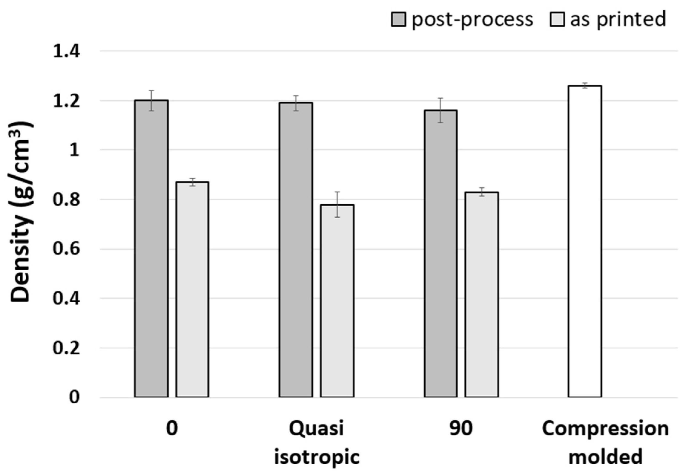
The density values are reported in
Figure 2. As can be seen, there was a remarkable density increase from the as-printed specimens to the post-processed ones. In fact, after the post-processing treatment, the density reached almost the same value as the compression-molded specimens, i.e., 1.26 g/cm
3. This gave evidence that most of the porosity was eliminated by the post-processing procedure.
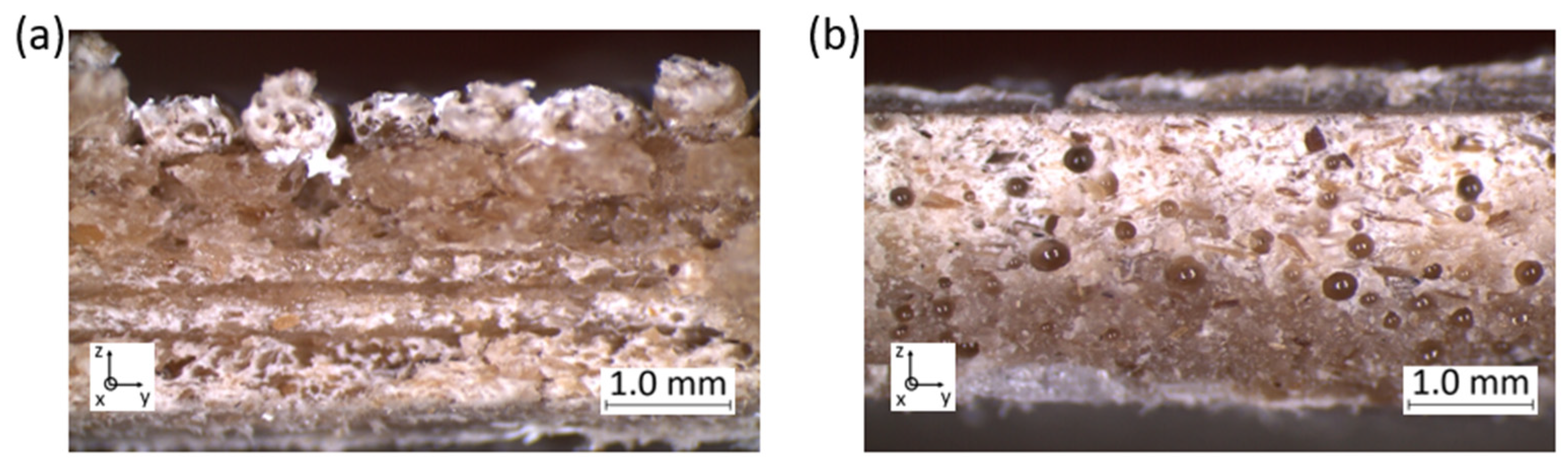
Void reduction is also clearly visible in
Figure 3, where the fracture surface of a symmetric and balanced printed specimen is pictured before and after the post-processing procedure. Porosity was quite evident, as shown in
Figure 3a, where voids were visible in between the beads and even within the single beads. Voids were indeed also still present in the post-processed sample, but they were mainly located in the middle part of the specimen cross section, and the deposited beads were no longer recognizable. Moreover, in the post-processed materials, the voids were mainly of a globular shape, while the porosity that could be seen in the as-printed sample was mostly located in the top layer.
By comparing
Figure 3a with
Figure 3b, a further aspect that can be noticed is that while in the pre-treated sample the stratification was recognizable, the different layers were not identifiable anymore in the post-processed sample. As a consequence of the porosity reduction and applied compaction, a thickness reduction was also well evident, as shown in
Figure 3b.
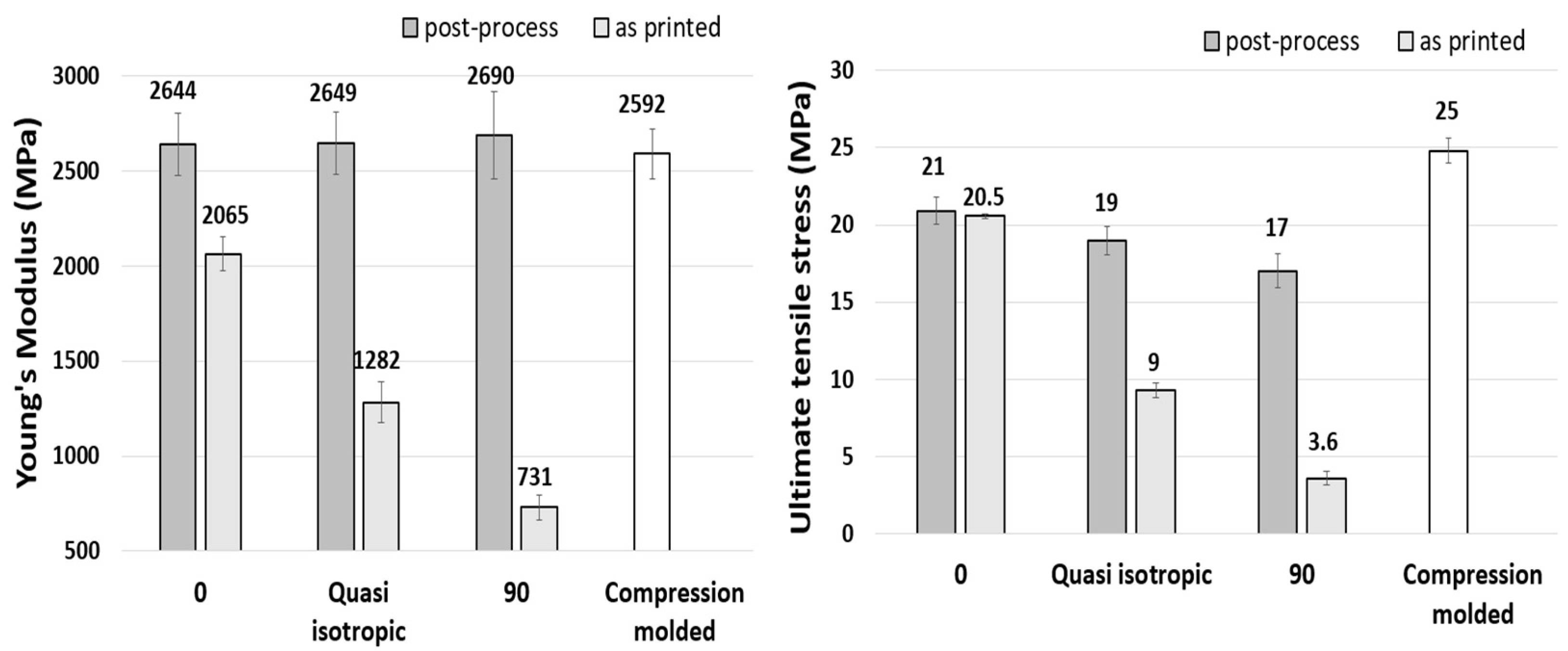
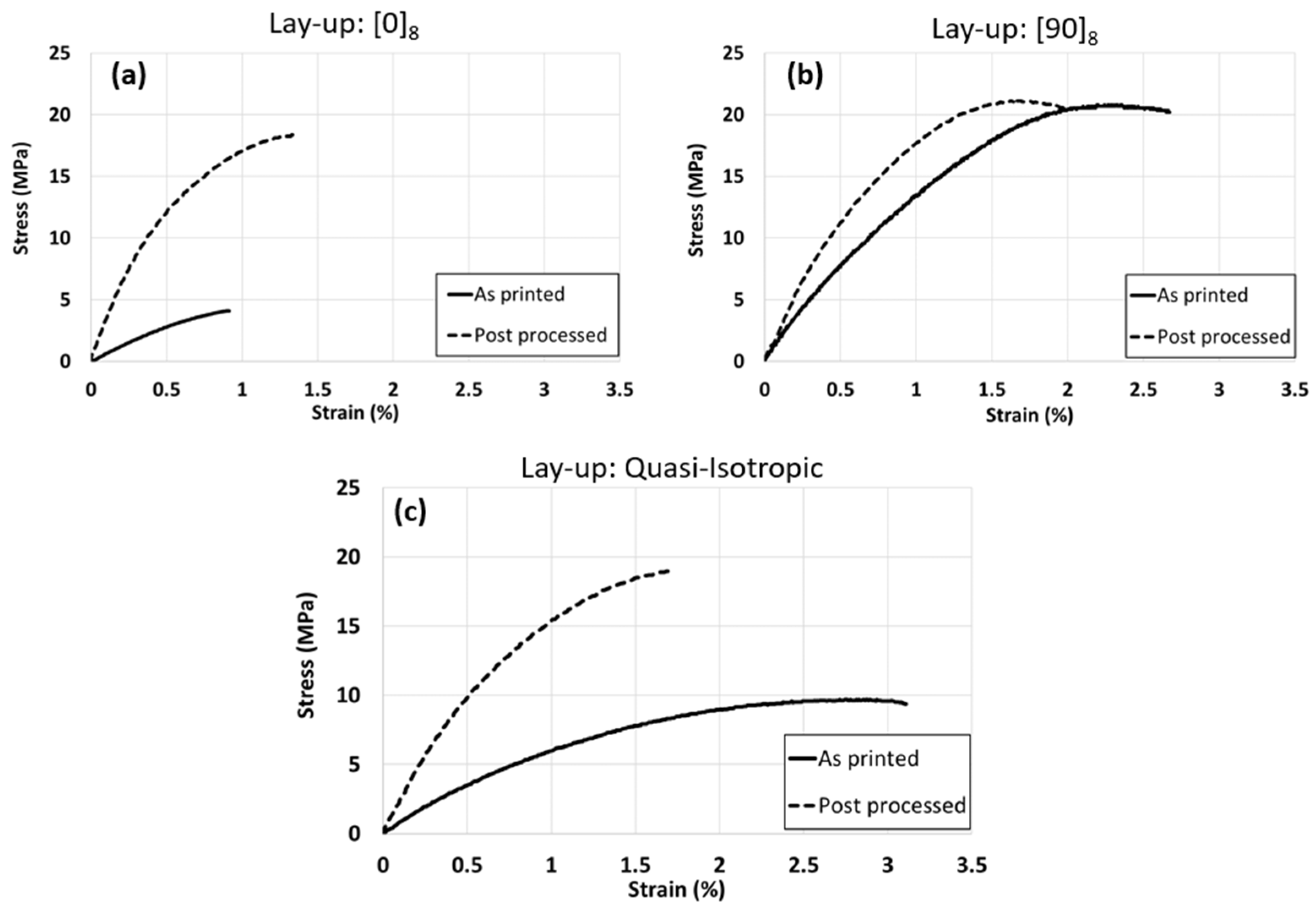
The results of the mechanical properties in terms of tension are shown in
Figure 4. Considering first the specimens that were not treated, all the types of samples obtained with the FFF technique had lower properties than those obtained by compression molding. Moreover, among the 3D-printed samples, the longitudinal specimens (i.e., [0°]
8) had the highest properties, followed by the quasi-isotropic specimens, while the transverse specimens (i.e., [90°]
8) had the lowest properties. This was not surprising, since, in the longitudinal samples, the effect of the bonding force between the layers and deposed beads was minimized, and the stiffness and strength were mostly dependent on the filament properties. Of course, in the other directions, the interlayer properties became increasingly important. This resulted in a remarkable anisotropy of the specimens, which is evident from
Figure 4. Despite this being generally true for all FFF-3D-printed materials, it was particularly the case in the case of the short-fiber-reinforced materials, since the fibers were laid parallel to the deposition direction of the extruder. However, the quasi-isotropic specimens possessed intermediate properties due to the orientation of their various layers.
Interestingly, the thermomechanical treatment had a profound effect on both the stiffness and strength, as can be seen in the same
Figure 4. The increase in these properties was highly dependent on the type of specimen. In particular, the strength and stiffness of the [90°]
8 and quasi-isotropic materials increased remarkably with respect to the pre-treated specimens, while the increase for the longitudinal specimen was more limited. Indeed, the results for the transversely loaded specimens showed an increase in stiffness and ultimate tensile strength of about 3.5 and 4.5 times the same values before post-processing. In the relevant literature concerning annealing, it was found that stiffness did improve after treatment, but the increase amounted to around 2–3 times the initial value [
11,
12,
13], while strength could increase by a factor of 2 [
14]. Analogous results were also obtained in [
15].
As a further noteworthy result, the mechanical properties of the various post-processed specimens tended to equal each other independently of the specimen type or the loading direction, indicating that the material became more isotropic after the treatment. This is clearly shown in
Figure 5, where the stress strain curves of the post-processed specimens are compared to one another. As a further confirmation, also shown in
Figure 5, the mechanical properties of the post-processed specimens were approximately the same as those of the compression-molded specimens.
This was in perfect agreement with the density results pictured in
Figure 2. Indeed, not all the voids in the post-processed materials were eliminated; therefore, the compression-molded samples presented higher mechanical properties. The improvement in the mechanical properties mostly came from the change in shape of the voids. Although voids were even present in the post-processed samples, these had a less dangerous shape, and in fact, in the transversely loaded specimens, the highest improvement was in terms of strength, since spheroidal voids have a lower stress concentration factor.
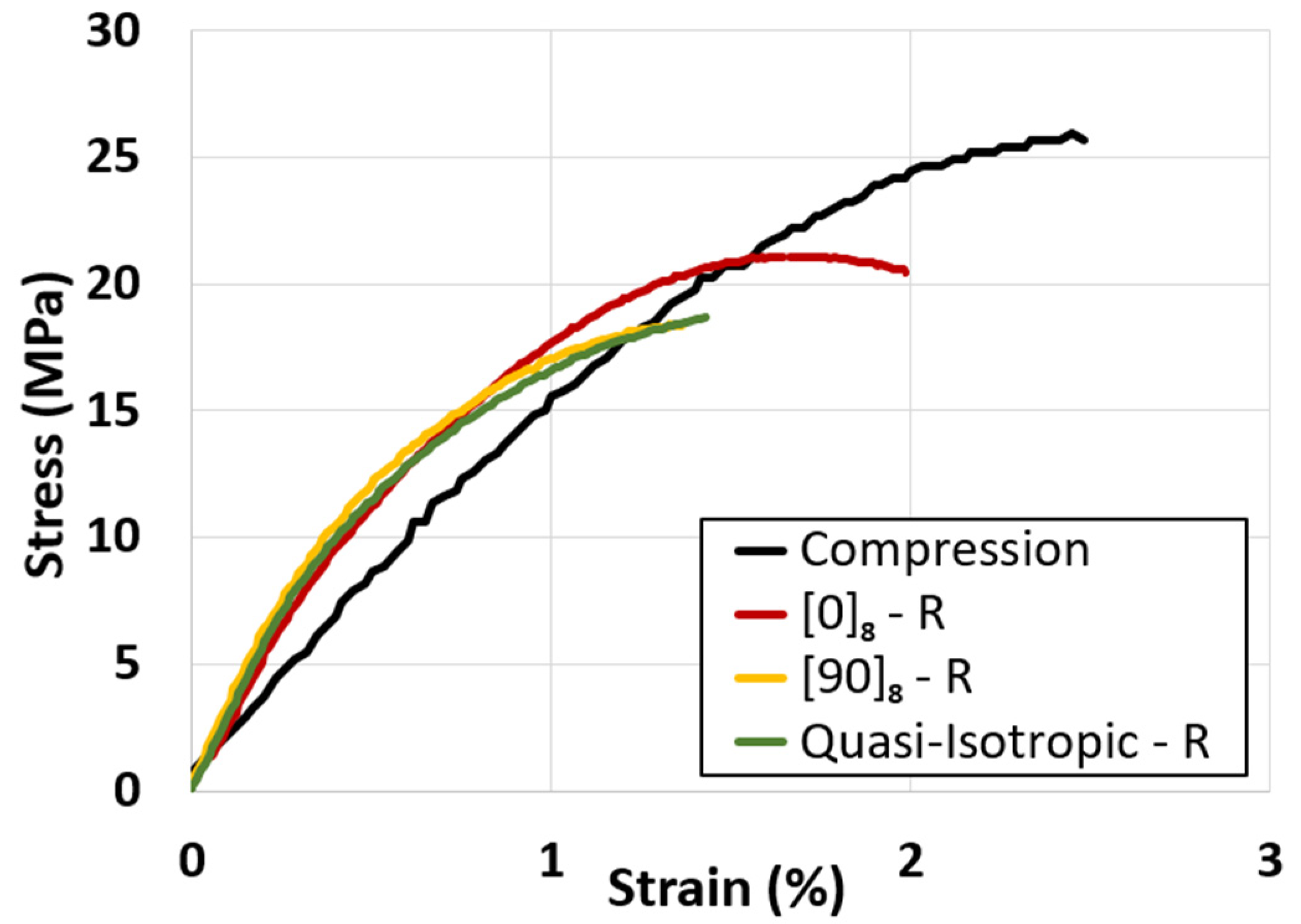
Together with the increase in the ultimate tensile strength and stiffness, it was also rather evident that such an improvement occurred at the expense of toughness, since the ultimate tensile strain became smaller after remelting under compaction. This is shown in
Figure 6. The material was rather brittle anyway, as in the best case the ultimate strain barely exceeded 3% for the pre-treated samples, while for the post-treated specimens it was reduced down to 1.5–2%. The reason for this behavior is rather difficult to explain precisely, although it is quite reasonable that the remelting procedure could increase PLA crystallinity, which may have given rise to a decrease in the ultimate tensile strain.
In order to have a better idea of the tensile behavior of the post-processed material, the graph in
Figure 6 shows the stress–strain diagram of the post-processed and compression-molded samples. The latter clearly had the highest stress and strain at breaking. All the specimens after post-treatment tended to lay upon a single curve, regardless of the raster infill orientation. This basically confirmed that the post-treated material became more isotropic.
4. Conclusions
In general, 3D-printed parts made with the FFF technique have lower mechanical properties than those made by injection molding due to the nature of the process. A 3D-printed part has several drawbacks; in fact, it is generally anisotropic, contains voids, and has low-quality bonding between its different layers. A novel post-processing method that consisted of melting and compaction in a granular mold was proposed in this article to reduce these problems. It exploited the melting of the material to allow intermolecular diffusion, it reduced the air gaps present in the microstructure of the 3D-printed part thanks to the applied pressure, and increased the interlayer bonding, thus decreasing the anisotropy.
The influence of this novel method was investigated based on tensile properties. Indeed, after this post-processing, the mechanical properties of the lay-ups increased, especially for the specimens loaded in the transverse direction. In this case, Young’s modulus and the ultimate tensile strength increased by about 3.5 and 4.5 times with respect to the initial value, respectively. The result was that the mechanical properties of the transversely loaded specimens reached the values of those loaded in the longitudinal direction, thus determining a more isotropic mechanical response.
This result was very interesting because, in the case of fiber-reinforced materials, a strongly anisotropic behavior was expected as the fibers are inevitably aligned in the deposition direction, thus the post-processing was particularly useful. Moreover, if the fibers are of a ligno-cellulosic origin, such as those used in the present article, porosity due to material hygroscopicity occurs in spite of the extensive drying of the filament. In such a case, post-processing is particularly beneficial as it is also effective in reducing this type of porosity.
However, this process had limitations, such as dimensional distortion and a reduction in the thickness of the samples proportional to the eliminated voids. Further investigations are needed both at the method and printing level. Regarding the method, different pressures, permanence times, and temperatures could be investigated. Conversely, at the printing level, it would be interesting to investigate the enhancement of the mechanical properties varying not only the raster infill but also other parameters such as the extruder temperature and printing speed. Nevertheless, this can be considered a promising starting point for the development of a new post-processing method.


