
In Vivo Performance of Magnesium Alloy LX41 in a Rat Model

 , , and
Abstract
:
1. Introduction
2. Material and Methods
2.1. Material Development and Sterilization
2.1.1. Production of the Material
2.1.2. Thermomechanical Treatment
2.1.3. Microstructure and Texture Characterization
2.2. Ethics Statement
2.3. Animals, Anaesthesia and Analgesia
2.4. Transcortical Implantation
2.5. In Vivo Low to Medium Resolution Micro-Computed Tomography (µCT)
2.6. Computation of the Degradation Rate
2.7. Qualitative Histological Examination
2.8. Statistical Analysis
3. Results
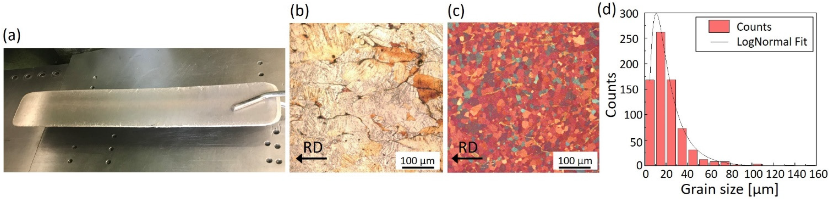
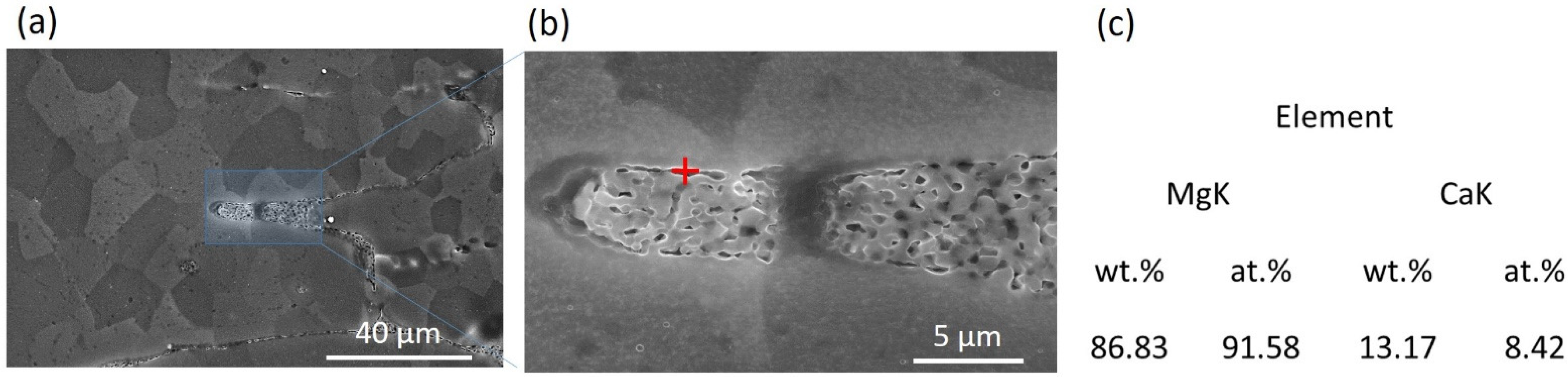
3.1. Microstructure
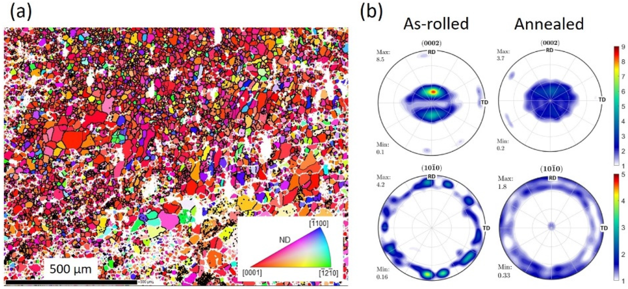
3.2. Texture
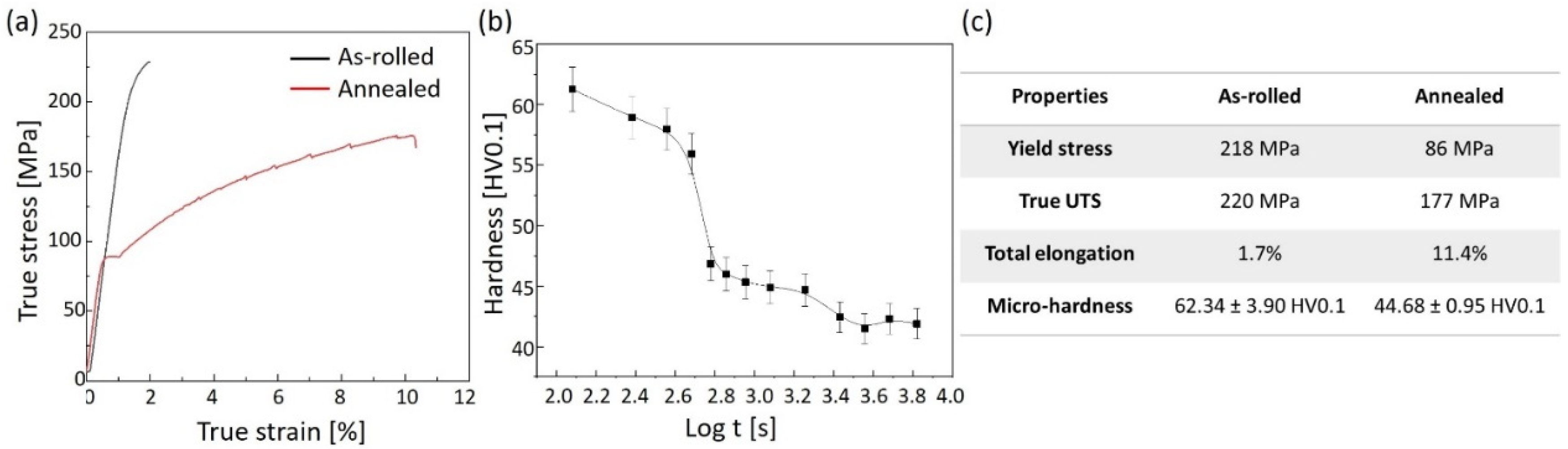
3.3. Mechanical Behaviour
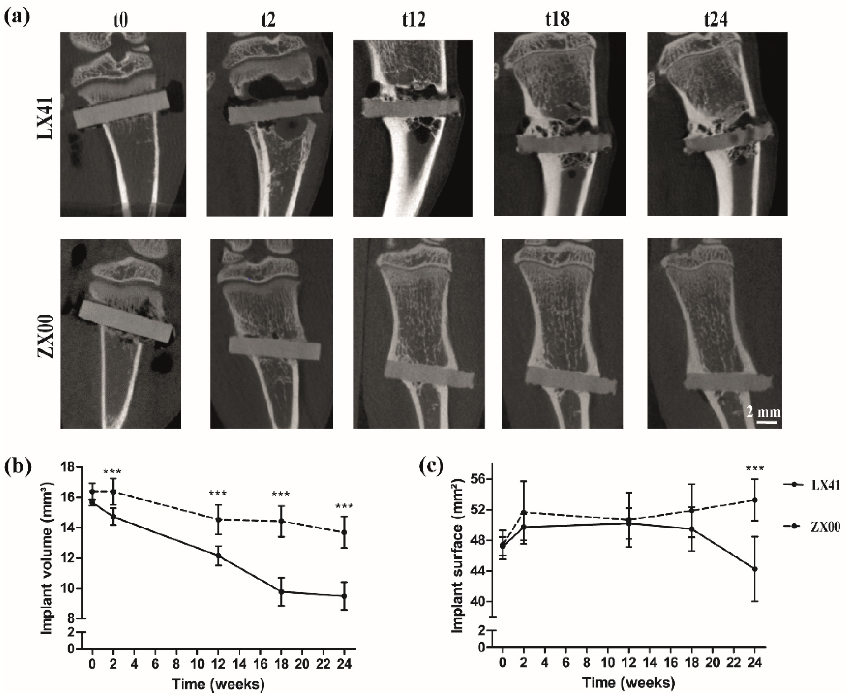
3.4. Implant Degradation as Measured by µCT Imaging
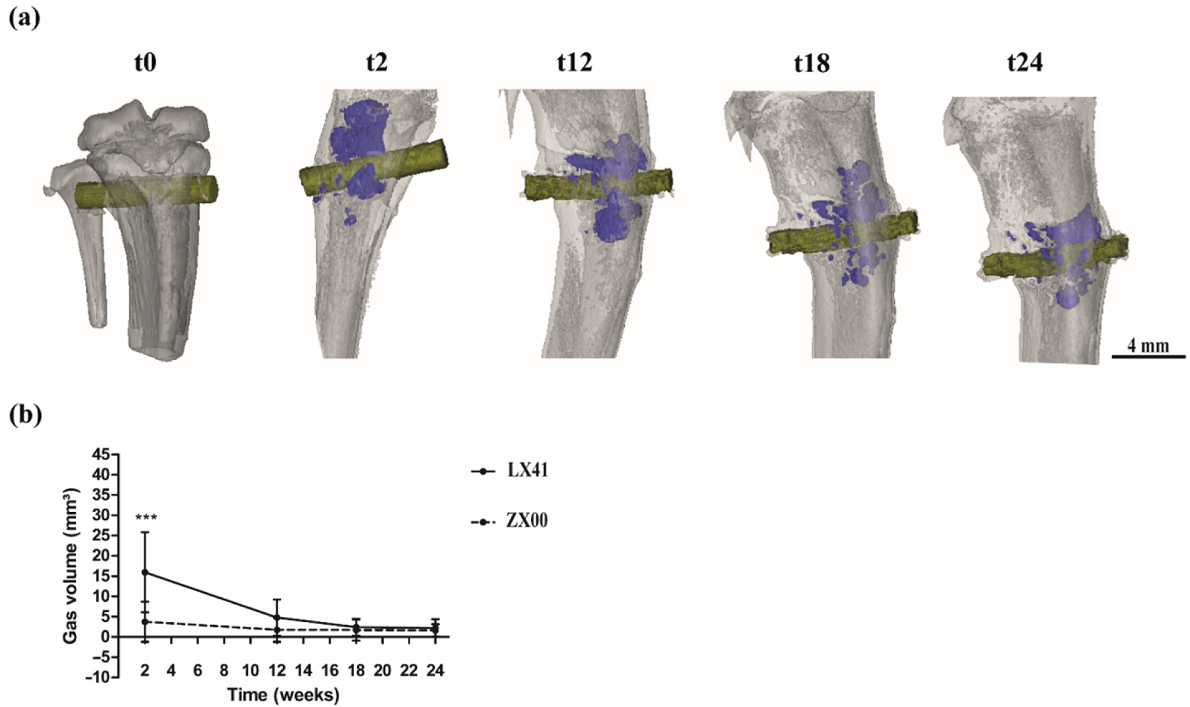
3.5. Increase of the Hydrogen Gas Formation Two Weeks after LX41 Implantation
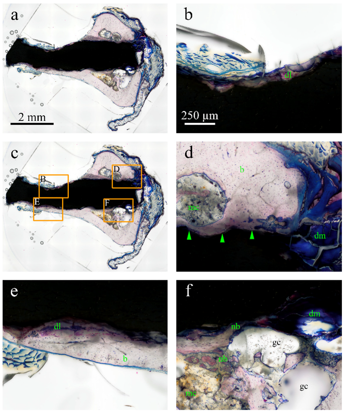
3.6. Histological Evaluation of Osseointegration and Gas Formation for LX41 Pins
4. Discussion
5. Conclusions
Supplementary Materials
Author Contributions
Funding
Data Availability Statement
Acknowledgments
Conflicts of Interest
References
- Holweg, P.; Herber, V.; Ornig, M.; Hohenberger, G.; Donohue, N.; Puchwein, P.; Leithner, A.; Seibert, F. A lean bioabsorbable magnesium-zinc-calcium alloy ZX00 used for operative treatment of medial malleolus fractures. Bone Jt. Res. 2020, 9, 477–483. [Google Scholar] [CrossRef]
- Herber, V.; Labmayr, V.; Sommer, N.G.; Marek, R.; Wittig, U.; Leithner, A.; Seibert, F.; Holweg, P. Can Hardware Removal be Avoided Using Bioresorbable Mg-Zn-Ca Screws After Medial Malleolar Fracture Fixation? Mid-Term Results of a First-In-Human Study. Injury 2022, 53, 1283–1288. [Google Scholar] [CrossRef]
- Witte, F.; Eliezer, A. Biodegradable Metals. In Degradation of Implant Materials; Eliaz, N., Ed.; Springer: New York, NY, USA, 2012; pp. 93–109. [Google Scholar] [CrossRef]
- Lin, X.; Saijilafu, X.; Wu, K.; Chen, J.; Tan, L.; Witte, F.; Yang, H.; Mantovani, D.; Zhou, H.; Liang, C.; et al. Biodegradable Mg-based alloys: Biological implications and restorative opportunities. Int. Mater. Rev. 2022, 1–39. [Google Scholar] [CrossRef]
- Kirkland, N.T.; Lespagnol, J.; Birbilis, N.; Staiger, M.P. A survey of bio-corrosion rates of magnesium alloys. Corros. Sci. 2010, 52, 287–291. [Google Scholar] [CrossRef]
- Virtanen, S. Biodegradable Mg and Mg alloys: Corrosion and biocompatibility. Mater. Sci. Eng. B 2011, 176, 1600–1608. [Google Scholar] [CrossRef]
- Tsakiris, V.; Tardei, C.; Clicinschi, F.M. Biodegradable Mg alloys for orthopedic implants–A review. J. Magnes. Alloy. 2021, 9, 1884–1905. [Google Scholar] [CrossRef]
- Yu, W.; Chen, D.; Ding, Z.; Qiu, M.; Zhang, Z.; Shen, J.; Zhang, X.; Zhang, S.; He, Y.; Shi, Z. Synergistic effect of a biodegradable Mg–Zn alloy on osteogenic activity and anti-biofilm ability: An in vitro and in vivo study. RSC Adv. 2016, 6, 45219–45230. [Google Scholar] [CrossRef]
- Chen, Y.; Dou, J.; Yu, H.; Chen, C. Degradable magnesium-based alloys for biomedical applications: The role of critical alloying elements. J. Biomater. Appl. 2019, 33, 1348–1372. [Google Scholar] [CrossRef]
- Witte, F. The history of biodegradable magnesium implants: A review. Acta Biomater. 2010, 6, 1680–1692. [Google Scholar] [CrossRef]
- Okuma, T. Magnesium and bone strength. Nutrition 2001, 17, 679–680. [Google Scholar] [CrossRef]
- Kamrani, S.; Fleck, C. Biodegradable magnesium alloys as temporary orthopaedic implants: A review. Biometals 2019, 32, 185–193. [Google Scholar] [CrossRef]
- Kim, Y.K.; Lee, K.B.; Kim, S.Y.; Bode, K.; Jang, Y.S.; Kwon, T.Y.; Jeon, M.H.; Lee, M.H. Gas formation and biological effects of biodegradable magnesium in a preclinical and clinical observation. Sci. Technol. Adv. Mater. 2018, 19, 324–335. [Google Scholar] [CrossRef] [Green Version]
- Nene, S.S.; Kashyap, B.P.; Prabhu, N.; Estrin, Y.; Al-Samman, T. Microstructure refinement and its effect on specific strength and bio-corrosion resistance in ultralight Mg–4Li–1Ca (LC41) alloy by hot rolling. J. Alloys Compd. 2014, 615, 501–506. [Google Scholar] [CrossRef]
- Estrin, Y.; Nene, S.S.; Kashyap, B.P.; Prabhu, N.; Al-Samman, T. New hot rolled Mg-4Li-1Ca alloy: A potential candidate for automotive and biodegradable implant applications. Mater. Lett. 2016, 173, 252–256. [Google Scholar] [CrossRef]
- Nene, S.S.; Estrin, Y.; Kashyap, B.P.; Prabhu, N.; Al-Samman, T.; Luthringer, B.J.; Willumeit, R. Towards microstructure-cytocompatibility relationship in ultralight Mg-4Li-1Ca (LX41) alloy for degradable implant applications. BioNanoMaterials 2016, 17, 103–111. [Google Scholar] [CrossRef]
- McIntyre, R.S.; Berk, M.; Brietzke, E.; Goldstein, B.I.; López-Jaramillo, C.; Kessing, L.V.; Malhi, G.S.; Nierenberg, A.A.; Rosenblat, J.D.; Majeed, A.; et al. Bipolar disorders. Lancet 2020, 396, 1841–1856. [Google Scholar] [CrossRef]
- Zhang, J.; Cai, L.; Tang, L.; Zhang, X.; Yang, L.; Zheng, K.; He, A.; Boccaccini, A.R.; Wei, J.; Zhao, J. Highly dispersed lithium doped mesoporous silica nanospheres regulating adhesion, proliferation, morphology, ALP activity and osteogenesis related gene expressions of BMSCs. Colloids Surf. B Biointerfaces 2018, 170, 563–571. [Google Scholar] [CrossRef]
- Nam, D.; Balasuberamaniam, P.; Milner, K.; Kunz, M.; Vachhani, K.; Kiss, A.; Whyne, C. Lithium for Fracture Treatment (LiFT): A double-blind randomised control trial protocol. BMJ Open 2020, 10, e031545. [Google Scholar] [CrossRef] [Green Version]
- Pan, C.; Chen, L.; Wu, R.; Shan, H.; Zhou, Z.; Lin, Y.; Yu, X.; Yan, L.; Wu, C. Correction: Lithium-containing biomaterials inhibit osteoclastogenesis of macrophages in vitro and osteolysis in vivo. J. Mater. Chem. B 2019, 7, 2566. [Google Scholar] [CrossRef]
- Ma, Y.; Li, Y.; Hao, J.; Ma, B.; Di, T.; Dong, H. Evaluation of the degradation, biocompatibility and osteogenesis behavior of lithium-doped calcium polyphosphate for bone tissue engineering. Bio-Med. Mater. Eng. 2019, 30, 23–36. [Google Scholar] [CrossRef]
- Luo, Y.; Li, D.; Zhao, J.; Yang, Z.; Kang, P. In vivo evaluation of porous lithium-doped hydroxyapatite scaffolds for the treatment of bone defect. Bio-Med. Mater. Eng. 2018, 29, 699–721. [Google Scholar] [CrossRef]
- Hu, X.; Wang, Z.; Shi, J.; Guo, X.; Wang, L.; Ping, Z.; Tao, Y.; Yang, H.; Zhou, J.; Xu, Y.; et al. Lithium chloride inhibits titanium particle-induced osteoclastogenesis by inhibiting the NF-κB pathway. Oncotarget 2017, 8, 83949–83961. [Google Scholar] [CrossRef] [Green Version]
- Sommer, N.G.; Hirzberger, D.; Paar, L.; Berger, L.; Ćwieka, H.; Schwarze, U.Y.; Herber, V.; Okutan, B.; Bodey, A.J.; Willumeit-Römer, R.; et al. Implant degradation of low-alloyed Mg–Zn–Ca in osteoporotic, old and juvenile rats. Acta Biomater. 2022, 147, 427–438. [Google Scholar] [CrossRef]
- Lackó, J.; Géza, L. A simple differential staining method for semi-thin sections of ossifying cartilage and bone tissues embedded in epoxy resin. Mikroskopie 1975, 31, 1–4. [Google Scholar]
- Bachmann, F.; Hielscher, R.; Schaeben, H. Texture Analysis with MTEX–Free and Open Source Software Toolbox. Solid State Phenom. 2010, 160, 63–68. [Google Scholar] [CrossRef] [Green Version]
- Grün, N.G.; Holweg, P.; TangI, S.; Eichler, J.; Berger, L.; van den Beucken, J.J.J.P.; Löffler, J.F.; Klestil, T.; Weinberg, A.M. Comparison of a resorbable magnesium implant in small and large growing-animal models. Acta Biomater. 2018, 78, 378–386. [Google Scholar] [CrossRef]
- Kraus, T.; Fischerauer, S.F.; Hänzi, A.C.; Uggowitzer, P.J.; Löffler, J.F.; Weinberg, A.M. Magnesium alloys for temporary implants in osteosynthesis: In vivo studies of their degradation and interaction with bone. Acta Biomater. 2012, 8, 1230–1238. [Google Scholar] [CrossRef]
- Donath, K. Die Trenn-Dünnschliff-Technik zur Herstellung Histologischer Präparate von Nicht Schneidbaren Geweben und Materialien: Apparate- und Methodenbeschreibung; EXAKT-Kulzer-Druckschraube: Wehrheim, Germany, 1988. [Google Scholar]
- Robson, J.D.; Henry, D.T.; Davis, B. Particle effects on recrystallization in magnesium–manganese alloys: Particle-stimulated nucleation. Acta Mater. 2009, 57, 2739–2747. [Google Scholar] [CrossRef]
- Ball, E.A.; Prangnell, P.B. Tensile-compressive yield asymmetries in high strength wrought magnesium alloys. Scr. Metall. Et Mater. 1994, 31, 2. [Google Scholar] [CrossRef]
- Al-Samman, T. Modification of texture and microstructure of magnesium alloy extrusions by particle-stimulated recrystallization. Mater. Sci. Eng. A 2013, 560, 561–566. [Google Scholar] [CrossRef]
- Kubin, L.P.; Estrin, Y. Evolution of dislocation densities and the critical conditions for the Portevin-Le Châtelier effect. Acta Metall. Et Mater. 1990, 38, 697–708. [Google Scholar] [CrossRef]
- Jin, Y.; Blawert, C.; Yang, H.; Wiese, B.; Feyerabend, F.; Bohlen, J.; Mei, D.; Deng, M.; Campos, M.S.; Scharnagl, N. Microstructure-corrosion behaviour relationship of micro-alloyed Mg-0.5 Zn alloy with the addition of Ca, Sr, Ag, In and Cu. Mater. Des. 2020, 195, 108980. [Google Scholar] [CrossRef]
- Ben-Hamu, G.; Eliezer, D.; Kaya, A.; Na, Y.G.; Shin, K.S. Microstructure and corrosion behavior of Mg–Zn–Ag alloys. Mater. Sci. Eng. A 2006, 435, 579–587. [Google Scholar] [CrossRef]
- Myrissa, A.; Agha, N.A.; Lu, Y.; Martinelli, E.; Eichler, J.; Szakacs, G.; Kleinhans, C.; Willumeit-Römer, R.; Schäfer, U.; Weinberg, A.M. In vitro and in vivo comparison of binary Mg alloys and pure Mg. Mater. Sci. Eng. C 2016, 61, 865–874. [Google Scholar] [CrossRef]
- Zhao, D.; Witte, F.; Lu, F.; Wang, J.; Li, J.; Qin, L. Current status on clinical applications of magnesium-based orthopaedic implants: A review from clinical translational perspective. Biomaterials 2017, 112, 287–302. [Google Scholar] [CrossRef]
- Li, Z.; Gu, X.; Lou, S.; Zheng, Y. The development of binary Mg–Ca alloys for use as biodegradable materials within bone. Biomaterials 2008, 29, 1329–1344. [Google Scholar] [CrossRef]
- Zeng, R.C.; Sun, L.; Zheng, Y.F.; Cui, H.Z.; Han, E.H. Corrosion and characterisation of dual phase Mg–Li–Ca alloy in Hank’s solution: The influence of microstructural features. Corros. Sci. 2014, 79, 69–82. [Google Scholar] [CrossRef]
- Brunner, P.; Brumbauer, F.; Steyskal, E.M.; Renk, O.; Weinberg, A.M.; Schroettner, H.; Würschum, R. Influence of high-pressure torsion deformation on the corrosion behaviour of a bioresorbable Mg-based alloy studied by positron annihilation. Biomater. Sci. 2019, 11, 4099–4109. [Google Scholar] [CrossRef]
- Witte, F.; Kaese, V.; Haferkamp, H.; Switzer, E.; Meyer-Lindenberg, A.; Wirth, C.J.; Windhagen, H. In vivo corrosion of four magnesium alloys and the associated bone response. Biomaterials 2005, 26, 3557–3563. [Google Scholar] [CrossRef]
- Kraus, T.; Fischerauer, S.; Treichler, S.; Martinelli, E.; Eichler, J.; Myrissa, A.; Zötsch, S.; Uggowitzer, P.J.; Löffler, J.F.; Weinberg, A.M. The influence of biodegradable magnesium implants on the growth plate. Acta Biomater. 2018, 66, 109–117. [Google Scholar] [CrossRef]
- Tie, D.; Feyerabend, F.; Hort, N.; Hoeche, D.; Kainer, K.U.; Willumeit, R.; Mueller, W.D. In vitro mechanical and corrosion properties of biodegradable Mg–Ag alloys. Mater. Corros.. 2014, 65, 569–576. [Google Scholar] [CrossRef]
- Makkar, P.; Sarkar, S.K.; Padalhin, A.R.; Moon, B.G.; Lee, Y.S.; Lee, B.T. In vitro and in vivo assessment of biomedical Mg–Ca alloys for bone implant applications. J. Appl. Biomater. Funct. Mater. 2018, 16, 126–136. [Google Scholar] [CrossRef] [PubMed] [Green Version]
- Cheng, M.Q.; Wahafu, T.; Jiang, G.F.; Liu, W.; Qiao, Y.Q.; Peng, X.C.; Cheng, T.; Zhang, X.; He, G.; Liu, X. A novel open-porous magnesium scaffold with controllable microstructures and properties for bone regeneration. Sci. Rep. 2016, 6, 24134. [Google Scholar] [CrossRef] [PubMed]


Publisher’s Note: MDPI stays neutral with regard to jurisdictional claims in published maps and institutional affiliations. |
© 2022 by the authors. Licensee MDPI, Basel, Switzerland. This article is an open access article distributed under the terms and conditions of the Creative Commons Attribution (CC BY) license (https://creativecommons.org/licenses/by/4.0/).
Share and Cite
Sommer, N.G.; Gieringer, S.; Schwarze, U.Y.; Weinberg, A.-M.; Al-Samman, T.; Estrin, Y. In Vivo Performance of Magnesium Alloy LX41 in a Rat Model. Processes 2022, 10, 2222. https://doi.org/10.3390/pr10112222
Sommer NG, Gieringer S, Schwarze UY, Weinberg A-M, Al-Samman T, Estrin Y. In Vivo Performance of Magnesium Alloy LX41 in a Rat Model. Processes. 2022; 10(11):2222. https://doi.org/10.3390/pr10112222
Chicago/Turabian StyleSommer, Nicole G., Sandra Gieringer, Uwe Y. Schwarze, Annelie-M. Weinberg, Talal Al-Samman, and Yuri Estrin. 2022. "In Vivo Performance of Magnesium Alloy LX41 in a Rat Model" Processes 10, no. 11: 2222. https://doi.org/10.3390/pr10112222