Article

Degradation of Hydroquinone Coupled with Energy Generation through Microbial Fuel Cells Energized by Organic Waste

by
Tasnim Aisya Mahmuelee Torlaema
1,
Mohamad Nasir Mohamad Ibrahim
1,*,
Akil Ahmad
2,*,
Claudia Guerrero-Barajas
3,
Mohammed B. Alshammari
2,
Sang-Eun Oh
4 and
Fida Hussain
5,*
1
Materials Technology Research Group (MaTRec), School of Chemical Sciences, Universiti Sains Malaysia, Minden 11800, Penang, Malaysia
2
Department of Chemistry, College of Science and Humanities in Al-Kharj, Prince Sattam bin Abdulaziz University, Al-Kharj 11942, Saudi Arabia
3
Laboratorio de Biotecnología Ambiental, Departamento de Bioprocesos, Unidad Profesional Interdisciplinaria de Biotecnología, Instituto Politécnico Nacional, Av. Acueducto s/n, Col. Barrio La Laguna Ticomán, Mexico City 07340, Mexico
4
Department of Biological Environment, Kangwon National University, Chuncheon-si 24398, Korea
5
Research Institute for Advanced Industrial Technology, College of Science and Technology, Korea University, Sejong 30019, Korea
*
Authors to whom correspondence should be addressed.
Processes 2022, 10(10), 2099; https://doi.org/10.3390/pr10102099
Submission received: 14 September 2022 / Revised: 2 October 2022 / Accepted: 13 October 2022 / Published: 17 October 2022

Abstract

:
Microbial fuel cell (MFC) technology has captured the scientific community’s attention in recent years owing to its ability to directly transform organic waste into electricity through electrochemical processes. Currently, MFC systems faces a number of barriers, with one of the most significant being the lack of organic substrate to provide enough energy for bacterial growth and activity. In the current work, rotten rice was utilized as an organic substrate to boost bacterial activity to produce more energy and break down the organic pollutant hydroquinone in an effort to improve the performance of MFCs. There are only a few studies that considered the waste as an organic substrate and simultaneously degraded the organic pollutant vis-à-vis MFCs. The oxidation of glucose derived from rotten rice generated electrons that were transported to the anode surface and subsequently flowed through an external circuit to the cathode, where they were used to degrade the organic pollutant hydroquinone. The results were consistent with the MFC operation, where the 168-mV voltage was generated over the course of 29 days with a 1000 Ω external resistance. The maximum power and current densities were 1.068 mW/m2 and 123.684 mA/m2, respectively. The hydroquinone degradation was of 68%. For the degradation of organic pollutants and the production of energy, conductive pili-type bacteria such as Lacticaseibacillus, Pediococcus acidilactici and Secundilactobacillus silagincola species were identified during biological characterization. Future recommendations and concluding remarks are also included.

1. Introduction

Microbial fuel cell (MFC) technology has captivated the scientific community in recent years due to its potential to convert organic waste directly into power via microbially catalyzed anodic and cathodic electrochemical processes [1]. There may be more bioenergy from microbial electricity production in the future because MFCs can generate electricity from a lot of different types of waste, as well as from renewable biomass [2]. MFC systems are a bioelectrochemical technology that directly converts organic substrates into electrical energy using the power of respiring microorganisms. At its core, the MFC is a fuel cell that converts chemical energy into electricity through oxidation reduction reactions and simultaneously removes the pollutant from wastewater [3]. When compared to conventional fuel cells and enzymatic fuel cells, MFCs present significant benefits. As a source of fuel generation, a wide range of organic and inorganic substances, such as organic waste, seafood waste and soil sediments, may be used [4,5]. Due to the direct or single-step conversion of substrate energy to electricity, such devices can achieve high conversion efficiencies. Unlike traditional fuel cells, MFCs may operate at room temperature and pressure. Other technologies, such as anaerobic digesters and aerated lagoons, have been outperformed by MFCs [6]. Huang et al. [7] reported MFCs as a possible long-term solution to satisfy rising energy demands, particularly when organic biomasses are used as substrates. In Malaysia, rice is the most extensively farmed crop and is consumed as a daily meal, therefore, there is a significant amount of waste from it. The quantity of rotten rice in Malaysia alone is projected to be able to feed 12 million people three times a day, and the typical Malaysian throws away 1.64 kg per day, compared to the global average of 1.2 kg [8]. Rice is composed of several distinct components, the most important of which is starch, which accounts for 80–90% of the total. Starch is a complex carbohydrate composed of several bits of glucose, a form of sugar [9]. Rice is a good organic substrate for MFCs due to its high glucose content, which will be utilized as food for bacteria in the anaerobic process, whereby the anode’s active biocatalyst oxidizes the organic substrates, creating electrons and protons. Protons are transported to the cathode chamber, whereas electrons are transported via the external circuit. A voltage drop and an electrical current are generated, converting chemical energy into electrical power. In the cathode chamber, protons and electrons react while oxygen is reduced to water [10]. The high generation of electrons is a sign of the high oxidation rate of the substrate, which means that the bacterial community is working efficiently. Thus, the pollutant degradation process will increase during operation. As described earlier, MFCs are also used for water treatment. Though current and power yields are currently low, it is expected that as the technology and knowledge of these unique systems improve, the amount of electric current that can be extracted from these systems will skyrocket, providing a long-term solution for directly degrading organic pollutants in wastewater [11]. Many industrial wastewater effluents include organic contaminants such as phenol, benzaldehyde, and hydroquinone that must be removed as soon as possible [12]. There is no study available on hydroquinone degradation by MFCs. It is a dihydroxy benzene (DHB) isomer, which means it is a simple electroactive compound [13]. Hydroquinone, on the other hand, is a hazardous compound even at low concentrations. As a result, it is regarded as a visible pollutant in pharmaceutical, nutritional, and environmental goods [14,15,16]. MFCs are the best technique for degrading hydroquinone. This is the first-time in which hydroquinone biodegradation in MFCs has been shown to occur in the presence of rotten rice, which makes a novel contribution to the field. The use of this waste as a substrate for MFC technology will lead to a novel approach to degrading organic pollutants. The organic pollutant (hydroquinone) also serves as an electron donor along with rotten rice, which will increase the energy efficiency. The study was limited to the remediation of hydroquinone, an organic contaminant that was injected into the local wastewater. The results of different electrochemical tests and biological characterizations have backed up the conclusions.

2. Experimental Details

2.1. Materials and Chemicals

The wastewater was collected from a local lake while rotten rice waste was obtained from the Bakti café at Universiti Sains Malaysia. Commercial graphite rods (FUDA Lead, NY, USA), distilled water, and hydroquinone (R&M Chemical, Bhopal, India) were some of the materials that were used in this study.

2.2. Source of Inoculation

The collected wastewater was treated with 10 ppm of hazardous organic pollutants to produce an organic pollutant-based wastewater. In this study, 800 g of rotten rice waste material was employed as a bacterial organic substrate, and both of the organic pollutant--based wastewater was labelled as synthetic wastewater. A pH meter (EUTECH instrument-700; New York, NY, USA), a thermometer (GH, ZEAL LTD; London, UK), and an electrical meter (ECM) (Alpha-800 conductivity meter, Vernon Hills, IL, USA) were employed to determine the conductivity, pH, and temperature. Table 1 shows several physico-chemical parameters for lake wastewater and hydroquinone synthetic wastewater.

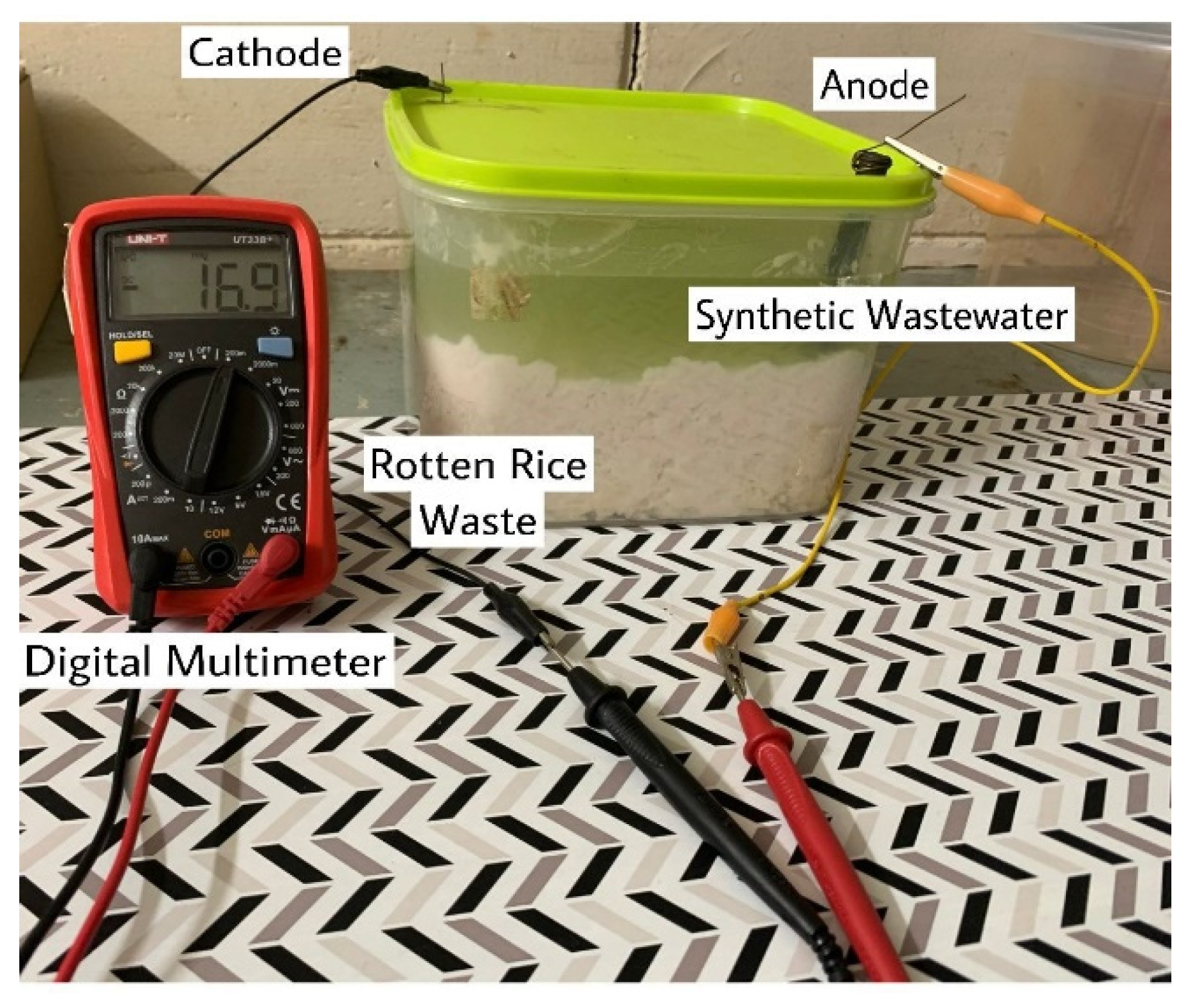
2.3. Preparation of MFC Set-Up

A single-chamber microbial fuel cell MFC was designed in this experiment to generate electricity and generate clean water from wastewater. For hydroquinone degradation, the MFC set-up was of 16.5 cm in height and 13.5 cm in diameter. The MFC had a total working volume of 3000 mL, this included 800 g of rotten rice that was placed with 900 mL of wastewater and 100 mL (10 ppm) of hydroquinone stock solution in the MFC. The MFC was then vertically inserted with commercial graphite rods whose dimensions were 11.5 cm × 1 cm (h × r) anode and 10 cm × 1 cm (h × r) cathode. The distance between the anode and cathode was of 17.0 cm. The electrodes were connected with a platinum wire and had an external resistance of 1000 Ω. The MFC was operated with rotten rice for 60 days at room temperatures ranging from 25 to 30 °C. Figure 1 depicts the MFC reactor designed for this research. To confirm that the data could be reproduced, the experiment was conducted three times.

2.4. MFC Electrochemical Test

Once every 24 h, a digital multimeter (UNI-T UT33A, China) was used to detect the voltage between the anode and the cathode, and Ohm’s law was utilized to convert the voltage to ampere (current). The Equations (1)–(4) below were used to figure out the power density (PD), current density (CD), and internal resistance.
V = IR
PD = V 2 RA
CD = I A
Internal   Resistance = [ E V V ] R
where, V is voltage output; A is cross-sectional area; I is current; R is internal resistance; and E is electromotive force. The electromotive measurement was performed using open circuit voltage (OCV). The internal resistance of the MFC was estimated from the slope of the polarization curve and a box with different resistances. The box had a range of 7000 Ω to 100 Ω.
On the electrode surface, the redox processes were examined by using cyclic voltammetry (CV, Model BAS Epsilon Version 1.4; West Lafayette, IN, USA). At the 10-day time intervals, the electrode surface was monitored at a 30 mV/s scanning rate with a potential range of +0.8 V to 0.8 V. Platinum wire and glassy carbon served as the electrode counter and working electrodes, respectively, with Ag/AgCl serving as the reference electrode. The electrode potential was used to determine the reference electrode.
The total of both anode and cathode data per unit area of the cathode and anode is described as the specific capacitance, Cp (F/g). In Equation (5), A is the area of the CV curve, m is the number of samples that were loaded into the CV instrument, k is the CV scan rate in mV/s, and V2-V1 is the CV potential range.
C P = A 2 mk   ( V 2 V 1 )
In a similar vein, the resistance effect of the anode toward voltage was investigated using electrochemical impedance spectroscopy (EIS; Gamry Reference 600; Warminster, PA, USA) at various points throughout time. The EIS study was performed in the operative mode of MFCs from a frequency range of 100,000 Hz to 0.1 Hz on days 10, 20, and 29. To avoid biofilm attachment and minimize disruption of the steady-state system, the amplitude of the alternating current (AC) was approximated at 1 mV [17].

2.5. Degradation Efficiency Calculation

Organic pollutant contents were examined using an ultraviolet visible (UV-Vis) light source by using a Shimadzu UV–Vis 2600 Kyoto, Japan Spectrophotometer, to determine removal performance. A sample of around 1 mL was taken from the hydroquinone MFC every 10 days after 20 days, diluted to 1 ppm, and the organic pollutant concentration was determined. Equation (6) was used to calculate the percentage of degradation efficiency where To was denoted as the initial concentration, and T as the final concentration.
Degradation   efficiency   % = T O T [ T O ] × 100

2.6. Biological Characterization

The biological characterization consisted of bacterium isolation and identification to determine the type of bacteria developed in the MFC. By using the serial dilution technique and plating bacteria with the streaking technique, pure bacterial cultures can be obtained. Serial dilution is the process of diluting a substance into a solution in steps with a consistent dilution ratio. One milliliter of sample is diluted in 99 mL of autoclaved distilled water, followed by six 9 mL of autoclaved distilled water. The diluted sample is then put over nutrient agar and allowed to sit for 72 h. The streak plate technique was used to isolate bacteria from a mixed population. By distributing the inoculum throughout the agar surface in this way, the bacteria were thinned out. Bacterial genes were created using the polymerase chain reaction (PCR) method. A forward primer and a reverse primer were used to amplify the genes. A cloning kit (TOPOTA, Invitrogen; Carlsbad, CA, USA) was used to clone the PCR-generated result. Bacterial strains were submitted to GenBank after DNA sequencing. The growth and stability of the biofilm and surface appearance were studied using scanning electron microscopy (SEM-Zeiss, DSM-960, Oberkochen, Germany). The SEM photos show bacterial growth on the anode’s surface after it was subjected to organic pollutant concentration reduction from synthetic wastewater. At the end of the process, the biofilm-anode electrode’s energy dispersive X-ray (EDX) was taken to look into how the hazardous organic pollutant affected the biofilm.

3. Result and Discussion

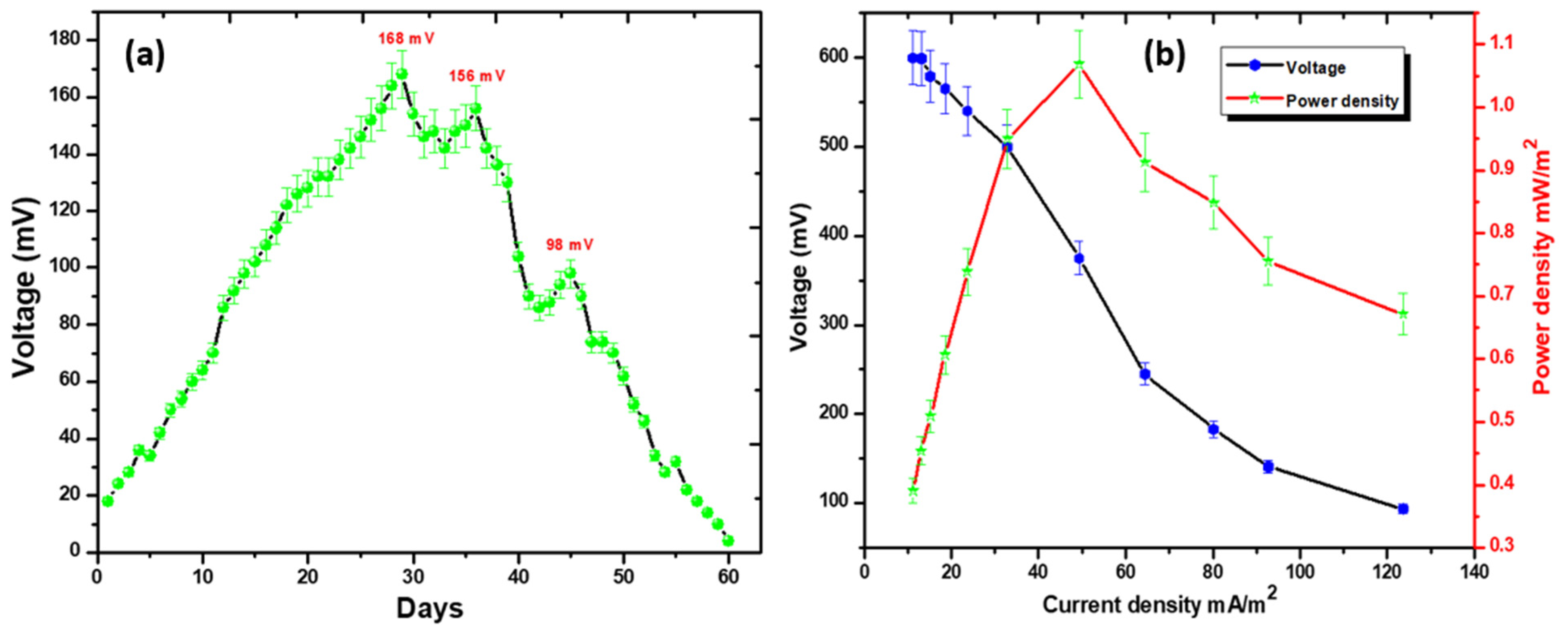
3.1. Voltage Trend, Internal Resistance, and Polarization Behavior

Rotten rice served as the organic substrate for the MFC experiments, and it was possible to operate the system for 60 days, which may be considered a relatively long period. According to Figure 2a, to generate the maximum voltage, the procedure was carried out for a total of three cycles. On day 29, the voltage reached its highest point of 168 mV, which corresponds to 0.168 mA. As soon as the first cycle was through, the voltage began to drop and this continued until it reached 142 mV. (0.142 mA). This shift may be due to the end of the life cycle of a particular type of bacteria in the consortium [18]. After a considerable amount of time, which could be considered as a lag phase for the microorganisms, voltage increased again and eventually reached a maximum of 156 mV; nevertheless, it was not as high as the maximum recorded in the first cycle. In a similar vein, voltage decreased even more in the third cycle and the value obtained was the lowest out of the three cycles. After 60 days of operation, the voltage eventually began a steady decline, which indicated that the process had been successfully completed. Under open circuit, a voltage of 650 mV was measured. In regard to MFC applications, the current findings are interesting when compared to the previous literature. For example, Yaqoob et al. [19] also stated that utilizing waste material as an organic substrate can deliver a maximum voltage as compared to commercial glucose or other sweeteners.
In addition, polarization tests were carried out to investigate the relationship between PD, CD, and voltage by adjusting the value of the external resistance. During the uninterrupted functioning of the MFC, the resistors with values ranging from 7000 Ω to 100 Ω were connected in series. The results showed that a high external resistance exhibited a poor electron transit owing to the electronic resistance and a significant degree of instability. On the other hand, the low external resistance demonstrated less stability in the electrical movement owing to the fast transfer of electrons. This was attributed to the fact that the transfer of electrons occurred more quickly [20]. To make possible electrical movement that is not hindered by ohmic resistance, it is necessary for the cell’s internal resistance as well as its exterior resistance to be similar. Prior to the procedure, a sequence of fixed external resistance was applied as a means of determining the correct value for the fixed external resistance [21,22]. The voltage dropped from the open-circuit voltage (OCV) when there was a lot of resistance from the outside, but eventually it gradually recovered. On the other hand, when the external resistance was varied, it was determined that 1000 Ω was the optimal cell design point. The PD and CD peaks that could be attained were 1.068 mW/m2 and 123.684 mA/m2, respectively.
The measured value for the component’s internal resistance was 733.0 Ω. Additionally, it is indicated that an increase in the external resistance of more than 1000 Ω may result in a reduction in the amount of electron transportation. Considering this, an external resistance of 1000 Ω has the potential to produce the maximum amount of energy generation in comparison to a higher resistance. During the investigation, it was found that 7000 Ω supplied a maximum of 0.39 mW/m2 PD, whereas 100 Ω delivered a maximum of 0.67 mW/m2 PD. This indicates that the electronic resistance is another component that must be taken into consideration to maintain a stable control of the electron resistivity. By shortening the distance between the anode and the cathode, it is possible to bring the value of the internal resistance down. This supports the fact that several pieces of research are conducted in one single-chamber MFC rather than a MFC with two chambers [23,24,25]. Additionally, Table S1 (Supplementary Materials) was also provided to compare the performance of the current MFC operation with earlier reports in the literature in terms of energy generation.

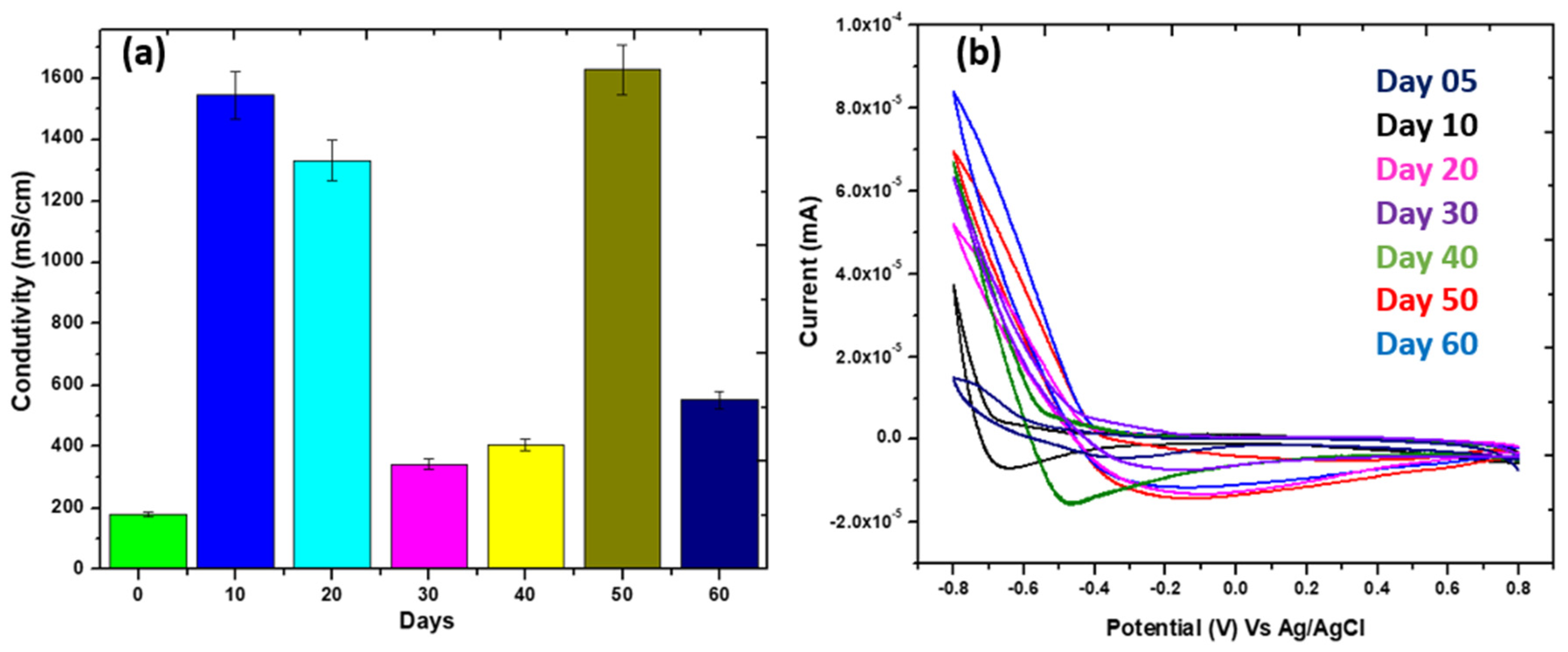
3.2. Conductivity Test and Cyclic Voltammetry Study

The conductivity trend of the cell is shown in Figure 3a. During the 60-day operation, conductivity data were measured at different intervals. From the 1st day (179 mS/cm) until the 50th day (1628 mS/cm), these values steadily increased. They gradually reduced after the 50th day until the last day of the operation (552 mS/cm). This also means that the conductivity was high on the 50th day, implying that there was a lot of voltage generation at that time. The system’s efficacy then deteriorates as a result of many factors including organic substrates, pH, bacterial instability, and temperature variations [26,27,28]. Recently, Rojas-Flores et al. [29] stated a similar conductivity effect in MFC operation.
As shown in Figure 3b, the observed CV curves at various time intervals were used to analyze the electrical mobility when operating MFCs. The CV curves depicted the forward scan (FS) and backward scan (RS) currents on various days in the forward and backward scans. When the FS (maximum oxidation current) was 1.7 × 10⁻⁵ mA, on day 5 and 8.2 × 10⁻⁵ mA on day 60, the RS (maximum reduction current) was (−1.5 × 10⁻⁵ mA) on day 5 and (−1.9 × 10⁻⁵ mA) on day 60. These FS values are indicating the oxidation of the compounds involved in the process which may be a mixture of several organic compounds in view of the organic substrate utilized and the various intermediates of the redox reactions that in turn undergo a redox cycle. Accordingly, the reduction (RS) is also pronounced due to the mixture of chemical species involved in the reactions that were occurring in the MFC, which also included the biodegradation of a complex molecule (hydroquinone). Day 60 presented the maximum FS and RS compared to the prior days. It signifies that the oxidation and reduction rates of the organic substrate were high and steadily increased. The oxidation rate peaked at 0.8 mA, whereas the reduction rate was −0.7 mA in this investigation. Throughout the experiment, the CV demonstrated the highest possible oxidation and reduction rates. As a result of the use of rotting rice as an organic substrate, the response was much more rapid than previously seen [19,30]. For calculating Cp values, the CV curves were also assessed. The Cp values indicated the biofilm’s growth rate and stability throughout the process. With rotten rice supplementation, we found that the biofilm was progressively formed and exhibited high stability. Low Cp values suggest that biofilm development is in progress or a slightly shifting but steadily increasing Cp value indicates good biofilm stability on the anode. Biofilm’s high Cp value was shown in Table 2 of this investigation. Hong et al. [31] also followed a similar procedure to highlight the biofilm formation rate and stability.

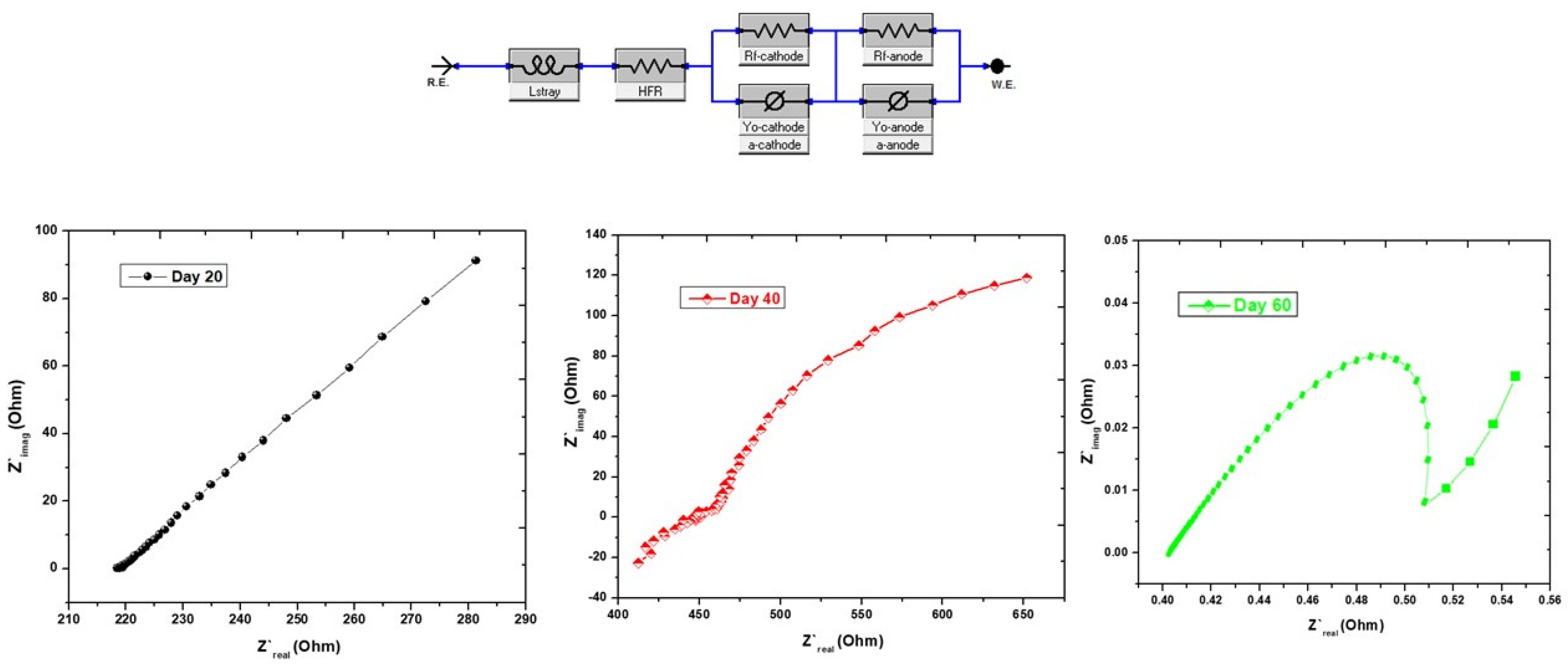
3.3. Electrochemical Impedance Spectroscopy Test

The Nyquist plot may take the form of a straight line or a semicircle. As was said before, the straight line represents the diffusion-regulated reaction, whereas the diameter of the semicircle indicates the resistance to charge transfer [32,33,34]. The ohmic resistance, denoted by Rs, and the charge transfer resistance, denoted by Rct, together referred to internal resistance. In addition, the activation of Rct and the Warburg resistance (W) in relation to a kinetic process are both covered by this electrochemical study [35]. The EIS technique was used to analyze Rct, Rs, W, and constant phase of fuel cell circuits, as shown in Figure 4. As indicated in EIS-day 20, the MFC’s total internal resistance was found to be 100.12 Ω (Rs = 61.25 Ω and Rct = 38.87 Ω). On the 40th day, total internal resistance was measured at 733 Ω (Rs = 723.9 Ω and Rct = 9.10 Ω), however on the 60th day, total internal resistance was recorded at 810.50 Ω (Rs = 790.85 Ω and Rct = 19.65 Ω). It is probable that the solution conductivity is also responsible for the significant internal resistance on day 60. The voltage trend also revealed that the voltage production was high for the first 40 days, but then steadily decreased. It means that when internal resistance increased, electron movement decreased. Internal resistance is influenced by several other factors as well, including electrolytes and the efficiency of organic substrates. Khan et al. [36] also used the EIS Nyquist plot to measure total internal resistance. Mei et al. [37] used the Nyquist plot to study Rct and Rs. Inoculum enhanced bioanode chamber’s ohmic resistance. As biofilm coverage on MFC electrodes grew, internal resistance may have risen on day 60. Analyte buildup increases basal medium intake, reducing internal resistance. The MFC’s Rs + Rct value on day 40 was 733 Ω, indicating that a biofilm was completely formed on the anode surface and improved electron transport near the anode electrolyte edge. This may help the biocatalytic activities on the anode and the transference of electrons to the cathode [38,39].

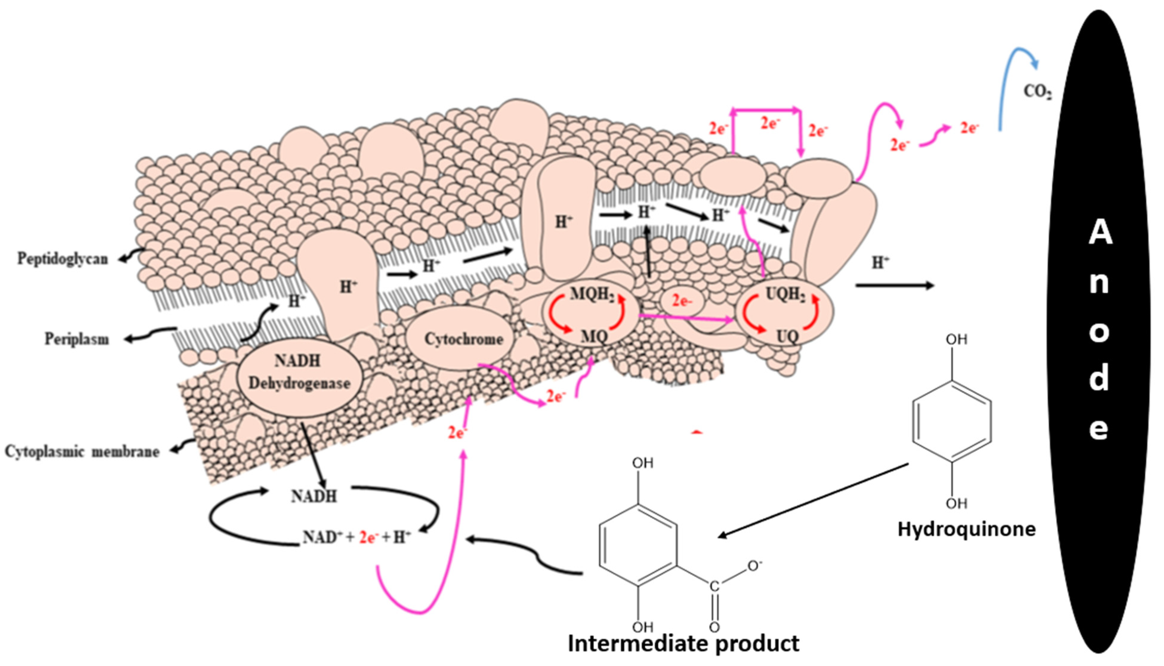
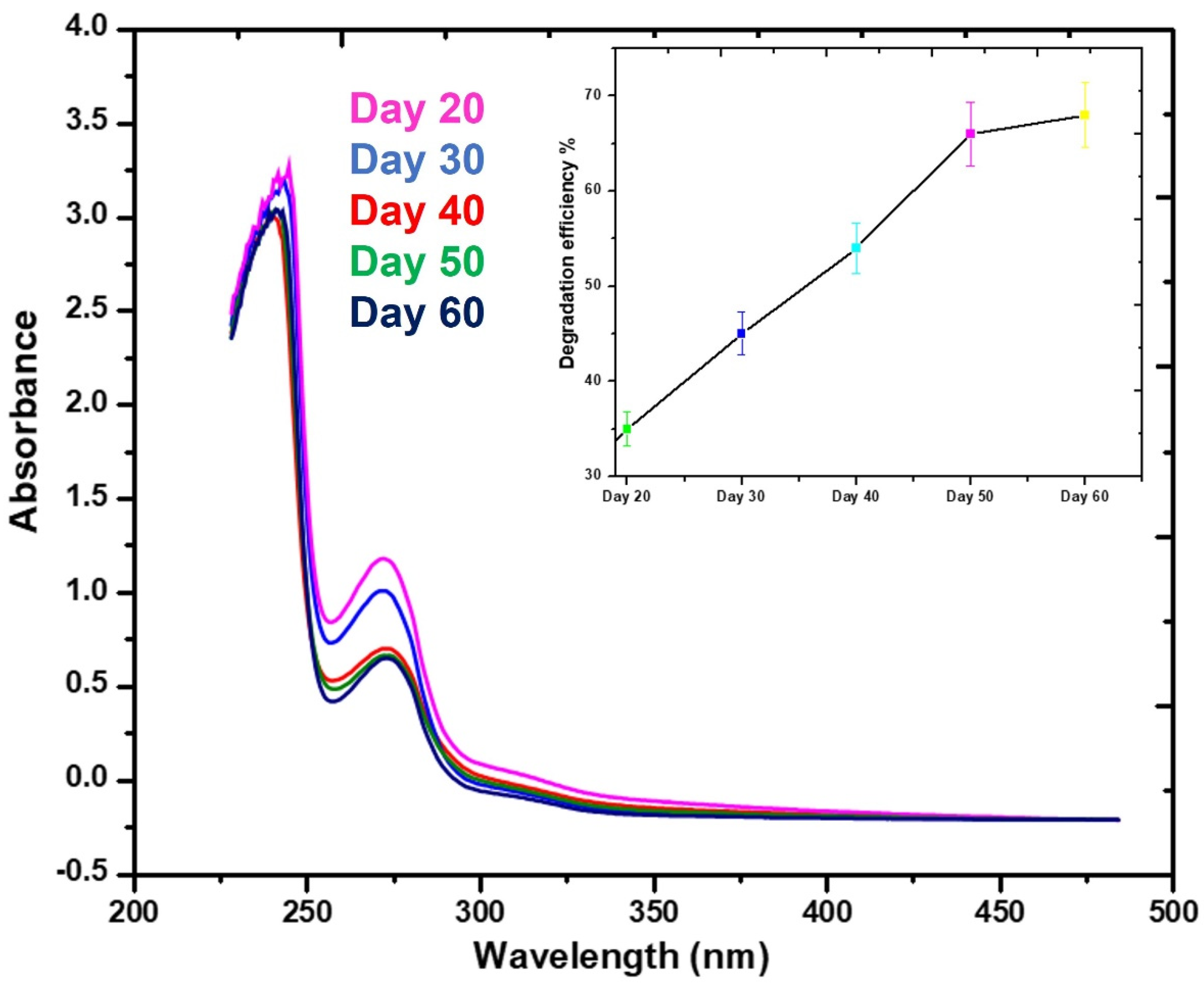
3.4. Hydroquinone Degradation Efficiency

The rotten rice was used as an organic substrate throughout the operation. The breakdown of hydroquinone was carried out by two different bacteria (exoelectrogens and biodegradative microbial species). The biodegradative microorganisms broke down hydroquinone and produced complete ring breakage, as shown in Figure 5, but the electroactive microbes are required for the degradation of the intermediates. The carboxylase hydroquinone mediates a full carboxylation process, which leads to the synthesis of 2,5-dihydroxybenzoic acid as an intermediate product [40]. Further cleavage of the intermediate, as shown in Figure 5, produces CO2 molecules and electrons through electroactive bacteria. The production of 2,5-dihydroxybenzoic acid from the oxidation of hydroquinone is shown in Figure 6. Due to the π → π * transition of aromatic molecule, the hydroquinone absorbance peak at λmax = 292 nm appears according to the previous literature [41]. After the process, the hydroquinone peaks were moved to λmax = 275 nm. Hydroquinone breakdown begins here, with the conversion of hydroquinone to 2,5-dihydroxybenzoic acid. The intermediate 2,5-dihydroxybenzoic acid presents more conjugation than hydroquinone because of electron delocalization. As a consequence of the carbonyl group transition, a peak of roughly 275 nm was observed. The previous literature has shown that 2,5-dihydroxybenzoic acid is produced between the UV range of 260–360 nm [26,42]. The graphs for the 50th and 60th days show almost full hydroquinone breakdown. The degradation efficiency of hydroquinone (68%) was determined using a calibration curve, as shown in Figure 6. The following equations explain the anode and cathode electrochemical processes that occur in the MFC based on these observations. No study on hydroquinone in a bioelectrochemical system was found after a thorough literature search.
Reaction at Anode:
Processes 10 02099 i001
Processes 10 02099 i002
Overall reaction at the anode:
Processes 10 02099 i003
Reaction at cathode:
Processes 10 02099 i004
Overall electrochemical reaction:
Processes 10 02099 i005

3.5. Oxidation of Rotten Rice in MFCs
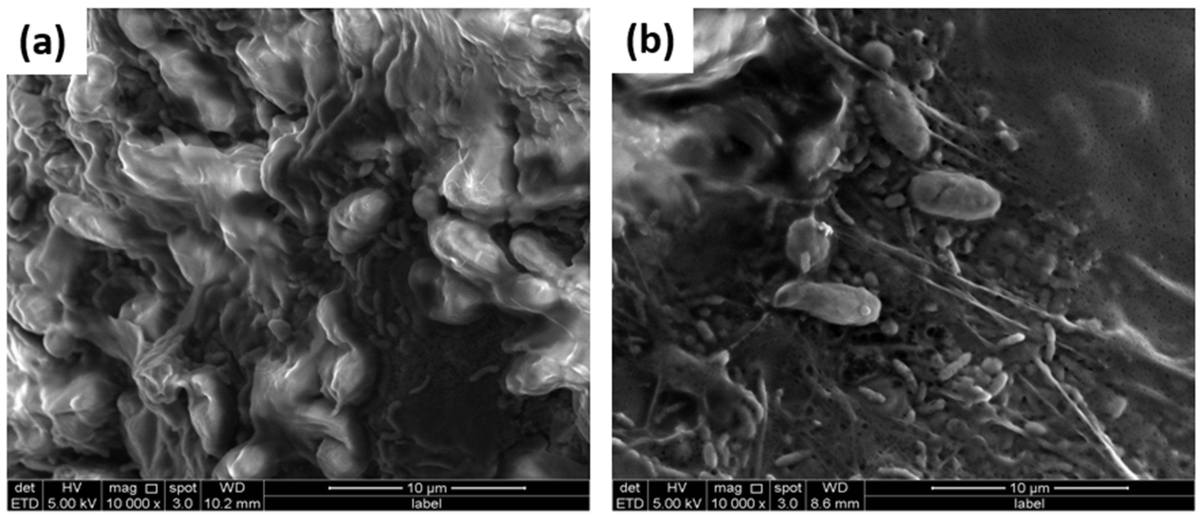
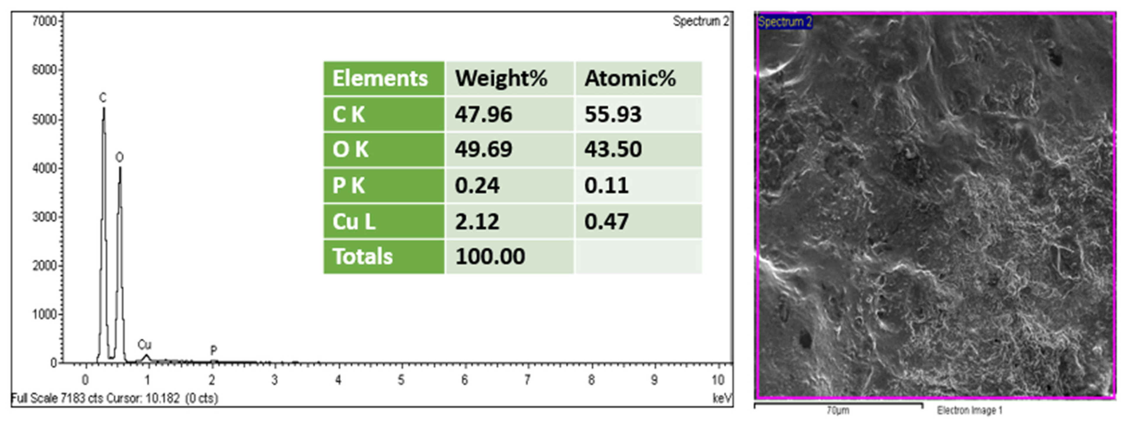
In order to produce, transport electrons and degrade pollutants, MFCs are dependent on the activity of microbes. Numerous microbial species, such as Enterobacter, Escherichia, Actinobacillus, Klebsiella and Bacillus, have been discovered as exoelectrogens (bacteria that generate energy) in the scientific literature [39,44,45,46]. In this experiment, rotten rice was used as an organic substrate for different types of microbes to grow on. In its original state, rotten rice was a disaccharide; however, it was later converted into glucose and subsequently oxidized by bacteria, which resulted in the production of electrons. The following is a concise summary of the oxidation and reduction reactions that were found in this study:
Oxidation reaction: Rotten rice → C6H12O6 + 6H2O → 6CO2 + 24H+ +24e
Reduction reaction: 24H+ + 24e + 6O2 → 12H2O
General reaction: C6H12O6 + 6O2 → 6CO2 + 6H2O + Electricity
During the process of oxidation, electrons that are produced at the anode electrode are transferred to the cathode electrode. Because the MFC used in this work was composed of just one chamber, this facilitated the transference of the protons from the anode chamber to the cathode chamber. The electrons are conducted via the outside circuit. In bacterial cells, electrons have to move via the anode electrode first before being able to be transported to the cathode electrode. The most representative mechanism for this transference is described in detail elsewhere [19,30].

3.6. Biofilm Study

A SEM-EDX study was performed to analyze the biological aspect of the process on the completion of the MFC operation. Figure 7 displays the SEM images of the treated anode and cathode. It can be observed in the SEM images that there is a dense population of different bacterial species, which may serve as evidence of the absence of toxicity during the process. Due to the abundant and distinct proliferation of bacterial species, it may be safe to state that the supply of organic substrate was enough for bacterial species to grow and function [46]. The organic substrate is a very essential factor in the growth and stability of bacteria populations during MFC operation. In the present investigation, unique findings were found. According to the findings of the SEM observation, it was noticed that there is essentially the same morphology visible, which consists of tube- or rod-like appendages on the filaments. In the field of MFCs, several studies have reported that the presence of filamentous appendages or rod-shaped morphology indicates the presence of conductive pili-based species. These conductive pili-based species include Acinetobacter, Lysinibacillus, Escherichia, and Klebsiella pneumoniae species according to the literature reports [19,47]. At the end, EDX analysis was performed to investigate the biofilms. On the surface of the biofilm, it was found that there was no harmful material. Figure 8 presents EDX spectra of the treated anode. This also suggests that the bacterial community growth was robust and sustained until the substrate was completely oxidized [48,49].

3.7. Bacterial Identification from Anode Electrode

The procedure of isolating and identifying bacteria was carried out with the intention of determining the bacterial species that are accountable for the removal of organic pollutant and the production of energy. The list of predominant bacterial species that were discovered on the surface of the anode throughout the course of this research is presented in Table 3. The Lacticaseibacillus, Pediococcus acidilactici and Secundilactobacillus silagincola species were the most prevalent in this investigation. All of them are believed to be exoelectrogens as well as metal-reducing species, based on the research that has been conducted in the past. Bacillus species were confirmed to be the source of the 0.000105 mW/m2 power density, as stated by Nimje et al. [50]. In addition to that, they referred to the Bacillus species as the well-known pollutant-reducing species. In a similar vein, Ayangbenro et al. [51] also investigated the Bacillus species as pollutant-reducing species with exoelectrogens properties. In addition to this, they concluded that the conductive pili of Bacillus species were responsible for the transportation of electrons from bacterial cells to the anode electrode. Several previous studies stated that the Lacticaseibacillus, Pediococcus acidilactici and Secundilactobacillus silagincola species were the most common exoelectrogens and degraders of the pollutants from wastewater [19,52,53].

4. Challenges and Future Recommendations

MFCs are now receiving a lot of attention, and this type of system has the potential to be employed in a wide number of applications, including wastewater bioremediation [54]. In spite of this, MFCs are still facing constraints due to the electrodes design and composition. The preparation of highly conductive electrodes and their modification can improve the rank of MFC technology within wastewater treatment and biodegradation of pollutants. The MFC is a ground-breaking technology that not only may provide humanity with energy that is clean, safe, and sustainable but also help to preserve the natural environment in which we live [55]. In addition, MFCs are a relatively new field of study in the scientific community; hence, it will need a significant amount of work and time before they can be considered economically viable. The instability of the organic substrate and electrode material is the emerging issue in MFCs [56]. In the present study, positive results were obtained, however, it was difficult to sustain the system for a longer period of time (over 60 days). The MFC commercial-scale operation requires an organic substrate that is stable over the long term. Recently, rotting rice was utilized as a substrate in MFCs, allowing the operation for 60 days. Requirements for a long term functional organic substrate include high-stability and a high amount of carbohydrates to consider the scaling up of MFCs to pilot-plant dimensions. The electrode material is another important issue that must be considered in MFC design. Due to the material of the electrodes, the MFC was unable to produce an adequate amount of energy. Electrode material, in particular anode material, should be able to transfer electrons more efficiently and offer a biocompatible environment for bacteria to develop a biofilm around the anode surface [57,58]. In recent years, the electrode material that is fabricated from biomass has gained much attention owing to the low cost and performance it offers. The transformation of biomass into electrodes, such as biomass-derived anode electrodes, has been the subject of much research in the past [59]. At this time, this area of work is of uppermost importance.

5. Conclusions

The performance of a MFC supplemented with rotten rice as a substrate to produce energy coupled to hydroquinone biodegradation was emphasized in this research. The overall results obtained from the system supported with waste-derived substrate were remarkable compared to results presented on the topic in previous reports. The generation of a voltage of 168 mV was accomplished in a span of 29 days. The degradation efficiency of hydroquinone was 68%. In the present work, the biological characterizations proved that there was a stable and matured biofilm. The bacterial species that have been identified are also an encouraging indicator for an efficient biodegradation and the generation of energy through the oxidation of rotten rice and hydroquinone. To the best of our knowledge, the use of hydroquinone as an electron donor in bioelectrochemical fuel cells has not been the subject of previous research. This research may give rise to a novel concept for the improvement of simultaneous energy production and the biodegradation of organic pollutants.

Supplementary Materials

The following supporting information can be downloaded at: https://www.mdpi.com/article/10.3390/pr10102099/s1, Table S1: Comparative profile of different organic substrates used in MFC.

Author Contributions

M.N.M.I., A.A. and F.H.: Conceptualization. T.A.M.T.: methodology, writing-original draft preparation. S.-E.O. and F.H.: visualization. M.B.A., C.G.-B.: result interpretations, English editing of manuscript. A.A., M.N.M.I.: supervision, funding acquisition. This article has been read and approved by all listed authors. All authors have read and agreed to the published version of the manuscript.

Funding

This research received no external funding.

Institutional Review Board Statement

Not applicable.

Informed Consent Statement

Not applicable.

Data Availability Statement

The authors confirm that all data underlying the findings are fully available without restriction. Data can be obtained after submitting a request to the corresponding/first author.

Acknowledgments

The authors extend their appreciation to the Chemistry Department, College of Sciences and Humanities, Prince Sattam bin Abdulaziz University, Al-Kharj 11942, Saudi Arabia.

Conflicts of Interest

The authors declare no competing interests.

References

  1. Santoro, C.; Arbizzani, C.; Erable, B.; Ieropoulos, I. Microbial fuel cells: From fundamentals to applications. A review. J. Power Sources 2017, 356, 225–244. [Google Scholar] [CrossRef] [PubMed]
  2. Logan, B.E.; Regan, J.M. Microbial fuel cells—Challenges and applications. Environ. Sci. Technol. 2006, 40, 5172–5180. [Google Scholar] [CrossRef] [Green Version]
  3. Logan, B.E.; Hamelers, B.; Rozendal, R.; Schröder, U.; Keller, J.; Freguia, S.; Aelterman, P.; Verstraete, W.; Rabaey, K. Microbial fuel cells: Methodology and technology. Environ. Sci. Technol. 2006, 40, 5181–5192. [Google Scholar] [CrossRef]
  4. Hussain, F.; Al-Zaqri, N.; Adnan, A.B.M.; Hussin, M.H.; Oh, S.E.; Umar, K. Impact of bakery waste as an organic substrate on microbial fuel cell performance. Sustain. Energy Technol. Assess. 2022, 53, 1–9. [Google Scholar] [CrossRef]
  5. Sharma, A.; Sharma, R.K.; Kim, Y.-K.; Lee, H.-J.; Tripathi, K.M. Upgrading of seafood waste as a carbon source: Nano-world outlook. J. Environ. Chem. Eng. 2021, 9, 106656. [Google Scholar] [CrossRef]
  6. Yaqoob, A.A.; Khatoon, A.; Mohd Setapar, S.H.; Umar, K.; Parveen, T.; Mohamad Ibrahim, M.N.; Ahmad, A.; Rafatullah, M. Outlook on the role of microbial fuel cells in remediation of environmental pollutants with electricity generation. Catalysts 2020, 10, 819. [Google Scholar] [CrossRef]
  7. Huang, L.; Regan, J.M.; Quan, X. Electron transfer mechanisms, new applications, and performance of biocathode microbial fuel cells. Bioresour. Technol. 2011, 102, 316–323. [Google Scholar] [CrossRef]
  8. Daud, N.N.M.; Ahmad, A.; Ibrahim, M.N.M. Application of rotten rice as a substrate for bacterial species to generate energy and the removal of toxic metals from wastewater through microbial fuel cells. Environ. Sci. Pollut. Res. 2021, 28, 62816–62827. [Google Scholar] [CrossRef]
  9. Rissato, S.R.; Galhiane, M.S.; de Almeida, M.V.; Gerenutti, M.; Apon, B.M. Multiresidue determination of pesticides in honey samples by gas chromatography–mass spectrometry and application in environmental contamination. Food Chem. 2007, 101, 1719–1726. [Google Scholar] [CrossRef]
  10. Kumar, S.S.; Kumar, V.; Malyan, S.K.; Sharma, J.; Mathimani, T.; Maskarenj, M.S.; Ghosh, P.C.; Pugazhendhi, A. Microbial fuel cells (MFCs) for bioelectrochemical treatment of different wastewater streams. Fuel 2019, 254, 115526. [Google Scholar] [CrossRef]
  11. Das, D. A bioelectrochemical system that converts waste to watts. In Microbial Fuel Cell; Springer: Cham, Switzerland, 2017. [Google Scholar]
  12. Idris, M.O.; Kim, H.C. Exploring the effectiveness of microbial fuel cell for the degradation of organic pollutants coupled with bio-energy generation. Sustain. Energy Technol. Assess. 2022, 52, 102183. [Google Scholar] [CrossRef]
  13. Nordlund, J.; Grimes, P.; Ortonne, J.P. The safety of hydroquinone. J. Eur. Acad. Dermatol. Venereol. 2006, 20, 781–787. [Google Scholar] [CrossRef]
  14. Enguita, F.J.; Leitão, A.L. Hydroquinone: Environmental pollution, toxicity, and microbial answers. BioMed Res. Int. 2013, 2013, 542168. [Google Scholar] [CrossRef] [Green Version]
  15. Suresh, S.; Srivastava, V.C.; Mishra, I.M. Adsorption of catechol, resorcinol, hydroquinone, and their derivatives: A review. Int. J. Energy Environ. Eng. 2012, 3, 32. [Google Scholar] [CrossRef]
  16. McGregor, D. Hydroquinone: An evaluation of the human risks from its carcinogenic and mutagenic properties. Crit. Rev. Toxicol. 2007, 37, 887–914. [Google Scholar] [CrossRef]
  17. Serrà, A.; Yaakop, A.S. Self-assembled oil palm biomass-derived modified graphene oxide anode: An efficient medium for energy transportation and bioremediating Cd (II) via microbial fuel cells. Arab. J. Chem. 2021, 14, 103121. [Google Scholar]
  18. Greenman, J.; Gajda, I.; You, J.; Mendis, B.A.; Obata, O.; Pasternak, G.; Ieropoulos, I. Microbial fuel cells and their electrified biofilms. Biofilm 2021, 3, 100057. [Google Scholar] [CrossRef]
  19. Yaqoob, A.A.; Ibrahim, M.N.M.; Yaakop, A.S.; Umar, K.; Ahmad, A. Modified Graphene Oxide Anode: A Bioinspired Waste Material for Bioremediation of Pb2+ with Energy Generation through Microbial Fuel Cells. Chem. Eng. J. 2020, 417, 128052. [Google Scholar] [CrossRef]
  20. Rinaldi, A.; Mecheri, B.; Garavaglia, V.; Licoccia, S.; Di Nardo, P.; Traversa, E. Engineering materials and biology to boost performance of microbial fuel cells: A critical review. Energy Environ. Sci. 2008, 1, 417–429. [Google Scholar] [CrossRef]
  21. Zhang, F.; He, Z. Simultaneous nitrification and denitrification with electricity generation in dual-cathode microbial fuel cells. J. Chem. Technol. Biotechnol. 2012, 87, 153–159. [Google Scholar] [CrossRef]
  22. Ren, H.; Lee, H.-S.; Chae, J. Miniaturizing microbial fuel cells for potential portable power sources: Promises and challenges. Microfluid. Nanofluidics 2012, 13, 353–381. [Google Scholar] [CrossRef]
  23. Du, Z.; Li, H.; Gu, T. A state of the art review on microbial fuel cells: A promising technology for wastewater treatment and bioenergy. Biotechnol. Adv. 2007, 25, 464–482. [Google Scholar] [CrossRef] [PubMed]
  24. Do, M.; Ngo, H.; Guo, W.; Liu, Y.; Chang, S.; Nguyen, D.; Nghiem, L.; Ni, B. Challenges in the application of microbial fuel cells to wastewater treatment and energy production: A mini review. Sci. Total Environ. 2018, 639, 910–920. [Google Scholar] [CrossRef] [PubMed]
  25. Chae, K.-J.; Choi, M.-J.; Kim, K.-Y.; Ajayi, F.; Park, W.; Kim, C.-W.; Kim, I.S. Methanogenesis control by employing various environmental stress conditions in two-chambered microbial fuel cells. Bioresour. Technol. 2010, 101, 5350–5357. [Google Scholar] [CrossRef] [PubMed]
  26. Berkenkamp, S.; Menzel, C.; Karas, M.; Hillenkamp, F. Performance of infrared matrix-assisted laser desorption/ionization mass spectrometry with lasers emitting in the 3 μm wavelength range. Rapid Commun. Mass Spectrom. 1997, 11, 1399–1406. [Google Scholar] [CrossRef]
  27. Yaqoob, A.A.; Ibrahim, M.N.M.; Umar, K. Biomass-derived composite anode electrode: Synthesis, characterizations, and application in microbial fuel cells (MFCs). J. Environ. Chem. Eng. 2021, 9, 106111. [Google Scholar] [CrossRef]
  28. Yaqoob, A.A.; Ibrahim, M.N.M.; Rodríguez-Couto, S.; Ahmad, A. Preparation, characterization, and application of modified carbonized lignin as an anode for sustainable microbial fuel cell. Process Saf. Environ. Prot. 2021, 155, 49–60. [Google Scholar] [CrossRef]
  29. Rojas-Flores, S.; Benites, S.M.; La Cruz-Noriega, D.; Cabanillas-Chirinos, L.; Valdiviezo-Dominguez, F.; Quezada Álvarez, M.A.; Vega-Ybañez, V.; Angelats-Silva, L. Bioelectricity Production from Blueberry Waste. Processes 2021, 9, 1301. [Google Scholar] [CrossRef]
  30. Yaqoob, A.A.; Mohamad Ibrahim, M.N.; Umar, K.; Bhawani, S.A.; Khan, A.; Asiri, A.M.; Khan, M.R.; Azam, M.; AlAmmari, A.M. Cellulose Derived Graphene/Polyaniline Nanocomposite Anode for Energy Generation and Bioremediation of Toxic Metals via Benthic Microbial Fuel Cells. Polymers 2021, 13, 135. [Google Scholar] [CrossRef] [PubMed]
  31. Hong, Y.; Call, D.F.; Werner, C.M.; Logan, B.E. Adaptation to high current using low external resistances eliminates power overshoot in microbial fuel cells. Biosens. Bioelectron. 2011, 28, 71–76. [Google Scholar] [CrossRef]
  32. Anwer, A.; Khan, M.; Khan, N.; Nizami, A.; Rehan, M.; Khan, M. Development of novel MnO2 coated carbon felt cathode for microbial electroreduction of CO2 to biofuels. J. Environ. Manag. 2019, 249, 109376. [Google Scholar] [CrossRef] [PubMed]
  33. Nasar, A.; Rahman, M.M. Applications of chitosan (CHI)-reduced graphene oxide (rGO)-polyaniline (PAni) conducting composite electrode for energy generation in glucose biofuel cell. Sci. Rep. 2020, 10, 10428. [Google Scholar]
  34. Kim, B.; Chang, I.S.; Dinsdale, R.M.; Guwy, A.J. Accurate measurement of internal resistance in microbial fuel cells by improved scanning electrochemical impedance spectroscopy. Electrochim. Acta 2021, 366, 137388. [Google Scholar] [CrossRef]
  35. Yousefi, V.; Mohebbi-Kalhori, D.; Samimi, A. Equivalent electrical circuit modeling of ceramic-based microbial fuel cells using the electrochemical impedance spectroscopy (EIS) analysis. J. Renew. Energy Environ. 2019, 6, 21–28. [Google Scholar]
  36. Khan, M.D.; Li, D.; Tabraiz, S.; Shamurad, B.; Scott, K.; Khan, M.Z.; Yu, E.H. Integrated air cathode microbial fuel cell-aerobic bioreactor set-up for enhanced bioelectrodegradation of azo dye Acid Blue 29. Sci. Total Environ. 2021, 756, 143752. [Google Scholar] [CrossRef]
  37. Mei, B.-A.; Munteshari, O.; Lau, J.; Dunn, B.; Pilon, L. Physical interpretations of Nyquist plots for EDLC electrodes and devices. J. Phys. Chem. C 2018, 122, 194–206. [Google Scholar] [CrossRef]
  38. Paitier, A.; Godain, A.; Lyon, D.; Haddour, N.; Vogel, T.M.; Monier, J.-M. Microbial fuel cell anodic microbial population dynamics during MFC start-up. Biosens. Bioelectron. 2017, 92, 357–363. [Google Scholar] [CrossRef]
  39. Li, M.; Zhou, M.; Tian, X.; Tan, C.; McDaniel, C.T.; Hassett, D.J.; Gu, T. Microbial fuel cell (MFC) power performance improvement through enhanced microbial electrogenicity. Biotechnol. Adv. 2018, 36, 1316–1327. [Google Scholar] [CrossRef]
  40. Dai, P.-X.; Chen, T.; Wang, D.; Wan, L.-J. Potential dependent adsorption geometry of 2, 5-dihydroxybenzoic acid on a Au (111) surface: An in situ electrochemical scanning tunneling microscopy study. J. Phys. Chem. C 2012, 116, 6208–6214. [Google Scholar] [CrossRef]
  41. Chibac, A.L.; Buruiana, T.; Melinte, V.; Buruiana, E.C. Photocatalysis applications of some hybrid polymeric composites incorporating TiO2 nanoparticles and their combinations with SiO2/Fe2O3. Beilstein J. Nanotechnol. 2017, 8, 272–286. [Google Scholar] [CrossRef] [PubMed] [Green Version]
  42. Bourcier, S.; Bouchonnet, S.; Hoppilliard, Y. Ionization of 2, 5-dihydroxybenzoic acid (DHB) matrix-assisted laser desorption ionization experiments and theoretical study. Int. J. Mass Spectrom. 2001, 210, 59–69. [Google Scholar] [CrossRef]
  43. Umar, M.F.; Rafatullah, M.; Ibrahim, M.N.M.; Ismail, N. Bioelectricity production and xylene biodegradation through double chamber benthic microbial fuel cells fed with sugarcane waste as a substrate. J. Hazard. Mater. 2021, 419, 126469. [Google Scholar] [CrossRef]
  44. Solanki, K.; Subramanian, S.; Basu, S. Microbial fuel cells for azo dye treatment with electricity generation: A review. Bioresour. Technol. 2013, 131, 564–571. [Google Scholar] [CrossRef]
  45. Sharma, V.; Kundu, P. Biocatalysts in microbial fuel cells. Enzym. Microb. Technol. 2010, 47, 179–188. [Google Scholar] [CrossRef]
  46. Fadzli, F.S.; Rashid, M. Electricity generation and heavy metal remediation by utilizing yam (Dioscorea alata) waste in benthic microbial fuel cells (BMFCs). Biochem. Eng. J. 2021, 172, 108067. [Google Scholar] [CrossRef]
  47. Yaqoob, A.A.; Idris, M.O.; Ahmad, A.; Daud, N.N.M.; Ibrahim, M.N.M. Removal of Toxic Metal Ions from Wastewater Through Microbial Fuel Cells. In Microbial Fuel Cells for Environmental Remediation; Springer: Singapore, 2022; pp. 299–325. [Google Scholar]
  48. Yaakop, A.S. Application of oil palm lignocellulosic derived material as an efficient anode to boost the toxic metal remediation trend and energy generation through microbial fuel cells. J. Clean. Prod. 2021, 314, 128062. [Google Scholar]
  49. Guerrero–Barajas, C.; Umar, K.; Yaakop, A.S. Local fruit wastes driven benthic microbial fuel cell: A sustainable approach to toxic metal removal and bioelectricity generation. Environ. Sci. Pollut. Res. 2022, 29, 32913–32928. [Google Scholar]
  50. Nimje, V.R.; Chen, C.-Y.; Chen, C.-C.; Jean, J.-S.; Reddy, A.S.; Fan, C.-W.; Pan, K.-Y.; Liu, H.-T.; Chen, J.-L. Stable and high energy generation by a strain of Bacillus subtilis in a microbial fuel cell. J. Power Sources 2009, 190, 258–263. [Google Scholar] [CrossRef]
  51. Ayangbenro, A.S.; Babalola, O.O. Genomic analysis of Bacillus cereus NWUAB01 and its heavy metal removal from polluted soil. Sci. Rep. 2020, 10, 19660. [Google Scholar] [CrossRef]
  52. Yaqoob, A.A.; Al-Zaqri, N.; Yaakop, A.S.; Umar, K. Potato waste as an effective source of electron generation and bioremediation of pollutant through benthic microbial fuel cell. Sustain. Energy Technol. Assess. 2022, 53, 102560. [Google Scholar] [CrossRef]
  53. Bakar, M.A.B.A.; Kim, H.-C.; Ahmad, A.; Alshammari, M.B.; Yaakop, A.S. Oxidation of food waste as an organic substrate in a single chamber microbial fuel cell to remove the pollutant with energy generation. Sustain. Energy Technol. Assess. 2022, 52, 102282. [Google Scholar]
  54. Fadzli, F.; Yaakop, A. Benthic microbial fuel cells: A sustainable approach for metal remediation and electricity generation from sapodilla waste. Int. J. Environ. Sci. Technol. 2022, 1–14. [Google Scholar] [CrossRef]
  55. Yaqoob, S.B.; Bhawani, S.A.; Ismail Abdulrahman, R.M. Utilization of Mangifera indica as Substrate to Bioremediate the Toxic Metals and Generate the Bioenergy through a Single-Chamber Microbial Fuel Cell. J. Chem. 2021, 2021, 8552701. [Google Scholar] [CrossRef]
  56. Fadzli, F.S.; Bhawani, S.A.; Adam Mohammad, R.E. Microbial fuel cell: Recent developments in organic substrate use and bacterial electrode interaction. J. Chem. 2021, 2021, 4570388. [Google Scholar] [CrossRef]
  57. Yaqoob, A.A.; Ibrahim, M.N.M.; Guerrero-Barajas, C. Modern trend of anodes in microbial fuel cells (MFCs): An overview. Environ. Technol. Innov. 2021, 23, 101579. [Google Scholar] [CrossRef]
  58. Serrà, A.; Bhawani, S.A.; Ibrahim, M.N.M.; Khan, A.; Alorfi, H.S.; Asiri, A.M.; Hussein, M.A.; Khan, I.; Umar, K. Utilizing Biomass-Based Graphene Oxide–Polyaniline–Ag Electrodes in Microbial Fuel Cells to Boost Energy Generation and Heavy Metal Removal. Polymers 2022, 14, 845. [Google Scholar]
  59. Yaqoob, A.A.; Ibrahim, M.N.M.; Yaakop, A.S.; Rafatullah, M. Utilization of biomass-derived electrodes: A journey toward the high performance of microbial fuel cells. Appl. Water Sci. 2022, 12, 99. [Google Scholar] [CrossRef]
Figure 1. MFC set-up for hydroquinone degradation.
Processes 10 02099 g001
Figure 2. (a) Voltage generation trend and (b) polarization curve of the present work.
Processes 10 02099 g002
Figure 3. (a) Values of conductivity at various time intervals and (b) CV curves.
Processes 10 02099 g003
Figure 4. An EIS analysis of the MFC operation on the 20th, 40th and 60th days.
Processes 10 02099 g004
Figure 5. Microbial degradation of hydroquinone in a single-chamber MFC (Idea and figure modified according to the present study from reference [43] with Elsevier permission).
Processes 10 02099 g005
Figure 6. UV–visible curves of treated hydroquinone from MFC operation.
Processes 10 02099 g006
Figure 7. SEM images of (a) treated anode and (b) treated cathode on day 60.
Processes 10 02099 g007
Figure 8. EDX spectra of anodic biofilm.
Processes 10 02099 g008
Table 1. The lake and synthetic wastewater parameters used.
ParametersLake WastewaterSynthetic Wastewater
Color GreenishCloudy
Electrical conductivity5.60 µs/cm11.05 µs/cm
Temperature 25 ± 2 °C25 ± 2 °C
pH6.907.19
Odor Unpleasant smellUnpleasant smell
Hydroquinone Concentration 0 ppm10 ppm
Table 2. CV curves may be used to monitor biofilm growth by computing the Cp values at various intervals of operation.
Measurement Time IntervalCapacitance (F/g)
5th7.20 × 10−5
10th2.70 × 10−4
20th2.76 × 10−4
30th2.82 × 10−4
40th2.88 × 10−4
50th3.00 × 10−4
60th5.04 × 10−4
Table 3. List of identified bacterial species from anode electrode.
Bacterial Species Identity (%) Query Cover (%)Accession Number (16S rRNA Gene)
Lacticaseibacillus paracasei98.0399NR_025880.1
Lacticaseibacillus paracasei98.0099NR_113337.1
Pediococcus acidilactici93.0899NR_042057.1
Latilactobacillus species93.0099NR_042443.1
Loigolactobacillus backii93.4998NR_114385.1
Pediococcus stilesii93.5998NR_042401.1
Secundilactobacillus silagincola92.9098NR_158059.1
Publisher’s Note: MDPI stays neutral with regard to jurisdictional claims in published maps and institutional affiliations.

