

Digital Workflow for Producing Hybrid Posts and Cores
 ,
, 
Abstract
:1. Introduction
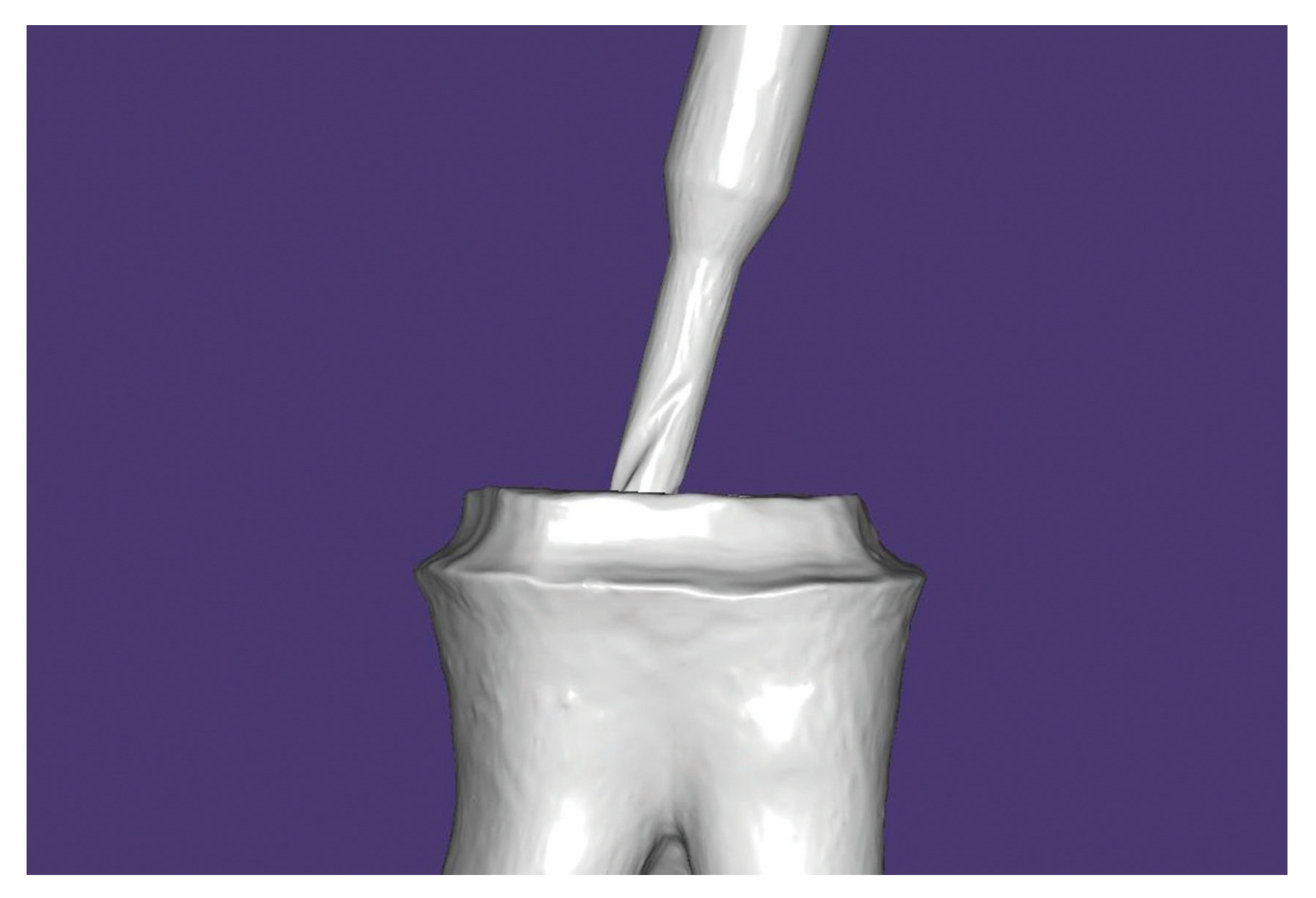
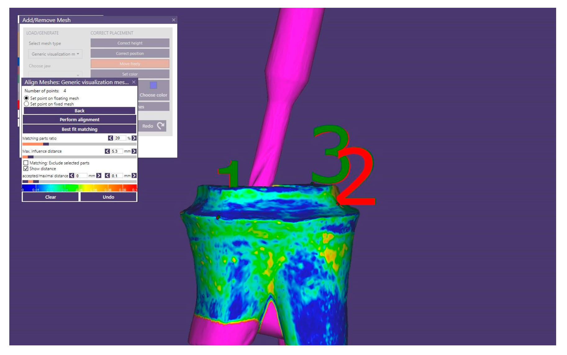
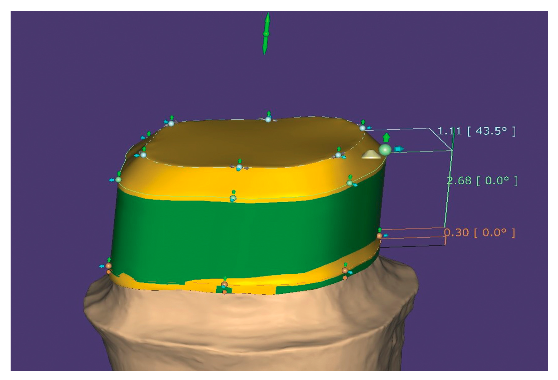
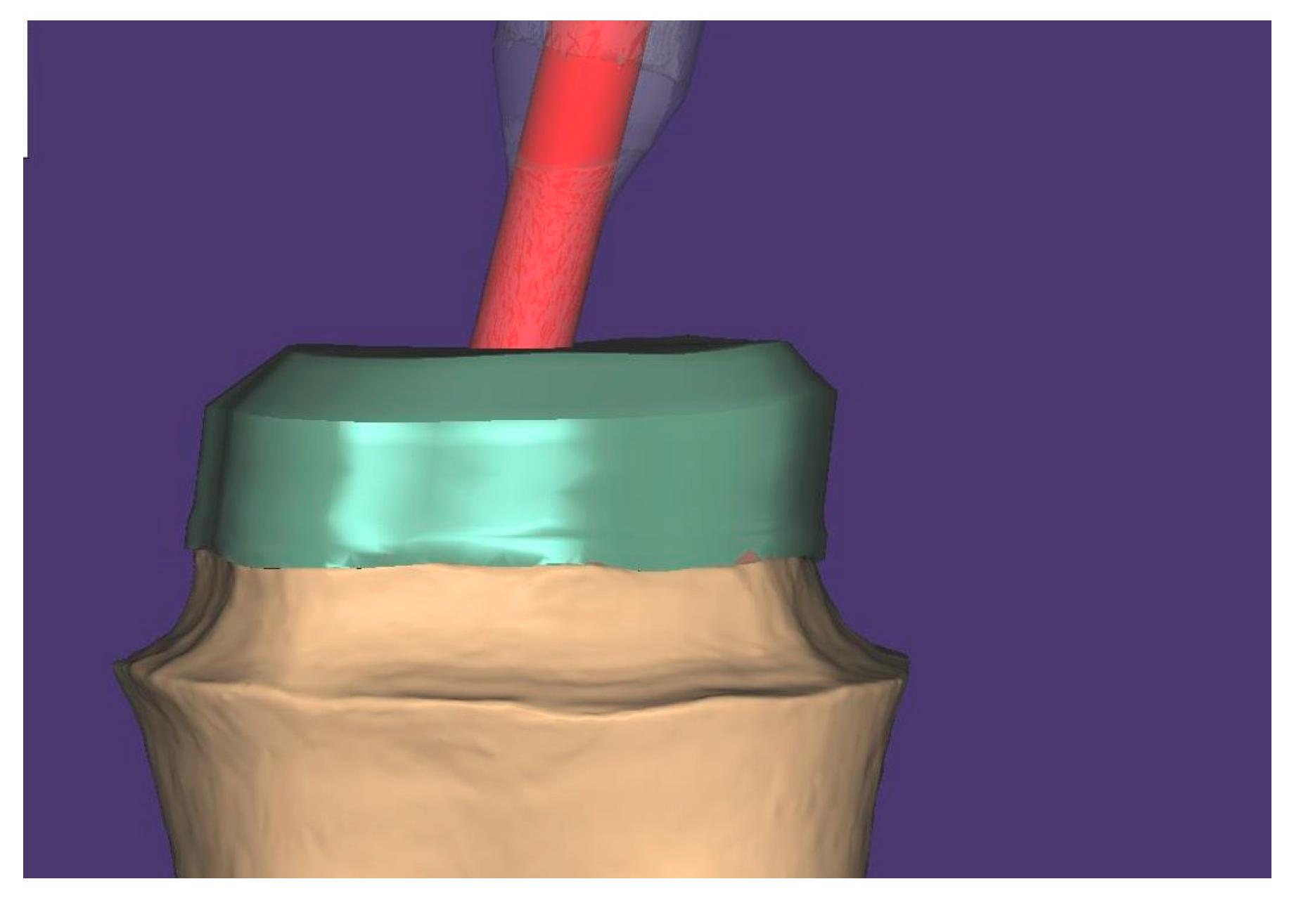
2. Technique
3. Discussion
4. Conclusions
Author Contributions
Funding
Institutional Review Board Statement
Informed Consent Statement
Data Availability Statement
Conflicts of Interest
References
- Zicari, F.; Couthino, E.; De Munck, J.; Poitevin, A.; Scotti, R.; Naert, I.; Van Meerbeek, B. Bonding Effectiveness and Sealing Ability of Fiber-Post Bonding. Dent. Mater. 2008, 24, 967–977. [Google Scholar] [CrossRef] [PubMed]
- Libonati, A.; Marzo, G.; Klinger, F.G.; Farini, D.; Gallusi, G.; Tecco, S.; Mummolo, S.; De Felici, M.; Campanella, V. Embryotoxicity Assays for Leached Components from Dental Restorative Materials. Reprod. Biol. Endocrinol. RBE 2011, 9, 136. [Google Scholar] [CrossRef] [PubMed] [Green Version]
- Liu, P.; Deng, X.-L.; Wang, X.-Z. Use of a CAD/CAM-Fabricated Glass Fiber Post and Core to Restore Fractured Anterior Teeth: A Clinical Report. J. Prosthet. Dent. 2010, 103, 330–333. [Google Scholar] [CrossRef] [PubMed]
- Lee, J.-H.; Sohn, D.-S.; Lee, C.-H. Fabricating a Fiber-Reinforced Post and Zirconia Core with CAD/CAM Technology. J. Prosthet. Dent. 2014, 112, 683–685. [Google Scholar] [CrossRef] [PubMed]
- Falcão Spina, D.R.; da Costa, R.G.; Correr, G.M.; Rached, R.N. Scanning of Root Canal Impression for the Fabrication of a Resin CAD-CAM-Customized Post-and-Core. J. Prosthet. Dent. 2018, 120, 242–245. [Google Scholar] [CrossRef] [PubMed]
- Bru, E.; Forner, L.; Llena, C.; Almenar, A. Fibre Post Behaviour Prediction Factors. A Review of the Literature. J. Clin. Exp. Dent. 2013, 5, e150–e153. [Google Scholar] [CrossRef] [PubMed] [Green Version]
- Lassila, L.V.J.; Tanner, J.; Le Bell, A.-M.; Narva, K.; Vallittu, P.K. Flexural Properties of Fiber Reinforced Root Canal Posts. Dent. Mater. 2004, 20, 29–36. [Google Scholar] [CrossRef] [PubMed]
- Goracci, C.; Ferrari, M. Current Perspectives on Post Systems: A Literature Review. Aust. Dent. J. 2011, 56 (Suppl. S1), 77–83. [Google Scholar] [CrossRef] [PubMed]
- Scotti, N.; Bergantin, E.; Tempesta, R.; Turco, G.; Breschi, L.; Farina, E.; Pasqualini, D.; Berutti, E. Influence of Dentin Pretreatment with Synthetic Hydroxyapatite Application on the Bond Strength of Fiber Posts Luted with 10-Methacryloyloxydecyl Dihydrogen Phosphate-Containing Luting Systems. Eur. J. Oral Sci. 2016, 124, 504–509. [Google Scholar] [CrossRef] [PubMed]
- Lee, J.-H. Accelerated Techniques for a Post and Core and a Crown Restoration with Intraoral Digital Scanners and CAD/CAM and Rapid Prototyping. J. Prosthet. Dent. 2014, 112, 1024–1029. [Google Scholar] [CrossRef] [PubMed]
- Nagaoka, N.; Yoshihara, K.; Feitosa, V.P.; Tamada, Y.; Irie, M.; Yoshida, Y.; Van Meerbeek, B.; Hayakawa, S. Chemical Interaction Mechanism of 10-MDP with Zirconia. Sci. Rep. 2017, 7, 45563. [Google Scholar] [CrossRef] [PubMed] [Green Version]
- Li, R.; Zhou, H.; Wei, W.; Wang, C.; Sun, Y.C.; Gao, P. Effects of Mechanical and Chemical Pretreatments of Zirconia or Fiber Posts on Resin Cement Bonding. PLoS ONE 2015, 10, e0129690. [Google Scholar] [CrossRef] [PubMed] [Green Version]
- Rosenstiel, S.F.; Land, M.F.; Fujimoto, J. Contemporary Fixed Prosthodontics; Elsevier Health Sciences: Melbourne, Australia, 2006; ISBN 978-0-323-02874-5. [Google Scholar]
- Rayyan, M.R.; Aldossari, R.A.; Alsadun, S.F.; Hijazy, F.R. Accuracy of Cast Posts Fabricated by the Direct and the Indirect Techniques. J. Prosthet. Dent. 2016, 116, 411–415. [Google Scholar] [CrossRef] [PubMed]
- Pinto, A.; Arcuri, L.; Carosi, P.; Nardi, R.; Libonati, A.; Ottria, L.; Campanella, V. In Vitro Evaluation of the Post-Space Depth Reading with an Intraoral Scanner (IOS) Compared to a Traditional Silicon Impression. Oral Implantol. 2017, 10, 360–368. [Google Scholar] [CrossRef] [PubMed]
- Jeon, J.-H.; Kim, H.-Y.; Kim, J.-H.; Kim, W.-C. Accuracy of 3D White Light Scanning of Abutment Teeth Impressions: Evaluation of Trueness and Precision. J. Adv. Prosthodont. 2014, 6, 468–473. [Google Scholar] [CrossRef] [PubMed] [Green Version]
- Kurz, M.; Attin, T.; Mehl, A. Influence of Material Surface on the Scanning Error of a Powder-Free 3D Measuring System. Clin. Oral Investig. 2015, 19, 2035–2043. [Google Scholar] [CrossRef] [PubMed] [Green Version]
- Lee, K.-M. Comparison of Two Intraoral Scanners Based on Three-Dimensional Surface Analysis. Prog. Orthod. 2018, 19, 6. [Google Scholar] [CrossRef] [PubMed]
- Menini, M.; Setti, P.; Pera, F.; Pera, P.; Pesce, P. Accuracy of Multi-Unit Implant Impression: Traditional Techniques versus a Digital Procedure. Clin. Oral Investig. 2018, 22, 1253–1262. [Google Scholar] [CrossRef] [PubMed]
- Kongkiatkamon, S.; Peampring, C. Comparison of Regular and Speed Sintering on Low-Temperature Degradation and Fatigue Resistance of Translucent Zirconia Crowns for Implants: An In Vitro Study. J. Funct. Biomater. 2022, 13, 281. [Google Scholar] [CrossRef] [PubMed]


Disclaimer/Publisher’s Note: The statements, opinions and data contained in all publications are solely those of the individual author(s) and contributor(s) and not of MDPI and/or the editor(s). MDPI and/or the editor(s) disclaim responsibility for any injury to people or property resulting from any ideas, methods, instructions or products referred to in the content. |
© 2023 by the authors. Licensee MDPI, Basel, Switzerland. This article is an open access article distributed under the terms and conditions of the Creative Commons Attribution (CC BY) license (https://creativecommons.org/licenses/by/4.0/).
Share and Cite
Perlea, P.; Stefanescu, C.; Al-Aloul, O.-A.; Ionita, C.; Petre, A.-E. Digital Workflow for Producing Hybrid Posts and Cores. Healthcare 2023, 11, 727. https://doi.org/10.3390/healthcare11050727
Perlea P, Stefanescu C, Al-Aloul O-A, Ionita C, Petre A-E. Digital Workflow for Producing Hybrid Posts and Cores. Healthcare. 2023; 11(5):727. https://doi.org/10.3390/healthcare11050727
Chicago/Turabian StylePerlea, Paula, Cosmin Stefanescu, Omar-Andrei Al-Aloul, Cezar Ionita, and Alexandru-Eugen Petre. 2023. "Digital Workflow for Producing Hybrid Posts and Cores" Healthcare 11, no. 5: 727. https://doi.org/10.3390/healthcare11050727