1. Introduction
The switched reluctance motor (SRM) is the type of motor that has saliency in both stator and rotor without permanent magnets or windings on rotor [
1]. SRM develops electromagnetic torque based on variation of reluctance values for rotor position change with respect to phases when they are switched on. SRM provides several merits compared to other types of electric machines [
2]. For instance, the topology of SRM is simple and very robust. Moreover, the power density, efficiency and torque output of SRM are high over a wide speed range [
3,
4,
5]. The previous merits have increased the research efforts recently and made SRM preferred for high speed applications [
1,
6]. However, the torque ripple of SRM is the major problem that results in a high noise and variation. The latter can be improved by both control and design [
7]. The control of this machine plays an essential role in the operation and hence it is required to overcome its challenges, which differ depending on the application [
8,
9,
10].
The SRM construction has a lot of geometric parameters. The design is achieved by specifying all of these parameters values. Since SRM has salient poles in both stator and rotor, a wide range of geometric parameters combinations exist for a certain design objective. Searching for the best design is then not a simple task. Therefore, it is necessary to obtain the geometrical parameters that achieve the required objectives (e.g., maximum torque and efficiency and minimum volume and cost) in the best way (optimum design).
Optimization is a general term used to describe types of problems and solution techniques that are concerned with the best (“optimal”) allocation of limited resources in projects. The problems are called optimization problems and the methods optimization methods [
11,
12]. Initially random values of variables are chosen for a number of solutions then the objective function values are evaluated for all solutions and classified from best to worst. The algorithm produces other solutions (variables) from these classified as the best.
If one objective function is desired to optimize, it is called single objective optimization. If more than one objective functions are desired to optimize simultaneously, it is called multi objective optimization. In this context, a set of solutions is obtained where their objective values form what is referred to as the Pareto front or non-dominated front. For the same Pareto front, all solutions are equally good because there is no way of telling which one is better or worse. In other words, all solutions in the same Pareto front are the optimal solutions (for optimal Pareto front) of the problem in a multi-objective sense [
13].
In [
14], the optimization of SRM design was made considering a certain ratio between the length of SRM core to the pole arcs of stator and rotor. The stator and rotor pole arcs were then varied between the limits that achieve self-starting not causing negative torque as this reduces the total developed torque. With every variation in stator and rotor pole arcs the objective functions—which were average torque and torque per volume—were calculated. The arc’s values were chosen based on a compromise between the average torque and the torque per volume values. However, this work assumed fixed ratios for the lengths and arcs and did not study the other values, which give other designs.
In [
15], the design optimization of a switched reluctance motor (SRM) by using a combination of two-dimensional electromagnetic and thermal finite-element analysis, three-dimensional correction factors and computer search techniques were presented.
The sub-problem approximation analysis was initially performed to locate an approximate optimum in the feasible design space, and then the first-order method was used to perform the final search. The core losses were calculated from a 2-D finite element analysis (FEA), based on a pre-calculated Fourier series of the flux density distribution in the SRM with typical phase currents.
In [
16], a method of the optimization design with multi-objectives for switched reluctance motors for electric vehicle (EV) applications was proposed. From the requirements of EVs on electric motors in [
16], three objective functions were chosen to optimize. They are the average torque, the average torque per copper loss and the average torque per motor core volume. The stator and the rotor pole arc angles are selected as the optimized parameters in this paper. The optimized parameters are only the stator and rotor pole arcs.
In [
17], a multi-objective optimization for 16/20 SRM design and control were introduced based on a non-dominated sorting genetic algorithm intended for high volume traction applications. The proposed methodology considers a lot of parameters as variables for optimization process, also it considers the optimal firing angles (on and off angles) as an objective function in addition to frequently used objective functions like average torque, efficiency and torque ripples. The optimization of firing angles has the advantage of achieving minimum size of motor for specific requirements. The firing angles are optimized for this design by trying 100 different combinations of turn-on and turn-off angles to get the highest average torque and efficiency while concurrently minimizing the torque ripple. The proposed optimization framework succeeded to achieve the optimal geometry design for the special application intended for motor to be used.
Hayashi and Miller [
18] represented the different flux density waveforms in matrices form and calculated eddy-current losses and hysteresis losses separately which was used in this paper for core losses calculations as will come later.
SRM’s geometric parameters have an indirect and non-linear relationship with performance indices, that is, efficiency and average torque. Hence, sensitivity analysis on SRM geometric parameters is usually made as in [
19,
20,
21,
22] to reduce the complexity of the optimization process. The sensitivity analysis is to study the degree of influence of optimization problem’s variables on the objective functions. Most influencing variables are only considered in optimization in order to reduce computational time. However, eliminating some of variables in optimization problem eliminates some of the indirect influence of these variables on the performance indices and makes the optimization limited to the specified objective functions and variables. Therefore, the method presented in this paper enables the optimization of 11 dimensions independently in order to include all possible design candidates which are within search area. Note that only seven dimensions are optimized in this paper as the remaining four are specified by application constraints (outer diameter
, axial length
L and shaft diameter
) or for practical reasons (air gap length
g).
Various methods of analyzing SRM include magnetic equivalent circuit (MEC), FEA and regression methods exist [
1,
23]. In this paper, FEA is used for its accuracy. Multi objective optimization of SRM design is achieved by the non-dominated sorting genetic algorithm method (NSGA-II). The program of optimization is made in Lua script to run from FEMM4.2 software. The FEA is performed each candidate design evaluation. The three objective functions average torque (
), efficiency (
) and iron weight (
) are chosen to be optimized. Numerical methods are used to perform integration and differentiation on flux density waveforms to calculate eddy current losses as demonstrated later on this paper. The results of optimizations are compared and verified.
2. Design of SRM
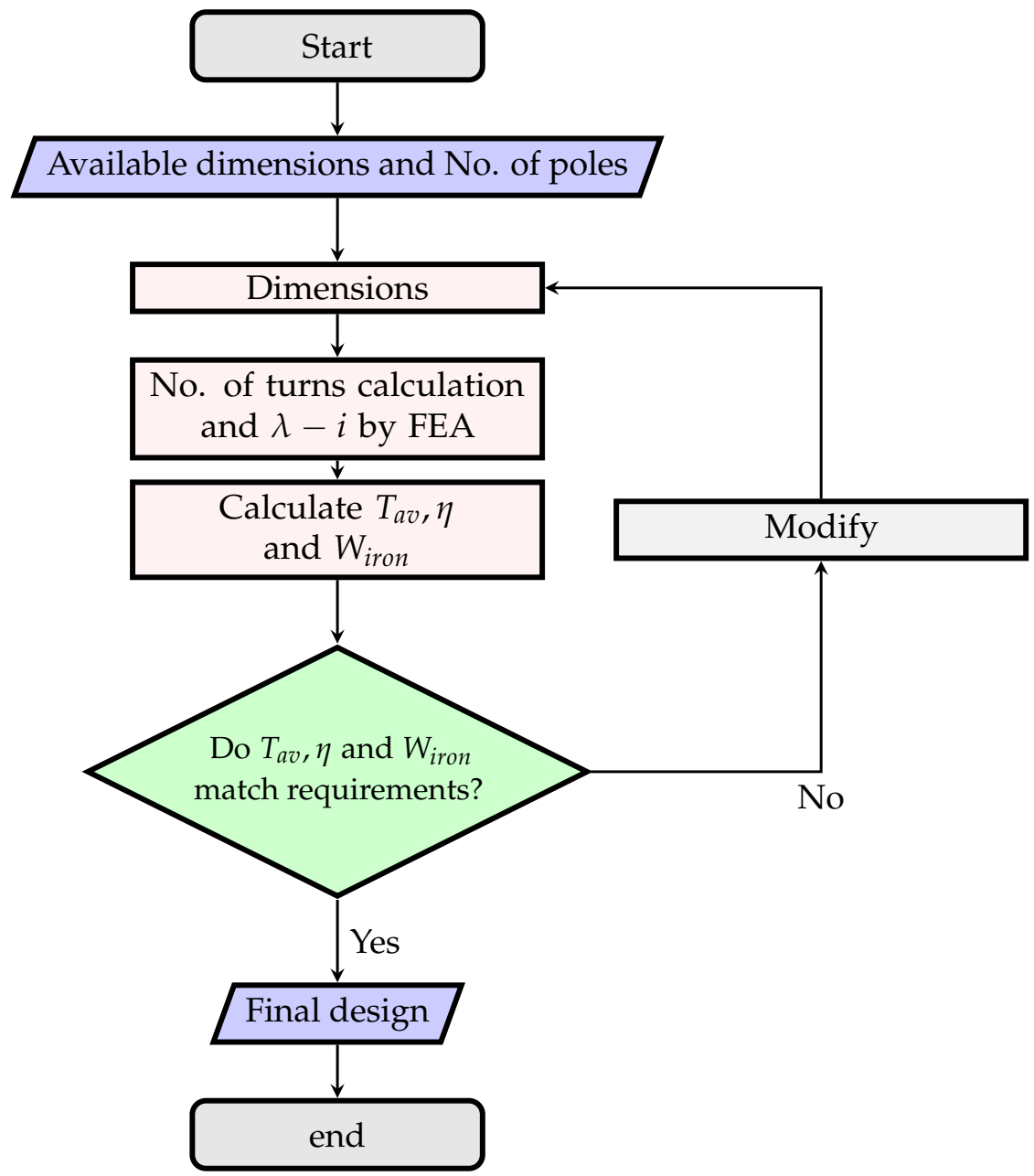
The design procedure of switched reluctance machine starts with specifying the available dimensions from space constraints, for example, frame size, shaft size and axial length then continues until all other dimensions are obtained. The number of stator and rotor poles are specified at the beginning as well. In the conventional analytic design methods, the inductance in the aligned and unaligned is calculated. Using the values of inductances in both aligned and unaligned positions the average torque is calculated. This step is repeated with modified values of the main dimensions until the requirements are justified. The number of turns per phase is calculated for every modification of dimensions such that the flux density doesn’t saturate in stator poles for normal operation. This is demonstrated in
Figure 1. Many other characteristics can be calculated such as efficiency, volume, weight and torque ripple. In this section, the SRM variables are discussed and the methods of characteristics calculations are emphasized.
2.1. Pole Selection
The number of stator poles and the number of rotor poles are usually selected based on previous experience with the application requirements and converter configuration to be used. The combinations of stator and rotor poles are of few choices for good overall design of SRM to be used in general; however, special applications may lead the designer to explore more of less frequent combinations to achieve the application requirements. This paper primarily focuses on the popular combination of 6/4 and 8/6 machines. The 6/4 machine has the advantage of using less switches in the converter, two less terminals and less core losses because of less switching losses than 8/6 machine; however, it has the disadvantage of higher torque ripple than the other common combination of (8/6 machine).
2.2. Rotor and Stator Poles Arcs Selection
Referring to [
2], the minimum stator pole arc to achieve self starting:
The angle between the corners of adjacent rotor poles must be greater than the stator pole arc or there will be an overlap between the stator and rotor poles in the unaligned position. This condition is represented as:
The implication of this condition not being followed is that the machine will start having a positive inductance rate of change before reaching the minimum value. This causes the unaligned inductance value to be higher and leads to a lower torque generation.
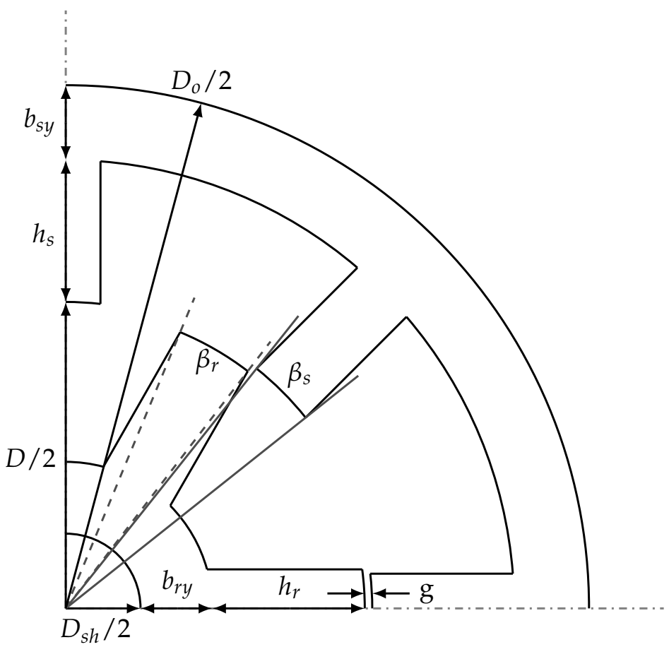
2.3. Main Dimensions
For the dimensions shown in
Figure 2 and
Table 1, the outer diameter (
) is determined by the available space in the application. The shaft diameter (
) is obtained from the shaft’s standard sizes. The outer diameter(
) and (
) are fixed and they are not changed while searching for the suitable design since they are space constraints. However, the axial length (
L) and the bore diameter (
D) can be changed during the design process (Note that the axial length increase is limited by the maximum axial length available in the application). The air gap length(
g) can be changed too but here it is fixed of 0.5 mm. The remaining dimensions are to be changed in order to reach the desired value of torque, efficiency ⋯ and so forth.
2.4. Limits of Variables
The limits of variables depend on the application and the available space. Here, the frame size, shaft diameter, air gap length and axial length are kept constant by making their limits at the same value. The rest of the limits are set by the previous experience.
Table 2 shows the maximum and minimum values of all variables.
2.5. Windings Clearance
The clearance between two adjacent windings is calculated as in [
14]. Taking a wedge of
mm is required to hold the windings in place, the stator pole arc length
at the closest point of the winding to the center of the shaft is given by:
Accounting for the wedges that hold the windings in place leads to the calculation of a modified stator pole pitch
as:
Assuming a suitable value of allowable current density (
), the area of conductor
is calculated. Hence, the wire diameter (
) including insulation is obtained from standards wires tables. The maximum height of the winding (
) is obtained by subtracting a margin length (
) from stator pole height (
):
Assuming
fill factor, the number of layers that can be accommodated in this available winding height is given by:
The value of
is rounded off to the nearest lower integer. Now the number of horizontal layers required for winding is given by:
The space between 2 stator pole tips at the bore is given by:
The width of the winding
is given by:
The clearance between the windings at the bore is given by:
This value has to be positive and preferably greater than 3 mm. Here it is allowed greater than 0.5 mm.
2.6. Average Torque Calculation
Average torque of SRM is calculated based on the assumptions that flux linkage (
) vs. current (
i) characteristics are available and phase current is kept constant at its maximum value between the unaligned and aligned positions [
2].The average torque is the total work done per stroke multiplied by number of strokes of one revolution divided by
:
where
and
are the areas under
curves at aligned and unaligned positions, respectively. W is the area of energy loop and then calculated as in [
22].
2.7. Losses and Efficiency Calculation
The prediction of switched reluctance motor efficiency requires knowledge of losses [
18,
24]. The calculation of losses in the SRM, especially the assessment of core losses, is a very difficult task mainly because the flux waveforms are non-sinusoidal and the differences in shape of flux density waveforms in the different sector of SRM’s magnetic circuit. Furthermore, core losses are also conditioned by the type of control used and rotation speed(
). For low speeds, the mechanical losses can be neglected. Hence losses may be calculated as:
Once the losses are obtained the efficiency is calculated as follows:
In this paper, the speed at which efficiency is calculated is the rated speed of 1000 rpm for all SRM designs candidates. Copper losses value depends on the control technique used as it impacts the value of phase current. Considering n is number of phases,
is phase dc resistance and
is phase current, total copper loss instantaneous value may be calculated by the equation:
The average copper losses can be calculated by equation:
where,
T is the period of time for
strokes. For sake of simplification, we assume no overlap between phases. Since the current of phase is not pure dc. The peak value of it (
) is considered for copper losses calculation as a pessimistic prediction. Copper loss is then calculated straight forwardly by the equation:
2.8. Eddy Currents Losses
Referring to [
25] the eddy current losses in SRM can be calculated by the equation:
where
e: sheet thickness in meter,
: constant (
) introduced to account for the fact that paths in the interior of the lamination will have smaller emfs than those near the surface;
: the electrical resistivity of the ferromagnetic material (in
m);
: density of the ferromagnetic material (in
).
From Equation (
18), the waveform of flux density (
B) for all SRM sectors must be known. Once they are available,
is calculated by numerical integration and differentiation. There are a lot of methods to obtain these waveforms and many of them are time consuming. In [
18], a mathematical method using matrices is introduced to obtain the waveforms of all the SRM sectors in a systematic manner. The calculation of
B waveforms for all sectors is achieved by modulation of triangular pulses. The stator poles waveforms consist only of unipolar triangular pulses, while those of the rotor poles contain both positive and negative pulses. The stator and rotor yoke waveforms have more complicated relationship with the triangular pulses. This method is demonstrated in details in [
18] and used here for 8/6 and 6/4 SRMs.
2.9. Hysteresis Losses
Referring to [
18], the hysteresis losses can be calculated for various sectors of SRM using the following equations:
where:
Referring to [
14], the second formula is used and the constants
are
respectively. The rest of symbols are shown in
Table 3.
The flux density waveforms depend on the phase current waveform and the speed of the motor. Flux density waveforms calculated in this paper rated the speed of 1000 rpm and control is by a single pulse voltage. Hence, it is expected that the resulted designs will have maximum efficiency at 1000 rpm and rated torque average. Note that phase current has the peak of 6 ampere for all SRMs candidates.
3. SRM Design Optimization Techniques
The optimization is a search problem that seeks better objectives. One of the most popular techniques is the genetic algorithm. Wherein, better generations are produced by crossover between the best individuals of the previous generation. To make a decision which is the best, the objective of the optimization problem is needed to be defined. There are two types of optimization, single objective and multi-objective optimization. The decision making criteria is then different, in single objective optimization the criteria is to choose the greater value in the maximization problem to be the best (the smaller for minimization problem). At the end, the best value is considered as the optimal solution.
In the optimization of SRM, the dimensions in
Table 1 represent one possible solution (individual). All individuals information are stored in a vector in suitable data structure.
3.1. Constraints
Since there are several SRM dimensions, there must be certain constraints on them to prevent any non-logical values of variables with non-related physical meanings. The dimensions are checked to satisfy the following constraints:
It is also needed to specify certain limits to each variable (dimension). The maximum and minimum limits are then added to be constraints for all of the variables. If it is needed to keep a certain dimension fixed, this can be simply achieved by setting both the minimum and maximum limits to the desired value.
3.2. Objective Functions
The objectives of SRM optimization depends on the application and its conditions. For general purpose SRM, average torque and efficiency are needed to be maximized and weight is to be minimized. In some applications other objectives (i.e. torque ripples, acoustic noise, vibrations...etc.) are important.
4. NSGA-II for SRM Design Optimization
Non-dominated sorting genetic algorithm (NSGA-II) is one of the best and most popular techniques, which is used in multi-objective optimization problems. It depends mainly on the concept of dominance to judge the individuals of the same generation. This concept takes all of objective functions in consideration with their direction to minimize or maximize. It is required to check each individual with the rest on the dominance basis. As in [
26], assuming
,
are two vector individuals,
m is the number of objective functions, if
(
dominates
) is true, Pareto dominance conditions must all be true and they are:
The non-dominated individual is the individual that is not dominated by any of the other individuals in the population of a certain generation. After that, the individuals are sorted in the form of groups depending on their degree of dominance. These groups are called non-dominated sets or simply fronts. The first front is the group consists of the best (non-dominated) individuals. Multi-objective optimization by NSGA-II eliminates the need of weights in multi-objective optimization by a single function (). Moreover, it eliminates the conflict between weights (as the summation of weights must equal to 1) and hence a wider search area is covered.
Crowding distance is a criterion used to compare between solutions, which are in the same non-dominated front. The more space there is around a solution, the higher is the crowding distance. Therefore, solutions with a high crowding distance should have a rank better than those with a low crowding distance in order to maintain diversity in the population. Crowding distance is computed in the same manner as mentioned in [
26]. Crowding distance is computed for each solution using Equation (
32). If solutions of the same non-dominated fronts are numbered with their associate objective functions in lists, crowding distances are calculated as follows:
where
j is a solution in the sorted list,
is the objective function value of
mth objective,
and
are the population-maximum and population-minimum values of
mth objective functions.
SRM optimization using NSGA-II requires the setting of variables, objective functions, constraints, population size and number of maximum generations. Population size is preferred to be high in order to enhance the possibility of finding better individuals. Since
calculation by FEMM4.2 requires the SRM magnetic circuit to be analyzed several times, the computation time must be taken into consideration while deciding the population size. Hence, population size is chosen to be 30 candidates. A maximum generations number is used as a termination condition. It is chosen to be more than 300 generations. The constraints of the SRM design problem are mainly the limits of variables and the clearance between windings as shown in
Table 2.
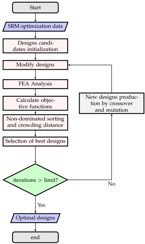
Code Algorithm
The code is made using the Lua programming language. The code is executed using Lua Console in FEMM4.2 software. The choice of the Lua programming language to be used is due to its simplicity and that it is adopted by FEMM4.2, which provides the FEA analysis in good accuracy. The code’s algorithm is shown in
Figure 3. First, SRM optimization data are entered. These data include the population size, problem variables, variables limits, objective functions, to specify which objective function to maximize and which to minimize the maximum iterations limit and numbers of rotor and stator poles (
and
). Then, solutions are initialized by random choice of variables within the search space area. After that, constraints in Equations (
26)–(
29) are maintained in this step by changing the values of variables resulted. Then, the FEA is accomplished using FEMM4.2 software to calculate average torque, maximum stator and rotor poles flux densities and volume of iron. After that, the results of FEA analysis is used to calculate the remaining objective functions (
and
). Then, non-dominated sorting is performed and crowding distance is calculated for all solutions. Next, the selection of the best designs to be used in crossover and mutation. Lastly, termination condition is checked such that if number of iterations exceeds the maximum limit the whole process is finished and the highest rank of all solutions (non-dominated front) is the given in the output of optimization process.
5. Results and Discussions
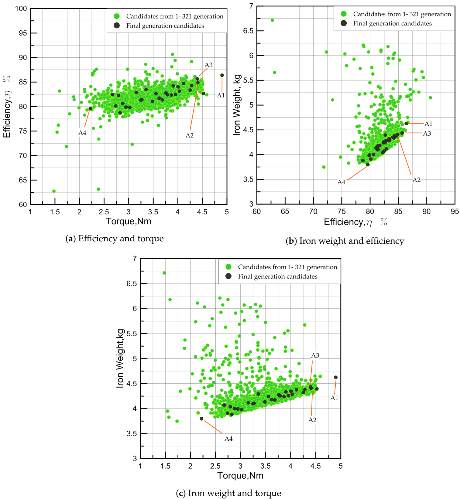
Both 6/4 and 8/6 SRMs are optimized using the same technique. Since there are three objective functions, it is difficult to show them all together in one figure to see the progress of the optimization process with generations. Hence, the objective functions are taken in pairs and shown as in
Figure 4 for 8/6 SRM and
Figure 5 for 6/4 SRM for more than 300 generations.
These figures show the search direction or the optimization progress as more generations are produced. As we intended to maximize both average torque and efficiency and minimize iron weight, it is obvious that the crowded area (which indicates the majority of search) in
Figure 4a, for example, exists in the upper right quarter (considering the axes limits). Wherein, higher values for both efficiency and average torque are sought. This means that the optimization program has searched a lot in the area of variables that produce candidates with more average torque and efficiency in the same time.
Figure 4b shows the same concept with the difference that the objective functions are iron weight and efficiency. The program tries to minimize iron weight while maximizing efficiency but because of the complexity of the problem and the constraints, results have a unique shape. The program tries to achieve better candidates by searching right or left of the crowded area. The same goes for
Figure 4c, replacing the efficiency in
Figure 4b with average torque. For 6/4 SRM, the results represented by
Figure 5 show the same features of optimization as in 8/6 SRM.
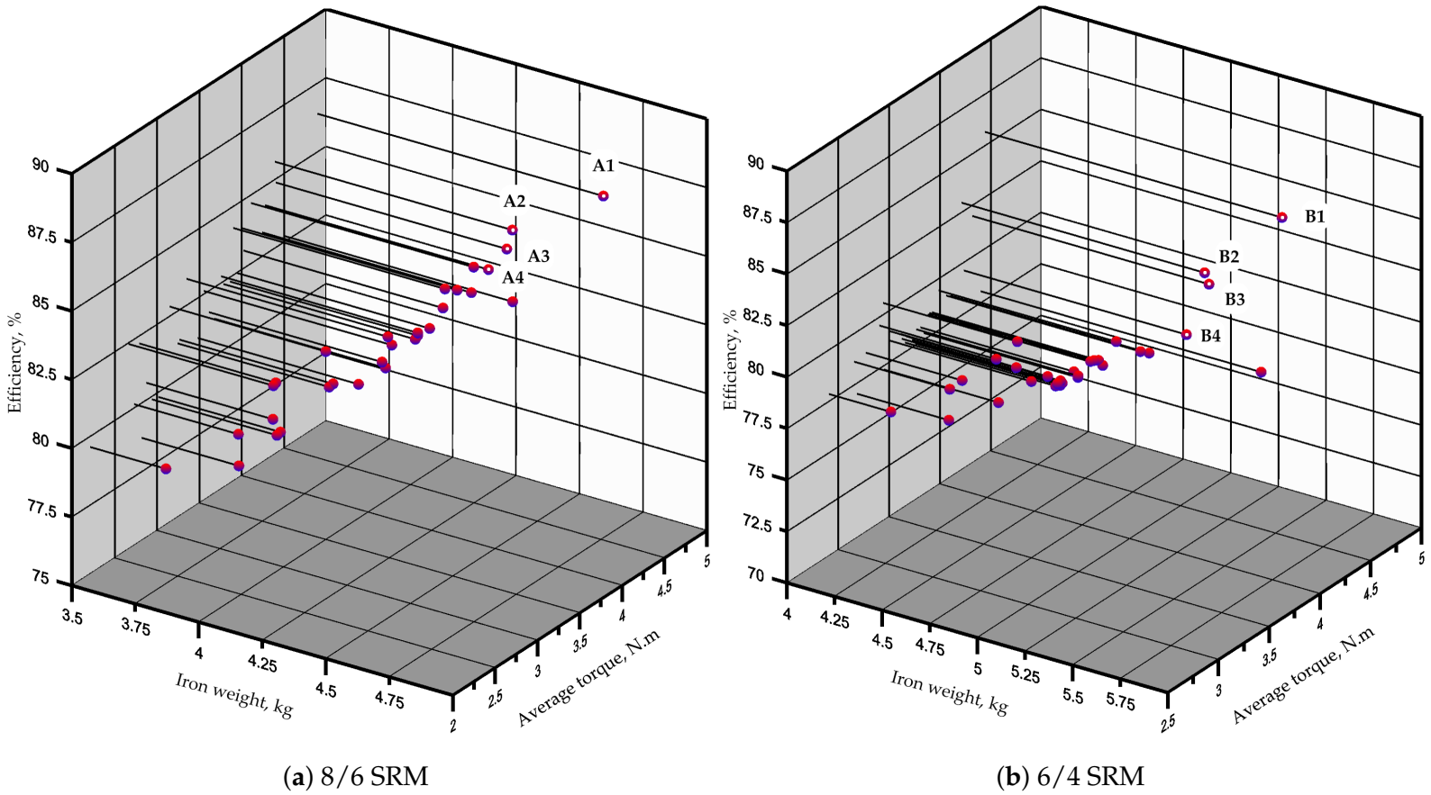
Figure 6 shows the candidates of final generation with the three objective functions. The results shown confirm the accuracy of the search direction. Moreover, it indicates the diversification of the method used as it shows variety in objective functions’ values.
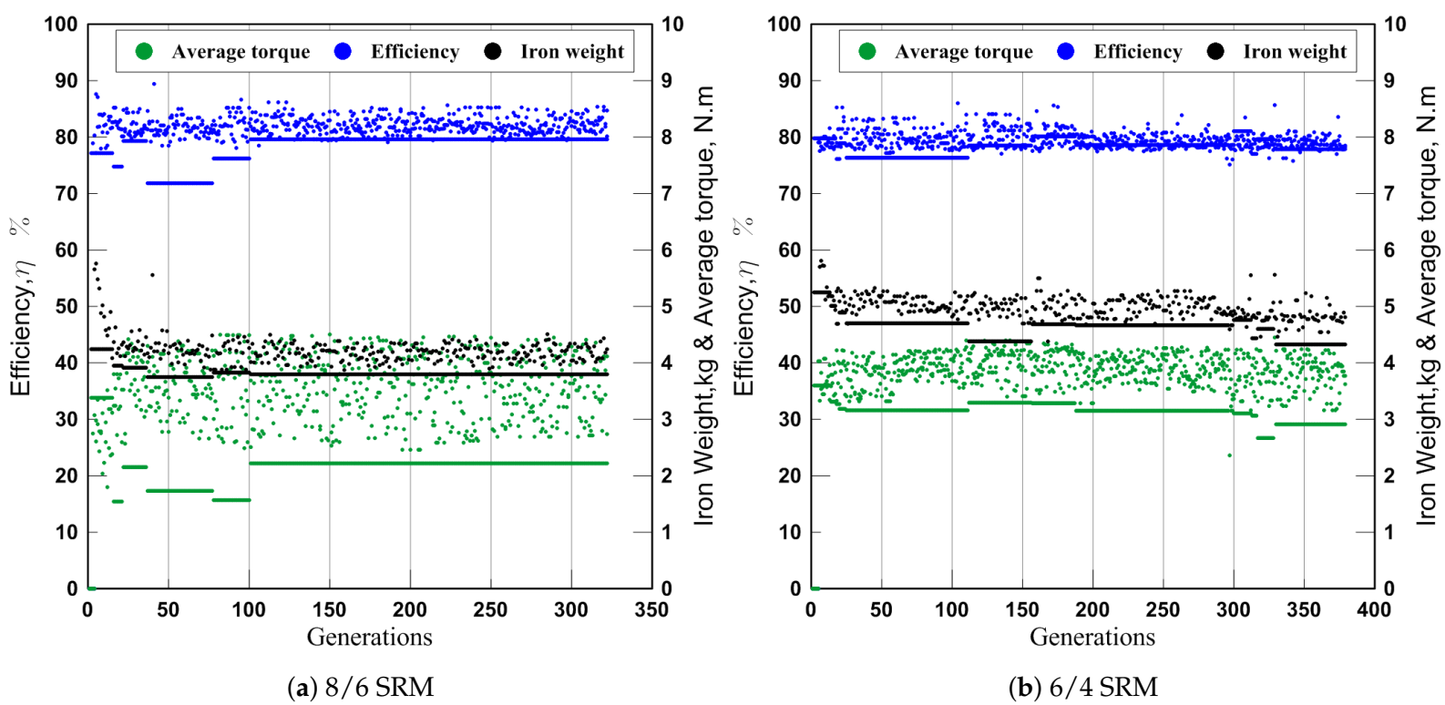
The progress of optimization with generations for both 8/6 SRM and 6/4 SRM is shown in
Figure 7. It can be seen that average torque and efficiency are maximized as more generations are produced and the iron weight is minimized at the same time.
Table 4 shows the best selected candidates among the first non-dominated front (also known as rank 1). Four candidates are selected for each configuration (set A for 8/6 SRM and B for 6/4 SRM). A1 and B1 achieve the maximum values of average torque and efficiency among the final generation candidates. A4 and B4 achieve the minimum iron weight. A2, A3, B2 and B3 are compromise designs, which satisfy each objective function in a certain degree. A1 and B1 designs are selected from these candidates for further investigation. All designs of the selected sets in
Table 4 are shown in
Figure 4,
Figure 5 and
Figure 6. The values of objective functions, parameters, dimensions and other details for selected sets are shown in
Table 5. From
Table 5, it can be seen that the variation of dimensions to produce better designs matches with the SRM design experience, which indicate the accuracy of calculation methods. For example, the difference between aligned inductance (
) and unaligned inductance (
) is higher in designs of higher average torque. This result matches with design experience as the energy conversion increases with higher difference of flux level between aligned and unaligned positions. This is indicated by Equation (
12). Other important observations indicated in
Table 5 should be highlighted and they are:
For the same axial length wider rotor and stator poles result in higher flux. Hence, higher average torque. This is observed by values of , and for all selected designs.
Higher torque densities are achieved by 8/6 configuration (A) due to their higher number of phases and, hence, average torque.
Efficiencies values are calculated for all candidates at 1000 rpm, which is a relatively low speed. Hence, there is not much of a difference between iron losses of 8/6 (A) and 6/4 (B) configurations. However, B1 design is proven to give higher efficiency values than that of A1 for a wide range of speeds as will be provided later. The same can be indicated for all designs of sets A and B by all meaning that designs in set B (6/4 SRM) would have higher efficiency values than those in set A (8/6 SRM) for higher values of speeds.
Number of turns and inductance values are higher in B (6/4 SRM) due to wider stator and rotor poles as the same flux density is assumed for both.
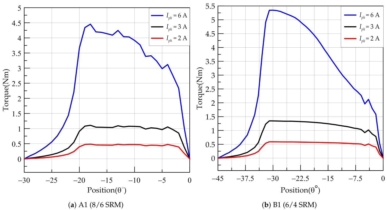
Further investigations are made on the selected designs A1 and B1. The torque is shown in
Figure 8 for constant phase current from an unaligned position to aligned positions for selected optimal designs. Note that the peak torque for B1 (6/4 SRM) is higher than that of A1 (8/6 SRM) due to the higher difference between aligned and unaligned inductances in 6/4 SRM. However, the average value of A1 (8/6 SRM) torque is higher than that of B1 (6/4 SRM) due to the increased number of phases in 8/6 SRM configurations.
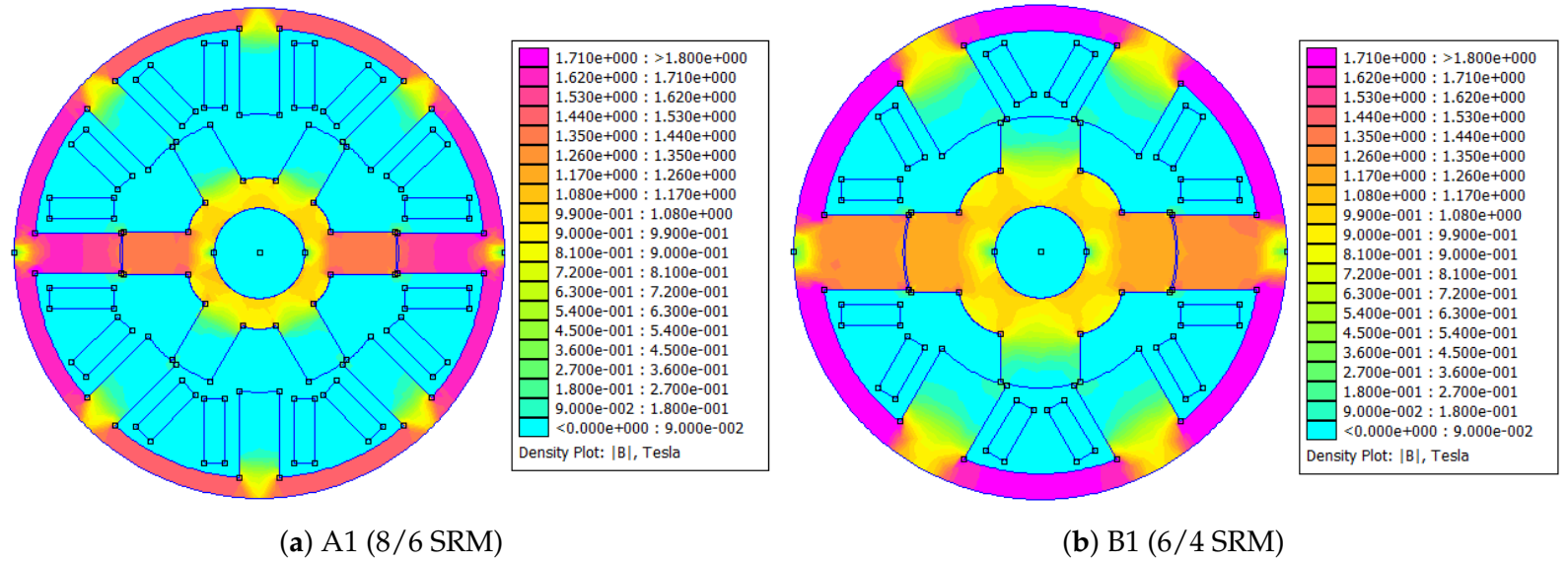
Figure 9 shows the magnetic flux of both selected designs. It can be seen that the value of flux density in the stator pole is about 1.8 T, which represents the knee point of B-H curve for industrial steel used. The stator yoke flux density is obviously higher than stator flux density for 6/4 SRM. This is because the stator yoke thickness does not impact the objective functions strongly, that is, it can be neglected. Hence, the optimization program tends to decrease it to a minimum to get less weight of iron. To achieve a good overall SRM design, other objective functions must be added such as torque ripples, acoustic noise … and so forth. When these functions are added, the program will not reduce the stator yoke thickness to a minimum as it influences other objective functions negatively (increases acoustic noise for example).
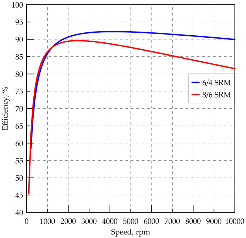
In
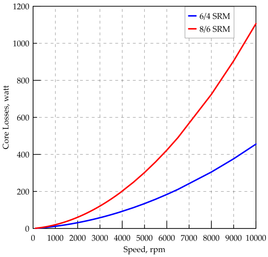
Figure 10, the efficiency of optimal selected designs for a range of speeds up to 10th of rated speed is shown. It can be seen that the values of efficiency for selected optimal designs are almost identical to the value of speed before 1300 rpm. This result is due to the lower core losses in this region as shown in
Figure 11. The program was given the rated speed of 1000 rpm to calculate core losses and efficiency and then seek better values at same speed. It can also be seen that 6/4 SRM has a better efficiency profile than 8/6 SRM over a wide speed range, which is expected due to higher core loss values as demonstrated in [
14]. SRM with 8/6 configuration has a higher number of poles than 6/4 SRM and hence flux changes are higher, which leads to core losses.
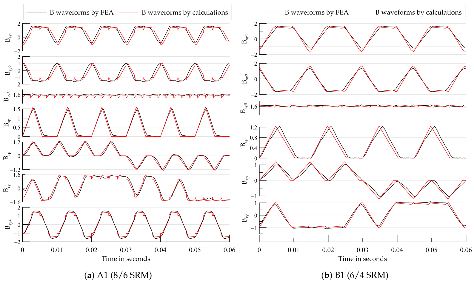
Figure 11 shows the core losses of 8/6 SRM is much higher than that of 6/4 SRM.
Figure 12 shows a comparison between calculated and FEA waveforms of flux density (
B) of all sectors for the chosen optimal designs. It can be seen that the results of the calculation are very close to FEA waveforms. The calculation method is used to produce flux density (
B) waveforms and to then calculate eddy currents losses as introduced in
Section 2.8.
The proposed techniques in [
16,
17,
20,
27] are considered for the evaluation of the methodology presented by this paper, as they studied the same SRM configurations or multi objective optimization. The methodology presented in this paper achieves high accuracy in analysis due to the use of FEA. The optimization technique performance has also shown successful progress towards the optimal. In [
17], the same technique is used for a specific application. The values of efficiency and torque density are higher than what is presented in this paper. This is due to the generality of the approach in this paper. The approaches in [
20,
27] are general, however, they use mathematical models in analysis to reduce computational time, which makes the process more complex and needs more analytic work before optimization starts. For torque density values, [
27] achieves 1200–1580 N.m/m
while [
17] reached 15,950–17,030 N.m/m
. In this paper, torque densities of 7780–8315 N.m/m
and 6238–6473 N.m/m
are achieved for 8/6 and 6/6 configurations, respectively. Efficiency values are 75%–80%, 86%–91% and 80%–85% in [
17,
20,
27], respectively, while in this paper efficiency values of 80%–86% are achieved for most of the design candidates. The approach proposed in this paper has shown success in optimization, as objective function values indicate. Also, it can be used for almost any application if the suitable objective functions are added.


