Article

Hybrid Carbon Nanotube Flow near the Stagnation Region over a Permeable Vertical Plate with Heat Generation/Absorption

1
Faculty of Computer and Mathematical Sciences, Universiti Teknologi MARA, Shah Alam 40450, Selangor, Malaysia
2
Department of Mathematics & Statistics, Faculty of Science, Universiti Putra Malaysia, Serdang 43400, Selangor, Malaysia
3
Institute for Mathematical Research, Universiti Putra Malaysia, Serdang 43400, Selangor, Malaysia
4
Department of Mathematics, Babes-Bolyai University, 400084 Cluj-Napoca, Romania
*
Author to whom correspondence should be addressed.
Mathematics 2021, 9(22), 2925; https://doi.org/10.3390/math9222925
Submission received: 30 August 2021 / Revised: 29 September 2021 / Accepted: 9 October 2021 / Published: 17 November 2021

Abstract

:
This research explored the mixed convection flow past a vertical plate immersed in a hybrid carbon nanotube near the stagnation point. The hybrid carbon nanotube was synthesized by the mixture of two nanoparticles, namely multi-wall (MWCNT) and single-wall (SWCNT) carbon nanotubes immersed in water (base fluid). In addition, attractive aspects of suction/injection and heat generation/absorption effects were incorporated. Similarity variables were used to convert the partial differential equations describing the fluid into ordinary (similarity) differential equations before being solved numerically using Matlab software. The simultaneous impact of several parameters on velocity and temperature profiles, skin friction coefficient, and local Nusselt number were represented with graphs. Dual solutions were observed for some pertinent parameters, which led to stability analysis. This analysis interpreted that merely the first numerical solution is stable. In addition, hybrid nanoparticle, injection effect, and heat-generation parameters led to a decreased range of solutions, whilst the suction effect and heat-absorption parameters acted in the opposite manner. Besides, it is noted that the rate of heat transfer for hybrid carbon nanotube was higher when compared with carbon nanotube and ordinary fluid. Additionally, the heat absorption and buoyancy-assisting flow parameters magnified the heat transfer rate.

1. Introduction

Many researchers are fascinated by nanofluid (i.e., mixing nanoparticles in the base fluid) due to its rapid advancement in nanotechnology and modern sciences. The work of Choi and Eastman [1] showed that copper nanoparticle helps enhance heat-transfer efficiency. Owing to their captivating convective thermal properties, nanofluids have been identified as potential thermofluids for future applications [2,3]. Compared with ordinary nanofluids, hybrid nanofluids (i.e., the mixture of two diverse nanoparticles in a base fluid) provide highly efficient thermal energy transfer. In an experimental investigation by Suresh et al. [4], they found that a 2% volume fraction of hybrid nanocomposites (Al2O3–Cu) in water caused a 12.11% increase in thermal conductivity. Afterwards, Takabi and Salehi [5] and Devi and Devi [6] conducted a numerical investigation on hybrid nanofluid with suspended nanoparticles (alumina and copper) in water (base fluid), and they showed that when compared with ordinary nanofluid, the heat-transfer rate of hybrid nanofluid produces an outstanding result. The idea of using hybrid nanofluid then flourished, attracting several researchers to study the thermal behavior of some nanoparticles such as metallic [7,8], ferrite [9,10], and carbon nanotube [11,12] in fluid flow through various surfaces and effects. However, research related to hybrid nanofluids that use carbon nanotubes (i.e., MWCNT and SWCNT) as nanoparticles is limited. Since Iijima’s [13] discovery of carbon nanotubes, carbon-based nanotechnology has promptly developed as a platform technology for a wide range of applications, including biomedicals [14,15], wastewater treatments [16,17], and electronics [18,19]. As a result, the primary goal of this research was to investigate the behavior of MWCNT and SWCNT in the base fluid water.
Many technical and industrial applications use mixed convection flow (i.e., the simultaneous presence of free and forced convection flow). Examples of such applications are heat exchangers, nuclear reactors, solar central receivers, and electronic devices [20]. Mixed convection is induced by the motion of solid material, such as the suction/injection effect (forced convection) and buoyancy force generated by the heated vertical wall (natural convection). Injection or suction of fluid through the bounding surfaces can drastically alter the flow field and, as a result, affect the rate of heat transfer. Work on suction/injection in a vertical plate includes the study of Ishak et al. [21]. Their results showed that two solutions exist for assisting and opposing flow: injection delays the separation of the boundary layer while suction fastens in. This research was then continued by Ishak et al. [22] with an additional effect of magnetohydrodynamic (MHD), Tamim et al. [23] for MHD nanofluid flow, and by Rostami et al. [24] in aqueous silica-alumina hybrid nanofluid. In another work, Ghalambaz et al. [25] performed the stability analysis on hybrid nanofluid (Al2O3-Cu/water) in a vertical permeable plate and showed that the first solution is always a stable solution. It should be pointed out that most of these researchers consider their investigation near the stagnation point (i.e., the fluid flow near a circular body’s stagnation region, which occurs in both fixed and moving bodies in a fluid) owing to its practical applications and numerous applications in the industry [26].
In this research, the use of heat generation (source) and absorption (sink) may have a crucial impact on the heat transfer characteristics and optimize the fluid flow. These effects are essential in cooling problems associated with nuclear reactions, combustion processes, and neurobiology (in the study of the human brain function) [27]. Some important investigations concerning the heat source or sink impact in boundary layer flow were made by Bhattacharyya [28], Ahmed et al. [29], Makinde et al. [30], and Agrawal et al. [31]. A detailed study covering the heat generation/absorption influence on MHD radiative porous vertical moving plate was conducted by Anwar et al. [32]. In their investigation, they discovered that increasing values of heat sink parameter reduces the rate of heat transfer. In very recent work, Reddy et al. [33] considered the influence of heat source/sink on MHD flow when it is stretched exponentially through a porous medium and demonstrated that the local Nusselt number rises as the value of heat source increases due to the increased amount of heat energy stored.
In several boundary layer flow problems, the existence of two or more solutions is another interesting flow phenomenon. The researchers have started performing and breaking down the results in the last two or three decades, which have non-unique solutions. The occurrence of non-unique solution is due to several physical parameters’ impacts, such as mixed convection parameter, suction parameter, shrinking parameter, and moving (opposing flow to the free stream) parameter. Usually, the first solution is represented by the solid line or upper branch solution, while the second solution is represented by the dash line or lower branch solution.
According to the work cited earlier, the topic of hybrid carbon nanotube (using SWCNT and MWCNT as nanoparticles) in permeable vertical plates has not been thoroughly investigated up until now. Therefore, this paper extends the research done by Ghalambaz et al. [25] by introducing an additional parameter heat generation or absorption parameter in a hybrid carbon nanotube. With the aid of similarity transformations, we will use bvp4c in Matlab to solve the ordinary differential equations derived from the governing boundary layer equations. Surprisingly, the current research revealed the occurrence of non-unique solutions, and thus the stability analysis initiated by Merkin [34] was carried out. The stability analysis of non-unique solutions has attracted much attention from researchers because of the different behavior of the solutions in temperature and velocity profiles. This kind of analysis is essential to avoid any misleading interpretation of flow. Hence, many researchers (see Refs. [35,36,37,38]) have mathematically performed the stability analysis of solutions in their recent work. Furthermore, this theoretical study would benefit engineers who are conducting experiments on hybrid carbon nanotubes, and the findings are expected to lower the cost of future experiments.

2. Mathematical Analysis

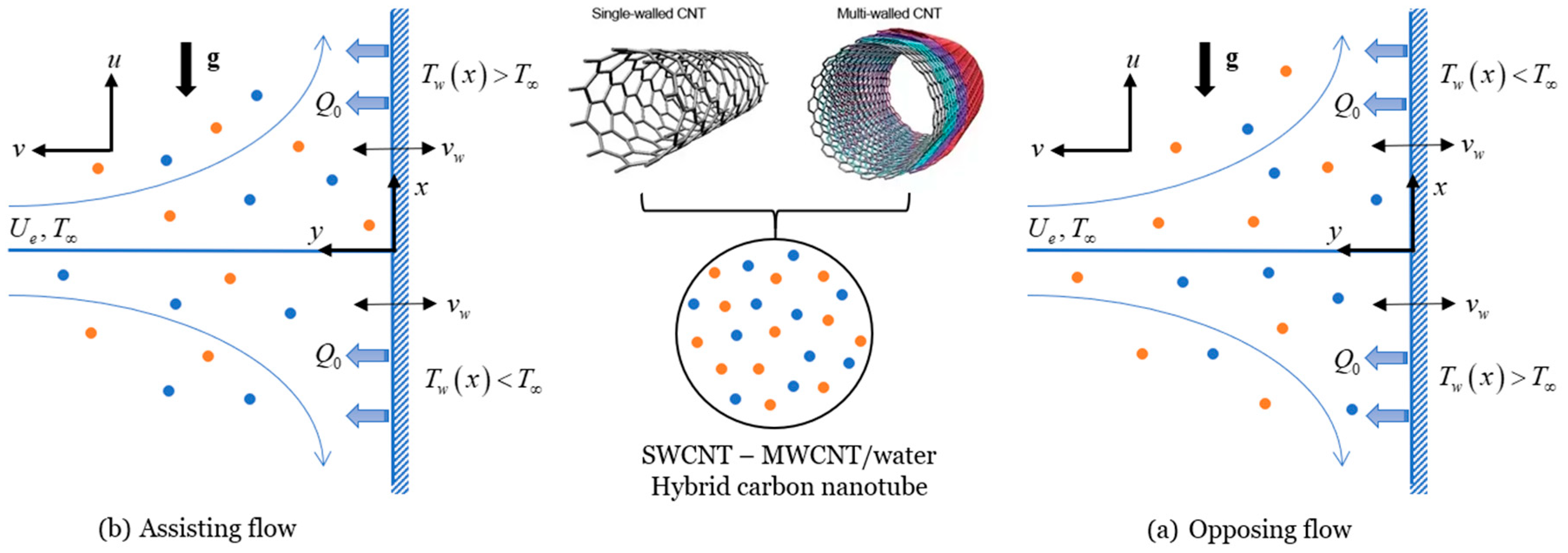
2.1. Flow Formulation

Let us investigate the steady hybrid carbon nanotube flow near the stagnation region towards a permeable vertical plate in the existence of heat generation/absorption. In the present research, a hybrid carbon nanotube (SWCNT–MWCNT/water) was formed by dispersing 1% of multi-wall carbon nanotube (MWCNT) nanoparticles into the base fluid (water). Then, the single-wall carbon nanotube (SWCNT) is scattered in MWCNT/water nanofluid to produce the targeted hybrid carbon nanotube. In addition, the inviscid flow velocity is U e ( x ) = a x , where a ( > 0 ) is the stagnation point’s velocity, while the sheet’s temperature is T w ( x ) = T + b x , given that T is the ambient fluid at a constant temperature and b is a constant. Both heating ( T w ( x ) > T ) and cooling ( T w ( x ) < T ) of the sheet are considered, which correspond to assisting and opposing flows, respectively. The assisting flow ( b > 0 ) situation takes place if the lower half of the plate surface is cooled and the upper half of the plate surface is heated. Nevertheless, opposing flow ( b < 0 ) takes place in the opposite manner. The buoyancy force is caused by temperature variance in the fluid; meanwhile, a heat generation or absorption is situated within the flow to allow for heat source or sink effects. To model the present problem, a Cartesian coordinate system ( x , y ) is chosen in such a way that the plate is parallel along the x -axis, and therefore, the y -axis is perpendicular to it, the flow being at y 0 , as illustrated in Figure 1.
The modelled equations for the steady flow of incompressible water-based hybrid carbon nanotube can be expressed as (see Refs. [6,25]):
u x + v y = 0 ,
u u x + v u y = U e U e x + μ h c n t ρ h c n t 2 u y 2 + β h c n t g ( T T ) ,
u T x + v T y = k h c n t ( ρ C p ) h c n t 2 T y 2 + Q 0 ( ρ C p ) h c n t ( T T ) ,
associated with its conditions:
u = 0 , v = v w , T = T w ( x ) at y = 0 , u U e ( x ) , T T as y
where the velocity components in x - and y -direction are given by u and v , respectively, T is the temperature of the fluid, Q 0 is the uniform volumetric heat source/sink, g is the acceleration due to gravity, and v w is the mass-transfer velocity.
Further, μ refers to the dynamic viscosity, β is the coefficient of thermal expansion, ρ is the density, ρ C p and k denote the heat capacity and thermal conductivity, respectively, where the subscript h c n t refers to the hybrid carbon nanotube. The following thermo-physical characteristics for hybrid carbon nanotube are given in Table 1 (see Takabi and Salehi [5]).
Here, φ is the summation of the volume concentration of two dissimilar kind of nanoparticles, i.e., φ = φ 1 + φ 2 where the subscripts ‘1’ and ‘2’ stand for the first and second nanoparticles, respectively. In addition, the subscript f and h p denote the base fluid and hybrid particle. It should be emphasized that the first nanoparticle is denoted by MWCNT while the second nanoparticle refers to SWCNT. Here, the volume fraction of SWCNT nanoparticle fluctuates from 0% to 2%. The physical characteristics of the nanosized particles and the base fluid are shown in Table 2 (see Aman et al. [39]).
Further, we define the following transformation:
ψ = a ν f x f ( η ) , η = a ν f y , θ ( η ) = T T T w ( x ) T
where ν f , f , θ , and η refer to the kinematic viscosity, dimensionless velocity, dimensionless temperature, and similarity variable, respectively. ψ is the stream function, which helps to transform velocity components in the form of dimensionless parameter and defined in the usual way as u = ψ / y and v = ψ / x . So that:
u = a x f η , v = a ν f f
On using Equations (5) and (6), the continuity equation, i.e., Equation (1), is identically satisfied. Now, Equations (2) and (3) are reduced to:
μ h c n t / μ f ρ h c n t / ρ f f η η η f η 2 + f f η η + β h c n t β f λ θ + 1 = 0
1 ( ρ C p ) h c n t / ( ρ C p ) f ( k h c n t / k f Pr θ η η + Q θ ) + f θ η f η θ = 0
Conditions (4) give:
f ( 0 ) = s , f η ( 0 ) = 0 , θ ( 0 ) = 1 θ ( η ) 0 , f η ( η ) 1 as η
From the above equations, Pr ( = μ f ( C p ) f / k f ) is the Prandtl number, λ ( = G r x / Re x 2 ) denotes the mixed convection parameter with λ > 0 , and λ < 0 represents the assisting and opposing buoyancy flow where G r x ( = g β f ( T w ( x ) T ) x 3 / ν f 2 ) and Re x ( = U e ( x ) x / ν f ) are the Grashoff number and Reynold number, respectively, Q ( = Q 0 / ( a ( ρ C p ) f ) ) is the heat sink ( Q < 0 ) or source ( Q > 0 ) parameter and s ( = v w / a v f ) is the injection ( s < 0 ) or suction ( s > 0 ) parameter.

2.2. Physical Quantities

The skin friction and Nusselt number are defined as:
C f = μ h c n t ( u y ) y = 0 ρ f U e 2 , N u x = x k h c n t ( T y ) y = 0 k f ( T w T )
By the aid of similarity transformation of Equation (5) and using Equations (6) and (10), one obtains:
C f Re x 1 / 2 = μ h c n t μ f f ( 0 ) , N u x Re x 1 / 2 = k h c n t k f θ ( 0 )
where prime is the differentiation with respect to η .

2.3. Stability Analysis

The existence of more than one solution led us to dictate which of these solutions is the stable solution. To perform this analysis, the unsteady governing equations were considered as:
u t + u u x u x + v u y = U e t + U e U e x + μ h c n t ρ h c n t 2 u y 2 + β h c n t g ( T T ) ,
T t + u T x + v T y = k h c n t ( ρ C p ) h c n t 2 T y 2 + Q 0 ( ρ C p ) h c n t ( T T ) ,
which correspond to its boundary condition:
t < 0 : v = u = 0 , T = T for   any x , y t 0 : v = v w , u = 0 , T = T w ( x ) at y = 0 , u U e ( x ) , T T as y
where t refers to time. The following new transformation in the presence of time variable τ for the above time dependent problem are introduced:
ψ = a ν f x f ( η , τ ) , η = a ν f y , θ ( η , τ ) = T T T w ( x ) T , τ = a t
Implementing the new transformation given in Equation (15) into Equations (12)–(14), we obtain:
μ h c n t / μ f ρ h c n t / ρ f f η η η + f f η η ( f η ) 2 + 1 + β h c n t β f λ θ f τ η = 0
1 ( ρ C p ) h c n t / ( ρ C p ) f ( k h c n t / k f Pr θ η η + Q θ ) + f θ η f η θ θ τ = 0
together with conditions:
f ( 0 , τ ) = s , θ ( 0 , τ ) = 1 , f η ( 0 , τ ) = 0 θ ( η , τ ) 0 , f η ( η , τ ) 1 as η
Next, the following equations are used to detect the stability of the flow [40]:
θ ( η , τ ) = θ 0 ( η ) + e γ τ H ( η , τ ) , f ( η , τ ) = f 0 ( η ) + e γ τ F ( η , τ )
where H ( η , τ ) and F ( η , τ ) are small relative disturbances to θ 0 ( η ) and f 0 ( η ) , respectively, and γ is the unknown eigenvalue parameter. Using Equation (19) into (16), (18) and letting τ 0 , in which H ( η ) = H 0 ( η ) and F ( η ) = F 0 ( η ) , we have the following linearized equation:
μ h c n t / μ f ρ h c n t / ρ f F 0 + f 0 F 0 + F 0 f 0 2 f 0 F 0 + β h c n t β f λ H 0 + γ F 0 = 0
1 ( ρ C p ) h c n t / ( ρ C p ) f ( k h c n t / k f Pr H 0 + Q H 0 ) + f 0 H 0 f 0 H 0 + γ H 0 + F 0 θ 0 F 0 θ 0 = 0
and conditions (18) become:
F 0 ( 0 ) = 0 , F 0 ( 0 ) = 0 , H 0 ( 0 ) = 0 , F 0 ( η ) 0 , H 0 ( η ) 0 as η
Following the work of Harris et al. [41], one of the boundary conditions need to be relaxed. Hence, we replaced condition F 0 ( η ) 0 as η with the new condition F 0 ( 0 ) = 1 .

3. Analysis of Results

The ordinary differential Equations (7)–(9) were solved through numerical technique bvp4c in Matlab. Equations (7) and (8) reduce to those obtained by Ghalambaz et al. [25] in the omission of heat generation or absorption effect. The current results obtained are validated with Ramachandran et al. [42] and Ghalambaz et al. [25] in the absence of hybrid nanoparticles ( φ = 0 ) , suction/injection ( s = 0 ) , and heat source/sink ( Q = 0 ) as given in Table 3 and Table 4. The current findings are confirmed to be in good agreement with the results of Ramachandran et al. [42] and Ghalambaz et al. [25]. As a result, the proposed mathematical model can be used confidently to scrutinize the fluid flow and heat transfer of the current problem. Throughout this study, nanoparticle volume fraction ( φ 1 , φ 2 ) are taken over the range of 0 φ 1 , φ 2 0.02 , heat source/sink parameter ( Q ) over the range of 0.1 Q 0.1 , the values of mixed convection ( λ ) are taken over the range of λ c λ 4 where λ c is the bifurcation point (critical value) and the Prandtl number Pr is fixed to 6.2 (water), except for comparisons to the previous study. Furthermore, the value of s is set to 0.2 for suction, 0.2 for injection, and 0 for the impermeable case.
This section discusses the various outcomes of the current study, which are depicted graphically in Figure 2, Figure 3, Figure 4, Figure 5, Figure 6, Figure 7, Figure 8, Figure 9, Figure 10, Figure 11, Figure 12, Figure 13 and Figure 14. The behavior of the SWCNT nanoparticle φ 2 for s = 0.2 (suction) and s = 0.2 (injection) on the velocity f ( η ) and temperature θ ( η ) fields are displayed in Figure 2 and Figure 3. The conditions at infinity (9) are clearly verified by these figures. This demonstrates the correctness of our results for the boundary-value problem (7)–(9). Clearly, f ( η ) is declining against the increasing value of φ 2 while θ ( η ) is enhanced with it for first and second solutions. Here, the solid line represents the first solution, whereas the second solution is given by the dash line. Additionally, from this figure, it is noticed that the presence of suction effect (red line) results in the decreasing of momentum and thermal boundary layer thickness while the injection effect (blue line) does contrary.
Figure 4, Figure 5, Figure 6 and Figure 7, in turn, illustrate the variation of C f Re x 1 / 2 (skin friction coefficient) and N u x Re x 1 / 2 (local Nusselt number) with λ (mixed convection parameter) in the existence of heat generation ( Q = 0.1 ) for selected values of the nanoparticle volume fraction ( φ 1 and φ 2 ) when s = 0.2 (Figure 4 and Figure 6) and s = 0.2 (Figure 5 and Figure 7). From these figures, two numerical solutions were observed for assisting flow ( 0 < λ 4 ) and opposing flow ( λ c < λ < 0 ) , where λ c is the bifurcation point in which the second and first solutions intersect. In contrast, no solution was discovered when λ < λ c , whereas one solution was obtained when λ = λ c . It is spotted that the bifurcation points for SWCNT–MWCNT/water hybrid carbon nanotube ( φ 1 = φ 2 = 0.01 ) are λ c = 4.55435 (suction) and λ c = 2.04779 (injection), while the bifurcation points for MWCNT/water nanofluid ( φ 1 = 0.01 , φ 2 = 0 ) are λ c = 4.87471 (suction) and λ c = 2.05397 (injection). Additionally, in the absence of nanoparticle volume fraction ( φ 1 = φ 2 = 0 ) , the bifurcation points λ c are 5.25952 (suction) and 2.06981 (injection). It was thus confirmed that the hybrid nanoparticle influenced the acceleration of the boundary layer separation. Furthermore, the presence of suction effect in the flow could hinder the separation of the boundary layer, whereas injection effect facilitates it. Further, it was discovered that N u x Re x 1 / 2 and C f Re x 1 / 2 increases with an upsurge value of nanoparticle volume fraction except when λ approaches its bifurcation point for the first solution. This implies that hybrid carbon nanotube acts better in the cooling process than MWCNT/water nanofluid and ordinary fluid. Besides, the graphical behavior also shows that assisting flow ( λ > 0 ) tends to offer higher values of C f Re x 1 / 2 and N u x Re x 1 / 2 compared to opposing flow ( λ < 0 ) . This is explained by the fact that in the assisting flow, buoyancy force behaves as a favorable pressure gradient, causing the flow to accelerate and, as a result, there is a faster heat transfer rate and larger skin friction coefficient than in the opposing case.
The f ( η ) (velocity) and θ ( η ) (temperature) fields with some values of Q ( = 0.1 , 0 , 0.1 ) for the suction and injection effects in SWCNT–MWCNT/water hybrid carbon nanotube have been displayed in Figure 8 and Figure 9, respectively when λ = 1 (opposing flow). It is shown in the figure that for the first solution, the transition from Q = 0.1 (heat absorption) to Q = 0.1 (heat generation) enhanced the momentum and thermal boundary layer thickness, whilst the contrary manner is observed for the second solution. From the definition of Q , the rise of the internal heat of fluid will directly enhance the kinetic energy and thus fluid flow. In addition, it was discovered that the first solution and presence of suction possess thinner boundary layer thicknesses relative to the second solution and presence of injection.
Next, the behavior of Q (transition from heat absorption to heat generation) on C f Re x 1 / 2 (skin friction coefficient) and N u x Re x 1 / 2 (local Nusselt number) in the existence of suction (Figure 10 and Figure 12) and injection (Figure 11 and Figure 13) were analyzed. Once again, it is clearly seen that dual solution exists for opposing ( λ c < λ < 0 ) and assisting flow ( 0 < λ 4 ) . Surprisingly, the boundary layer separation is affected by the occurrence of heat generation or absorption. The bifurcation points are λ c = 5.41800 ,   4.97950 and 4.55435 for Q = 0.1 , 0 and 0.1 in the presence of suction, whilst in the presence of injection, the bifurcation points are λ c = 2.57420 , 2.30529 and 2.04779 . Hence, it is proved that heat absorption and the presence of suction in the flow could delay the boundary layer separation. Besides, upsurge values of Q causes the values of C f Re x 1 / 2 to enhance for λ > 0 but depreciate for λ < 0 , whereas the values of N u x Re x 1 / 2 depreciate for all range of λ in the first solution. The heat generation process generates a layer of hot fluid near the surface, and the fluid’s temperature eventually exceeds the surface temperature, causing a decline in the rate of heat transfer from the surface.
It should be pointed out that the two solutions are likely to appear for some governing parameters, as shown in Figure 2, Figure 3, Figure 4, Figure 5, Figure 6, Figure 7, Figure 8, Figure 9, Figure 10, Figure 11, Figure 12 and Figure 13. As a result, it is worthwhile to comment on which of the two solutions is physically relevant. This, however, primarily depends on the stability of the solution. Thus, the linearized Equations (20)–(22) were numerically solved using the bvp4c solver. These linearized equations produce a set of infinite eigenvalues γ such that γ 1 < γ 2 < γ 3 < where γ 1 indicates the smallest eigenvalue. It should be noted that the positive value of γ 1 represents the initial decay of the disturbance, and the flow associated with such a solution is considered stable. Meanwhile, the negative value of γ 1 shows the growth of the smallest disturbance which accordingly cause the solutions to be unstable. Figure 14 depict the variation of smallest eigenvalues γ 1 with mixed convection parameter λ when Q = 0.1 and s = 0.2 in the hybrid carbon nanotube. It is apparent that the first solution was stable solution since the value of γ 1 is positive, whilst the negative value of γ 1 for the second solution which clearly proved that it is an unstable solution. In addition, as the value of λ approaches its bifurcation point λ c , the shift from negative (unstable) to positive (stable) values of γ 1 is bound to occur at the turning point ( λ = λ c ) .

4. Concluding Remarks

The present research contributes to the analysis of SWCNT–MWCNT/water hybrid flow when the plate is vertical with suction/injection and heat generation/absorption effects. The ordinary differential equations were obtained by implementing the similarity transformation and being solved numerically. The conclusions of the current investigation are as follows:
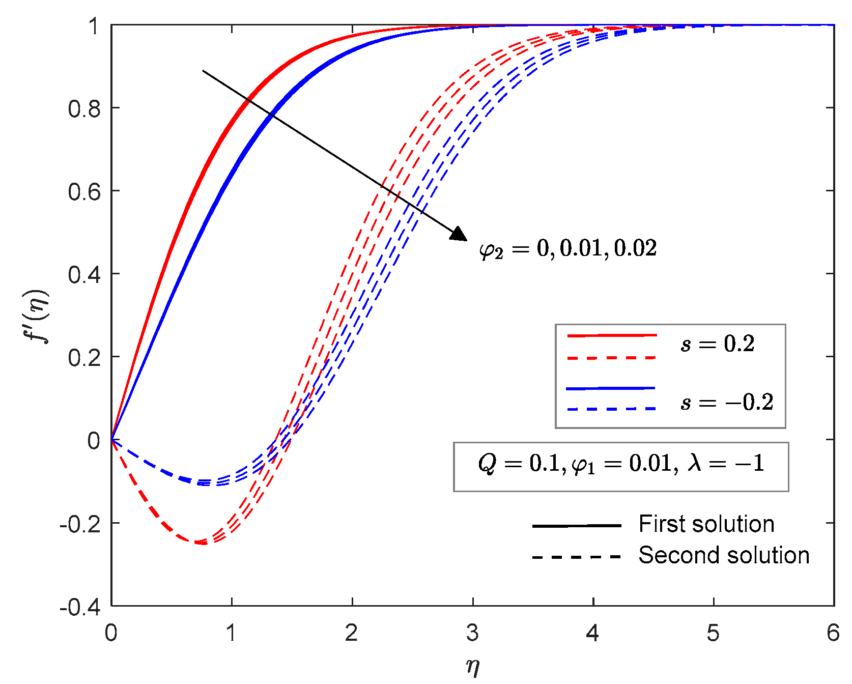
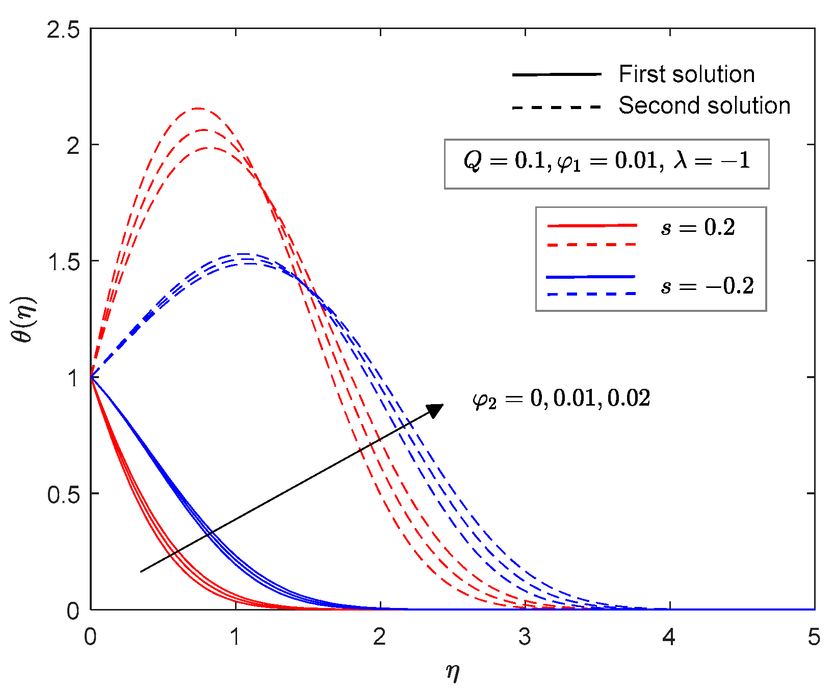
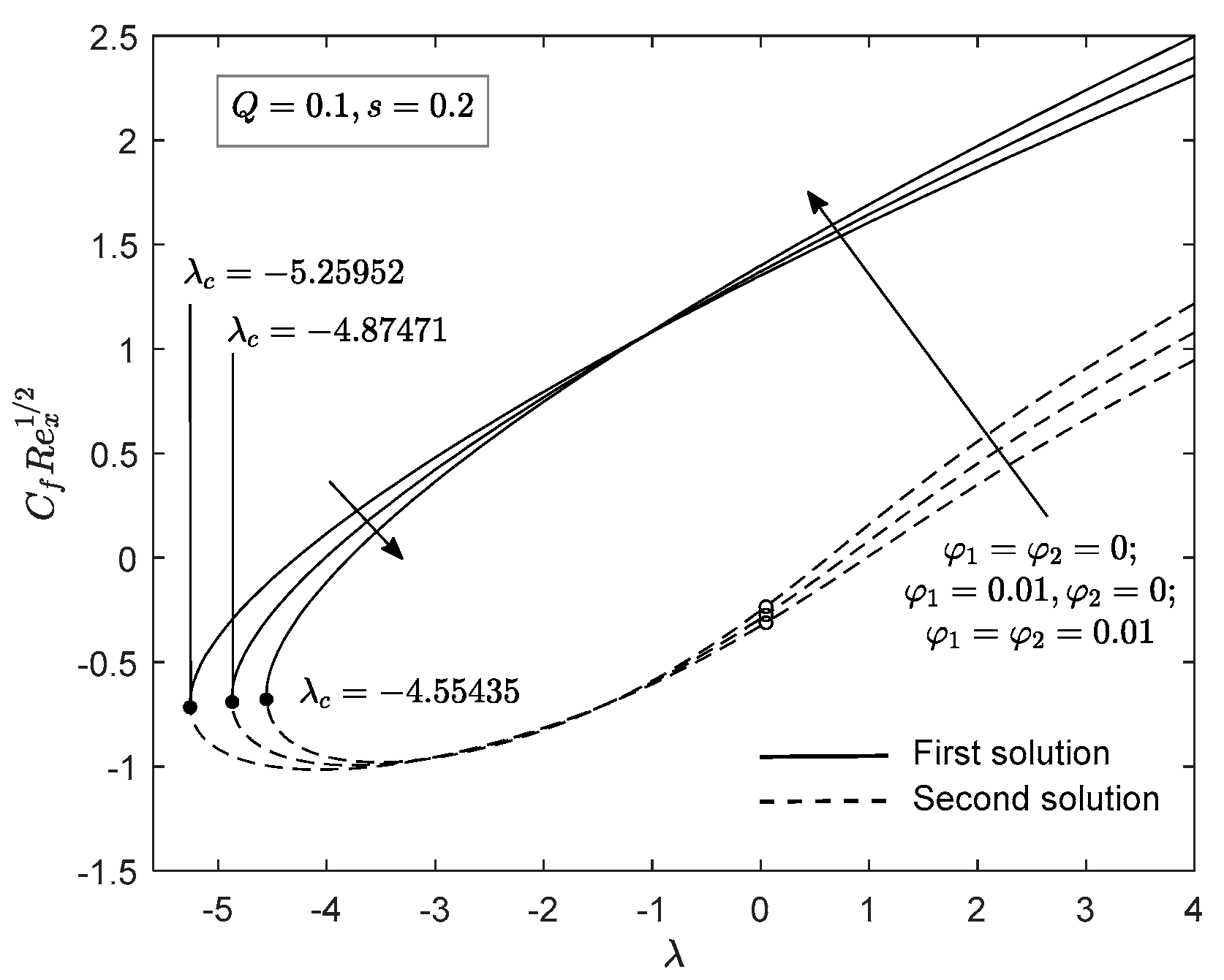
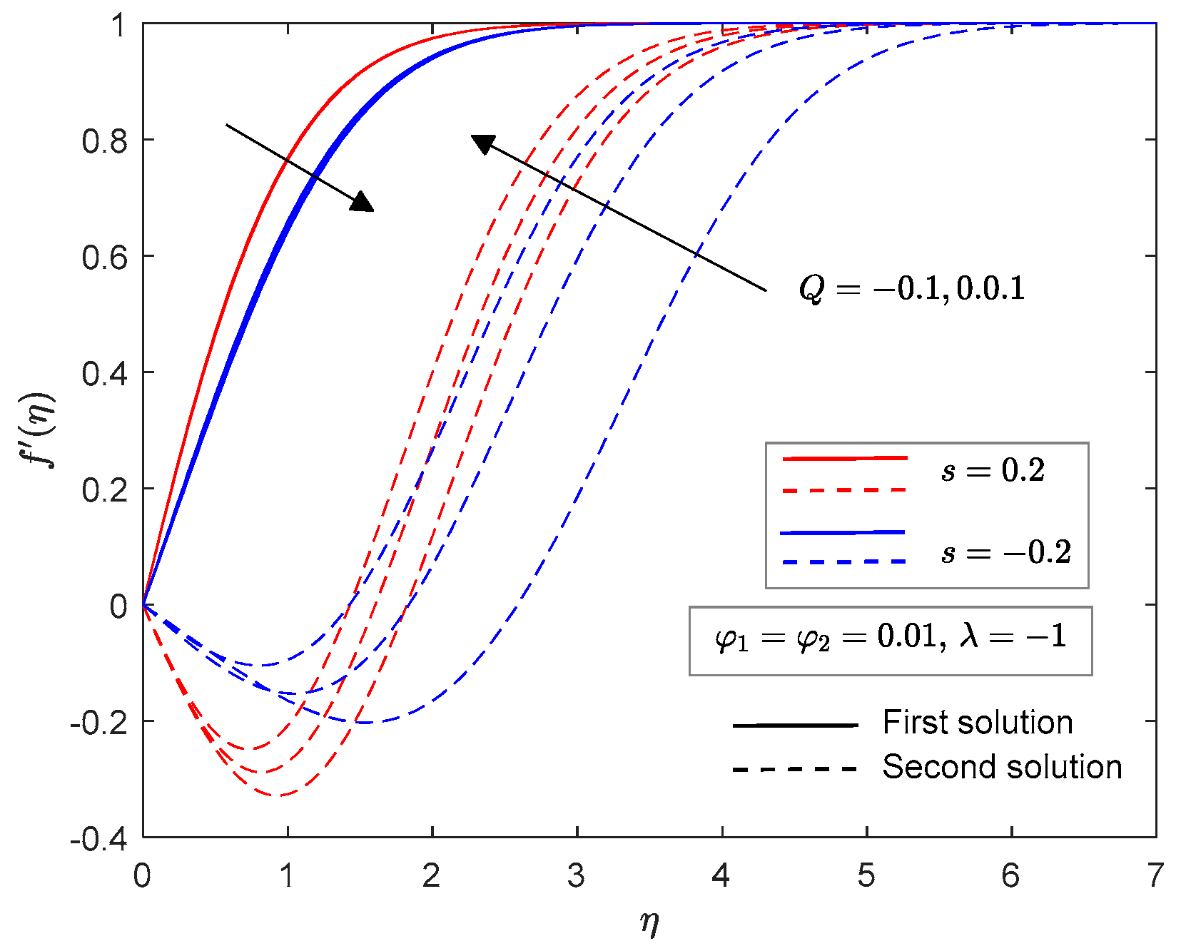
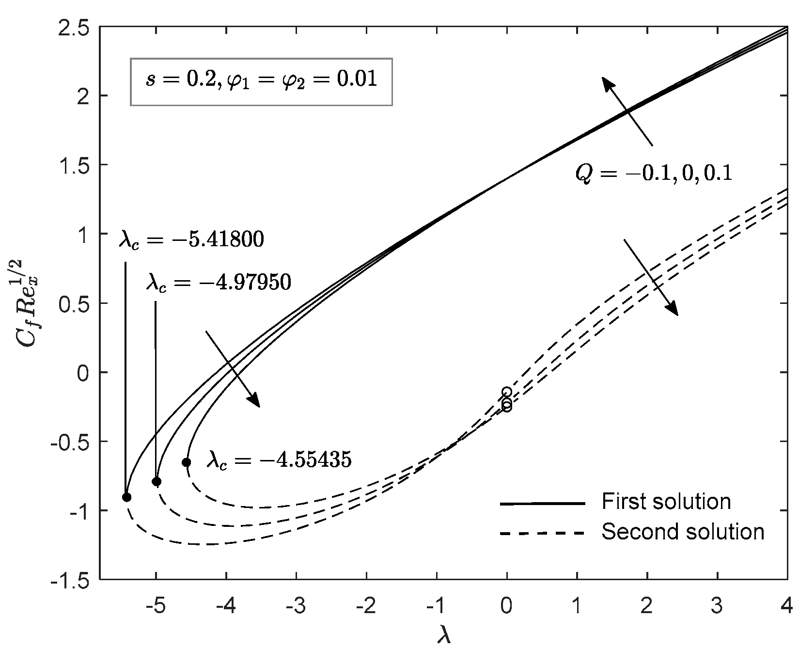
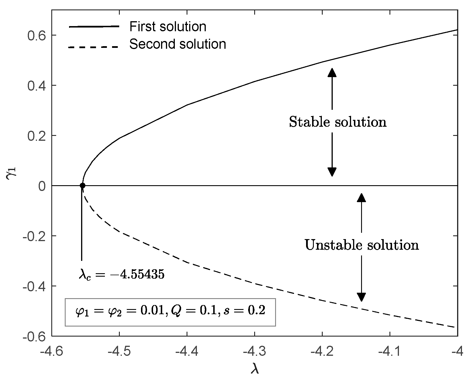
  • Two numerical solutions are discoverable for assisting buoyancy flow parameter ( 0 < λ 4 ) and opposing buoyancy flow parameter ( λ c < λ < 0 ) .
  • The stability analysis demonstrates that the first solution is stable whilst the second solution is not.
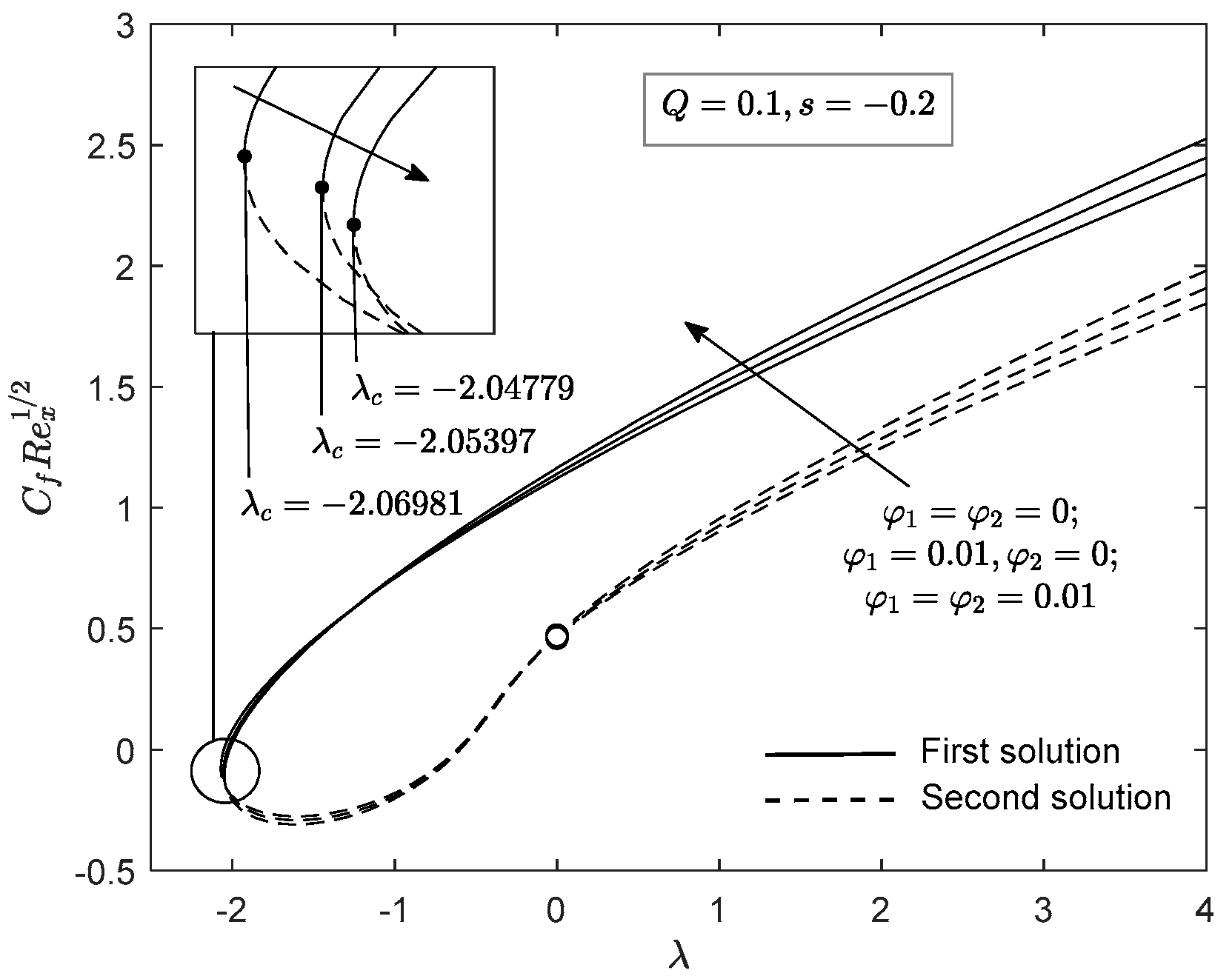
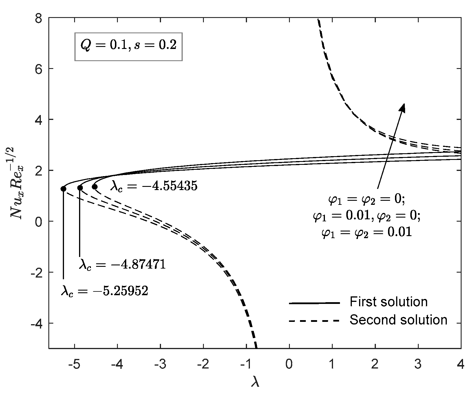
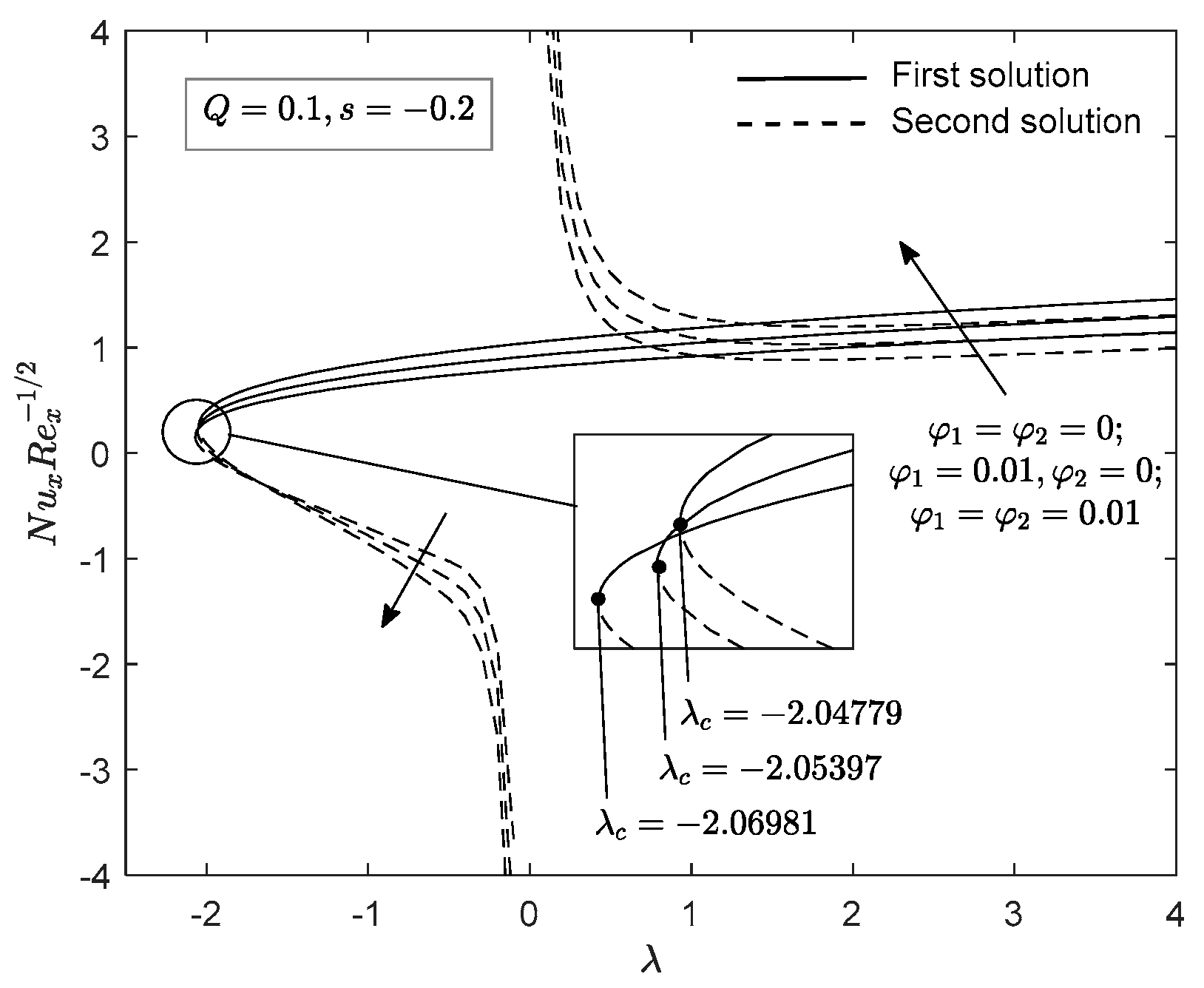
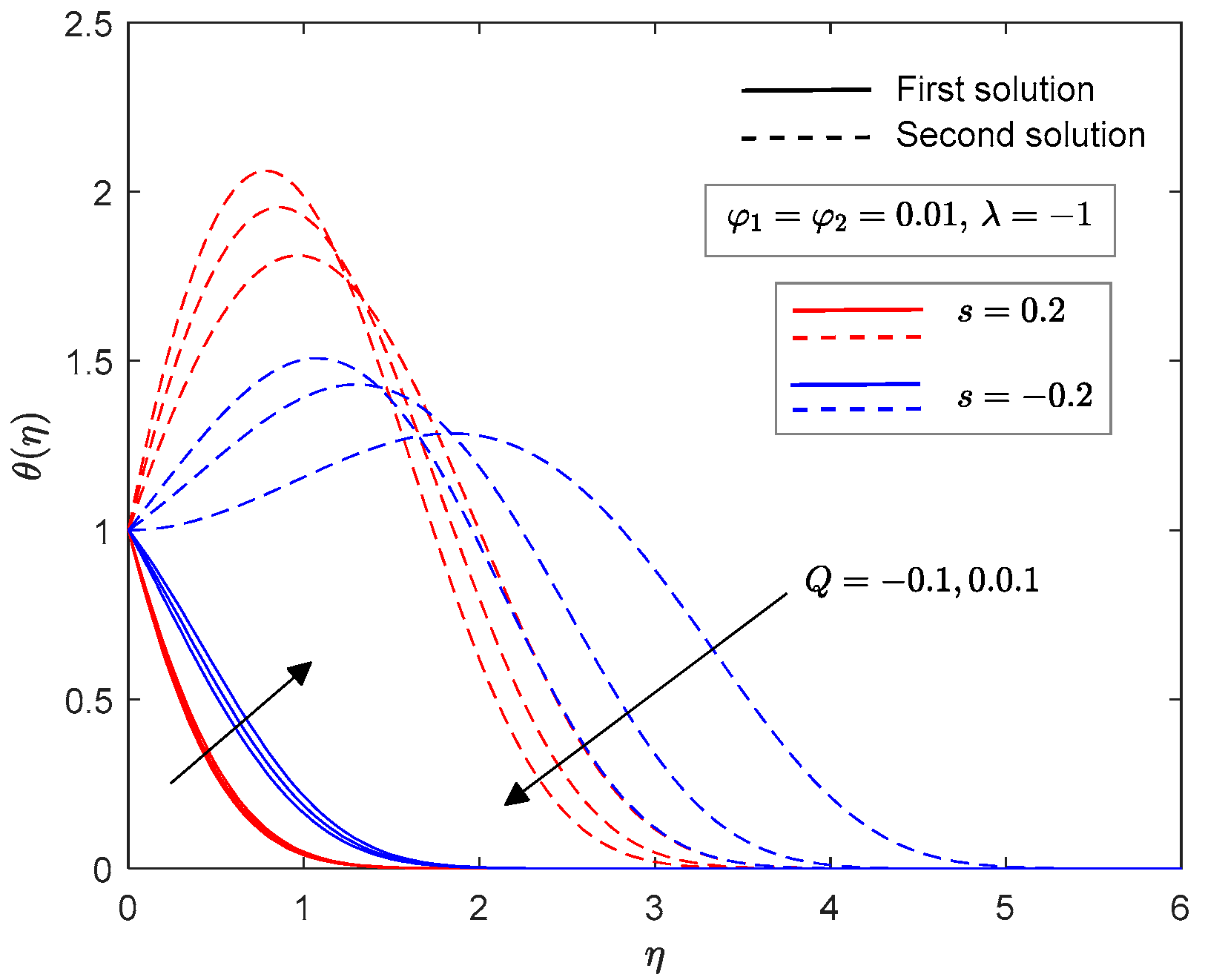
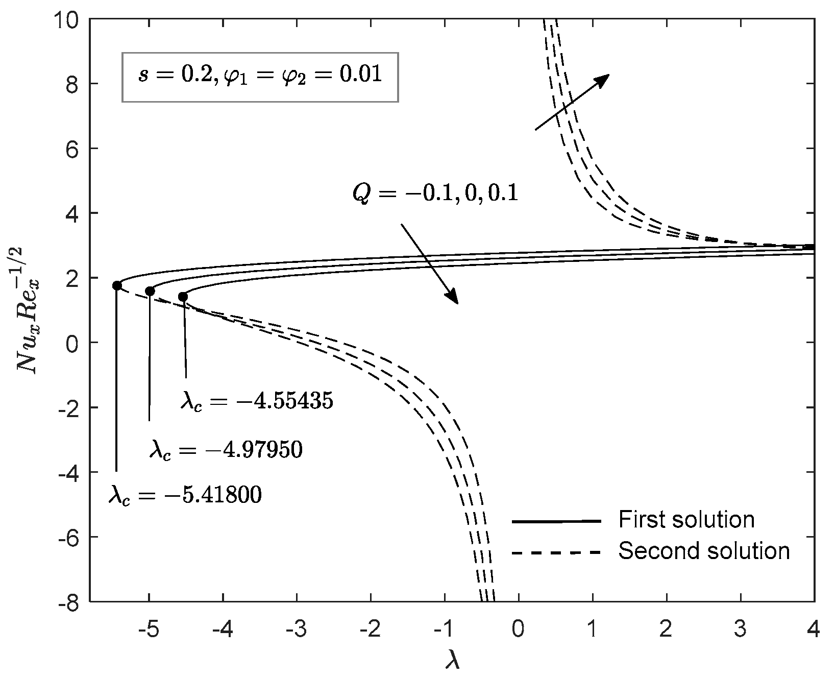
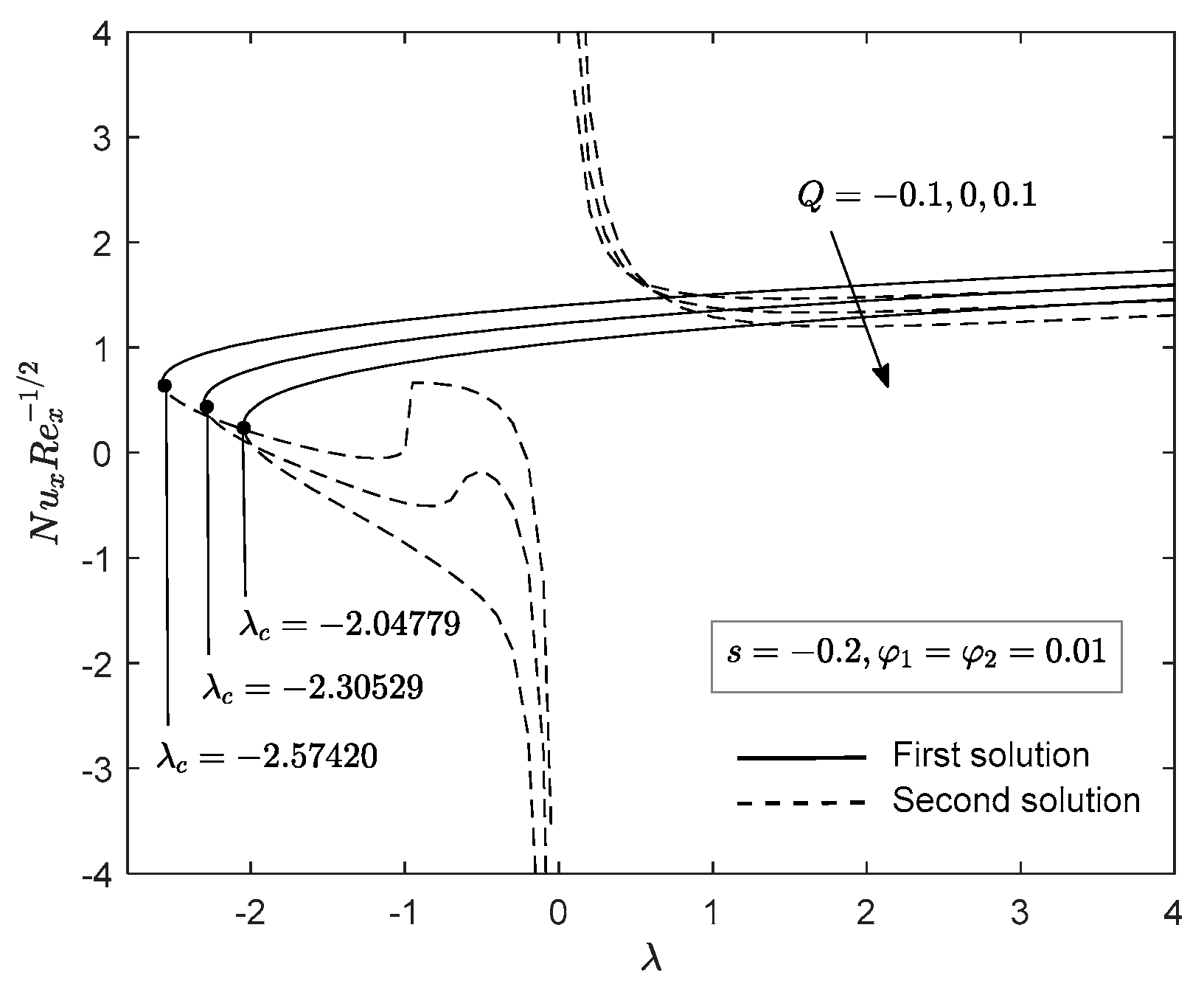
  • The domains of the similarity solutions decrease with the use of SWCNT–MWCNT/water hybrid nanofluid, injection effect, and heat generation. Therefore, it fastens the boundary layer separation. However, suction effect and heat absorption parameter delay the boundary layer separation.
  • The energy transport rate and skin friction coefficient of SWCNT–MWCNT/water hybrid nanofluid is more advanced than MWCNT/water nanofluid and ordinary fluid.
  • Heat absorption enhances the rate of heat transfer while heat generation decreases it.
  • The magnitude of local Nusselt number and skin friction coefficient are higher for assisting buoyancy flow than the opposing buoyancy flow case.
  • The heat-transfer rate is elevated in the presence of suction effect compared to the presence of injection effect.

Author Contributions

Conceptualization, N.B. and I.P.; methodology, formal analysis and writing—original draft preparation, N.S.A.; validation, N.S.A., N.B. and I.P.; writing—review and editing, supervision, N.B. and I.P.; funding acquisition, N.B. All authors have read and agreed to the published version of the manuscript.

Funding

This research was supported by the Fundamental Research Grant Scheme (FRGS) under Ministry of Higher Education with project number FRGS/1/2018/STG06/UPM/02/4.

Data Availability Statement

Not applicable.

Acknowledgments

The authors would like to express their gratitude to the anonymous reviewers for their valuable comments and suggestions for a betterment of this paper.

Conflicts of Interest

The authors declare no conflict of interest.

References

  1. Choi, S.U.; Eastman, J.A. Enhancing Thermal Conductivity of Fluids with Nanoparticles; Argonne National Lab.: Lemont, IL, USA, 1995. [Google Scholar]
  2. Bovand, M.; Rashidi, S.; Ahmadi, G.; Esfahani, J.A. Effects of trap and reflect particle boundary conditions on particle transport and convective heat transfer for duct flow-A two-way coupling of Eulerian-Lagrangian model. Appl. Therm. Eng. 2016, 108, 368–377. [Google Scholar] [CrossRef]
  3. Guthrie, D.G.; Torabi, M.; Karimi, N. Combined heat and mass transfer analyses in catalytic microreactors partially filled with porous material-The influences of nanofluid and different porous-fluid interface models. Int. J. Therm. Sci. 2019, 140, 96–113. [Google Scholar] [CrossRef] [Green Version]
  4. Suresh, S.; Venkitaraj, K.P.; Selvakumar, P.; Chandrasekar, M. Synthesis of Al2O3–Cu/water hybrid nanofluids using two step method and its thermo physical properties. Colloids Surf. A Physicochem. Eng. Asp. 2011, 388, 41–48. [Google Scholar] [CrossRef]
  5. Takabi, B.; Salehi, S. Augmentation of the heat transfer performance of a sinusoidal corrugated enclosure by employing hybrid nanofluid. Adv. Mech. Eng. 2014, 6, 147059. [Google Scholar] [CrossRef]
  6. Devi, S.A.; Devi, S.S.U. Numerical investigation of hydromagnetic hybrid Cu–Al2O3/water nanofluid flow over a permeable stretching sheet with suction. Int. J. Nonlinear Sci. Numer. Simul. 2016, 17, 249–257. [Google Scholar] [CrossRef]
  7. Ghadikolaei, S.S.; Hosseinzadeh, K.; Hatami, M.; Ganji, D.D. MHD boundary layer analysis for micropolar dusty fluid containing Hybrid nanoparticles (Cu-Al2O3) over a porous medium. J. Mol. Liq. 2018, 268, 813–823. [Google Scholar] [CrossRef]
  8. Anuar, N.S.; Bachok, N.; Pop, I. Influence of buoyancy force on Ag-MgO/water hybrid nanofluid flow in an inclined permeable stretching/shrinking sheet. Int. Commun. Heat Mass Transf. 2021, 123, 105236. [Google Scholar] [CrossRef]
  9. Ghadikolaei, S.S.; Hosseinzadeh, K.; Ganji, D.D.; Hatami, M. Fe3O4–(CH2OH)2 nanofluid analysis in a porous medium under MHD radiative boundary layer and dusty fluid. J. Mol. Liq. 2018, 258, 172–185. [Google Scholar] [CrossRef]
  10. Kumar, K.G.; Hani, E.H.B.; Assad, M.E.H.; Rahimi-Gorji, M.; Nadeem, S. A novel approach for investigation of heat transfer enhancement with ferromagnetic hybrid nanofluid by considering solar radiation. Microsyst. Technol. 2021, 27, 97–104. [Google Scholar] [CrossRef]
  11. Abbas, N.; Nadeem, S.; Saleem, A.; Malik, M.Y.; Issakhov, A.; Alharbi, F.M. Models base study of inclined MHD of hybrid nanofluid flow over nonlinear stretching cylinder. Chin. J. Phys. 2021, 69, 109–117. [Google Scholar] [CrossRef]
  12. Riasat, S.; Ramzan, M.; Sun, Y.L.; Malik, M.Y.; Chinram, R. Comparative analysis of Yamada-Ota and Xue models for hybrid nanofluid flow amid two concentric spinning disks with variable thermophysical characteristics. Case Stud. Therm. Eng. 2021, 26, 101039. [Google Scholar] [CrossRef]
  13. Iijima, S. Helical microtubules of graphitic carbon. Nature 1991, 354, 56–58. [Google Scholar] [CrossRef]
  14. Harrison, B.S.; Atala, A. Carbon nanotube applications for tissue engineering. Biomaterials 2007, 28, 344–353. [Google Scholar] [CrossRef]
  15. Raphey, V.R.; Henna, T.K.; Nivitha, K.P.; Mufeedha, P.; Sabu, C.; Pramod, K. Advanced biomedical applications of carbon nanotube. Mater. Sci. Eng. C 2019, 100, 616–630. [Google Scholar] [CrossRef] [PubMed]
  16. Jame, S.A.; Zhou, Z. Electrochemical carbon nanotube filters for water and wastewater treatment. Nanotechnol. Rev. 2016, 5, 41–50. [Google Scholar] [CrossRef]
  17. Yin, Z.; Cui, C.; Chen, H.; Yu, X.; Qian, W. The Application of Carbon Nanotube/Graphene-Based Nanomaterials in Wastewater Treatment. Small 2020, 16, 1902301. [Google Scholar] [CrossRef] [PubMed]
  18. Peng, L.M.; Zhang, Z.; Wang, S. Carbon nanotube electronics: Recent advances. Mater. Today 2014, 17, 433–442. [Google Scholar] [CrossRef]
  19. Zhao, J.; Shen, L.; Liu, F.; Zhao, P.; Huang, Q.; Han, H.; Peng, L.; Liang, X. Quality metrology of carbon nanotube thin films and its application for carbon nanotube-based electronics. Nano Res. 2020, 13, 1749–1755. [Google Scholar] [CrossRef]
  20. Nadeem, S.; Saleem, S. Unsteady mixed convection flow of nanofluid on a rotating cone with magnetic field. Appl. Nanosci. 2014, 4, 405–414. [Google Scholar] [CrossRef] [Green Version]
  21. Ishak, A.; Nazar, R.; Pop, I. Dual solutions in mixed convection boundary-layer flow with suction or injection. IMA J. Appl. Math. 2007, 72, 451–463. [Google Scholar] [CrossRef]
  22. Ishak, A.; Nazar, R.; Bachok, N.; Pop, I. MHD mixed convection flow near the stagnation-point on a vertical permeable surface. Phys. A Stat. Mech. Appl. 2010, 389, 40–46. [Google Scholar] [CrossRef]
  23. Tamim, H.; Dinarvand, S.; Hosseini, R.; Pop, I. MHD mixed convection stagnation-point flow of a nanofluid over a vertical permeable surface: A comprehensive report of dual solutions. Heat Mass Transf. 2014, 50, 639–650. [Google Scholar] [CrossRef]
  24. Rostami, M.N.; Dinarvand, S.; Pop, I. Dual solutions for mixed convective stagnation-point flow of an aqueous silica–alumina hybrid nanofluid. Chin. J. Phys. 2018, 56, 2465–2478. [Google Scholar] [CrossRef]
  25. Ghalambaz, M.; Roşca, N.C.; Roşca, A.V.; Pop, I. Mixed convection and stability analysis of stagnation-point boundary layer flow and heat transfer of hybrid nanofluids over a vertical plate. Int. J. Numer. Methods Heat Fluid Flow 2019, 30, 3737–3754. [Google Scholar] [CrossRef]
  26. Gireesha, B.J.; Mahanthesh, B.; Shivakumara, I.S.; Eshwarappa, K.M. Melting heat transfer in boundary layer stagnation-point flow of nanofluid toward a stretching sheet with induced magnetic field. Eng. Sci. Technol. Int. J. 2016, 19, 313–321. [Google Scholar] [CrossRef] [Green Version]
  27. Kumar, D.; Singh, A.K.; Kumar, D. Influence of heat source/sink on MHD flow between vertical alternate conducting walls with Hall effect. Phys. A Stat. Mech. Appl. 2020, 544, 123562. [Google Scholar] [CrossRef]
  28. Bhattacharyya, K. Effects of radiation and heat source/sink on unsteady MHD boundary layer flow and heat transfer over a shrinking sheet with suction/injection. Front. Chem. Sci. Eng. 2011, 5, 376–384. [Google Scholar] [CrossRef]
  29. Ahmed, S.E.; Hussein, A.K.; Mohammed, H.A.; Sivasankaran, S. Boundary layer flow and heat transfer due to permeable stretching tube in the presence of heat source/sink utilizing nanofluids. Appl. Math. Comput. 2014, 238, 149–162. [Google Scholar] [CrossRef]
  30. Makinde, O.D.; Mabood, F.; Ibrahim, M.S. Chemically reacting on MHD boundary-layer flow of nanofluids over a non-linear stretching sheet with heat source/sink and thermal radiation. Therm. Sci. 2018, 22, 495–506. [Google Scholar] [CrossRef]
  31. Agrawal, P.; Dadheech, P.K.; Jat, R.N.; Bohra, M.; Nisar, K.S.; Khan, I. Lie similarity analysis of MHD flow past a stretching surface embedded in porous medium along with imposed heat source/sink and variable viscosity. J. Mater. Res. Technol. 2020, 9, 10045–10053. [Google Scholar] [CrossRef]
  32. Anwar, T.; Kumam, P.; Shah, Z.; Watthayu, W.; Thounthong, P. Unsteady radiative natural convective MHD nanofluid flow past a porous moving vertical plate with heat source/sink. Molecules 2020, 25, 854. [Google Scholar] [CrossRef] [PubMed] [Green Version]
  33. Reddy, N.N.; Rao, V.S.; Reddy, B.R. Chemical reaction impact on MHD natural convection flow through porous medium past an exponentially stretching sheet in presence of heat source/sink and viscous dissipation. Case Stud. Therm. Eng. 2021, 25, 100879. [Google Scholar] [CrossRef]
  34. Merkin, J.H. On dual solutions occurring in mixed convection in a porous medium. J. Eng. Math. 1986, 20, 171–179. [Google Scholar] [CrossRef]
  35. Anuar, N.S.; Bachok, N. Double solutions and stability analysis of micropolar hybrid nanofluid with thermal radiation impact on unsteady stagnation point flow. Mathematics 2021, 9, 276. [Google Scholar] [CrossRef]
  36. Arani, A.A.A.; Aberoumand, H. Stagnation-point flow of Ag-CuO/water hybrid nanofluids over a permeable stretching/shrinking sheet with temporal stability analysis. Powder Technol. 2021, 380, 152–163. [Google Scholar] [CrossRef]
  37. Wahid, N.S.; Arifin, N.M.; Khashi’ie, N.S.; Pop, I. Hybrid Nanofluid Slip Flow over an Exponentially Stretching/Shrinking Permeable Sheet with Heat Generation. Mathematics 2021, 9, 30. [Google Scholar] [CrossRef]
  38. Khan, U.; Waini, I.; Ishak, A.; Pop, I. Unsteady hybrid nanofluid flow over a radially permeable shrinking/stretching surface. J. Mol. Liq. 2021, 331, 115752. [Google Scholar] [CrossRef]
  39. Aman, S.; Khan, I.; Ismail, Z.; Salleh, M.Z.; Al-Mdallal, Q.M. Heat transfer enhancement in free convection flow of CNTs Maxwell nanofluids with four different types of molecular liquids. Sci. Rep. 2017, 7, 1–13. [Google Scholar] [CrossRef] [Green Version]
  40. Weidman, P.D.; Kubitschek, D.G.; Davis, A.M.J. The effect of transpiration on self-similar boundary layer flow over moving surfaces. Int. J. Eng. Sci. 2006, 44, 730–737. [Google Scholar] [CrossRef]
  41. Harris, S.D.; Ingham, D.B.; Pop, I. Mixed convection boundary-layer flow near the stagnation point on a vertical surface in a porous medium: Brinkman model with slip. Transp. Porous Media 2009, 77, 267–285. [Google Scholar] [CrossRef]
  42. Ramachandran, N.; Chen, T.S.; Armaly, B.F. Mixed convection in stagnation flows adjacent to vertical surfaces. J. Heat Transf. 1988, 110, 373–377. [Google Scholar] [CrossRef]
Figure 1. Physical model.
Mathematics 09 02925 g001
Figure 2. Impact of SWCNT nanoparticle on f ( η ) .
Mathematics 09 02925 g002
Figure 3. Influence of SWCNT nanoparticle on θ ( η ) .
Mathematics 09 02925 g003
Figure 4. C f Re x 1 / 2 for selected value of the nanoparticle when s = 0.2 .
Mathematics 09 02925 g004
Figure 5. C f Re x 1 / 2 for some value of the nanoparticle when s = 0.2 .
Mathematics 09 02925 g005
Figure 6. N u x Re x 1 / 2 for different nanoparticles when s = 0.2 .
Mathematics 09 02925 g006
Figure 7. N u x Re x 1 / 2 for selected nanoparticles when s = 0.2 .
Mathematics 09 02925 g007
Figure 8. Influence of heat source/sink on f ( η ) .
Mathematics 09 02925 g008
Figure 9. Impact of heat source/sink on θ ( η ) .
Mathematics 09 02925 g009
Figure 10. C f Re x 1 / 2 for different heat generation/absorption when s = 0.2 .
Mathematics 09 02925 g010
Figure 11. C f Re x 1 / 2 for different heat generation/absorption when s = 0.2 .
Mathematics 09 02925 g011
Figure 12. N u x Re x 1 / 2 for selected value of heat generation/absorption when s = 0.2 .
Mathematics 09 02925 g012
Figure 13. N u x Re x 1 / 2 for selected value of heat generation/absorption when s = 0.2 .
Mathematics 09 02925 g013
Figure 14. Smallest eigenvalues γ 1 against λ .
Mathematics 09 02925 g014
Table 1. Thermo-physical characteristic of hybrid nanofluid.
PropertiesHybrid Nanofluid
Dynamic viscosity μ h c n t = μ f ( 1 φ ) 2.5
Heat capacity ( ρ C p ) h c n t = ( 1 φ ) ( ρ C p ) f + φ ( ρ C p ) h p   where ( ρ C p ) h p = φ 1 ( ρ C p ) 1 + φ 2 ( ρ C p ) 2 φ
Thermal expansion β h c n t = ( 1 φ ) β f + φ β h p   where   β h p = φ 1 β 1 + φ 2 β 2 φ
Density ρ h c n t = ( 1 φ ) ρ f + φ ρ h p   where   ρ h p = φ 1 ρ 1 + φ 2 ρ 2 φ
Thermal conductivity k h c n t k f = 1 φ + 2 φ k h p k h p k f ln ( k h p + k f 2 k f ) 1 φ + 2 φ k f k h p k f ln ( k h p + k f 2 k f )   where   k h p = φ 1 k 1 + φ 2 k 2 φ
Table 2. Properties of base fluid and carbon nanotube.
Physical Properties
k ( W · m 1 · K 1 ) C p ( J · k g 1 · K 1 ) ρ ( k g · m 3 ) β ( × 10 5 k 1 )
Base fluid:
water0.6134179997.121
Carbon nanotube:
SWCNT6600425260027
MWCNT3000796160044
Table 3. Values of f ( 0 ) when φ 1 = φ 2 = 0 , s = 0 , Q = 0 .
Pr Assisting   Flow   ( λ   =   1 ) Opposing   Flow   ( λ   =   1 )
Ref. [42]Ref. [25]Present ResultRef. [42]Ref. [25]Present Result
0.71.70631.70631.706323
[1.238720]
0.69170.69170.691661
[−0.28505]
7.01.51791.51791.517913
[0.582401]
0.92350.92350.923481
[−0.375337]
201.44851.44851.4484831.00311.00311.003108
“[ ]” Second solution.
Table 4. Comparisons of θ ( 0 ) when φ 1 = φ 2 = 0 , s = 0 , Q = 0 .
Pr Assisting   Flow   ( λ   =   1 ) Opposing   Flow   ( λ   =   1 )
Ref. [42]Ref. [25]Present ResultRef. [42]Ref. [25]Present Result
0.70.76410.76410.764063
[1.022633]
0.63320.63320.633247
[−0.222165]
7.0−1.7224−1.72241.722382
[2.219194]
1.54601.54601.546032
[−1.285559]
202.45762.45762.4575902.26832.26832.268272
“[ ]” Second solution.
Publisher’s Note: MDPI stays neutral with regard to jurisdictional claims in published maps and institutional affiliations.

