1. Introduction
With the development of science and technology, clean energy has become an integral part of society. Wind energy is a kind of renewable clean energy, and wind power generation is an important part of non-fossil energy power generation. Furthermore, wind power generation plays a key role in reducing the use of fossil energy and alleviating environmental pollution.
The gear transmission system, which is in the gearbox of the wind power generation, has an important impact on the stability of the system, and many scholars have carried out modeling analysis on it [
1,
2]. Based on a 1.5 MW wind turbine, Chen et al. [
3] established a planetary gear system considering random wind speed excitation, and they studied the change of system response under the random component of comprehensive error. Zhao et al. [
4] established a nonlinear dynamic model of the two-stage planetary gear and one-stage parallel axial gear transmission. Sun et al. [
5] established an 8-DOF dynamic differential equation, and the dynamic responses caused by progressive tooth wear was studied. Wang et al. [
6] transformed the semi-custom system with a rigid displacement model into a custom system. Then, the dynamic characteristics of a one-stage planetary gear transmission system and two-stage parallel axial gear transmission system were analyzed. Xu et al. [
7] divided the gearbox of the wind power system into a transmission subsystem and an ontology subsystem. Then, the dynamic characteristics of the system were analyzed, and experiments were carried out.
Most of the above literature was calculated by the numerical method; however, the analysis methods of gear systems are becoming more and more diversified. Based on the parametric model order reduction (PMOR) scheme and the Hertz theory, Niccolò et al. [
8] proposed a combined analytic–numerical contact model to solve the contact problem of flexible multi-body gears. According to the dynamic modeling and signal processing method, Wu et al. [
9] proposed a gear crack fault feature analysis method. It included a local oscillatory-characteristic decomposition (LOD) method and an analytical–finite element gear contact model. Lin et al. [
10] established the semi-analytical contact model by combining the penalty element method and Lagrange multiplier method. Then, the dynamic contact analysis of a helical gear pair was carried out.
In the process of gear meshing, most of the energy consumed by friction is converted into heat. Then, that inevitably leads to increasing of the tooth surface temperature and influences the contact conditions as well as system stability. Based on the flash temperature theory and the Hertz contact theory, Gou et al. [
11] calculated the time-varying meshing stiffness considering the tooth surface contact temperature and analyzed the dynamic characteristics of the gear system under corresponding working conditions. Mao [
12] took the polymer composite gear as the research object and studied the flash temperature as well as heat distribution between teeth, which provided a new idea for the design of polymer composite gears. Su et al. [
13] analyzed the heat generation, as well as conduction in the process of the gear form grinding, and established the corresponding mathematical model. Pan et al. [
14] established a time-varying meshing stiffness model including the influence of tooth contact temperature, friction coefficient, and normal load. Then, it was substituted into the nonlinear dynamic model of a gear-bearing system with 10 degrees of freedom.
However, with increasing of the tooth surface temperature, it is easy to cause the tooth surface wear and scuffing, which will make the backlash change. Then, the nonlinearity of the gear system is enhanced, and the motion state of the system tends to be unstable. Wang [
15] combined the tooth surface wear with the changing of backlash. Then, it provided the vibration mechanism and the fault wear diagnosis method of the multi-stage gear transmission system. Li et al. [
16,
17] established a 9-DOF dynamic model of the gear-bearing system. Then, they studied the effects of backlash with fractal characteristics and backlash with tooth surface wear on the dynamic characteristics of the system.
Meanwhile, the tooth surface wear and scuffing also can change the meshing stiffness. Wang [
18] and Feng et al. [
19] both analyzed the gear-meshing stiffness under wear condition, but the methods were different. Wang et al. [
18] used the Weber–Banaschek method to calculate the wear stiffness and analyzed the effect of wear on the system. However, according to the Timoshinko beam theory, Feng et al. [
19] calculated the influence of wear on stiffness more accurately, which provided a technical path for the gear dynamic modeling considering tooth surface wear. Huangfu et al. [
20] established the wear prediction model and the gear dynamic model, comparing the results obtained with the finite element model. Then, the change of wear depth with speed is analyzed.
In this paper, the gear-bearing system in references [
14,
16] is taken as the research object. Although both references are based on the same gear-bearing system, the stiffness and backlash considered in the model are quite different. In reference [
14], the effects of tooth surface flash temperature and the backlash with fractal characteristics on the system response were analyzed, but the calculation of tooth surface wear was not involved. In reference [
16], the fractal theory and the Archard theory were used to calculate the tooth surface wear. Then, the influence of wear amount of different fractal dimensions on system response was studied. However, the wear amount of each period was regarded as the same, and the dynamic changing process of tooth surface wear was not considered.
Above all, the influence of dynamic wear, considering the initial tooth surface wear and tooth surface contact temperature, on the response of the gear-bearing system is studied. In
Section 2, the gear-bearing systems considering different backlash and meshing stiffness are introduced to calculate parameters (initial tooth surface wear, dynamic tooth surface wear, and tooth surface temperature). Then, dynamic characteristics of the gear-bearing system with the initial tooth surface wear are studied. In
Section 3, the meshing stiffness, considering tooth surface temperature, is established based on the flash temperature theory. Then, the meshing forces of gear bearing considering the backlash, which has fractal characteristics, are calculated. Furthermore, the influence of meshing force and friction coefficient on the tooth surface temperature and meshing stiffness is analyzed. In
Section 4, based on the tooth surface temperature model and the initial tooth surface wear, the dynamic wear model of the tooth surface is established. Furthermore, the effects of the tooth surface initial wear, the dynamic wear, the tooth contact temperature, and the damping ratio on the dynamic characteristics of the gear-bearing system are analyzed.
2. System Model
The gear-bearing system in references [
14,
16] is taken as the research object, and the model diagram is shown in
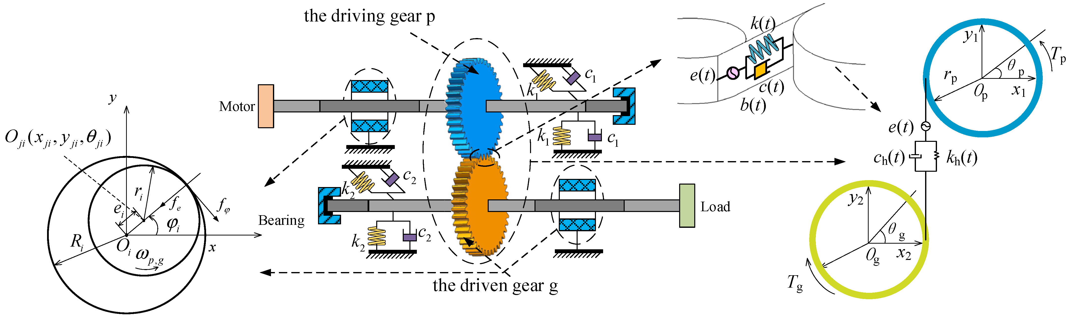
Figure 1. The meshing stiffness, considering the tooth surface flash temperature and the backlash with tooth surface wear, are calculated. Then, the dynamic wear model of a gear is constructed, and the interaction between the surface fractal dimension, temperature, and wear is analyzed.
In the model, the gear is an involute spur gear, and the bearing is a sliding bearing. Considering the time-varying meshing stiffness, backlash, tooth surface friction, comprehensive transmission error, nonlinear oil film force, and radial vibrations of the shaft and the torsional vibration of two gears, the coordinate system xiOiyi (i = 1 or 2) is established, in which O1 and O2 are the geometric centers of the two bearings, Oj1 and Oj2 are the centers of the two transmission shafts, and Op and Og are the geometric centers of the driving and driven gears, respectively.
To calculate parameters (initial tooth surface wear, dynamic tooth surface wear, and tooth surface temperature), the gear-bearing systems considering different backlash and meshing stiffness are defined. Then, the gear-bearing system considering backlash with fractal characteristics is called System I, through which the meshing force is calculated; the gear-bearing system considering backlash with initial tooth surface wear is called System II, through which the system response under a wear condition is analyzed; and the gear-bearing system considering the dynamic wear model is called System III.
In this paper, the backlash considering the initial tooth surface wear (
Section 4.1) is calculated, and it is substituted into the gear-bearing system (System II). We are using the parameters
μ = 0.3,
ki = 1,
ζh = 0.01,
ζ1 =
ζ2 =
ζp =
ζg = 0.01,
ep =
eg = 0.01,
e = 0.1,
Fm = 0.105,
Fa = 0.01, and
D = 1.5, and the system component parameters are shown in Tables 1–3 in reference [
16]. The Runge–Kutta method is used to calculate, and the dynamic equations are shown in Equation (8) in reference [
16]. The bifurcation diagram, the top Lyapunov exponent diagram, and the three-dimensional spectrum diagram are obtained, respectively, as shown in
Figure 2.
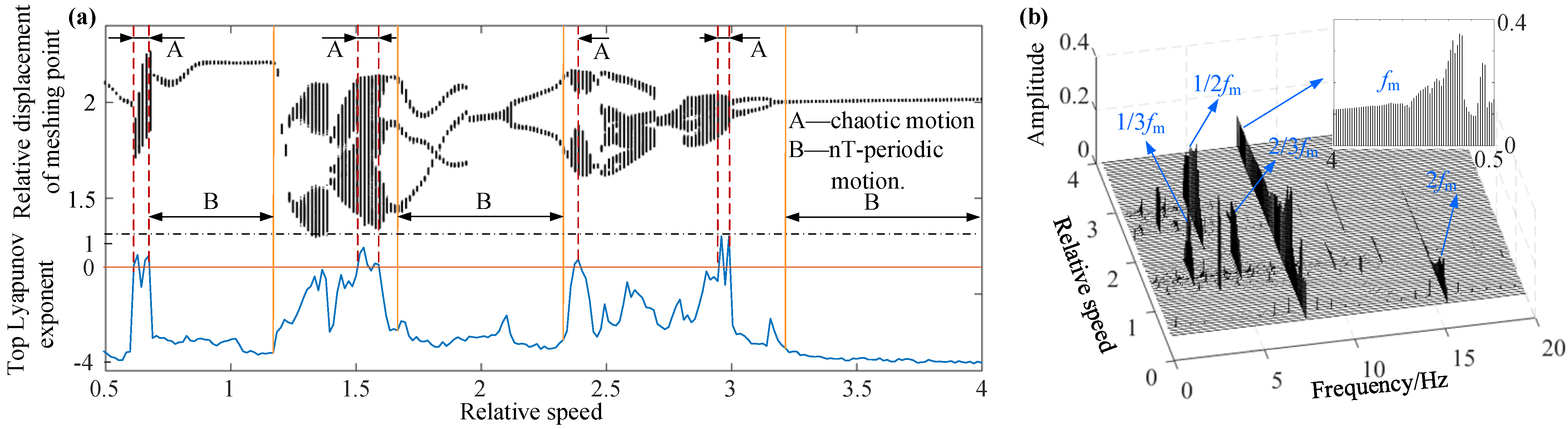
From
Figure 2a, it can be observed that the system has experienced a series of motion states, such as
nT-periodic, quasi-periodic, and chaotic in the process of the relative speed changing from 0.5 to 4. In
Figure 2a, region A represents the chaotic motion state and its corresponding top Lyapunov exponent is greater than zero; region B represents the
nT-periodic motion state and its corresponding top Lyapunov exponent is less than zero; other regions are quasi-periodic motion states between the chaotic and periodic motion state. In region A, there is a sudden change of the top Lyapunov exponent, and the system motion states have also changed correspondingly, which also indicates that the system is unstable in this speed range. At the same time, it can be observed from
Figure 2b that the system contains 1/3
fm, 1/2
fm, 2/3
fm,
fm, and 2
fm harmonic responses, which can prove that the system has rich nonlinear factors.
4. Dynamic Wear Model of the Tooth Surface
Tooth surface wear is a dynamic process and the contact temperature, as well as system excitation, have an important impact on it. At the same time, wear can also change the conditions of the tooth surface contact, which has an impact on the stiffness and tooth surface temperature. Furthermore, the tooth surface wear is generally calculated by Archard theory [
24], which is given by:
where
V is the wear volume of the material,
s is the relative sliding distance,
W is the positive pressure of the contact surface,
H is the hardness of the material, and
K is the wear coefficient.
The meshing process of the gear is discretized into the movement of each meshing point and the wear amount at different meshing point is calculated, which is shown by:
It can be observed that the calculation of the tooth surface wear mainly involves three parameters: wear coefficient
k, sliding distance s, and contact pressure
P. Then, the wear coefficient
k is 5 × 10
−16 m
2/N, the contact pressure is calculated by Equation (7), and the sliding distance is calculated by the equation in reference [
21], which is given by:
where
vp and
vg are the sliding speeds of the driving and driven gears, respectively, which are shown by Equation (3), and
aH is the half-width of the contact zone.
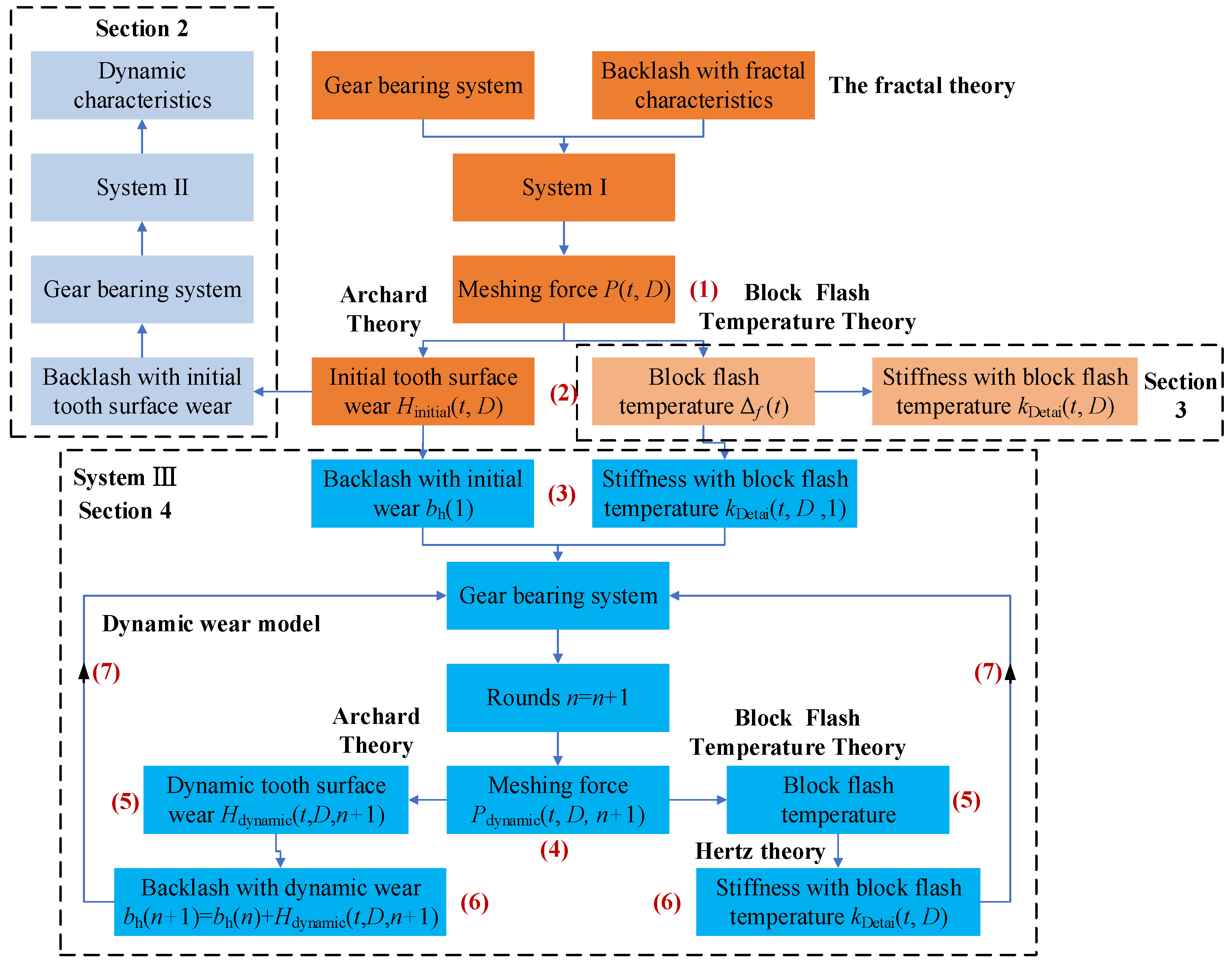
In order to analyze and calculate the dynamic wear model more accurately, a certain initial wear amount (
Hinitial) is adopted in the numerical calculation of the system. The calculation flow of dynamic wear is shown in
Figure 8. Then, the specific steps are as follows:
- (1)
The fractal theory is used to describe the backlash in order to represent the error caused by gear manufacturing and installation. Then, the meshing force P(t, D) is obtained through System I.
- (2)
Based on the Archard theory and flash temperature theory, the initial tooth surface wear and the flash temperature are calculated.
- (3)
The backlash bh(1) with initial wear and the stiffness kDetai (t, D, 1) with flash temperature in the first round are calculated, which represent the initial conditions of the gear system. Then, they are substituted into System III.
- (4)
According to System III, the dynamic meshing force Pdynamic(t, D, n + 1) can be obtained.
- (5)
The dynamic tooth surface wear Hdynamic(t, D, n + 1) and the flash temperature in the (n + 1)th round are calculated.
- (6)
The backlash bh(n + 1) in the (n + 1)th round is obtained by adding the dynamic wear Hdynamic(t, D, n+1) to the backlash bh(n) in the (n)th round. Then, the stiffness with flash temperature kDetai(t, D) in the (n + 1)th round is obtained based on the Hertz theory.
- (7)
The backlash bh(n + 1) and the stiffness with flash temperature kDetai(t, D) in the (n + 1)th round are substituted into System III. Then, go back to step 4 until the total time is reached.
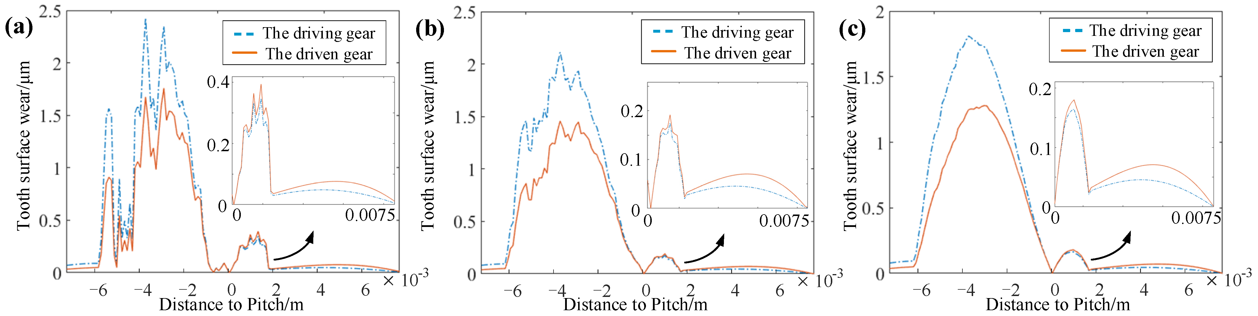
4.1. Calculation of Initial Wear
Based on System I, the meshing forces with different fractal dimensions
D are calculated. Then, based on Equation (12), the tooth surface wear Δ
h in one period
T is obtained. It is assumed that the amount of wear per round is the same and the tooth surface wear of 10
6 rounds is calculated, that is, Δ
h × 10
6. The accumulated wear of the tooth surface is shown in
Figure 9; furthermore, it is called the initial tooth surface wear (
Hinitial) in this paper. From
Figure 9, it can be observed that with increase of
D, the amplitude and the fluctuation of the tooth surface wear decrease.
4.2. Influence of Dynamic Wear on the System Response
Based on backlash considering the initial tooth surface wear (
Hinitial) and the meshing stiffness considering the tooth surface flash temperature, the gear-bearing system considering the dynamic wear model (System III) is calculated. Taking the parameters as
μ = 0.3,
ki = 1,
ζh = 0.01,
ζ1 =
ζ2 =
ζp =
ζg = 0.01,
μm = 0.06,
ep =
eg = 0.01,
e = 0.1,
Fm = 0.105,
Fa = 0.01, and
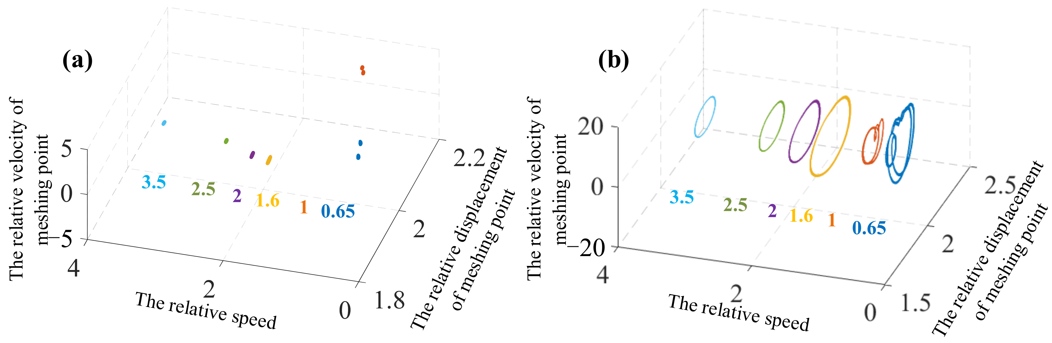
ω = 1.5, the dynamic characteristics of the gear system with 100 rounds are calculated and simulated. Then, the phase diagrams, the Poincare section diagrams, and the time domain diagrams of the system are obtained, as shown in
Figure 10,
Figure 11 and
Figure 12.
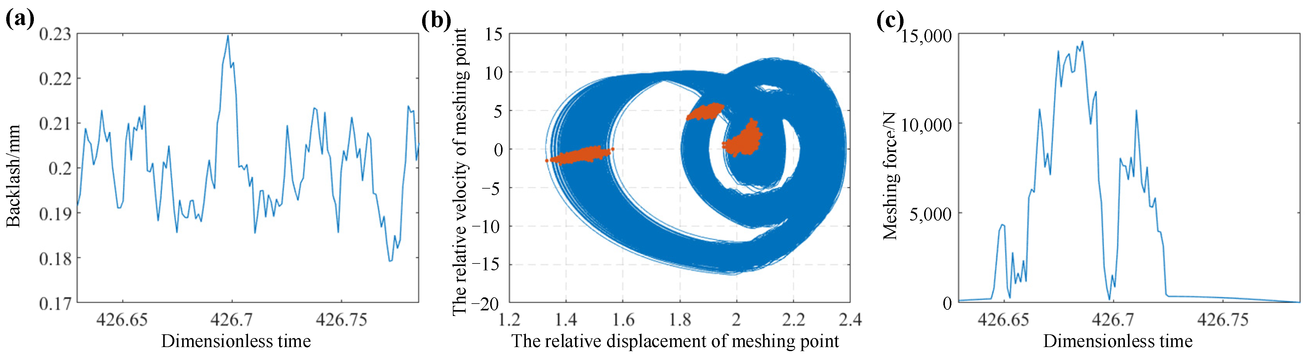
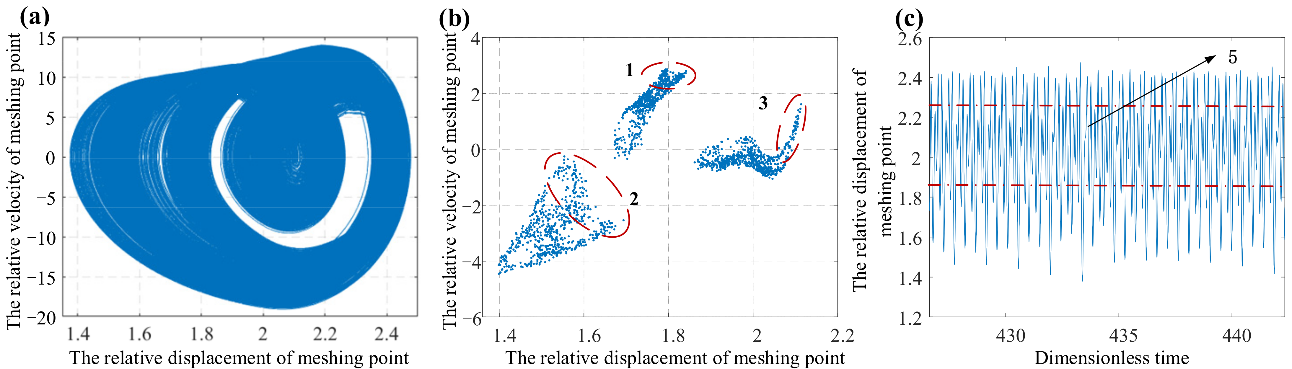
It can be observed that due to the different initial tooth surface wear (
Hinitial), the system responses are slightly different after the same numbers of periods. When the fractal dimension
D is 1.43, there are less blanks in the phase diagram (
Figure 10a), which indicates that the phase trajectories of the system are widely distributed in the space; regions 1, 2, and 3 in the Poincare section diagram (
Figure 10b) are dispersive, and the regularity of motion is weak; at the same time, in
Figure 10c, the displacement in region 5 (the time-domain diagram) fluctuates greatly, and all the above phenomena indicate that the system is unstable. When the fractal dimension
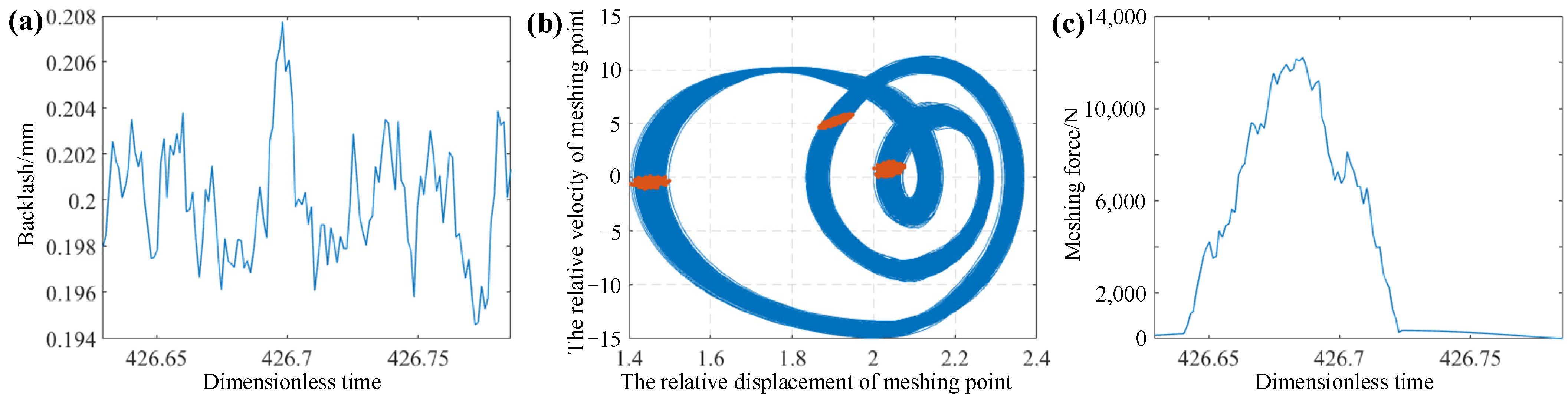
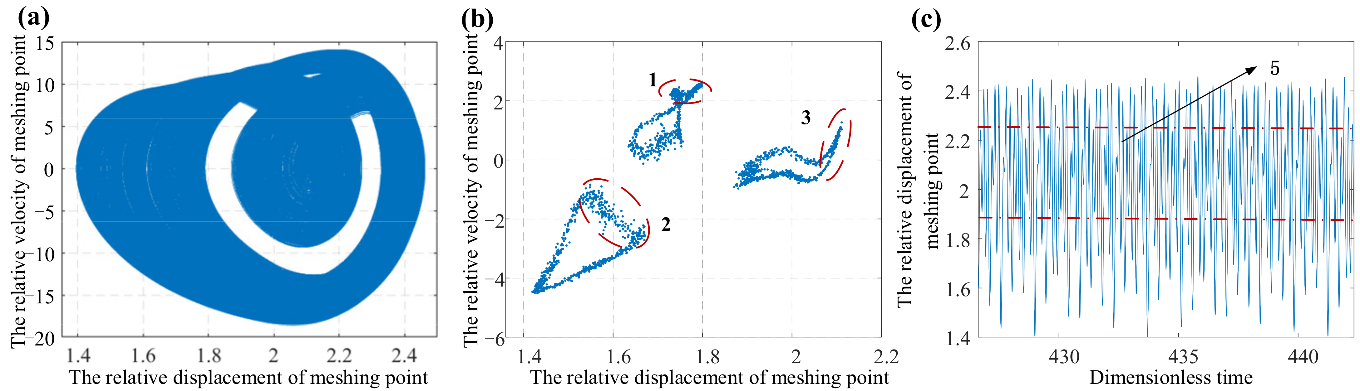
D is 1.5, the blank area in
Figure 11a becomes larger, which indicates that the concentration region of phase trajectories is smaller than that of
D = 1.43; this phenomenon can also be obtained from the Poincare section diagram (
Figure 11b), where regions 1, 2, and 3 begin to contract; at the same time, the displacement of region 5 in
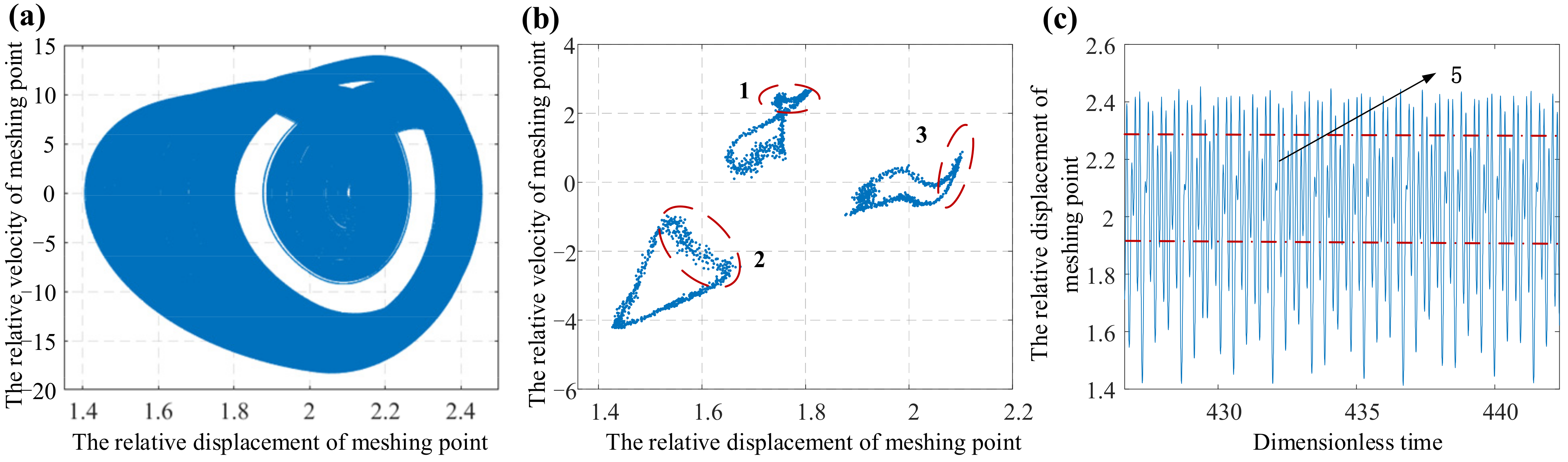
Figure 11c also shows a periodic change with small fluctuation, which proves that the system tends to be stable. As the fractal dimension continues to increase, the initial wear amount is low when the fractal dimension
D is 1.6. The difference between
Figure 11a and
Figure 12a is not obvious, the set of points in
Figure 12b continues to contract, and the changing of displacement in
Figure 12c basically conforms to periodic motion. Furthermore, all these indicate that the motion state of the system is more stable.
In conclusion, the fractal characteristics of backlash represent the uncertainty and amplitude. That is, the amplitude and the uncertainty of backlash decrease with the increase of the fractal dimension D. As a result, the initial tooth surface wear (Hinitial) becomes smaller. Then, the system response (system III) becomes stable gradually. Thus, the stable backlash can slow down the tooth surface wear.
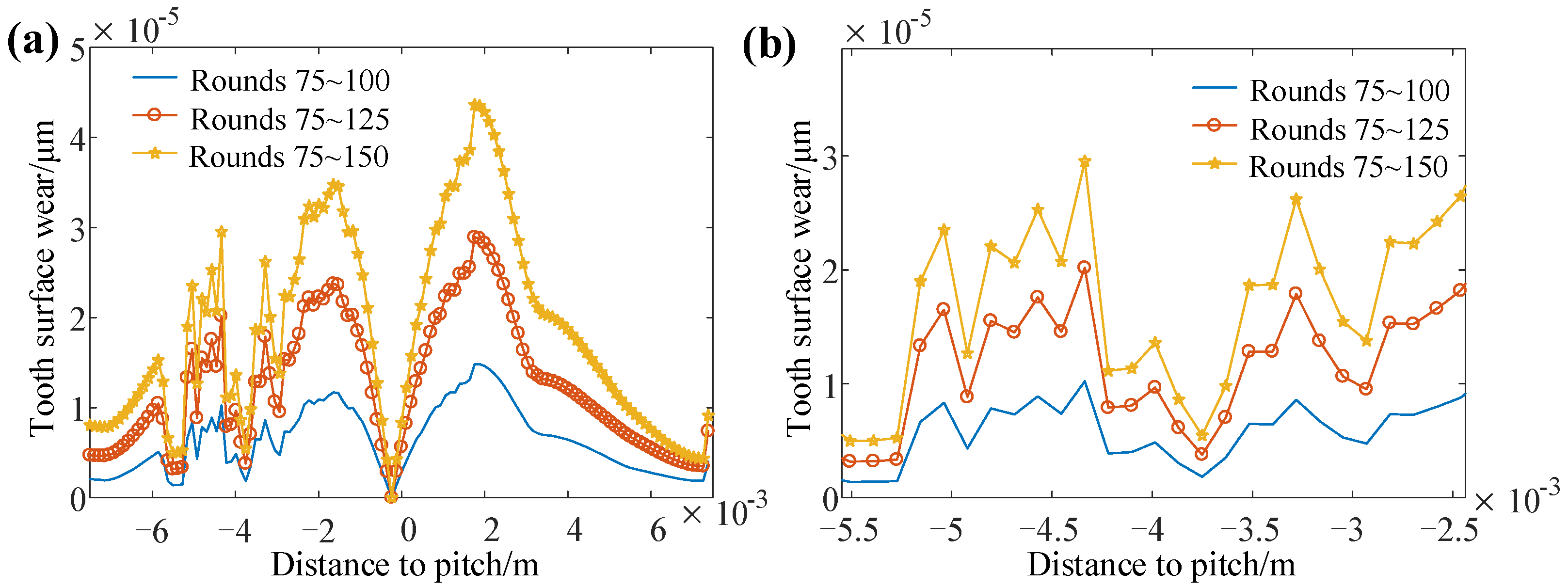
The calculation of dynamic wear is a cumulative process. Since the tooth surface wear of the previous period will affect the wear of the next period, the wear amount and the system response of each period are different. Then, the system responses (system III) of 150 rounds are calculated by using the above parameters. Since the front periods will be affected by the transient response, the dynamic cumulative wear (
Hdynamic) of different rounds with
D = 1.43 is analyzed. Then, the dynamic cumulative wear amount (
Hdynamic) and the system responses are obtained, as shown in
Figure 13,
Figure 14 and
Figure 15.
In
Figure 13, it can be observed that the dynamic cumulative wear (
Hdynamic) increases with the rotation of the gear. Since the number of rounds calculated is small, the difference of tooth surface wear between rounds is not obvious. Thus, the system response (system III) is analyzed in order to study the difference of wear of different rounds.
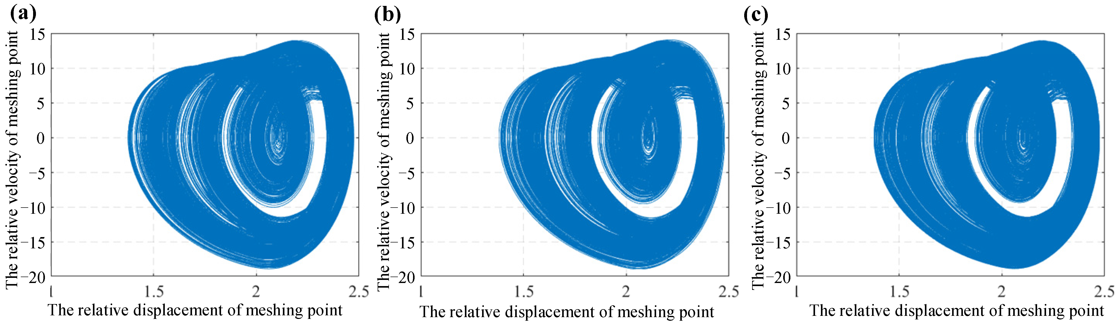
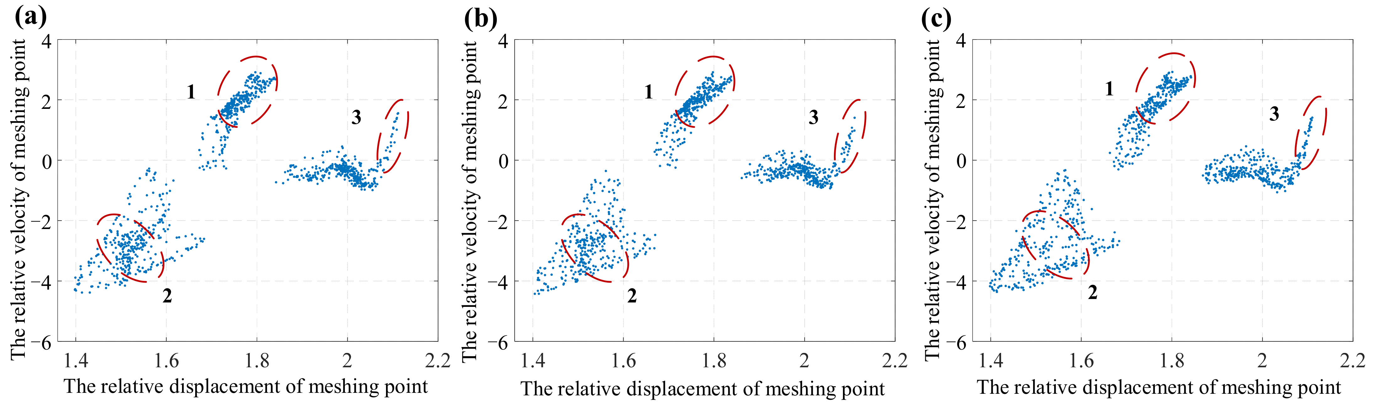
Figure 14a–c represent the phase diagrams obtained by the corresponding displacement and velocities with 75–100, 100–125, and 125–150 rounds, respectively, while
Figure 15a–c represent the Poincare section diagrams obtained by the corresponding displacement and velocities with 75–100, 100–125, and 125–150 rounds, respectively. Then, it can be observed from
Figure 14 that the blank part in the phase diagram decreases with rotation of the gear, which indicates that the displacement and velocity of the system are widely distributed. From
Figure 15, it can be observed that with the rotation of the gear, the concentration of regions 1 and 2 becomes worse, the points in Poincare diagram begin to disperse gradually, and region 3 gradually extends to the distance. All these show that the stability of the system becomes worse, and the accuracy of the dynamic wear model is also proven.
4.3. Influence of μm on the System Response
In the dynamic wear model, in addition to the initial tooth surface wear (
Hinitial) and the number of rounds
n, the meshing stiffness considering the tooth surface flash temperature also has an important influence on the system response. From Equation (2), it can be observed that the friction coefficient
μm of the tooth surface and the relative speed have important effects on the tooth surface flash temperature and then, they affect the stiffness and system response. Due to the difference of meshing forces at different relative speeds, System I is chosen to be calculated. Taking the parameters as
μ = 0.3,
ki = 1,
eg = 0.01,
ζh = 0.01,
ζ1 =
ζ2 =
ζp =
ζg = 0.01,
ep =
eg = 0.01,
e = 0.1,
Fm = 0.105,
Fa = 0.01, and
D = 1.43, the meshing forces at different relative speeds are obtained. Then, the mean values of the meshing forces are shown in
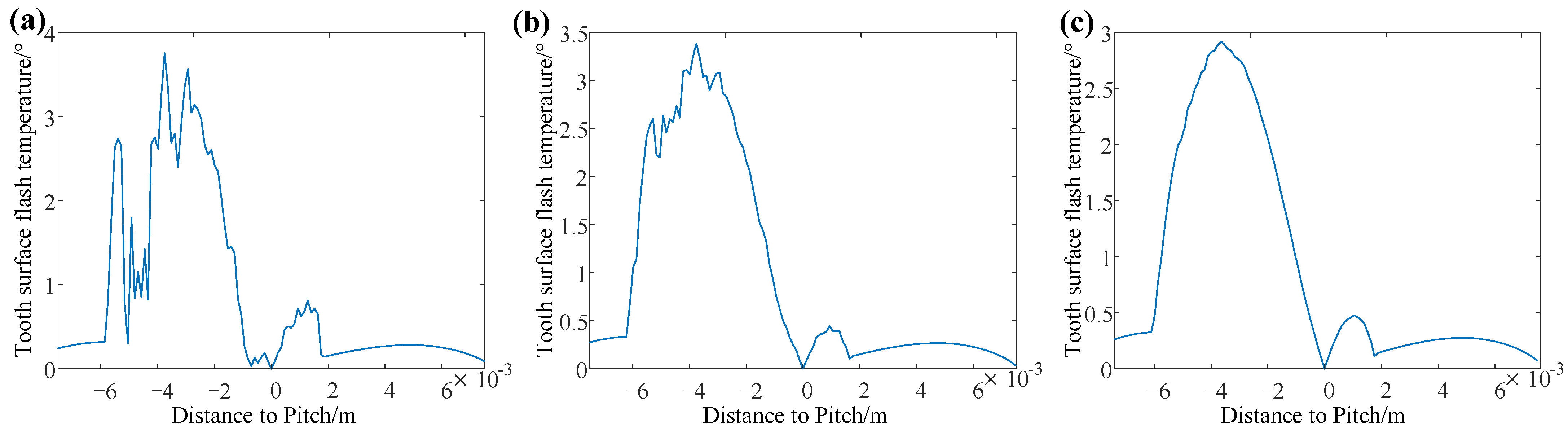
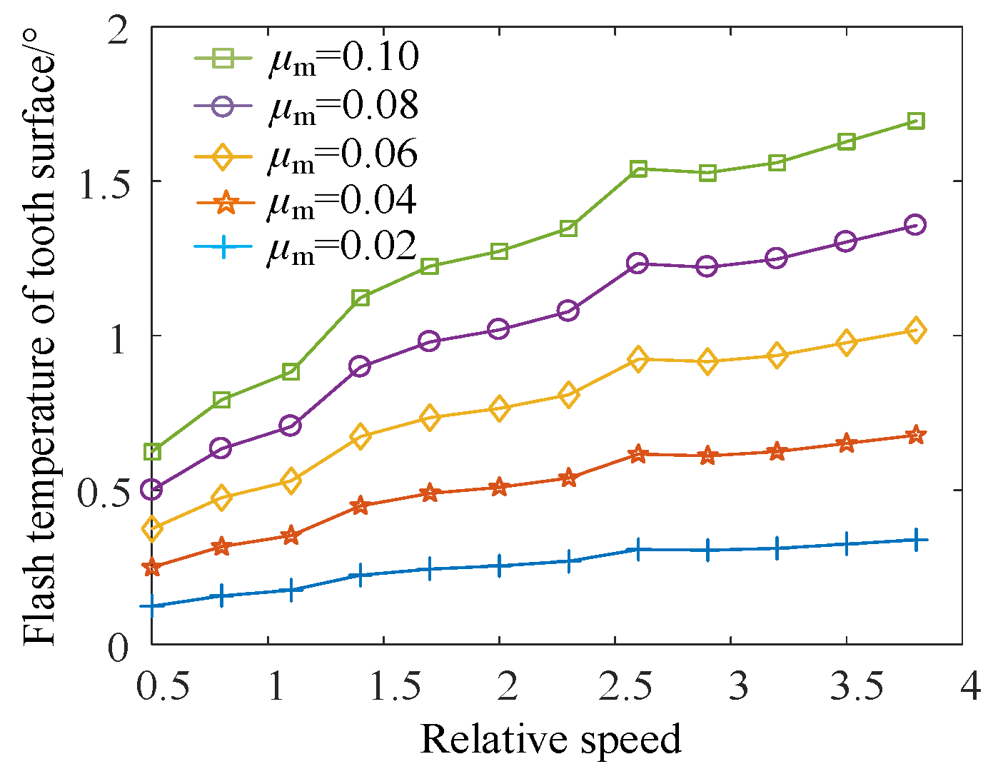
Table 1. Taking the parameters as
ω = 0.5–4,
μm = 0.02–0.1, the tooth surface flash temperature is calculated, which is shown in
Figure 16.
From
Figure 16, it can be observed that the abscissa is the relative speed of the gear system, and different lines represent the tooth surface flash temperature with different friction coefficients. Then, through increasing the relative speed and the friction coefficient, the tooth surface flash temperature increases gradually. Since the meshing force does not increase monotonically, there are some fluctuations in the changing process of flash temperature.
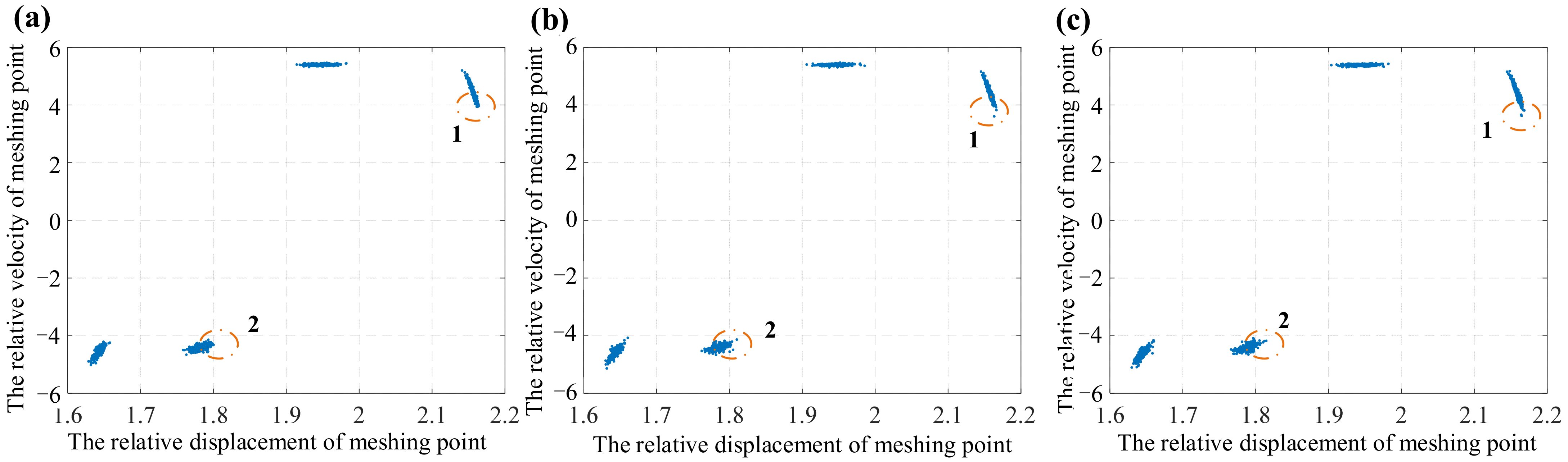
Then, the influence of friction coefficient
μm on the system response (System III) is studied. Taking the parameters as
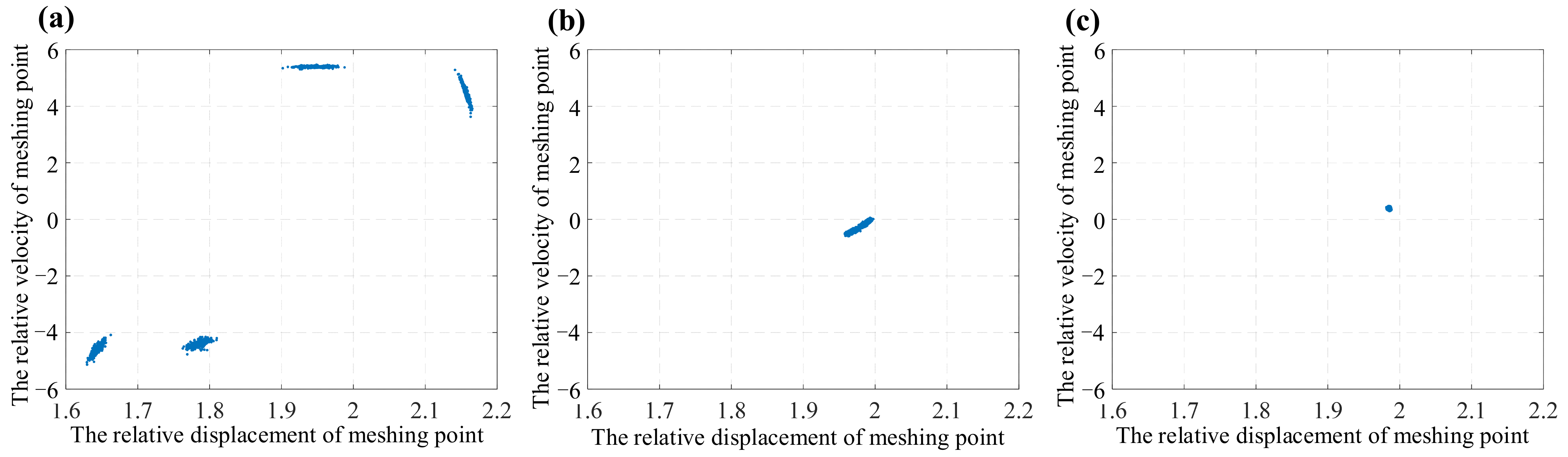
μm = 0.02, 0.06, 0.1, they are substituted into System III, and the Poincare section diagrams are obtained, which are shown in
Figure 17.
It can be observed that when
μm = 0.02, the system response is shown as a set of four regiment points, and the system is in a quasi-periodic motion state at this time. The set of points in regions 1 and 2 is relatively close, and the system is relatively stable. When
μm = 0.06, a small number of points in regions 1 and 2 begin to diffuse outward. Although it is not obvious, that also indicates that the system transforms from a stable to an unstable state. When
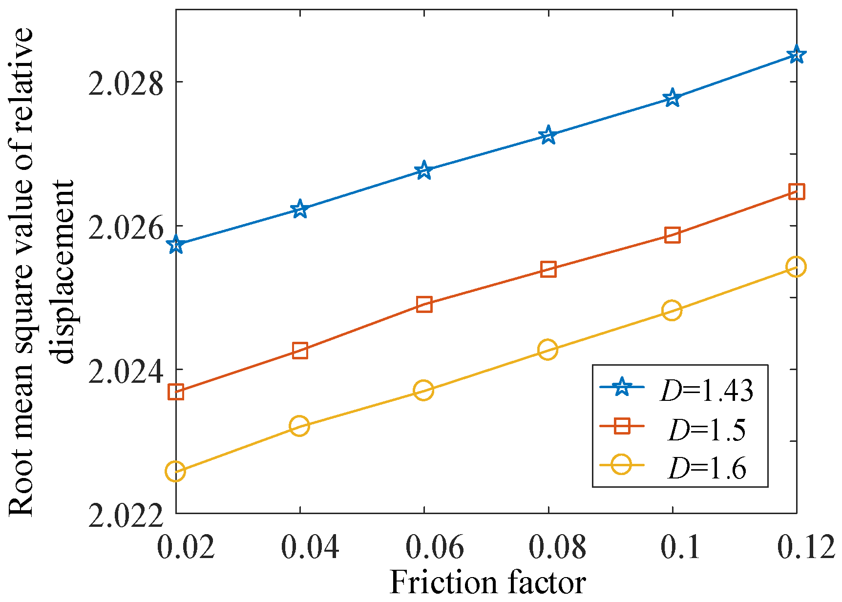
μm = 0.1, many points in regions 1 and 2 break away from the set and diffuse outward, and then, the system tends to be unstable and change to a chaotic motion state. It can be concluded that with an increase of the friction coefficient, the system tends to be unstable. However, the trend is not very obvious. In order to conduct a more detailed and obvious analysis, the root mean square diagrams of system displacement with different friction coefficients are calculated, as shown in
Figure 18.
In the three cases of different initial wear amount (D = 1.43, 1.5, 1.6), taking the parameters as μm = 0.02–0.12, D = 1.43, 1.5, and 1.6, the root mean square values of system displacement are calculated. It can be concluded that the tooth surface flash temperature rises with the increase of friction coefficient. Then, the root mean square value of the vibration displacement of the system amplifies, which indicates that the system tends to be unstable.
4.4. Influence of Damping Ratio on the System Response
The influence of important factors in the dynamic wear model on the system response (System III) is studied in the above sections. Then, in order to analyze the system in detail, the influence of the damping ratio on the system response (System III) is analyzed. Taking the parameters as
μm = 0.06,
μ = 0.3,
ki = 1,
ζh = 0.01,
ζ1 =
ζ2 =
ζp =
ζg = 0.01,
ep =
eg = 0.01,
e = 0.1,
Fm = 0.105,
Fa = 0.01, and
D = 1.43, they are substituted into System III. Then, the phase diagram and the Poincare section diagram are obtained, as shown in
Figure 19,
Figure 20 and
Figure 21.
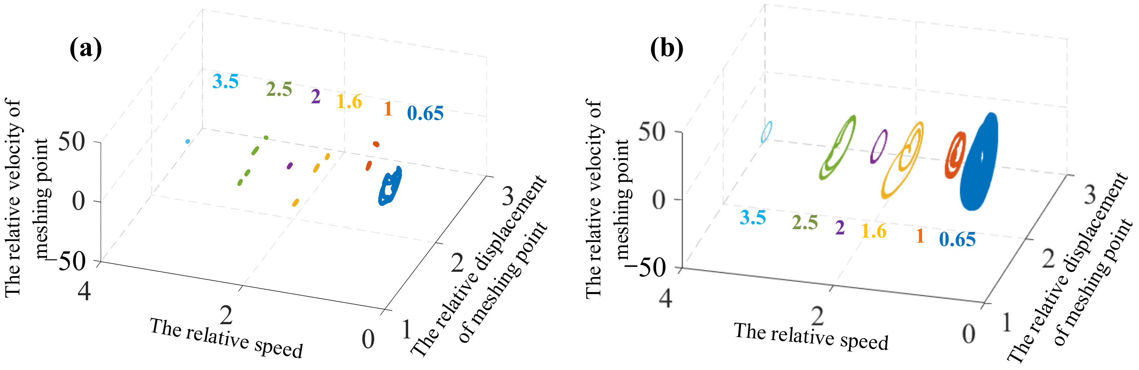
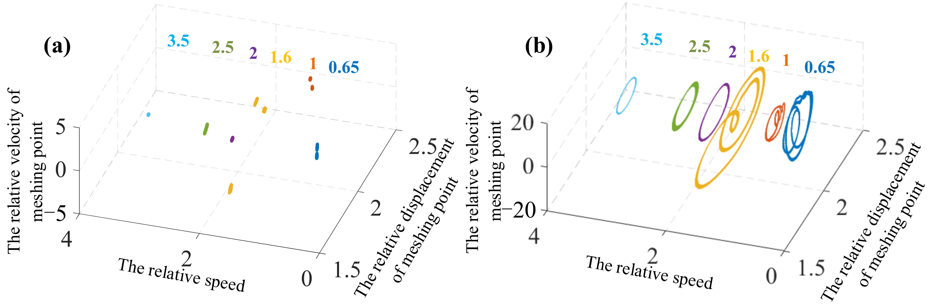
Figure 19 shows the Poincare diagram and the phase diagram with damping ratio
ζ = 0.01. Combined with
Figure 19a,b, it can be observed that the system has experienced chaotic, quasi-double-periodic, quasi-three-periodic, quasi-periodic, quasi-four-periodic and 1T-periodic motion states; when
ζ = 0.05 (
Figure 20), the phase diagram changes to the limit cycle, and the set of points in the Poincare section diagram begins to contract. Then, combined with
Figure 20a,b, it can be observed that the system has experienced 2T-periodic, 3T-periodic, 1T-periodic, and quasi-double-periodic and motion states. Compared to the motion states when ζ = 0.01, the system changes from unstable quasi-periodic and chaotic motion to stable periodic motion; when
ζ = 0.1 (
Figure 21), the system presents stable periodic motion states. Therefore, under the influence of dynamic wear, the increase of damping ratio can also accelerate the energy loss of the system and make the system tend to be stable.
Due to different coordinates of
Figure 19,
Figure 20 and
Figure 21, the transition of motion states is not obvious. The system with relative speed
ω = 2.5 is taken for analysis, and the Poincare section diagrams with
ζ = 0.01, 0.05 and 0.1 are obtained, as shown in
Figure 22. Then, it can be observed that the system gradually changes from quasi four periodic to single periodic, and the system tends to be stable.
5. Conclusions
(1) With the increase of the fractal dimension D, the uncertainty and the amplitude of backlash decrease. Then, the meshing force is reduced, and the wear is small when the gear runs for the same time. The influence on the dynamic wear model is reduced, and the stability of the system considering dynamic wear is enhanced. Therefore, the stable backlash can slow down the tooth surface wear.
(2) The friction coefficient and rotational speed of the tooth surface have an important influence on the temperature of the tooth surface. With the increase of the friction coefficient, the flash temperature and root mean square value of displacement increase, and the system tends to be unstable.
(3) With the increase of the damping ratio, the system changes from unstable quasi-periodic and chaotic motion to stable periodic motion. The increase of damping accelerates the energy loss of the system, makes the system tend to be stable, and has the effect of reducing wear.


