Article

Differential Flatness-Based Cascade Energy/Current Control of Battery/Supercapacitor Hybrid Source for Modern e–Vehicle Applications

1
Renewable Energy Research Centre (RERC), King Mongkut’s University of Technology North Bangkok, 1518, Pracharat 1 Road, Bangsue, Bangkok 10800, Thailand
2
Thai-French Innovation Institute (TFII), King Mongkut’s University of Technology North Bangkok, 1518, Pracharat 1 Road, Bangsue, Bangkok 10800, Thailand
3
Department of Teacher Training in Electrical Engineering (TE), Faculty of Technical Education, King Mongkut’s University of Technology North Bangkok, Bangkok 10800, Thailand
4
Groupe de Recherche en Energie Electrique de Nancy (GREEN), Université de Lorraine, F-54000 Nancy, France
5
Faculty of Electronics, Communication and Computers, University of Pitesti, 110040 Pitesti, Romania
6
ICSI Energy, National Research and Development Institute for Cryogenic and Isotopic Technologies, 240050 Ramnicu Valcea, Romania
*
Authors to whom correspondence should be addressed.
Mathematics 2020, 8(5), 704; https://doi.org/10.3390/math8050704
Submission received: 31 March 2020 / Revised: 17 April 2020 / Accepted: 21 April 2020 / Published: 2 May 2020

Abstract

:
This article proposes a new control law for an embedded DC distributed network supplied by a supercapacitor module (as a supplementary source) and a battery module (as the main generator) for transportation applications. A novel control algorithm based on the nonlinear differential flatness approach is studied and implemented in the laboratory. Using the differential flatness theory, straightforward solutions to nonlinear system stability problems and energy management have been developed. To evaluate the performance of the studied control technique, a hardware power electronics system is designed and implemented with a fully digital calculation (real-time system) realized with a MicroLabBox dSPACE platform (dual-core processor and FPGA). Obtained test bench results with a small scale prototype platform (a supercapacitor module of 160 V, 6 F and a battery module of 120 V, 40 Ah) corroborate the excellent control structure during drive cycles: steady-state and dynamics.

1. Introduction

The crisis of continuously growing fossil fuel costs has provoked transportation industries to advance more efficient automobiles technology. Another solution is to transform technology into other sources including biodiesel or energy from ethanol, etc. Electric vehicles, or hybrid plug-in vehicles, or hybrid vehicles (which are mainly supplied by battery) are a promising solution. Therefore, the electric vehicles (e-vehicle, EVs) industries have designed and developed the technology to progress the extension of EVs [1,2,3]. A lot of research works have been conducted on future vehicle technology [1,2,3]. In EVs, the powertrains are composed of batteries, power converters, and AC electrical motors, such as permanent magnet synchronous motors due to their high energy efficiency, suitable torque-to-weight ratio, and long life span [4,5].
The request for power from battery during dynamic operations can decrease drastically its lifetime [6]. To cope with this challenging issue, the hybridization of batteries with supercapacitors (SC or “ultracapacitor” or “double-layer capacitor”) is an attractive solution. Indeed, SCs feature a high power density compared to batteries, which enables them to respond quickly to dynamic operations [7]. Besides, SCs are compact and have high energy efficiency, particularly fit for automotive applications. However, the combination of SC and battery requires a good control algorithm between these two sources, which is helpful in order to decrease the battery size and to enhance its life span [6,7].
The linear control is generally employed for energy management of the hybrid system. Generally, proportional–integral (PI) compensation is used for energy stability [8,9,10,11,12]. In [13], Marzouguia et al. have proposed a control technique of the hybrid network for a hydrogen electric vehicle (fuel cell car) based on three estimation approaches: first, “a fuzzy logic estimation”; second, “a differential flatness control approach” (model-based technique); third “rule-based algorithm”, making complex the energy management strategy. Indeed, the fuzzy logic controller is employed to manage the energy flows between the main source (i.e., fuel cell) and storage devices (i.e., battery, SC); whereas the flatness controller is used to regulating the DC bus voltage, allowing ensuring the stability of the microgrid. Finally, a rule-based algorithm enables controlling the state-of-charge of SC to keep a good operation of charge/discharge cycles. As a result, the three controllers must interact with each other and their implementations are more complex.
On the other side, batteries and SCs are interfaced with the DC bus through classic buck–boost converters, making them unavailable in case of power switch failures. These converters are controlled based on PI-current control laws. The parameters for PI controllers have been designed and tuned in agreement with the linear optimum technique, requiring classic linear approximations contingent on the defined equilibrium point. Hence, the performances can be guaranteed only for specific operating cases.
Since the hybrid system includes bidirectional DC–DC converters linked to storage devices, the power converter model is nonlinear behavior. Then, it is important to use a nonlinear model-based control approach to the balance of the nonlinearity of the power electronics network [13]. In [14], Song et al. have developed an energy management algorithm for an electric vehicle supplied by batteries and SCs. Two algorithms are used: one based on Lyapunov-function regulation to stabilize the DC bus, and another based on a sliding mode approach to regulate both classic 2-quadrant converters connected to power sources, making them less reliable in case of electrical failures. It has to be noted that availability and reliability are currently major concerns so that EVs must access the mass automotive market. On one hand, the use of sliding mode controllers allows ensuring excellent performances to control both the charge/discharge of batteries and SC. On the other hand, the development of the Lyapunov function to make it stable for any operating scenario is a challenging issue.
In [15], Zhang et al. have applied a real-time unified speed regulation and control technique of a hybrid car supplied by batteries and SCs. The developed strategy is based on the Lyapunov nonlinear control technique. However, only simulation results have been reported to validate the developed control strategy. Furthermore, compared to the work reported in [14], the Lyapunov-based controller has several objectives such as the speed control of the AC motor and the energy management of batteries and SC (i.e., reducing battery stress, and extending battery lifetime). Since the controller must meet both objectives, its stability must be analyzed thoroughly to ensure good dynamic performances.
Next, Fliess et al. [16] were the first to develop differential flatness estimation (nonlinear approach). This approach has enabled the system to be an alternative representative, of which motion planning and regulator tuning is clear-cut. This theory has lately been utilized in a variety of networks in different scientific domains [17,18,19,20,21,22,23]. Compared to the nonlinear algorithm (i.e., sliding mode, Lyapunov, fuzzy logic) reported in [13,14,15], nonlinear algorithms based on differential flatness require the use of trajectory planning to implement the control laws. This trajectory planning aims at controlling different variables (e.g., currents of converters, stored energy in the DC bus and SC) to manage the energy in an EV while optimizing the performance of the system for any operating point. The use of this algorithm allows ensuring the robustness of energy management to meet the requirements of EVs (e.g., dynamic performances, the extension of the lifetime of storage devices).
For clarity, Figure 1 presents experimental results from the laboratory comparing the nonlinear differential flatness estimation and the classic PI control law during the great changed current set-point [17] of 3-phase inverter control. From these test-bench results, the differential flatness-based estimation approach presents the excellent response of the current control to its set-point iqREF from step 1 A to 6 A. For this reason, it can be concluded that differential flatness control offers better dynamics than the traditional PI regulator.
So far, algorithms based on differential flatness have been successfully applied to power converters (e.g., 3-phase inverter and rectifier, interleaved boost converter, modular multilevel converter) [17,18,20,21], permanent magnet synchronous motor and AC servomotor [19,22,23]. Based on these previous works, the purpose of this article is to extend the use of differential flatness algorithm in an embedded DC microgrid (i.e., EV powertrain) to manage optimally its operation during static and dynamic operations. It has to be noted that the implementation of this algorithm is challenging since several variables have to be controlled to meet some expectations from the dynamic performances and stability point of view.
In this work, following the introduction part in section 1, Section 2 is detailed on the presentation of the hybrid power source–Battery/SC devices: power converter circuits and system equations. Afterward, in Section 3, energy management strategy (inner current control loops and outer energy control loops) and control laws are provided. Finally, in Section 4, an experimental test bench results are given to corroborate the proposed control law.

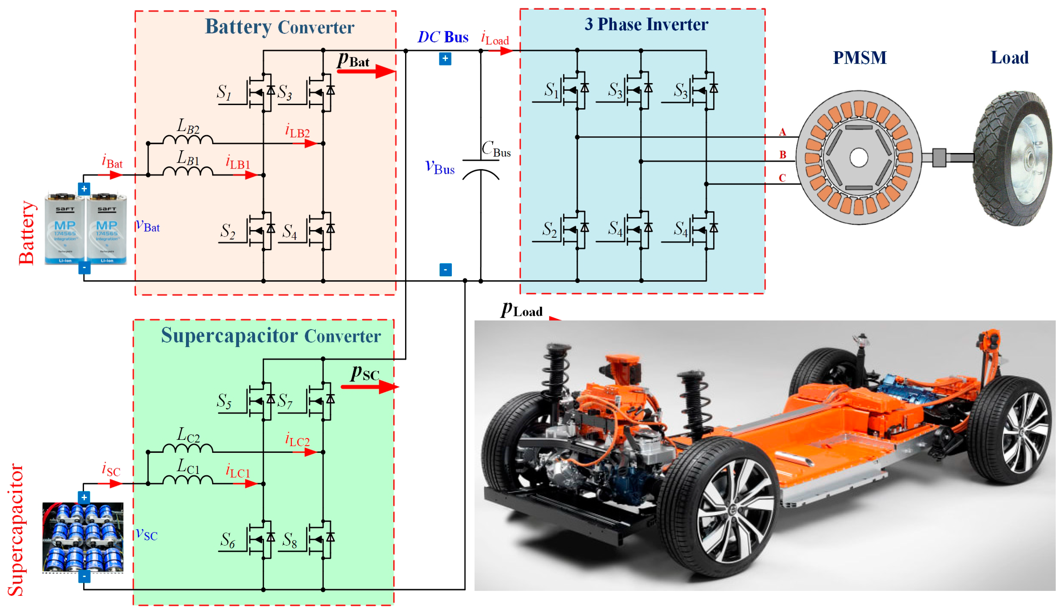
2. Hybrid Power Source

2.1. Power Converter Structure

SC and Battery power modules are frequently combined with buck–boost DC–DC converters (or 2-quadrant converters) to allow the charge and discharge of the storage devices. However, these converter cells are restricted when increasing power scale or when a high voltage gain is requested. Besides, the availability and reliability of electric vehicles is an important issue, which cannot be met by using a classic buck–boost converter. Therefore, the parallel power converters (parallel multi-phase converters as shown in Figure 2) with the interleaved technique are particularly suitable to meet the abovementioned issues [24,25,26]. The load at the DC bus is a 3-phase inverter driving a three AC motor [induction motor or permanent magnet synchronous motor (PMSM)], as a vehicle traction drive.

2.2. Power Plant Modeling

The interleaved switching algorithm consists of the phase shift control signal of multiple converter modules (N) connecting in parallel [24,25,26]. In this article, two-phase interleaved buck–boost converters (N = 2) have been chosen to carry out this work. Indeed, by choosing only two phases, the shift control signal is equal to 180° and be easily achieved by using a prototyping dSPACE board (employed for experiment purposes). The differential equations of the two-phase buck–boost converters for SC and battery modules when the converter operates in continuous conduction mode may be expressed as [27]:
di LB 1 dt = 1 L LB 1 [ v Bat ( 1 d 1 ) × v Bus r LB 1 × i LB 1 ]
di LB 2 dt = 1 L LB 2 [ v Bat ( 1 d 2 ) × v Bus r LB 2 × i LB 2 ]
di LC 1 dt = 1 L LC 1 [ v SC ( 1 d 3 ) × v Bus r LC 1 × i LC 1 ]
di LC 2 dt = 1 L LC 2 [ v SC ( 1 d 4 ) × v Bus r LC 2 × i LC 2 ]
dv Bus dt = 1 C Bus [ ( 1 d 1 ) × i LB 1 + ( 1 d 2 ) × i LB 2 + ( 1 d 3 ) × i LC 1 + ( 1 d 4 ) × i LC 2 i Load ]
where the subscripts B1, B2, C1, C2 are parameters of each cell connected to the battery (B) or SC (C); iLoad is the load current; vSC is the SC voltage; vBat is the battery voltage; iL is the inductor current; CBus is the total capacitance at the DC grid; L is the inductance, rL is the parasitic resistor of the inductor; and d is the controlled duty cycle of the pulse width modulation (PWM) for power circuit. This model is simplified to carry out this work since it does not take into account some type of losses generally met in DC–DC converters (dynamics losses, switching dead-time, etc…) [28].
The SC and battery currents are assumed to follow their desired set-points completely. In consequence,
i Bat = i BatREF = p Bat v Bat = p BatREF v Bat
i SC = i SCREF = p SC v SC = p SCREF v SC
The DC grid electrostatic energy EBus and the SC electrostatic energy ESC is given by [13]:
E Bus = 1 2 × C Bus × v 2 Bus
E SC = 1 2 × C SC × v 2 SC
The total stored energy ET in the SC CSC and in the DC bus capacitor CBus can be expressed by the following expression:
E T = 1 2 × C Bus × v 2 Bus + 1 2 × C SC × v 2 SC
Based on Figure 2, the differential equation of power balance is given as follows [6]:
E ˙ Bus = p Bato + p SCo p Load
where
p Bato = p Bat r Bat ( p Bat v Bat ) 2
p SCo = p SC r SC ( p SC v SC ) 2
p Load = v Bus × i Load = 2 E Bus C Bus × i Load
p SC = v SC × i SC = 2 E SC C SC × i SC

3. Control Structure and Control Laws

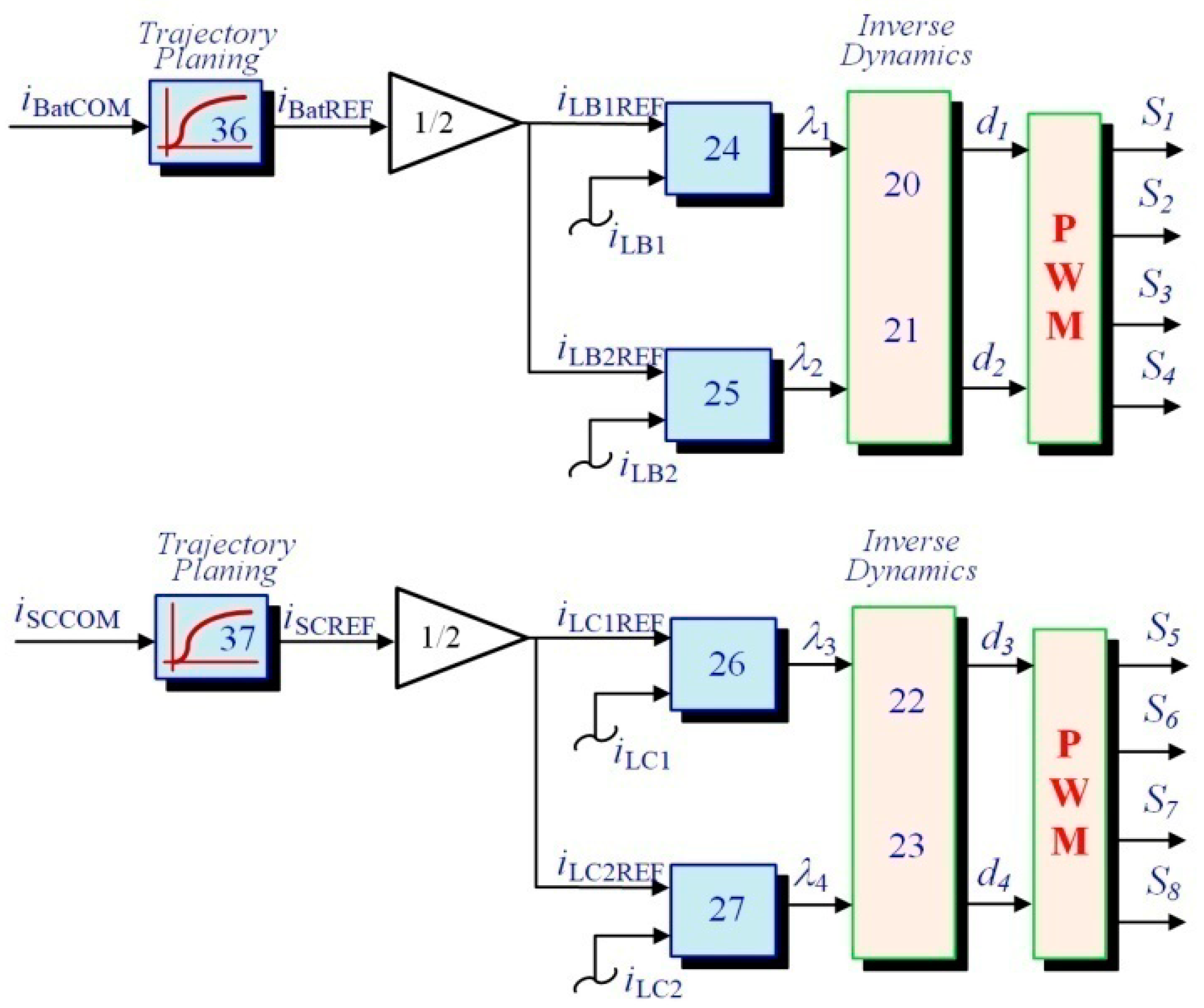
3.1. Inner Current Regulations

To evaluate if the studied network is flat [19,20], one defines the flat vector output variables: y1, y2, y3, y4; state vector variables: x1, x2, x3, x4; and control vector variables: u1, u2, u3, u4 as:
y 1 = i LB 1 ; y 2 = i LB 2 ; y 3 = i LC 1 ; y 4 = i LC 2
u 1 = d 1 ; u 2 = d 2 ; u 3 = d 3 ; u 4 = d 4
x 1 = i LB 1 ; x 2 = i LB 2 ; x 3 = i LC 1 ; x 4 = i LC 1
Hence, the state vector variables: x1, x2, x3, x4 may be expressed as:
x 1 = φ 1 ( y 1 ) ; x 2 = φ 2 ( y 2 ) ; x 3 = φ 3 ( y 3 ) ; x 4 = φ 4 ( y 4 )
From (1) to (4) and (16) to (18), the control vector variables of u are assessed from the flat output variables y and its time derivative [19]:
u 1 = d 1 = 1 + 1 v Bus ( L y ˙ 1 v Bat + r LB 1 × y 1 ) = ψ 1 ( y 1 , y ˙ 1 )
u 2 = d 2 = 1 + 1 v Bus ( L y ˙ 2 v Bat + r LB 1 × y 2 ) = ψ 2 ( y 2 , y ˙ 2 )
u 3 = d 3 = 1 + 1 v Bus ( L y ˙ 3 v SC + r LC 1 × y 3 ) = ψ 3 ( y 3 , y ˙ 3 )
u 4 = d 4 = 1 + 1 v Bus ( L y ˙ 4 v SC + r LC 1 × y 4 ) = ψ 4 ( y 4 , y ˙ 4 )
The desired references of inductor current of each phase iLB1, iLB2, iLC1, iLC2 are defined by y1REF (=iLB1REF), y2REF (=iLB2REF), y3REF (=iLC1REF), y4REF (=iLC2REF). Control laws (feedback regulation) reaching an exponential following of the references are written as [19,29]:
( y ˙ 1 y ˙ 1 REF ) + K i 11 ( y 1 y 1 REF ) + K i 12 0 t ( y 1 y 1 REF )   d τ = 0
( y ˙ 2 y ˙ 2 REF ) + K i 21 ( y 2 y 2 REF ) + K i 22 0 t ( y 2 y 2 REF )   d τ = 0
( y ˙ 3 y ˙ 3 REF ) + K i 31 ( y 3 y 3 REF ) + K i 32 0 t ( y 3 y 3 REF )   d τ = 0
( y ˙ 4 y ˙ 4 REF ) + K i 41 ( y 4 y 4 REF ) + K i 42 0 t ( y 4 y 4 REF )   d τ = 0
where Ki11, Ki12, Ki21, Ki22, Ki31, Ki32, Ki41, and Ki42, are the regulation parameters. A set dynamic polynomial can set the following as [30]:
p 1 ( s ) = s 2 + 2 ζ 1 ω n 1 s + ω n 1 2
p 2 ( s ) = s 2 + 2 ζ 2 ω n 2 s + ω n 2 2
p 3 ( s ) = s 2 + 2 ζ 3 ω n 3 s + ω n 3 2
p 4 ( s ) = s 2 + 2 ζ 4 ω n 4 s + ω n 4 2
K i 11 = 2 ζ 1 ω n 1 ; K i 12 = ω n 1 2
K i 21 = 2 ζ 2 ω n 2 ; K i 22 = ω n 2 2
K i 31 = 2 ζ 3 ω n 3 ; K i 32 = ω n 3 2
K i 41 = 2 ζ 4 ω n 4 ; K i 42 = ω n 4 2
where ζ1, ζ2, ζ3, ζ4, ωn1, ωn2, ωn3, and ωn4 are the chosen damping ratio and defined natural frequency. Therefore, new variables are determined λ 1 = y ˙ 1 ; λ 2 = y ˙ 2 ; λ 3 = y ˙ 3 ; λ 4 = y ˙ 4 .
The flatness-based control requires trajectory planning to implement the control law. Hence, a second-order filter has been chosen to set the battery and SC currents, dynamics commands iBatCOM, iSCCOM as the following equations [19]:
i BatREF ( s ) i BatCCOM ( s ) = 1 ( s ω nt 1 ) 2 + 2 ζ t 1 ω nt 1 s + 1
i SCREF ( s ) i SCCCOM ( s ) = 1 ( s ω nt 2 ) 2 + 2 ζ t 2 ω nt 2 s + 1
where ωnt1, ωnt2, ζt1, and ζt2, are again the desired natural frequency and dominant damping ratio, refer to Figure 3.

3.2. Outer Energy Controls

The energy control law for the studied system shown in Figure 2 consists of using two energy control laws which include DC link energy EBus and SC energy ESC by two voltage variables to be regulated. Thus, based on the literature review [6,31,32], the first priority variable to be regulated is EBus and ESC is a secondary variable. Given that the fastest dynamic power source of the studied system is the SC, it has been decided to use this device to supply energy to the DC link. On the other side, since the slowest dynamic power source is the battery, the latter has been chosen to provide the energy to both the SC CSC and the DC bus capacitor CBus to store energy.
The flat output y5, y6, state variable x5, x6 and control variable u5, u6 can be expressed as follows [6]:
y 5 = E Bus ; y 6 = E T
u 5 = p SCREF ; u 6 = p SCREF
x 5 = v Bus ; x 6 = i SC
x 5 = 2 y 5 C Bus = φ 5 ( y 5 )
x 6 = ( 2 y 6 y 5 ) C SC = φ 2 ( y 5 , y 6 )
By using (8)–(15), the control input vector u may be computed from the flat output variable y and its time derivatives [6]:
u 5 = 2 p SC Max [ 1 1 y ˙ 5 + 2 y 5 C Bus × i Load p Bato p SCMax ] = ψ 5 ( y 5 , y ˙ 5 ) = p SCREF
u 6 = 2 p T Max [ 1 1 y ˙ 6 + 2 y 6 C Bus × i Load p TMax ] = ψ 6 ( y 6 , y ˙ 6 ) = p T REF
where
p SCMax = v 2 SC 4 r SC , p TMax = v 2 T 4 r T
In this case, pTMax and pSCMax correspond to the set limited power of the SC and battery devices (maximum power), respectively.
In the first energy control law, the set-point for the DC link energy is defined by y5REF. The closed-loop control law is written by the following expression:
y ˙ 5 y ˙ 5 REF + K v 1 ( y 5 y 5 REF ) + K v 2 0 t ( y 5 y 5 REF ) d t = 0
where Kv1 and Kv2 are the controller parameters. The suitable way to tune these parameters is achieved by corresponding the desired dynamic polynomial p(s), with set root positions. One can set the following equations:
p 5 ( s ) = s 2 + 2 ζ 5 ω n 5 s + ω n 5 2
K v 1 = 2 ζ 5 ω n 5 ; K v 2 = ω n 5 2
where ωn5 and ζ5 are the chosen natural frequency and dominant damping ratio.
The control law of the DC link energy regulation detailed previously is displayed in Figure 4. The proposed control law generates an SC power desired variable pSCREF. Next, this signal is divided by the SC voltage vSC and restricted to keep the SC voltage within the gap [maximum VSCMax, minimum VSCMin] by limiting the SC module discharging current or charging current, as shown in the block “SuperC Current Limitation Function” [32]. Then, this becomes SC current command iSCCOM.
Second, for the total energy control law (charging SC), the set-point is represented by y6REF. Indeed, the SC energy has been set as slower dynamics than the DC link energy and the SC device features a high energy storage capacity. Again, the feedback control law is expressed as follows:
y ˙ 6 y ˙ 6 REF + K v 3 ( y 6 y 6 REF ) = 0
Refer to Figure 5, the proposed control law based on the differential flatness approach estimates the battery power set-point pBatREF. Then, it is divided by the battery sensor voltage vBat and generates the battery current command iBatCOM, limited within iBatMax and iBatMin (=0 A).
Finally, the soft-start system in the smooth transition point of view, the energy command has to be generated for the converter and restricted set-point profiles for smooth transforms between operating points. The trajectory motion planning for the reference signals EBusREF and ETREF are written as [19]:
y BusREF ( s ) y BusCOM ( s ) = 1 ( s ω nt 3 ) 2 + 2 ζ t 3 ω nt 3 s + 1
y SCREF ( s ) y SCCOM ( s ) = 1 ( s ω nt 4 ) 2 + 2 ζ t 4 ω nt 4 s + 1
where ωn3, ωn4, ζt3, and ζt4 are the chosen natural frequency and dominant damping ratio.

4. Performance Validation

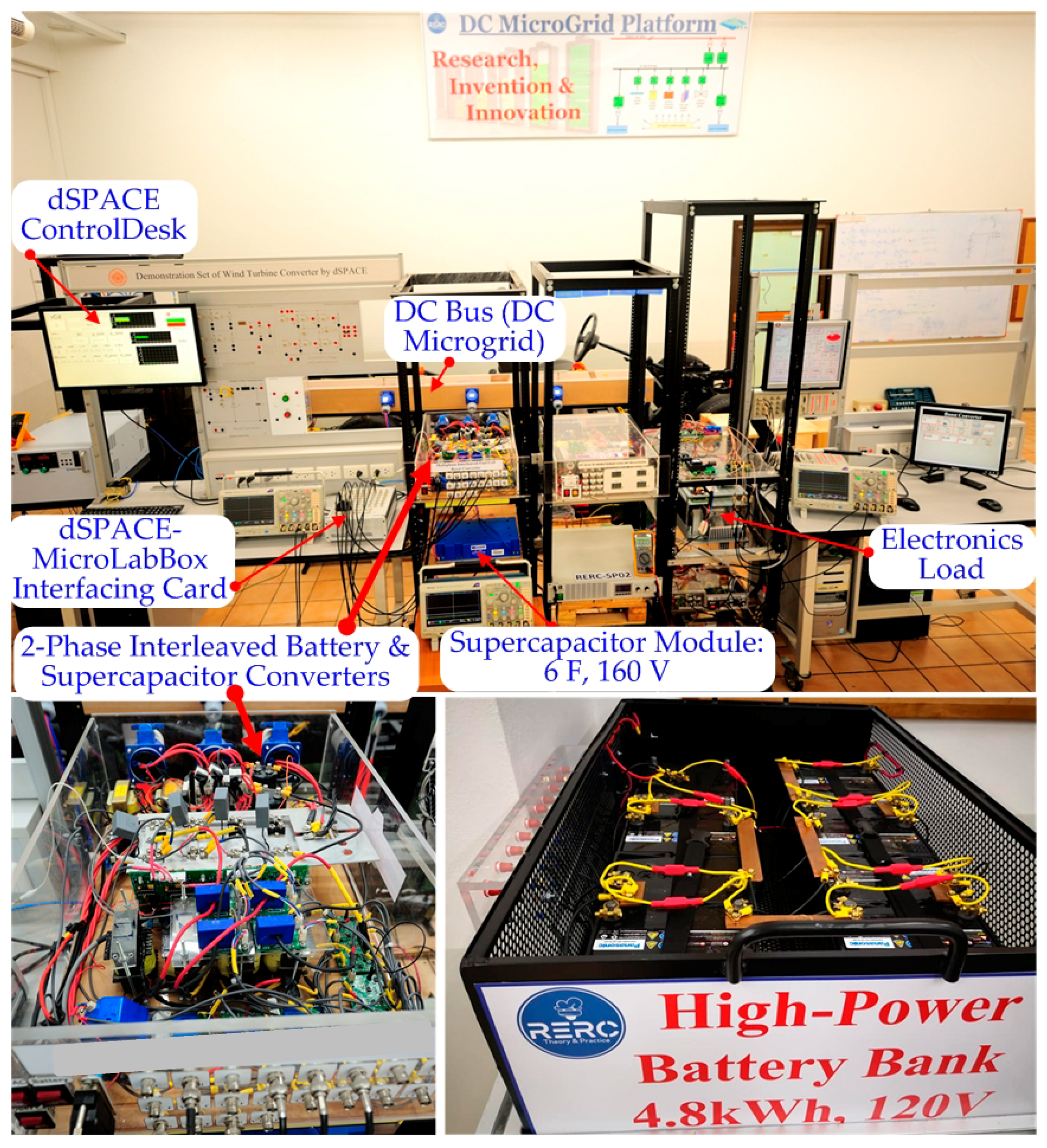
4.1. Test Bench Setup and Flatness Control Parameters

To validate the effectiveness of the studied control algorithm for system management in an embedded DC microgrid, an experimental platform has been realized in the Renewable Energy Research Centre (RERC) at King Mongkut’s University of Technology North Bangkok, as presented in Figure 6. The DC–DC converter circuit parameters are provided in Table 1. The SC module is 160 V, 6 F, (BMOD0006 E160 B02—Maxwell Technologies Company) and the battery module is 40 Ah, 120 V (Panasonic Technology). The studied DC link voltage is 310 V, meeting the high DC grid voltage requested for automotive applications. The inner current regulation parameters are given in Table 2. Parameters related to the outer energy control parameters are shown in Table 3 and Table 4, respectively. Additionally, the battery current slope control can be seen in Table 4. This number has been approved by experimental results to have the highest slope of the battery device. Besides, the proposed control algorithm (based on Figure 3, Figure 4 and Figure 5), which generates desired duty cycle signals d for both interleaved buck–boost converters, and regulates the total stored energy (including the DC bus and SC), has been realized in MATLAB®—Simulink environment. Then, it has been implemented into the real-time board DS1202 dSPACE−MicroLabBox (2 GHz dual-core real-time microprocessor and user-programmable Field-Programmable Gate Array FPGA) with the sampling frequency (timer interrupt) of 25,000 Hz. This value is related to the high switching frequency of both interleaved buck–boost DC–DC converters.
Firstly, the oscilloscope waveforms in Figure 7 and Figure 8 show the steady-state switching behaviors of the studied interleaved 2-quadrant DC–DC converters for the battery and SC module at different current references. In Figure 7, the following signals are available:
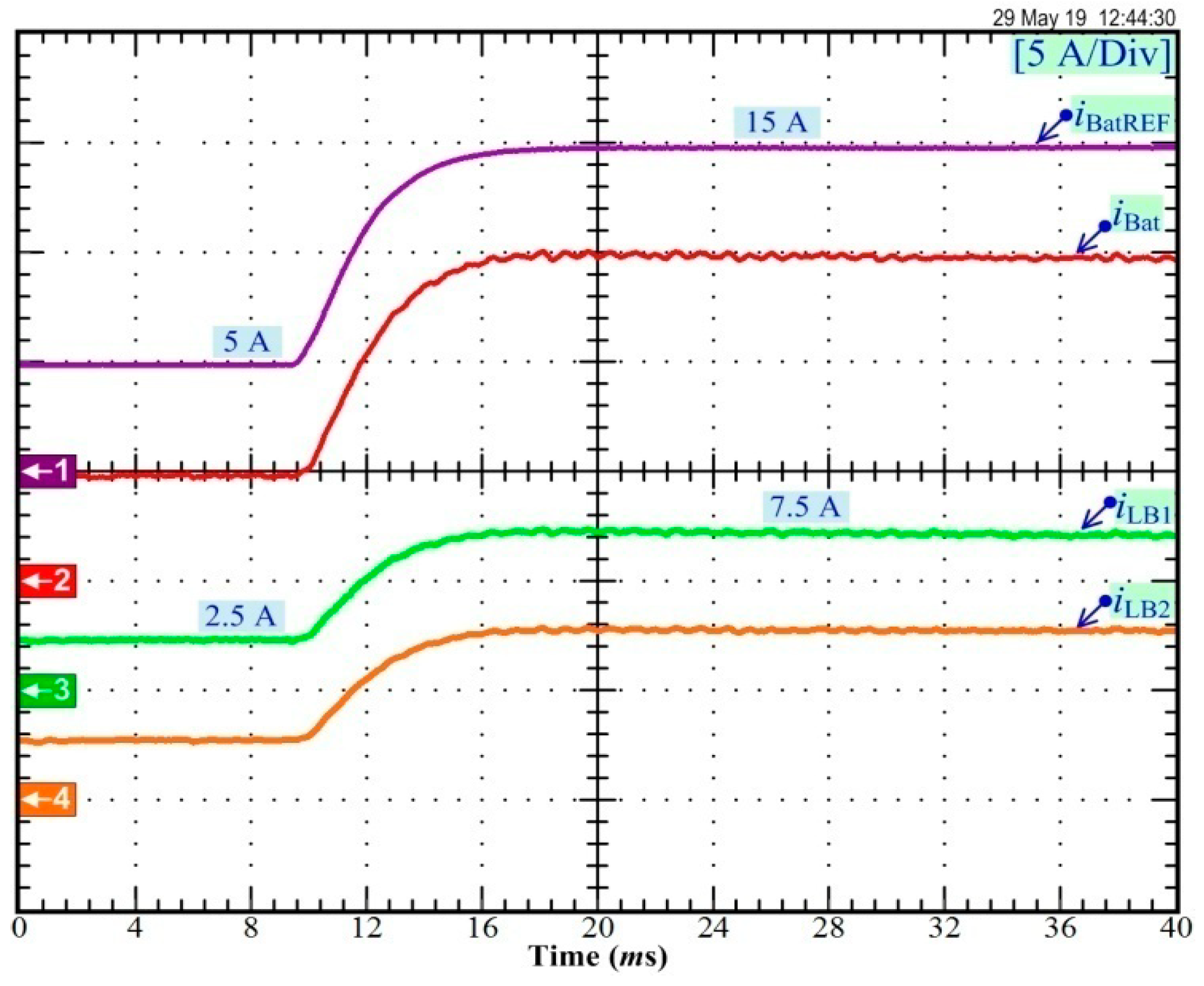
  • Ch1: the battery current set-point iBatREF at +20 A (battery discharging mode);
  • Ch2: the measured battery current iBat;
  • Ch3: the 1st inductor current iLB1;
  • Ch4: the 2nd inductor current iLB2.
The obtained results show iLB1 and iLB2 where their average values are equal to iBatREF/2 (i.e., 10 A). It can be observed that the current of the iBat battery is the sum of iLB1 and iLB2. It is equal to 20 A according to iBatREF, but there is a small current ripple due to the use of an interleaved buck–boost converter.
Then, Figure 8 presents the experimental results in charge mode of the SC at 15 A or iSCREF = −15 A. In Figure 8, the following measurements are available:
  • Ch1: the SC current set-point iSCREF;
  • Ch2: the measured SC current iSC;
  • Ch3: the 1st inductor current iLC1;
  • Ch4: the 2nd inductor current iLC2.
The current iSC is equal to iSCREF and is close to a pure DC current. The iLC1 and iLC2 have a very small ripple, with an average value of iSCREF/2 equal to −7.5 A.
In Figure 9, it is shown the dynamics response when the battery reference iBatREF increases instantaneously from initial +5 A to final +15 A. The following signals are available:
  • Ch1: the battery reference iBatREF;
  • Ch2: the measured input battery current iBat;
  • Ch3: the 1st inductor current iLB1;
  • Ch4: the 2nd inductor current iLB2.
First of all, it can be seen that the current iBat follows perfectly the reference iBatREF. As a result of the operating conditions change, the response of the current iBat is damped due to the use of a 2nd order filter equation. Like in the previous results, the battery current iBat (=iBatREF) is the summation of iLB1 and iLB2.
Finally, Figure 10 shows the dynamics response by modifying the equilibrium points of the SC current from 5 A to −5 A. The following signals are available:
  • Ch1: the SC current reference iSCREF;
  • Ch2: the measured SC current iSC;
  • Ch3: the 1st inductor current iLC1;
  • Ch4: the 2nd inductor current iLC2.
It can be noted that the reference iSCREF has a steep slope (2nd order filter characteristics) and the current iSC follows iSCREF completely, with a low settling time of 10 ms.

4.2. Hybrid Power Plant Load Cycles

To assess the performance of the differential flatness-based controller in regulating the DC bus energy by using SC, dynamic tests were carried out by modifying the load power from 0 W to 3 kW. The obtained results are shown in Figure 11, providing the DC bus voltage vBus, the SC voltage vSC, the load power (disturbance) pLoad, and the SC power pSC in transient and steady-state operation. Given that the first operating condition does not consider any load (i.e., from 0 to 120 ms), the storage device is full of charge (vSCREF = vSC = 140 V), and the DC link voltage is controlled at 310 V (vBusREF = vBus = 310 V). Hence, the SC and battery powers are zero. Since the battery power is set to pBatREF = 0 (see Figure 5), the role of SC module to maintain the DC bus voltage stability can be examined.
After that, at t = 120 ms, the load power (disturbance) instantly changes from 0 W to 3 kW (positive transition ↑). It can be observed that the SC module provides the steady-state and dynamics load power demand. The DC bus voltage is slightly influenced by the large load disturbance by utilizing the nonlinear differential flatness-based estimation for the proposed system.
Then, Figure 12 presents experimental results during a load drive cycle. Here, the electronic load has been changed to emulate the electric vehicle characteristics: overload, positive power (acceleration mode) or negative power (regenerative braking), and positive and negative transients. This Figure depicts the DC bus voltage vBus, the battery voltage vBat, the load power pLoad, the battery power pBat, the SC power pSC, the battery current iBat, the SC current iSC, and the SC voltage vSC (represents the SC state-of-charge). Like in Figure 11, it can be noted that the DC bus voltage is not impacted by the large perturbation.
At the beginning, the load power = 600 W and the SC module is likewise full-of-charge (vSC = vSCREF = 140 V); consequently, the battery power is equal to 600 W for the load; while the SC is the second source, of which its power is equal to zero.
At t1, the load power changes from 600 W to the 3600 W (overload, high energy requested by the load). The following explanation can be made:
1. The SC provides power most of the dynamic large load of 3600 W.
2. Concurrently, the battery power goes up to a limited level (maximum value setting) of 2100 W at t2.
3. The SC device provides most of the power dynamics that are requested during the load step and continue in discharge mode.
After that at t3, the load power demand decreases drastically from 3600 to 600 W; consequently, the SC module changes its operating mode from discharging to charging. It can be noted that:
1. The battery remains constant supplying its maximum power (limited power) of around 2100 W. It means the battery provides powers to load and charge the SC module.
2. At t4 (vSC = 130 V), the SC module is almost charged at 140 V, and afterward, the SC power decreases. Accordingly, the battery power is reduced gradually.
3. At t5, the SC is full of charge at 140 V; after that, the SC current is zero. Synchronously, the battery main source provides only energy to the load 600 W.
Afterward, at t6, the load power changes from 600 W to −600 W to emulate vehicle braking. The SC is extremely charged and recovers the energy at the DC bus; concurrently, the battery power declines (with a limited slope) to zero.
At t7, the SC absorbs the negative power provided only by the load. Thus, the SC is in overcharged state, i.e., vSC > vSCREF = 140 V.
Subsequently, at t8, the load power changes immediately from −600 W to +600 W, where vSC = 155 V (overcharged); therefore, the SC modules changes its operating mode from charging to discharging and the battery remains in idle state (the current limitation at 0 A). Therefore, the requested load power is provided by only the SC source.
At t9, when vSC reaches vSCREF equal to 140V, the SC power drops to 0 W; then, the battery current increases to provide the power for the load requested.
At t10, the battery power remains at a constant level of 600 W.
Finally, at t11, the load power changes from 600 W to zero (stop mode). The SC recovers the energy and the battery power decreases to zero. It can be concluded that the hybrid network enables keeping energy balance by using the proposed energy control law.

4.3. Comparison of the Performances Compared to the Previous Works

As highlighted in the introduction, the previous works reported in [13,14,15] have been focused on the energy management of electric vehicles based on various nonlinear algorithms (e.g., sliding mode, Lyapunov, fuzzy logic). However, only in [13,14], the developed control algorithms have been validated experimentally on load power profile. Both load power profiles present the same dynamic operations (i.e., three acceleration modes and one braking mode); whereas the chosen load power profile in this work includes one acceleration and braking operation as shown in Figure 12. The dynamic performances obtained both for batteries and SC are close to those obtained in [14]. In comparison, reported results in [13] show that the responses of sources (i.e., batteries, SC) to different dynamics are slower. Indeed, since PI current controllers are used to control both buck–boost converters connected to the sources, the required time to track the different references are longer. In conclusion, the algorithms based on Lyapunov-function and sliding mode controllers or differential flatness offer excellent dynamic performance while preserving the good operation of the storage devices against fast dynamics and keeping the stability of the DC bus. Besides, the use of interleaved buck–boost converters allows reducing the current ripple (as shown in Figure 9 and Figure 10) and ensuring the availability of both converters in case of power switch failures.

5. Conclusions

The key objective of this work is to study new energy management of supercapacitor/battery hybrid sources for modern electric transportation applications. The combination of battery and ultracapacitor is suitable for the hybridization network since it offers high power and high energy densities. The control law allows avoiding the fast dynamic current transient of battery and decreasing the battery stresses. For this reason, the proposed hybrid system allows optimizing its life span. However, this issue does not come within the scope of this article to reveal the battery’s lifetime.
The developed control strategy has been tested with an experimental prototype platform implemented in the laboratory, including a battery bank (120 V, 140 Ah—Panasonic) and a supercapacitor module (6 F, 160 V—Maxwell Technologies). The obtained experimental results have enabled validating the outstanding performances of the developed control strategy during the steady-state and dynamic state.
The differential flatness control theory is principally a model-based concept. It is mandatory to identify model parameters (such as rLB1, rLB2, etc.) to determine the flatness property, accurately [17]. To enhance the proposed control strategy, some parameter observers (or online state observers) will be studied in future works.

Author Contributions

Conceptualization, Methodology, and Writing—Original Draft Preparation: B.Y., D.G.; formal analysis and investigation: D.G.; Validation and Supervision: P.T., D.G.; Writing-Review and Editing: P.T., D.G., N.B. All authors have read and agreed to the published version of the manuscript.

Funding

This work was supported by the international research cooperation program of the “UL-KMUTNB International Research Partnerships: Electrical Engineering Thai-French Research Center (EE-TFRC)” between Groupe de Recherche en Energie Electrique de Nancy (GREEN), Université de Lorraine (UL) and Renewable Energy Research Centre (RERC), King Mongkut’s University of Technology North Bangkok (KMUTNB) under Grant No. KMUTNB-61-GOV-01-02.

Acknowledgments

The authors would like to thank Pongsiri Mungporn for operating the test bench system during experimentations.

Conflicts of Interest

The authors declare no conflict of interest.

References

  1. Tu, H.; Feng, H.; Srdic, S.; Lukic, S. Extreme fast charging of electric vehicles: A technology overview. IEEE Trans. Transp. Electrif. 2019, 5, 861–878. [Google Scholar] [CrossRef]
  2. Skouras, T.A.; Gkonis, P.K.; Ilias, C.N.; Trakadas, P.T.; Tsampasis, E.G.; Zahariadis, T.V. Electrical Vehicles: Current State of the Art, Future Challenges, and Perspectives. Clean Technol. 2020, 2, 1–16. [Google Scholar] [CrossRef] [Green Version]
  3. Sun, X.; Li, Z.; Wang, X.; Li, C. Technology development of electric vehicles: A review. Energies 2020, 13, 90. [Google Scholar] [CrossRef] [Green Version]
  4. Hoai, H.-K.; Chen, S.-C.; Than, H. Realization of the sensorless permanent magnet synchronous motor drive control system with an intelligent controller. Electronics 2020, 9, 365. [Google Scholar] [CrossRef] [Green Version]
  5. De Santis, M.; Agnelli, S.; Patanè, F.; Giannini, O.; Bella, G. Experimental study for the assessment of the measurement uncertainty associated with electric powertrain efficiency using the back-to-back direct method. Energies 2018, 11, 3536. [Google Scholar] [CrossRef] [Green Version]
  6. Sikkabut, S.; Mungporn, P.; Ekkaravarodome, C.; Bizon, N.; Tricoli, P.; Nahid-Mobarakeh, B.; Pierfederici, S.; Davat, B.; Thounthong, P. Control of high-energy high-power densities storage devices by li-ion battery and supercapacitor for fuel cell/photovoltaic hybrid power plant for autonomous system applications. IEEE Trans. Ind. Appl. 2016, 52, 4395–4407. [Google Scholar] [CrossRef] [Green Version]
  7. Mutarraf, M.U.; Terriche, Y.; Niazi, K.A.K.; Vasquez, J.C.; Guerrero, J.M. Energy storage systems for shipboard microgrids—A review. Energies 2018, 11, 3492. [Google Scholar] [CrossRef] [Green Version]
  8. Manandhar, U.; Wang, B.; Zhang, X.; Beng, G.H.; Liu, Y.; Ukil, A. Joint control of three-level DC–DC converter interfaced hybrid energy storage system in DC microgrids. IEEE Trans. Energy Convers. 2019, 34, 2248–2257. [Google Scholar] [CrossRef]
  9. Mukherjee, N.; Strickland, D. Control of cascaded DC–DC converter-based hybrid battery energy storage systems—part I: Stability issue. IEEE Trans. Ind. Electron. 2016, 63, 2340–2349. [Google Scholar] [CrossRef]
  10. Roche, M.; Shabbir, W.; Evangelou, S.A. Voltage control for enhanced power electronic efficiency in series hybrid electric vehicles. IEEE Trans. Veh. Technol. 2017, 66, 3645–3658. [Google Scholar] [CrossRef]
  11. Vargas, U.; Lazaroiu, G.C.; Tironi, E.; Ramirez, A. Harmonic modeling and simulation of a stand-alone photovoltaic-battery-supercapacitor hybrid system. Int. J. Electr. Power Energy Syst. 2019, 105, 70–78. [Google Scholar] [CrossRef]
  12. Hu, J.; Shan, Y.; Xu, Y.; Guerrero, J.M. A coordinated control of hybrid ac/dc microgrids with PV-wind-battery under variable generation and load conditions. Int. J. Electr. Power Energy Syst. 2019, 104, 583–592. [Google Scholar] [CrossRef] [Green Version]
  13. Marzougui, H.; Kadri, A.; Martin, J.; Amari, M.; Pierfederici, S.; Bacha, F. Implementation of energy management strategy of hybrid power source for electrical vehicle. Energy Convers. Manag. 2019, 195, 830–843. [Google Scholar] [CrossRef]
  14. Song, Z.; Hou, J.; Hofmann, H.; Li, J.; Ouyang, M. Sliding-mode and Lyapunov function-based control for battery/supercapacitor hybrid energy storage system used in electric vehicles. Energy 2017, 122, 601–612. [Google Scholar] [CrossRef]
  15. Zhang, L.; Ye, X.; Xia, X.; Barzegar, F. A real-time energy management and speed controller for an electric vehicle powered by a hybrid energy storage system. IEEE Trans. Ind. Inform. 2020. [Google Scholar] [CrossRef]
  16. Fliess, M.; Lévine, J.; Martin, P.; Rouchon, P. Flatness and defect of nonlinear systems: Introductory theory and examples. Int. J. Control 1995, 61, 1327–1361. [Google Scholar] [CrossRef] [Green Version]
  17. Mungporn, P.; Thounthong, P.; Sikkabut, S.; Yodwong, B.; Chunkag, V.; Kumam, P.; Bizon, N.; Nahid-Mobarakeh, B.; Pierfederici, S. Dynamics improvement of 3-phase inverter with output LC-filter by using differential flatness based control for grid connected applications. In Proceedings of the IEEE 19th International Conference on Electrical Machines and Systems (ICEMS), Chiba, Japan, 13–16 November 2016; pp. 1–6. [Google Scholar]
  18. Poonnoy, N.; Mungporn, P.; Thounthong, P.; Sikkabut, S.; Yodwong, B.; Boonseng, A.; Ekkaravarodome, C.; Kumam, P.; Bizon, N.; Nahid-Mobarakeh, B.; et al. Differential flatness based control of 3-phase AC/DC converter. In Proceedings of the IEEE 2017 European Conference on Electrical Engineering and Computer Science (EECS), Bern, Switzerland, 17–19 November 2017; pp. 136–141. [Google Scholar]
  19. Thounthong, P.; Sikkabut, S.; Poonnoy, N.; Mungporn, P.; Yodwong, B.; Kumam, P.; Bizon, N.; Nahid-Mobarakeh, B.; Pierfederici, S. Nonlinear differential flatness-based speed/torque control with state-observers of permanent magnet synchronous motor drives. IEEE Trans. Ind. Appl. 2018, 54, 2874–2884. [Google Scholar] [CrossRef]
  20. Mehrasa, M.; Pouresmaeil, E.; Taheri, S.; Vechiu, I.; Catalão, J.P.S. Novel control strategy for modular multilevel converters based on differential flatness theory. IEEE J. Emerg. Sel. Top. Power Electron. 2018, 6, 888–897. [Google Scholar] [CrossRef] [Green Version]
  21. Huangfu, Y.; Li, Q.; Xu, L.; Ma, R.; Gao, F. Extended state observer based flatness control for fuel cell output series interleaved boost converter. IEEE Trans. Ind. Appl. 2019, 55, 6427–6437. [Google Scholar] [CrossRef]
  22. Sriprang, S.; Nahid-Mobarakeh, B.; Pierfederici, S.; Takorabet, N.; Bizon, N.; Kumam, P.; Mungporn, P.; Thounthong, P. Robust flatness control with extended Luenberger observer for PMSM drive. In Proceedings of the 2018 IEEE Transportation Electrification Conference and Expo, Asia-Pacific (ITEC Asia-Pacific), Bangkok, Thailand, 6–9 June 2018; pp. 1–8. [Google Scholar]
  23. Sriprang, S.; Nahid-Mobarakeh, B.; Takorabet, N.; Pierfederici, S.; Bizon, N.; Kuman, P.; Thounthong, P. Permanent magnet synchronous motor dynamic modeling with state observer-based parameter estimation for AC servomotor drive application. Appl. Sci. Eng. Prog. 2019, 12, 286–297. [Google Scholar] [CrossRef]
  24. Ma, R.; Xu, L.; Xie, R.; Zhao, D.; Huangfu, Y.; Gao, F. Advanced robustness control of DC–DC converter for proton exchange membrane fuel cell applications. IEEE Trans. Ind. Appl. 2019, 55, 6389–6400. [Google Scholar] [CrossRef]
  25. Mungporn, P.; Thounthong, P.; Sikkabut, S.; Yodwong, B.; Ekkaravarodome, C.; Kumam, P.; Junkhiaw, S.T.; Bizon, N.; Nahid-Mobarakeh, B.; Pierfederici, S. Differential flatness-based control of current/voltage stabilization for a single-phase PFC with multiphase interleaved boost converters. In Proceedings of the 2017 IEEE European Conference on Electrical Engineering and Computer Science (EECS 2017), Bern, Switzerland, 17–19 November 2017; pp. 124–130. [Google Scholar] [CrossRef]
  26. Thammasiriroj, W.; Chunkag, V.; Phattanasak, M.; Pierfederici, S.; Davat, B.; Thounthong, P. Nonlinear model based single-loop control of interleaved converters for a hybrid source system. ECTI Trans. Electr. Eng. Electron. Commun. 2017, 15, 19–31. [Google Scholar]
  27. Bougrine, M.; Benalia, A.; Delaleau, E.; Benbouzid, M. Minimum time current controller design for two-interleaved bidirectional converter: Application to hybrid fuel cell/supercapacitor vehicles. Int. J. Hydrogen Energy 2018, 43, 11593–11605. [Google Scholar] [CrossRef]
  28. Erickson, R.; Maksimović, D. Fundamentals of Power Electronics, 2nd ed.; Kluwer Academic: New York, NY, USA, 2004. [Google Scholar]
  29. Sriprang, S.; Nahid-Mobarakeh, B.; Pierfederici, S.; Takorabet, N.; Bizon, N.; Kumam, P.; Mungporn, P.; Thounthong, P. Robust flatness-based control with state observer-based parameter estimation for PMSM drive. In Proceedings of the 2018 IEEE International Conference on Electrical Systems for Aircraft, Railway, Ship Propulsion and Road Vehicles and International Transportation Electrification Conference (ESARS-ITEC 2018), Nottingham, UK, 7–9 November 2018; pp. 1–6. [Google Scholar] [CrossRef]
  30. Cordero, A.; Maimó, J.G.; Torregrosa, J.R.; Vassileva, M.P. Iterative methods with memory for solving systems of nonlinear equations using a second order approximation. Mathematics 2019, 7, 1069. [Google Scholar] [CrossRef] [Green Version]
  31. Thammasiriroj, W.; Chunkag, V.; Phattanasak, M.; Pierfederici, S.; Davat, B.; Thounthong, P. Simplified single-loop full-flatness control of a hybrid power plant. In Proceedings of the 2016 IEEE SICE International Symposium on Control Systems (ISCS 2016), Nagoya, Japan, 7–10 March 2016. [Google Scholar] [CrossRef]
  32. Thounthong, P.; Raël, S.; Davat, B. Control strategy of fuel cell/supercapacitors hybrid power sources for electric vehicle. J. Power Sources 2006, 158, 806–814. [Google Scholar] [CrossRef]
Figure 1. Experimental results: evaluation of current control of three-phase inverter drive during great changed current reference: (A) the differential flatness control; (B) a traditional PI regulation (vector control) [17].
Mathematics 08 00704 g001
Figure 2. Proposed DC–DC converter circuits for e-Vehicle applications based on SC/battery hybrid power source.
Mathematics 08 00704 g002
Figure 3. Proposed inner current regulation loops based on the differential flatness approach.
Mathematics 08 00704 g003
Figure 4. Proposed DC bus energy stabilization.
Mathematics 08 00704 g004
Figure 5. Proposed total energy stabilization.
Mathematics 08 00704 g005
Figure 6. Hybrid test bench platform at the laboratory RERC–KMUTNB.
Mathematics 08 00704 g006
Figure 7. Steady-state waveforms of the battery converter at a discharge of 20 A.
Mathematics 08 00704 g007
Figure 8. Steady-state waveforms of the SC converter at −15 A.
Mathematics 08 00704 g008
Figure 9. Experimental results: battery current response during iBatREF changing from 5 A to 15 A.
Mathematics 08 00704 g009
Figure 10. Experimental results: SC current response during iSCREF changing from 5 A (discharging) to −5 A (charging).
Mathematics 08 00704 g010
Figure 11. Experimental results: DC bus voltage stabilization of the studied hybrid power plant during load step from 0 to 3 kW.
Mathematics 08 00704 g011
Figure 12. Hybrid source response during load drive cycles.
Mathematics 08 00704 g012
Table 1. Converter parameters.
ParametersValue
Rated DC grid voltage, vBus310 V
Nominal battery voltage, vBat120 V
Nominal SC voltage, vSC140 V
Inductor LB1 = LB2 = LC1 = LC2200 μH
Equivalent serial resistances RLB1 = RLB2 = RLC1 = RLC20.06 Ω
Total DC Bus Capacitors2000 μF, 900 V
Power MOSFETs Switching Frequency, fS25 kHz
Table 2. Current control parameters.
ParametersValue
ζ1 = ζ2 = ζ3 = ζ40.7
ωn1 = ωn2 = ωn3 = ωn48000
Ki11 =Ki21 = Ki31 = Ki4111,200
Ki12 = Ki22 = Ki32 = Ki4264,000,000
Table 3. DC link energy regulation parameters.
ParametersValueParametersValue
vBusREF310 VpSCMax+3600 W
ζ50.7pSCMin−3600 W
ωn580 rad·s−1vSCMax160 V
Kv1112VSCMin70 V
Kv26400iSCRated30 A
Table 4. Total energy regulation parameters.
ParametersValueParametersValue
vSCREF140 VPBatMax+2100 W
CSC6 FPBatMin0 W
ζ61IBatMax+18 A
ωn60.8 rad·s−1IBatMin0 A
Kv30.1

