Innovative Design and Fuzzy Logic Control for An Underground Moving Sieve Jig


Abstract
:1. Introduction
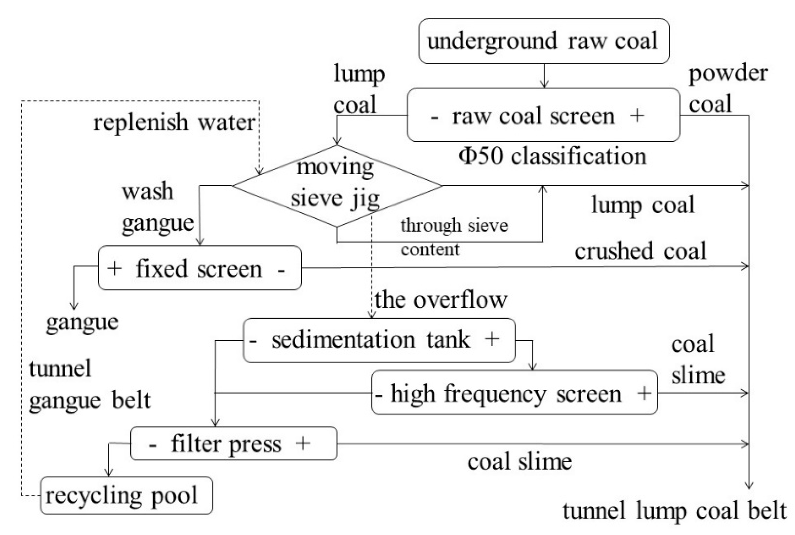
2. Process Design of an Underground Coal Primary Selection System
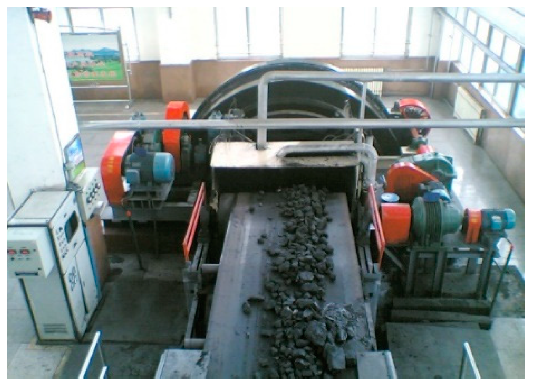
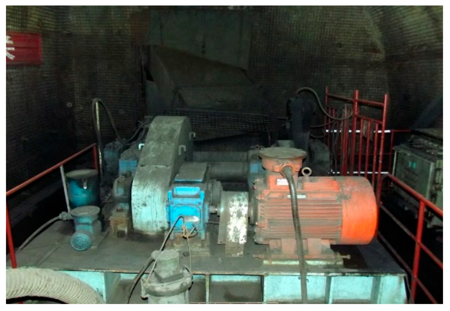
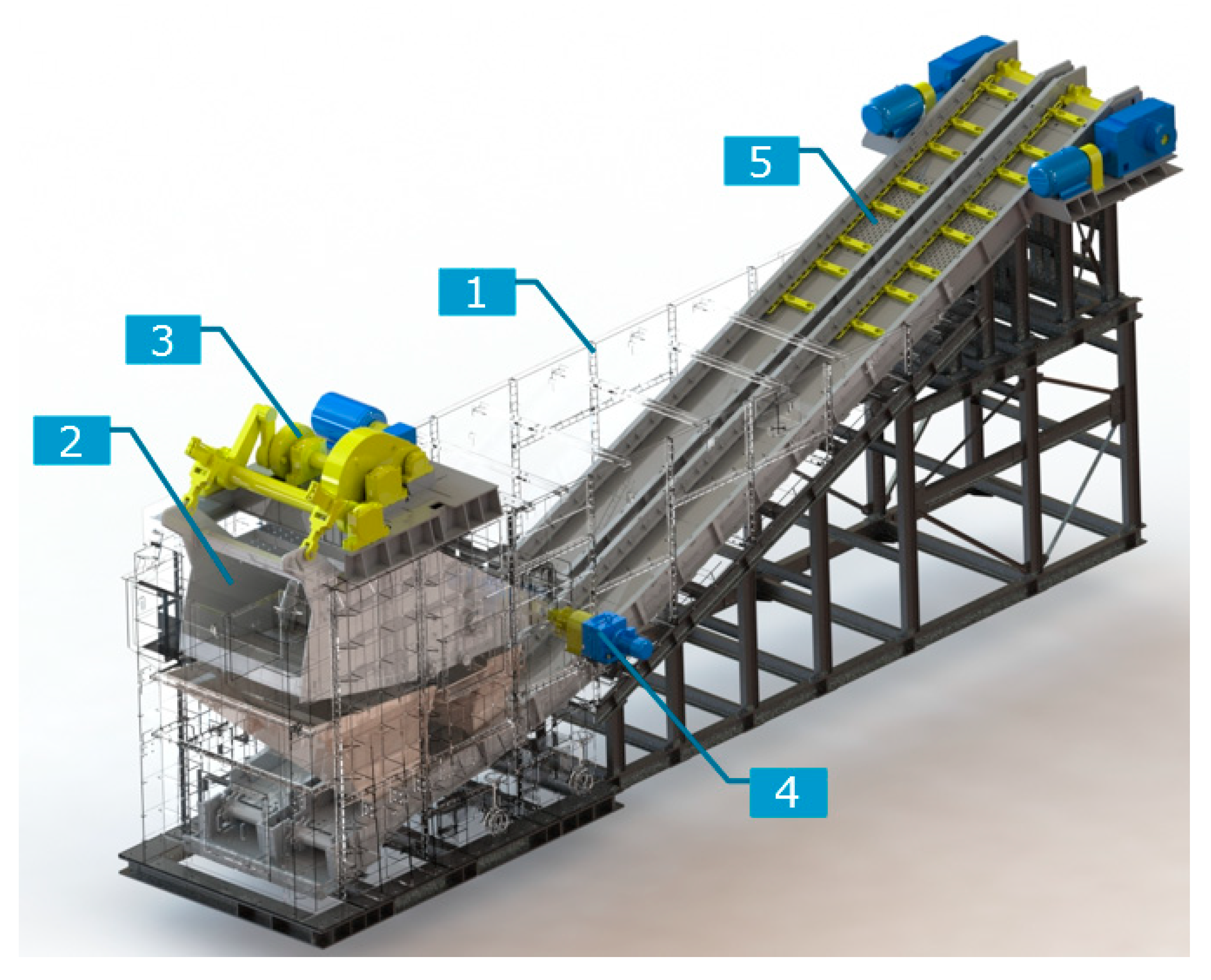
3. Innovative Design of an Underground Jigging Machine Structure
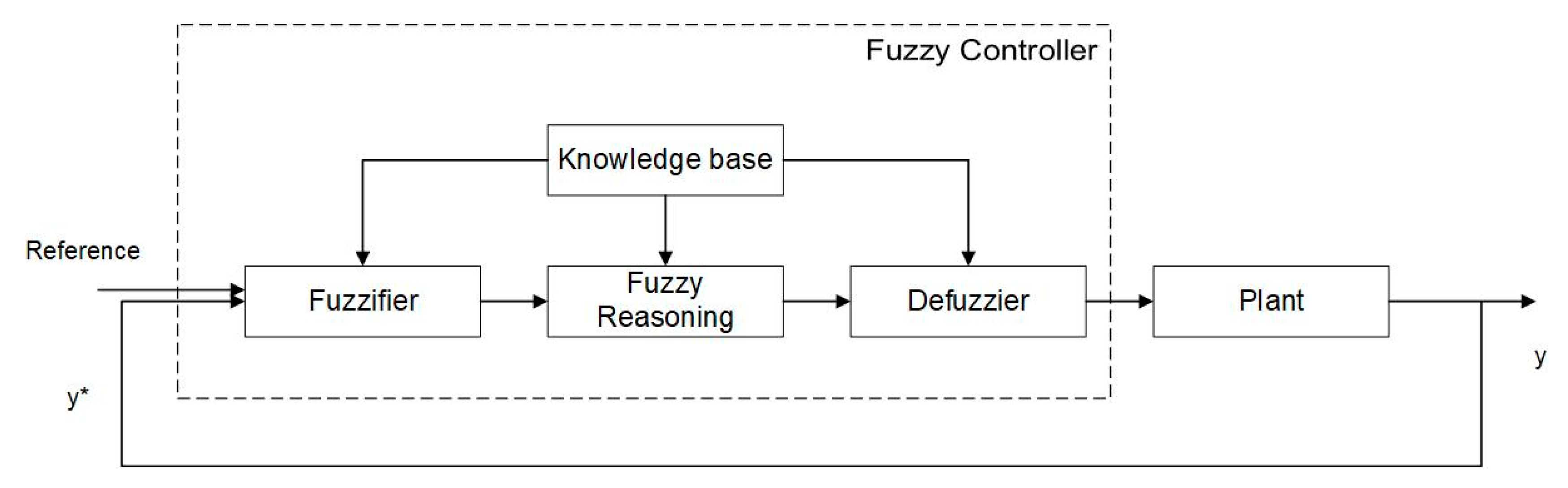
4. Fuzzy Logic Control Design of Jig
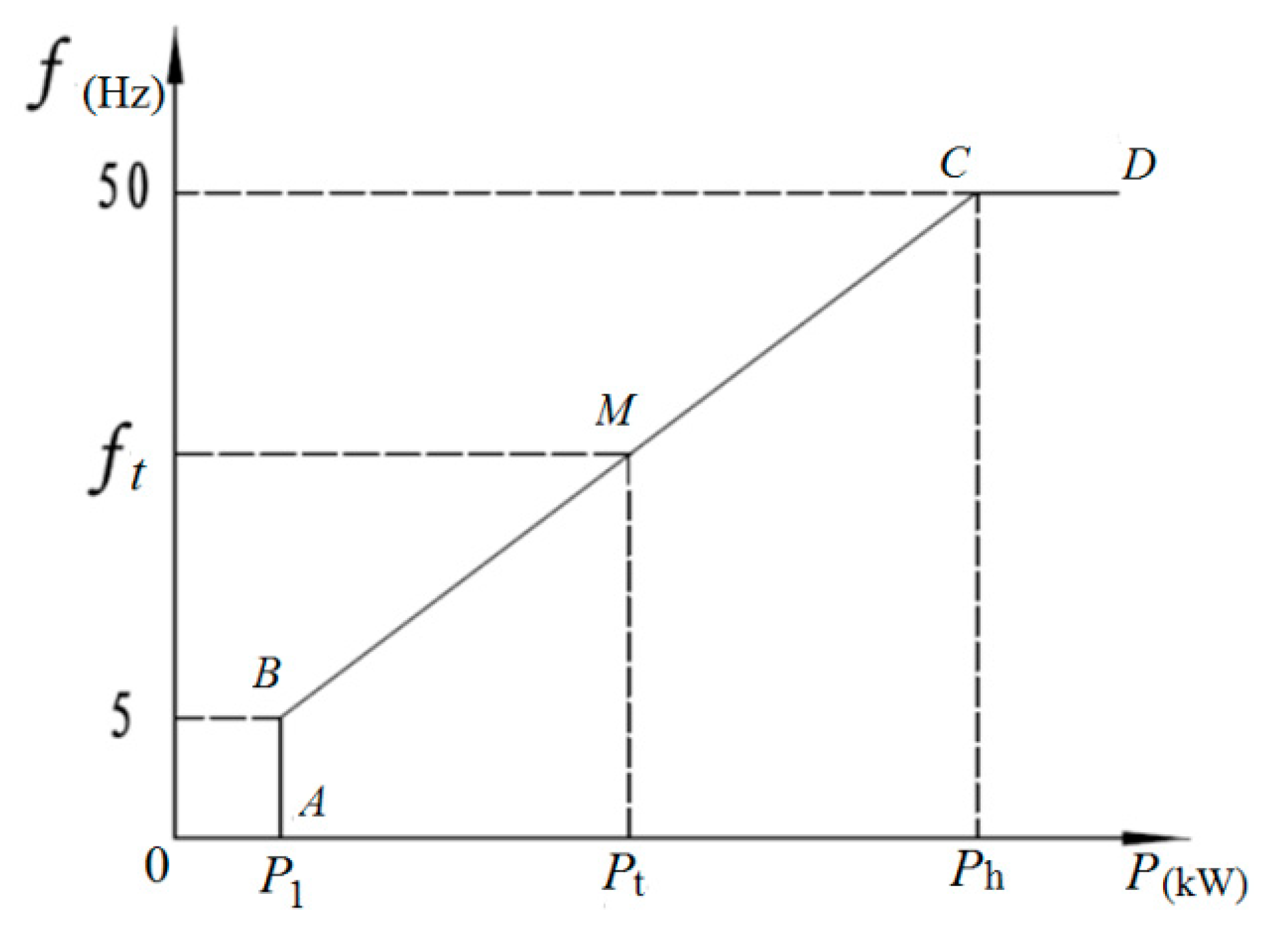
4.1. Principle of Logical Linear Control
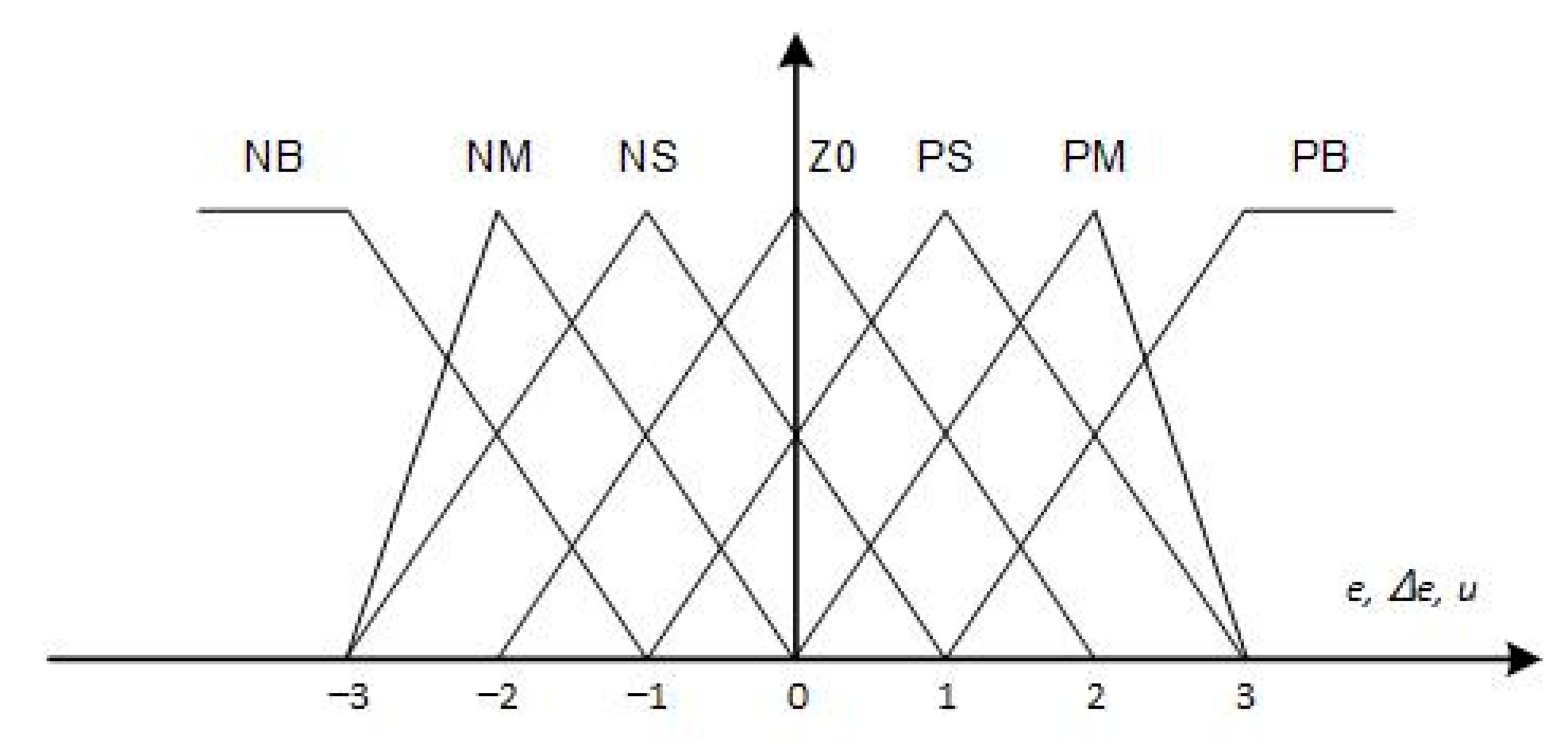
4.2. Fuzzy Control Design
4.3. Fuzzy Logic Control Output
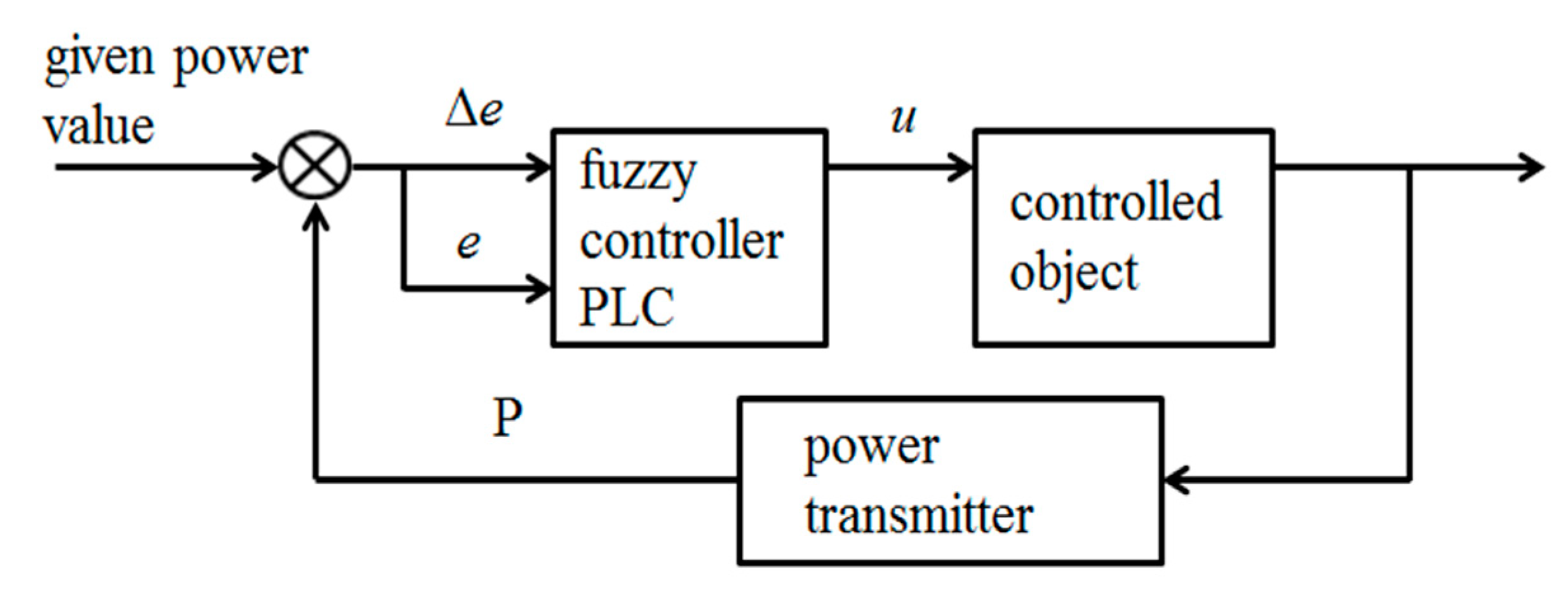
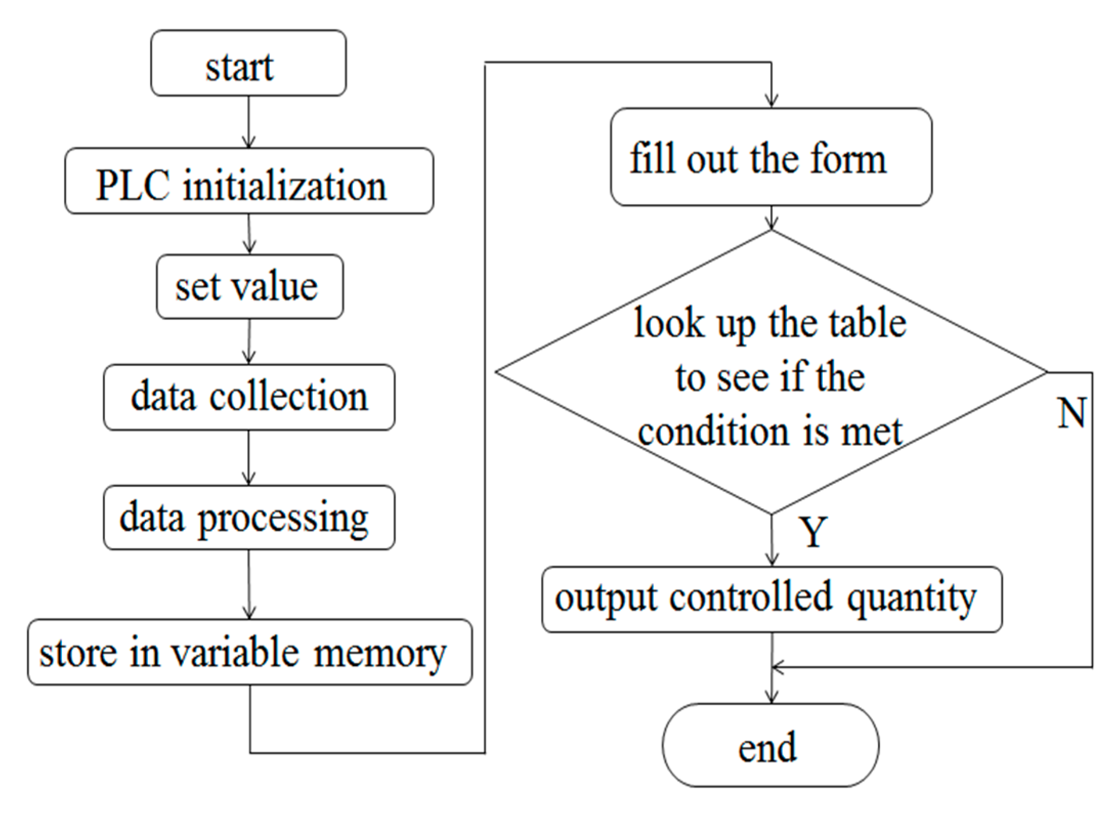
4.4. Design of the PLC Control System
5. Analysis of the Industrial Experiment and Result
6. Conclusions
Author Contributions
Funding
Conflicts of Interest
Appendix A

| Technical Term | Function |
|---|---|
| Raw coal screen | Also named roller screen, a screen grain diameter greater than 50 mm of coal and gangue |
| Moving sieve jig | Sieving coal and gangue, which is the main research object of this paper |
| Fixed screen | The last screen to separate the coal and gangue |
| Sedimentation tank | Sediments the coal slime |
| High frequency screen | Separates the coal slime and water by high frequency vibration |
| Filter press | Dehydrates the coal slime |
| Recycling pool | Provides water for the moving sieve jig |
References
- Cao, J.J.; Liu, Y.J.; Guo, G.L. The current situation in comprehensive utilization of gangue. Chin. J. Environ. Eng. 2004, 5, 19–22. [Google Scholar]
- Ma, L.Q.; Li, Y.S. The clean production technology of replacement of coal gangue in coal mine. J. China Coal Soc. 2010, 35, 816–819. [Google Scholar]
- Miao, X.X.; Zhang, J.X. Key technologies of integration of coal mining-gangue washing-backfilling and coal mining. J. China Coal Soc. 2014, 39, 1424–1433. [Google Scholar]
- Zhang, Q.; Zhang, J.X.; Wu, Z.Y. Overview of Solid Backfilling Technology Based on Coal-Waste Underground Separation in China. Sustainability 2019, 11, 2118. [Google Scholar] [CrossRef] [Green Version]
- Wang, X.M.; Zhao, B.; Zhang, C.S.; Zhang, Q.L. Paste-like self-flowing transportation backfilling technology based on coal gangue. Min. Sci. Technol. 2009, 19, 137–143. [Google Scholar] [CrossRef]
- Fu, Z.Y.; Liu, Y.M.; Liu, J. The research and application of underground coal and gangue separation technology in the field of energy conservation in Xinwen Mining area. Sci. Technol. Inf. 2011, 27, 758–808. [Google Scholar]
- Ding, K.J.; Janusz, S.L. Coal reverse flotation. Part I: Separation of a mixture of subbituminous coal and gangue minerals. Miner. Eng. 2005, 19, 72–78. [Google Scholar] [CrossRef]
- Liu, L.P.; Ren, J.J.; Liu, J. General Design of Downhole Moving Screen Discharging Gangue Machine. Coal Mine Mach. 2013, 34, 36–38. [Google Scholar]
- Zhou, J.W.; Wang, F.R.; Liu, Y.; Du, C.L. Theoretical and experimental research on ballistic separation for coal and gangue underground. J. Cent. South Univ. 2015, 46, 498–504. [Google Scholar]
- Li, J.P.; Yang, D.L.; Du, C.L. Evaluation of an Underground Separation Device of Coal and Gangue. Int. J. Coal Prep. Utili. 2013, 33, 188–193. [Google Scholar] [CrossRef]
- Zheng, K.H.; Du, C.L.; Li, J.P. Underground pneumatic separation of coal and gangue with large size (≥50 mm) in green mining based on the machine vision system. Powder Technol. 2015, 278, 223–233. [Google Scholar] [CrossRef]
- Wang, W.D.; Zhang, C. Separating coal and gangue using three-dimensional laser scanning. Int. J. Miner. Process. 2017, 169, 79–84. [Google Scholar] [CrossRef]
- Zhang, R.Z.; Fu, X.H.; Wei, L.B.; Xu, Z.Q. Fluid kinetics study on jig washer bed dilation and stratification. J. China Coal Soc. 2003, 28, 193–198. [Google Scholar]
- Mukherjee, A.K.; Dwivedi, V.K.; Mishra, B.K. Analysis of a laboratory jigging system for improved performance. Miner Eng. 2005, 18, 1037–1044. [Google Scholar] [CrossRef]
- Lv, T.T.; Ma, X.P.; Chen, L. Simulation of PID control of jig discharging system optimized by genetic algorithm. Ind. Mine Autom. 2013, 39, 67–70. [Google Scholar]
- Liu, H.S. Products separation of air pulse jig and its discharging device. Min. Process Equip. 2000, 01, 41–44. [Google Scholar]
- Kumar, S.; Venugopal, R. Performance analysis of jig for coal cleaning using 3D response surface methodology. Int. J. Min Sci. Technol. 2017, 27, 333–337. [Google Scholar] [CrossRef]
- Sanders, G.J.; Ziaja, D.; Kottmann, J. Cost-Efficient Beneficiation of Coal by ROMJIGs and BATAC Jigs. Int. J. Coal Prep. Util. 2002, 22, 395–400. [Google Scholar]
- Zhu, J.B.; Cao, Y.L.; Li, X.G.; Jia, C.L.; Chen, Q.R. Ascertainment of Index es for Jigging Separation and Its Optimum Operation by Using Artificial Neural Network. J. China Univ. Min. Technol. 1999, 2, 47–50. [Google Scholar]
- Ma, F.Q.; Ding, E.J.; Jin, L.; Tan, D.J. Intelligent Control for Jigging Process. J. China Univ. Min. Technol. 2002, 3, 80–84. [Google Scholar]
- Ni, J.J.; Sun, W.; Li, M. Research and Application of On-line Clean Ash Feedback Control System of Jigging Machine. Coal Prep. Technol. 2003, 6, 112–114. [Google Scholar]
- Yang, J.M. Intelligent Control Method of Coal Jigging Process. Master’s Thesis, Taiyuan University of Technology, Taiyuan, China, March 2004. [Google Scholar]
- Cao, W. Mechanism Optimization and Control Method Research of Moving Sieve Jig for Underground Coal Mine Raw Coal Preparation System. Master’s Thesis, China University of Mining and Technology, Beijing, China, 2019. [Google Scholar]
- Gang, F. A Survey on Analysis and Design of Model-Based Fuzzy Control Systems. IEEE Trans. Fuzzy Syst. 2006, 14, 676–697. [Google Scholar]
- King, P.J.; Mamdani, E.H. The application of fuzzy control systems to industrial processes. Automatica 1977, 13, 235–242. [Google Scholar] [CrossRef]
- Sugeno, M. An introductory survey of fuzzy control. Inf. Sci. 1985, 36, 59–83. [Google Scholar] [CrossRef]
- Bogdan, S.; Kovacic, Z. Fuzzy Controller Design: Theory and Applications; CRC/Taylor & Francis: Boca Raton, FL, USA, 2006. [Google Scholar]
- Hellendoorn, H.; Palm, R. Fuzzy system technologies at Siemens R & D. Fuzzy Set Syst. 1994, 63, 245–269. [Google Scholar]
- Radu-Emil, P.; Hans, H. A survey on industrial applications of fuzzy control. Comput. Ind. 2011, 62, 213–226. [Google Scholar]


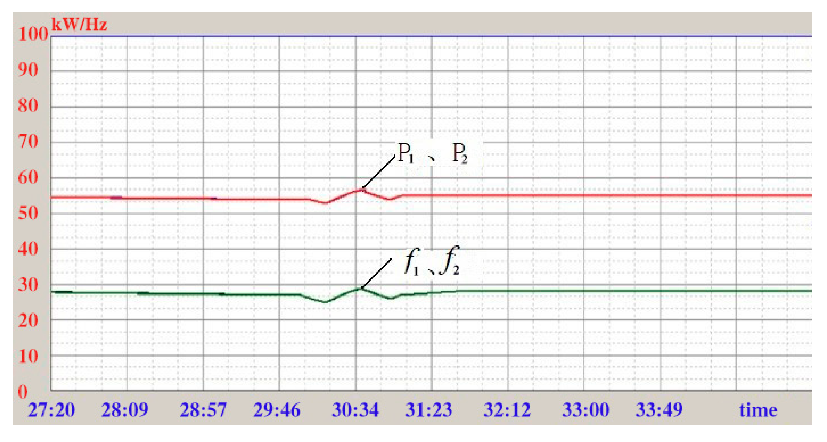
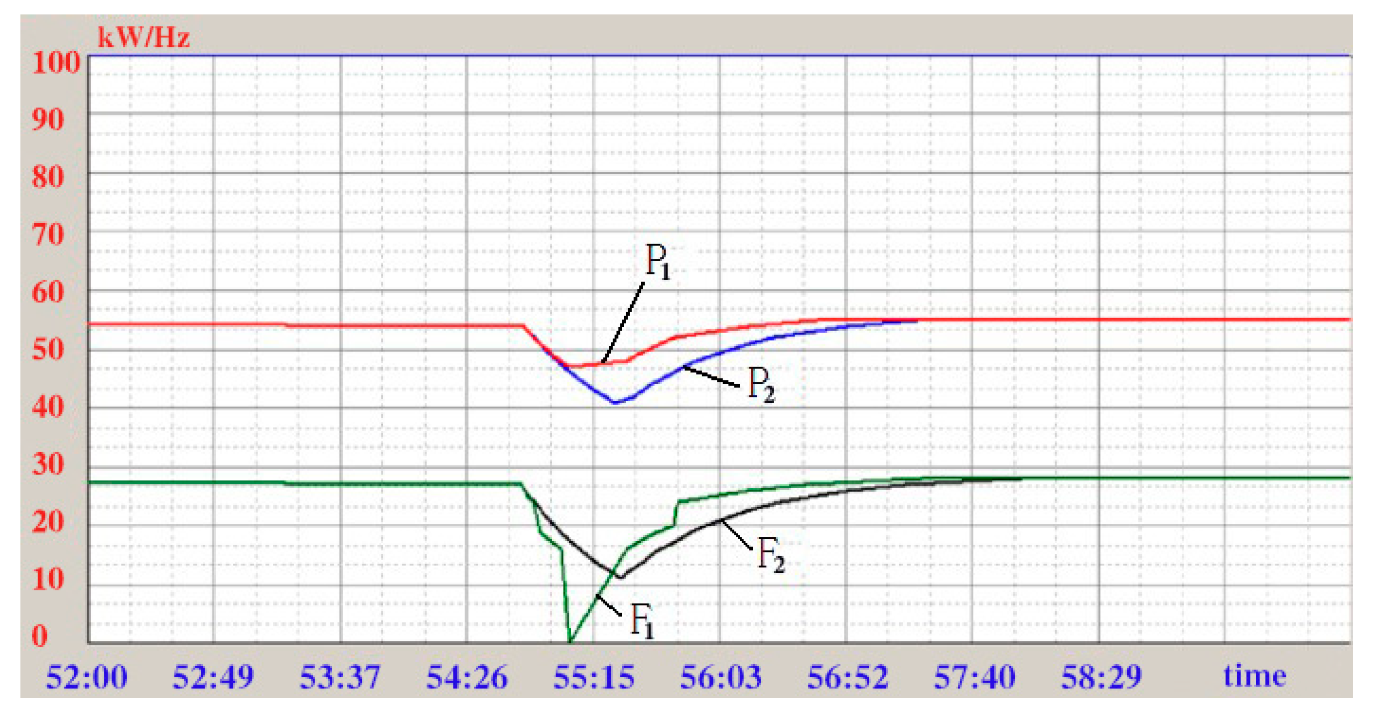
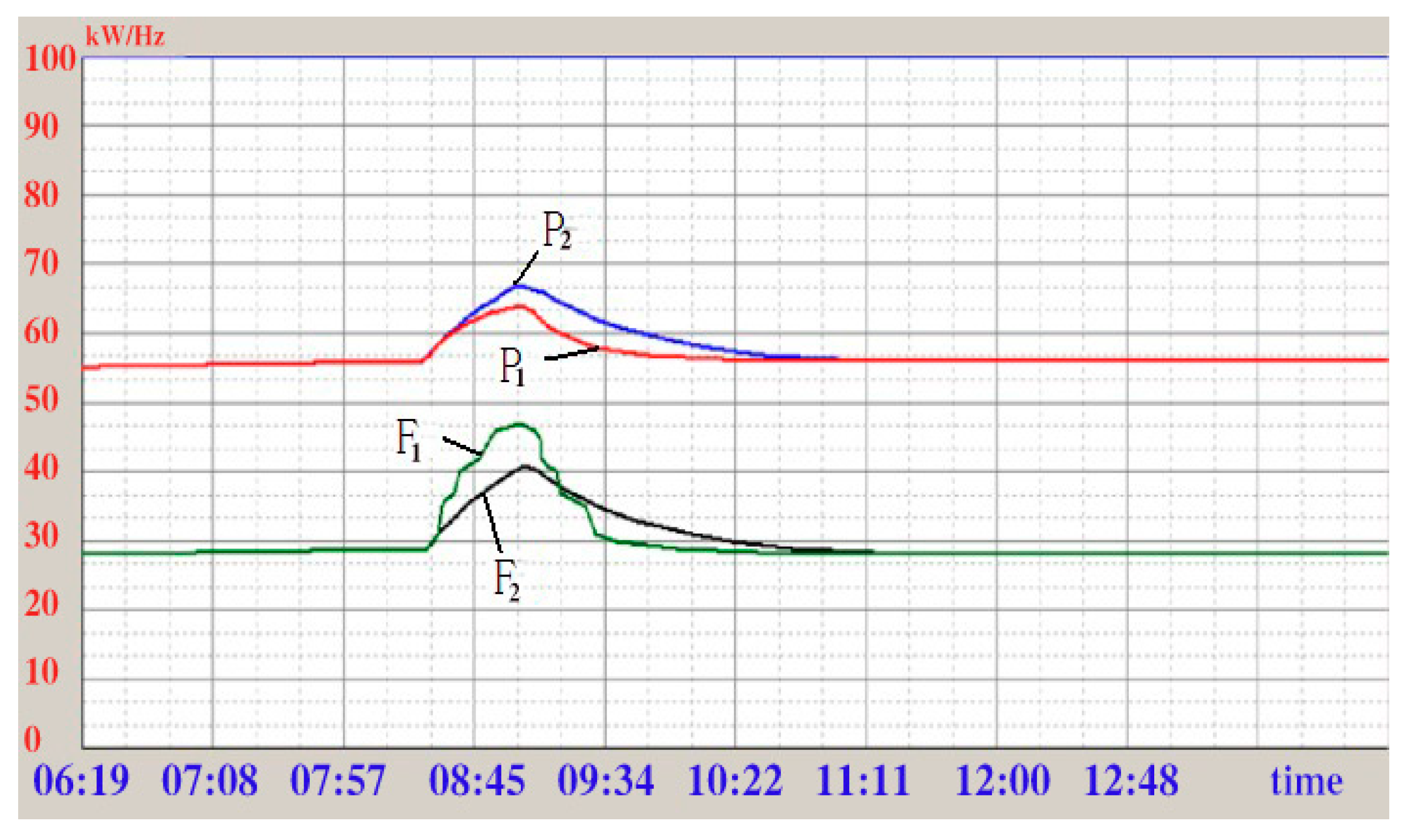
 . Power of moving sieve driving motor P1,
  . Discharge frequency f1, logical linear control:
  . Power of moving sieve driving motor P2,
  . Discharge frequency f2.
. Power of moving sieve driving motor P1, . Discharge frequency f1, logical linear control: . Power of moving sieve driving motor P2, . Discharge frequency f2.
. Discharge frequency f2.
. Power of moving sieve driving motor P1, . Discharge frequency f1, logical linear control: . Power of moving sieve driving motor P2, . Discharge frequency f2.
 . Power of moving sieve drive motor P1,
  . Discharge frequency f1, logical linear control:
  . Power of moving sieve driving motor P2,
  . Discharge frequency f2.
. Power of moving sieve drive motor P1, . Discharge frequency f1, logical linear control: . Power of moving sieve driving motor P2, . Discharge frequency f2.
. Discharge frequency f2.
. Power of moving sieve drive motor P1, . Discharge frequency f1, logical linear control: . Power of moving sieve driving motor P2, . Discharge frequency f2.
 . Power of moving sieve driving motor P1,
  . Discharge frequency f1, logical linear control:
  . Power of moving sieve driving motor P2,
  . Discharge frequency f2.
. Power of moving sieve driving motor P1, . Discharge frequency f1, logical linear control: . Power of moving sieve driving motor P2, . Discharge frequency f2.
. Discharge frequency f2.
. Power of moving sieve driving motor P1, . Discharge frequency f1, logical linear control: . Power of moving sieve driving motor P2, . Discharge frequency f2.
| Variable | e | Δe | u |
|---|---|---|---|
| Language variables | E | ΔE | U |
| Basic domain | {−20, 20} | {−3, 3} | {0.5, 1.5} |
| Fuzzy subset | NB, NM, NS, ZO, PS, PM, PB | ||
| Fuzzy domain | A = {−3, 3} | B = {−3, 3} | C = {−3, 3} |
| ΔE | NB | NM | NS | Z0 | PS | PM | PB | ||
|---|---|---|---|---|---|---|---|---|---|
| U | |||||||||
| E | |||||||||
| NB | NB | NB | NB | NB | NM | NM | NS | ||
| NM | NB | NB | NM | NM | NS | NS | Z0 | ||
| NS | NM | NM | NS | NS | Z0 | Z0 | Z0 | ||
| Z0 | NS | NS | Z0 | Z0 | Z0 | PS | PS | ||
| PS | Z0 | Z0 | Z0 | PS | PS | PM | PM | ||
| PM | Z0 | PS | PS | PM | PM | PB | PB | ||
| PB | PS | PM | PM | PB | PB | PB | PB | ||
| −3 | −2 | −1 | 0 | 1 | 2 | 3 | |
|---|---|---|---|---|---|---|---|
| NB A1, B1, C1 | 1 | 0.5 | 0 | 0 | 0 | 0 | 0 |
| NM A2, B2, C1 | 0 | 1 | 0.5 | 0 | 0 | 0 | 0 |
| NS A3, B3, C3 | 0 | 0.5 | 1 | 0.5 | 0 | 0 | 0 |
| Z0 A4, B4, C4 | 0 | 0 | 0.5 | 1 | 0.5 | 0 | 0 |
| PS A5, B5, C5 | 0 | 0 | 0 | 0.5 | 1 | 0.5 | 0 |
| PM A6, B6, C6 | 0 | 0 | 0 | 0 | 0.5 | 1 | 0 |
| PB A7, B7, C7 | 0 | 0 | 0 | 0 | 0 | 0.5 | 1 |
Publisher’s Note: MDPI stays neutral with regard to jurisdictional claims in published maps and institutional affiliations. |
© 2020 by the authors. Licensee MDPI, Basel, Switzerland. This article is an open access article distributed under the terms and conditions of the Creative Commons Attribution (CC BY) license (http://creativecommons.org/licenses/by/4.0/).
Share and Cite
Shang, D.; Yang, Z.; Wang, J.; Wang, Y.; Liu, Y. Innovative Design and Fuzzy Logic Control for An Underground Moving Sieve Jig. Mathematics 2020, 8, 2151. https://doi.org/10.3390/math8122151
Shang D, Yang Z, Wang J, Wang Y, Liu Y. Innovative Design and Fuzzy Logic Control for An Underground Moving Sieve Jig. Mathematics. 2020; 8(12):2151. https://doi.org/10.3390/math8122151
Chicago/Turabian StyleShang, Deyong, Zhiyuan Yang, Junjie Wang, Yuwei Wang, and Yue Liu. 2020. "Innovative Design and Fuzzy Logic Control for An Underground Moving Sieve Jig" Mathematics 8, no. 12: 2151. https://doi.org/10.3390/math8122151