Article

Improved Finite Element Thermomechanical Analysis of Laminated Composite and Sandwich Plates Using the New Enhanced First-Order Shear Deformation Theory

1
Missile Research Institute, Agency for Defense Development, Daejeon 34186, Republic of Korea
2
Department of Mechanical, Robotics and Energy Engineering, Dongguk University, Seoul 04620, Republic of Korea
3
Department of Mechanical System Engineering, Kumoh National Institute of Technology, Gyeongbuk 39117, Republic of Korea
4
Department of Mechanical Engineering, Incheon National University, Incheon 22012, Republic of Korea
*
Authors to whom correspondence should be addressed.
Mathematics 2024, 12(7), 963; https://doi.org/10.3390/math12070963
Submission received: 27 February 2024 / Revised: 19 March 2024 / Accepted: 22 March 2024 / Published: 24 March 2024
(This article belongs to the Topic Advances in Computational Materials Sciences)

Abstract

:
This paper proposes a simple yet accurate finite element (FE) formulation for the thermomechanical analysis of laminated composites and sandwich plates. To this end, an enhanced first-order shear deformation theory including the transverse normal effect based on the mixed variational theorem (EFSDTM_TN) was employed in the FE implementation. The primary objective of the FE formulation was to systematically interconnect the displacement and transverse stress fields using the mixed variational theorem (MVT). In the MVT, the transverse stress field is derived from the efficient higher-order plate theory including the transverse normal effect (EHOPT_TN), to enhance the solution accuracy, whereas the displacement field is defined by the first-order shear deformation theory including the transverse normal effect (FSDT_TN), to amplify the numerical efficiency. Furthermore, the transverse displacement field is modified by incorporating the components of the external temperature loading, enabling the consideration of the transverse normal strain effect without introducing additional unknown variables. Based on the predefined relationships, the proposed FE formulation can extract the C0-based computational benefits of FSDT_TN, while improving the solution accuracy for thermomechanical analysis. The numerical performance of the proposed FE formulation was demonstrated by comparing the obtained solutions with those available in the literature, including 3-D exact solutions.

1. Introduction

In recent years, the utilization of high-strength and lightweight structures has continued to improve energy efficiency in line with a wide range of environmental issues. In this regard, fiber-reinforced composite materials capable of providing an optimized stiffness-to-weight ratio through a synergistic combination of two or more materials, such as reinforcing fibers and resins, are attracting considerable attention as prospective next-generation materials in various engineering fields. Continuous fiber-reinforced composites are widely employed in various high-value industries, including automotive, civil, and aerospace, owing to their ability to achieve excellent structural properties and multifunctional characteristics. Despite the aforementioned advantages, the distribution of transverse stress in laminated composite structures can give rise to inherent mechanical defects, notably layer slip and delamination. Therefore, accurate prediction of transverse stress is a crucial concern in the structural design process of laminated composite structures [1,2].
Over the past half-century, a range of analysis models based on the equivalent single-layer theory have been developed to precisely elucidate the transverse behaviors of laminated composite plates [3,4,5,6,7,8,9,10,11,12,13,14,15,16,17,18,19,20,21,22,23,24,25,26,27,28]. Starting from the well-known classical laminated plate theory (CLPT) and progressing through the first-order shear deformation theory (FSDT), a series of higher-order polynomial theories, including the higher-order shear deformation theory (HSDT), have been developed sequentially [3,4,5,6,7,8]. However, most of these theories exhibit limitations in predicting interlaminar stresses because of their inability to enforce transverse shear stress conditions at both the surface and layer interfaces. To address this issue, a series of refined zigzag theories (EHOPT: efficient higher order plate theory, RHSDT: refined higher-order shear deformation theory, RZT: refined zigzag theory) have been proposed [14,15,16,17,18]. These theories yield reliable results in predicting the global and local behaviors of laminated composites and sandwich structures by introducing a zigzag displacement field that varies discontinuously at the interlaminar interfaces. However, it requires the use of a nonconventional C1-class shape function (a slope continuity condition along the boundary of the element) in the finite element (FE) formulation, which is incompatible with commercial FE software such as ANSYS 2023 R1 (Ansys, PA, USA) and ABAQUS 2022 (Dassault Systemes, Pairs, France). As an attractive scheme to circumvent C1-class problems in FE analysis, enhanced analysis models (EFSDT: enhanced first-order shear deformation theory, EFSDTM: enhanced first-order shear deformation theory based on mixed variational theorem) were developed for the multiphysics analysis of laminated composites and sandwich plates [19,20,21]. Enhanced theories can simultaneously improve the solution accuracy and computational efficiency by systematically deriving reasonable energy relationships between the conventional FSDT and EHOPT. Consequently, these theories allow for a C0-based finite element formulation based on an FSDT-like governing equation, providing clear advantages in terms of compatibility with commercial finite element (FE) software (ANSYS 2023 R1 and ABAQUS 2022).
With technological advancements, laminated composites and sandwich structures can be exposed to various external environments, and there is a need to predict their multi-physical behaviors during the design process. In high-temperature environments, thermal deformation and stress induce significant defects. Consequently, thermomechanical analysis should be considered to ensure reliable design solutions for laminated composites and sandwich structures exposed to such conditions. Transverse normal deformation is a very important consideration in thermal analysis. Therefore, well-known analysis models (CLPT, FSDT, HSDT, EHOPT, etc.) that ignore the transverse normal strain effect are not suitable for predicting the thermal behavior of laminated composites and sandwich structures. In this regard, many refined theories have been proposed to precisely describe the thermomechanical responses of laminated composites and sandwich structures [29,30,31,32,33,34,35,36,37,38,39,40,41,42,43,44,45,46,47,48,49,50,51,52,53,54,55,56]. As a higher-order polynomial model, the Lo–Christensen–Wu (LCW) theory attempts to consider the transverse normal strain effect effectively by assuming a smooth parabolic form of the transverse displacement field [29]. Furthermore, various refined higher-order and zigzag theories have been proposed for the thermomechanical analysis of laminated composites and sandwich structures [29,30,31,32,33,34,35,36,37,38,39,40,41,42,43,44,45,46,47,48]. As one of the most attractive zigzag theories, the efficient higher-order zigzag theory (EHOZT) proposed by Oh and Cho can provide reliable solutions for fully coupled electro-thermo-mechanical problems by enforcing transverse shear stress conditions at both the surface and layer interfaces [40,41,42,43]. Kapuria and Achary developed a computationally efficient zigzag theory to predict the thermal behavior of laminated composite structures [44]. Although this theory considers the transverse normal strain effect without introducing additional variables into the displacement fields, its applicability in analyzing sandwich plates is limited. This is because the use of different thermal expansion coefficients in adjacent layers can potentially violate the transverse displacement continuity conditions. Among the various enhanced theories for the thermomechanical analysis of laminated composites and sandwich structures [49,50,51], Han et al. proposed an enhanced first-order shear deformation theory including the transverse normal strain effect based on the mixed variational theorem (EFSDTM_TN) to take computational benefits of conventional FSDT [50]. The main contribution of EFSDTM_TN is that it considers the transverse normal strain effect without introducing any additional unknown variables by extending the transverse normal displacement field under the prescribed thermal conditions. Furthermore, the transverse displacement continuity conditions are automatically satisfied in the sandwich plates by introducing layer-wise constants. Consequently, EFSDTM_TN can provide reliable solutions for analyzing the thermomechanical behaviors of laminated composite and sandwich structures while ensuring the computational benefits of the C0-based 5-DOF element in the FE implementation.
To further extend the applicability of the EFSDTM_TN [50], an FE formulation based on the EFSDTM_TN was proposed and numerically tested. An 8-node serendipity element was utilized in the FE formulation to enhance the computational efficiency in deriving the stress distributions. The primary objective of the proposed FE analysis model is to ensure both the solution accuracy and computational efficiency by systematically blending FSDT_TN and EHOPT_TN based on the mixed variational theorem. Furthermore, the thermal responses of laminated composites and sandwich structures can be described more precisely by improving the transverse displacement field. To demonstrate the numerical performance of the proposed FE analysis model, representative thermal-mechanical problems for 2-D laminated composite and sandwich structures were considered as numerical examples. The accuracy and efficiency of the proposed FE analysis model were compared with other numerical results available in the literature, including 3-D exact solutions [57,58] together with the analytical solution of the EFSDTM_TN [50].

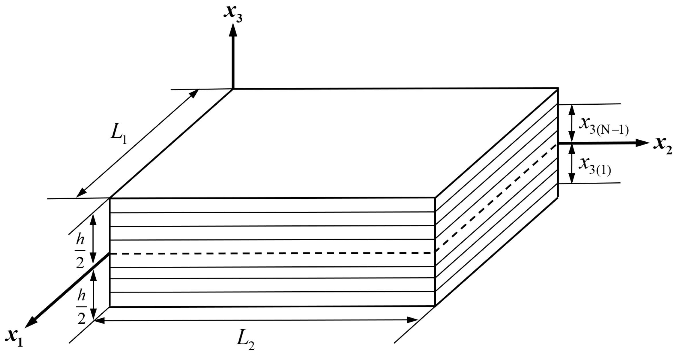
2. EFSDTM_TN for the Thermo-Mechanical Problem

2.1. Mixed Variational Theorem

Laminated composites and sandwich plates were considered as numerical models of thermomechanical problems. The geometric shapes and reference coordinates of the laminated plates are shown in Figure 1. Unless otherwise specified in the tensor notation, the Greek indices use values from set {1, 2}, whereas the Latin indices are assigned values from set {1, 2, 3}. L α and h represent the in-plane length and thickness of the laminated plates, respectively. x 3 denotes the transverse position which takes values within the range [ h / 2 , h / 2 ].
In the EFSDTM_TN, displacement and transverse stress fields are assumed independently, with the aim of enhancing both solution accuracy and computational efficiency. These independent fields can then be systematically interconnected based on the mixed variational theorem (MVT). The first variation of the 2-D Hellinger–Reissner functional is defined by Equation (1).
δ Π R 2 D = Ω σ ¯ α β 2 D δ ε ¯ α β + σ α 3 * δ γ ¯ 3 α + ( γ ¯ 3 α γ 3 α * ) δ σ 3 α * d Ω S σ p ˜ i δ u ¯ i d S σ = 0
where
· = h / 2 h / 2 · d x 3 ,   ε ¯ γ ω = 1 2 ( u ¯ γ , ω + u ¯ ω , γ )   ,   γ ¯ 3 α = u ¯ α , 3 + u ¯ 3 , α ,   γ 3 α * = C 3 α 3 β 1 σ 3 β *
In Equation (1), Ω represents the reference plane of the laminated plates, and mechanical loading ( p ˜ i ) is applied to the boundary area ( S σ ). Additionally, · ¯ and · * are components defined by the displacement and transverse stress fields, respectively. The mixed part of the MVT plays a critical role in defining reasonable relationships between two independent fields [20,50,51].

2.2. Improvement of Transverse Displacement Field

In contrast to the mechanical behavior, the transverse normal strain effect is dominant in the thermal deformation of the laminated composite and sandwich plates. Therefore, this effect should be considered to provide a reliable solution for predicting thermal behavior. Intuitively, assuming a smoothly varying parabolic form for the transverse displacement field can help in this regard. Although this approach is able to predict the thermal behavior of laminated composites and sandwich plates precisely, it involves additional unknown variables as well as complicated 3-D governing equations. Therefore, to provide simple yet accurate solutions for thermal problems, a modified transverse displacement field is introduced as follows [50].
u 3 = u 3 ( 0 ) + φ ( k ) T 0 x 3 + 1 2 T 1 x 3 2 + k = 1 N 1 S 3 ( k ) H ( x 3 x 3 ( k ) ) ¯
The underlined expressions are newly considered in Equation (3) for a reliable thermal analysis of the laminated composites and sandwich plates. Other than the underlined expressions, this represents a typical transverse displacement field that satisfies the assumption of a plane-stress state ( u 3 u 3 ( 0 ) ). Based on Equation (3), the prescribed thermal conditions ( T 0 and T 1 ) are utilized to define a smoothly varying parabolic field to consider the transverse normal strain effect without introducing additional unknown variables. Here, N represents the total number of layers and H ( x 3 x 3 ( k ) ) is the Heaviside step function. T 0 and T 1 are the uniform and linear temperature loadings, respectively. In addition, φ ( k ) is a layer-wise constant that automatically satisfies the plane-stress condition. The value of φ ( k ) can vary depending on the material composing each layer because it is a function of the material properties and thermal expansion coefficients. Therefore, to fulfill the continuity conditions of u 3 for general layup cases such as sandwich plates, a layer-wise constant ( S 3 ( k ) ) was additionally introduced. This modified form of the transverse displacement field enables simple yet accurate thermomechanical analysis of laminated composites and sandwich plates.

2.3. Transverse Stress Field

In this subsection, a reliable transverse stress field based on EHOPT_TN is independently assumed in the MVT to ensure solution accuracy. EHOPT_TN can rigorously satisfy the shear-free conditions at the surface, as well as shear continuity conditions at the layer interfaces by introducing third-order zigzag field in the in-plane displacement field. Furthermore, a modified form of the transverse displacement field was employed to provide reliable solutions to thermomechanical problems. The initial displacement field of EHOPT_TN is expressed as [50]
u α * = u α * ( 0 ) + u α * ( 1 ) x 3 + u α * ( 2 ) x 3 2 + u α * ( 3 ) x 3 3 + k = 1 N 1 S α ( k ) ( x 3 x 3 ( k ) ) H ( x 3 x 3 ( k ) ) , u 3 * = u 3 * ( 0 ) + φ ( k ) T 0 x 3 + 1 2 T 1 x 3 2 + k = 1 N 1 S 3 ( k ) H ( x 3 x 3 ( k ) )
where S α ( k ) is a linear zigzag field that enforces shear continuity conditions at the layer interfaces. By applying the shear stress conditions to the initial displacement field given in Equation (4), S α ( k ) and S 3 ( k ) can be defined through relations in terms of the primary unknown variables ( u i * ( k ) ) and prescribed thermal conditions ( T 0 ,   T 1 ):
S α ( k ) = a α β ( k ) u β * ( 3 ) + b α β ( k ) T 0 , β + c α β ( k ) 1 2 T 1 , β ,   S 3 ( k ) = b 33 ( k ) T 0 + c 33 ( k ) 1 2 T 1
Detailed definitions of a α β ( k ) ,   b α β ( k ) ,   c α β ( k ) and b 33 ( k ) ,   c 33 ( k ) are provided in [50].
Furthermore, to satisfy the plate equilibrium state rigorously when applying MVT to the general configuration of laminated structures, in-plane correction factors were introduced in EHOPT_TN. Consequently, Equations (4) and (5) yield the following refined displacement field for EHOPT_TN [50]:
u α * = u α * ( 0 ) u 3 , α * ( 0 ) x 3 +   Φ α β ( 1 ) u β * ( 3 ) +   Φ α β ( 2 ) T 0 , β +   Φ α β ( 3 ) 1 2 T 1 , β C α N C α M x 3 , u 3 * = u 3 * ( 0 ) + φ ( k ) x 3 + k = 1 N 1 b 33 ( k ) H ( x 3 x 3 ( k ) ) T 0 + φ ( k ) x 3 2 + k = 1 N 1 c 33 ( k ) H ( x 3 x 3 ( k ) ) 1 2 T 1
where
Φ α β ( 1 ) = x 3 3 3 h 2 4 x 3 δ α β + k = 1 N 1 a α β ( k ) f x 3 ,   x 3 ( k ) , Φ α β ( 2 ) = h 2 φ ( N ) φ ( 1 ) 2 x 3 + φ ( N ) + φ ( 1 ) h x 3 2 2 δ α β + k = 1 N 1 b α β ( k ) f x 3 ,   x 3 ( k ) + k = 1 N 1 b 33 ( k ) x 3 2 x 3 2 2 h δ α β , Φ α β ( 3 ) = h 2 4 φ ( N ) + φ ( 1 ) 2 x 3 + φ ( N ) φ ( 1 ) h x 3 2 2 δ α β + k = 1 N 1 c α β ( k ) f x 3 ,   x 3 ( k ) + k = 1 N 1 c 33 ( k ) x 3 2 x 3 2 2 h δ α β
in which
f x 3 ,   x 3 ( k ) = x 3 2 x 3 2 2 h + ( x 3 x 3 ( k ) ) H ( x 3 x 3 ( k ) )
where δ α β is the Kronecker delta function and the in-plane correction factor C α N ,   C α M can be defined as
C α N = c α β N ( u * ) u β * ( 3 ) + c α β N ( T o ) T o , β + c α β N ( T 1 ) 1 2 T 1 , β ,   C α M = c α β M ( u * ) u β * ( 3 ) + c α β M ( T o ) T o , β + c α β M ( T 1 ) 1 2 T 1 , β
c α β N , M ( u * ) ,   c α β N , M ( T 0 ) , and c α β N , M ( T 1 ) can be determined by matching the resulting forces and moments in the process of establishing a relationship between the displacement and transverse stress fields based on Saint-Venant’s principle [50]. Based on the introduction of these in-plane correction factors, it is possible to provide highly reliable solutions for predicting the thermomechanical behavior of laminated composites and sandwich plates.
From Equation (6), the transverse stress tensors used in the MVT can be defined as follows:
γ β 3 * = Φ β γ , 3 ( 1 ) u γ * ( 3 ) + Φ β γ , 3 ( 2 ) T o , γ + Φ β γ , 3 ( 3 ) 1 2 T 1 , γ C β M , σ α 3 * = C α 3 β 3 γ β 3 *   = C α 3 β 3 Φ β γ , 3 ( 1 ) u γ * ( 3 ) + Φ β γ , 3 ( 2 ) T o , γ + Φ β γ , 3 ( 3 ) 1 2 T 1 , γ C β M  

2.4. Displacement Field

Simple displacement field based on FSDT_TN were also considered in MVT to retain computational efficiency [50]. The displacement field based on FSDT_TN is given as
u ¯ α = u ¯ α ( 0 ) + u ¯ α ( 1 ) x 3 , u ¯ 3 = u ¯ 3 ( 0 ) + φ ( k ) T 0 x 3 + 1 2 T 1 x 3 2 + k = 1 N 1 S 3 ( k ) H ( x 3 x 3 ( k ) )
where the components of FSDT_TN are indicated by overbars to clearly distinguish between the displacement and transverse stress fields in MVT. From Equation (11), the strain and in-plane stress tensors used in the MVT can be derived as
ε ¯ α β = ε ¯ α β ( 0 ) + ε ¯ α β ( 1 ) x 3 , γ ¯ 3 α = γ ¯ 3 α ( 0 ) + φ ( k ) x 3 + k = 1 N 1 b 33 ( k ) H ( x 3 x 3 ( k ) ) T 0 , α + φ ( k ) x 3 2 + k = 1 N 1 c 33 ( k ) H ( x 3 x 3 ( k ) ) 1 2 T 1 , α , σ ¯ α β = Q α β γ ω ( ε ¯ γ ω α γ ω Δ T )
where α γ ω and Δ T are the thermal expansion coefficient and temperature distribution.

2.5. Relationships between Displacement and Transverse Stress Fields

A reasonable relationship between EHOPT_TN and FSDT_TN can be systematically defined using the mixed part in the MVT as a constraint equation. The related constraint equation is expressed as the following [50]:
Ω ( γ ¯ 3 α γ 3 α * ) δ σ 3 α * d Ω = 0
where γ 3 α * and σ 3 α * are defined in Equation (10), while γ ¯ 3 α is defined in Equation (12). In the constraint equation, the transverse shear resultant ( Q α * ) derived from EHOPT_TN can be expressed as
Q α * = σ 3 α * = A ^ α 3 β 3 ( 0 ) u β * ( 3 ) + A ^ α 3 β 3 ( 1 ) T 0 , β + A ^ α 3 β 3 ( 2 ) 1 2 T 1 , β
in which
A ^ α 3 β 3 ( 0 ) = C α 3 γ 3 Φ γ β , 3 ( 1 ) c γ β M ( u * ) , A ^ α 3 β 3 ( 1 ) = C α 3 γ 3 Φ γ β , 3 ( 2 ) c γ β M ( T o ) , A ^ α 3 β 3 ( 2 ) = C α 3 γ 3 Φ γ β , 3 ( 3 ) c γ β M ( T 1 )
Equations (13)–(15) yield the relationships between u α * ( 3 ) and γ ¯ 3 α ( 0 ) as follows:
u β * ( 3 ) = Γ β α ( 1 ) γ ¯ α 3 ( 0 ) + Γ β α ( 2 ) T o , α + Γ β α ( 3 ) 1 2 T 1 , α
where
Γ β α ( 1 ) = A ˜ β 3 γ 3 ( 0 ) 1 A ^ γ 3 α 3 ( 0 ) , Γ β α ( 2 ) = A ˜ β 3 γ 3 ( 0 ) 1 B ^ γ 3 α 3 ( 0 ) A ˜ γ 3 α 3 ( 1 ) , Γ β α ( 3 ) = A ˜ β 3 γ 3 ( 0 ) 1 D ^ γ 3 α 3 ( 0 ) A ˜ γ 3 α 3 ( 2 )
in which
A ˜ γ 3 β 3 ( 0 ) = Φ γ α , 3 ( 1 ) c γ α M ( u * ) C α 3 μ 3 Φ μ β , 3 ( 1 ) c μ β M ( u * ) , A ˜ γ 3 β 3 ( 1 ) = Φ γ α , 3 ( 1 ) c γ α M ( u * ) C α 3 μ 3 Φ μ β , 3 ( 2 ) c μ β M ( T 0 ) , A ˜ γ 3 β 3 ( 2 ) = Φ γ α , 3 ( 1 ) c γ α M ( u * ) C α 3 μ 3 Φ μ β , 3 ( 3 ) c μ β M ( T 1 ) , B ^ γ 3 β 3 ( 0 ) = Φ γ α , 3 ( 1 ) c γ α M ( u * ) C α 3 β 3 φ ( k ) x 3 + k = 1 N 1 b 33 ( k ) H ( x 3 x 3 ( k ) ) , D ^ γ 3 β 3 ( 0 ) = Φ γ α , 3 ( 1 ) c γ α M ( u * ) C α 3 β 3 φ ( k ) x 3 2 + k = 1 N 1 c 33 ( k ) H ( x 3 x 3 ( k ) )
Consequently, the transverse shear resultant ( Q α * ) can be expressed in terms of the FSDT_TN variables by substituting Equation (16) into Equation (14) as follows:
Q α * = A α 3 β 3 * γ ¯ β 3 ( 0 ) + B α 3 β 3 * T o , β + D α 3 β 3 * 1 2 T 1 , β
where
A α 3 β 3 * = A ^ α 3 μ 3 ( 0 ) A ˜ μ 3 γ 3 ( 0 ) 1 A ^ γ 3 β 3 ( 0 )   , B α 3 β 3 * = A ^ α 3 μ 3 ( 0 ) A ˜ μ 3 γ 3 ( 0 ) 1 B ^ γ 3 β 3 ( 0 ) A ˜ γ 3 β 3 ( 1 ) + A ^ α 3 β 3 ( 1 ) , D α 3 β 3 * = A ^ α 3 μ 3 ( 0 ) A ˜ μ 3 γ 3 ( 0 ) 1 D ^ γ 3 β 3 ( 0 ) A ˜ γ 3 β 3 ( 2 ) + A ^ α 3 β 3 ( 2 )
A α 3 β 3 * ,   B α 3 β 3 * and D α 3 β 3 * are the effective shear stiffness moduli, which depend on the in-plane correction factors. Thus, these in-plane correction factors and effective shear stiffness moduli should be updated by applying iterative calculations to improve the solution accuracy. Equation (20) indicates that the effective shear correction factor (SCF) can be calibrated automatically using EFSDTM_TN [50].
Based on the reasonable relationship between EHOPT_TN and FSDT_TN, the 2-D Hellinger–Reissner functional can be simplified as
δ Π R 2 D Ω σ ¯ α β 2 D δ ε ¯ α β + σ α 3 * δ γ ¯ 3 α d Ω S σ p ˜ i δ u ¯ i d S σ = 0
Therefore, considering transverse loading ( t ˜ 3 ), the governing equations of EFSDTM_TN can be derived as
δ u ¯ α ( 0 )   :   N ¯ α β , β = 0 , δ u ¯ α ( 1 )   :   M ¯ α β , β Q α * = 0 , δ u ¯ 3 ( 0 )   :   Q α , a * =   p ˜ 3
and the associated boundary conditions are given by
δ u ¯ α ( 0 ) = 0 o r N ¯ α β v β = 0 , δ u ¯ α ( 1 )   = 0 o r M ¯ α β v β = 0 , δ u ¯ 3 ( 0 )   = 0 o r Q α * v α =   0
It should be noted that the governing equations of EFSDTM_TN are similar to those of conventional FSDT. This implies that the EFSDTM_TN can be extended using a simple FE implementation.
Once the values of all of the unknown variables are determined based on the governing equation, the solution accuracy can be further improved by restoring the displacement field of EHOPT_TN. By applying the least-squares approximation, the following relationships between u α * ( 0 ) and u ¯ α ( 0 ) are obtained [50]:
u α * ( 0 ) = u ¯ α ( 0 ) 1 h Φ α β ( 1 ) u β * ( 3 ) 1 h Φ α β ( 2 ) T 0 , β 1 h Φ α β ( 2 ) 1 2 T 1 , β
Substituting Equations (16) and (24) into Equation (6), the displacement field of EHOPT_TN can be systematically expressed using only the primary variables of FSDT_TN as follows:
u α * = u ¯ α ( 0 ) u ¯ 3 , α ( 0 ) x 3 +   Φ ˜ α β ( 1 ) Γ β γ ( 1 ) γ ¯ γ 3 ( 0 ) +   Φ ˜ α β ( 1 ) Γ β γ ( 2 ) + Φ ˜ α γ ( 2 ) T 0 , γ   +   Φ ˜ α β ( 1 ) Γ β γ ( 3 ) + Φ ˜ α γ ( 3 ) 1 2 T 1 , γ C α N C α M x 3 , u 3 * = u ¯ 3 ( 0 ) + φ ( k ) T 0 x 3 + 1 2 T 1 x 3 2 + k = 1 N 1 S 3 ( k ) H ( x 3 x 3 ( k ) )
in which
Φ ˜ α β ( i ) = Φ α β ( i ) 1 h Φ α β ( i )

3. Finite Element Formulation Based on EFSDTM_TN

In this section, a finite element formulation based on EFSDTM_TN is presented to further extend its applicability. Considering the stress restoration based on the post-processing procedure, a well-known 8-node serendipity element was employed in the FE implementation. Based on the FE discretization, the displacement field can be defined by the nodal variables of the 8-node serendipity element as follows [21]:
u ¯ α ( 0 ) = i = 1 8 N i u ¯ α i ( 0 ) ,   u ¯ α ( 1 ) = i = 1 8 N i u ¯ α i ( 1 ) ,   u ¯ 3 ( 0 ) = i = 1 8 N i u ¯ 3 i ( 0 )
where N i represents the shape function for the (i)th node of the 8-node serendipity element.

3.1. Element Stiffness Matrix

The element stiffness matrix can be defined through the principle of minimum potential energy, and all unknown nodal displacements in each 8-node serendipity element can be expressed in vector form as follows [21]:
d ¯ e = d ¯ 1 d ¯ 2 d ¯ 3 d ¯ 4 d ¯ 5 d ¯ 6 d ¯ 7 d ¯ 8 T
in which
d ¯ i = u ¯ 1 i ( 0 ) u ¯ 2 i ( 0 ) u ¯ 3 i ( 0 ) u ¯ 1 i ( 1 ) u ¯ 2 i ( 1 ) T
As indicated in Equation (28), each element has 40 degrees of freedom (DOF).
From Equations (27)–(29) and the assumption of small strain-displacement relations, the strain components for each element are defined as
ε ¯ m e = u ¯ 1 , 1 ( 0 ) u ¯ 2 , 2 ( 0 ) u ¯ 1 , 2 ( 0 ) + u ¯ 2 , 1 ( 0 ) e = B m d ¯ e ,   ε ¯ b e = u ¯ 1 , 1 ( 1 ) u ¯ 2 , 2 ( 1 ) u ¯ 1 , 2 ( 1 ) + u ¯ 2 , 1 ( 1 ) e = B b d ¯ e ,   ε ¯ s e = u ¯ 3 , 1 ( 0 ) + u ¯ 1 ( 1 ) u ¯ 3 , 2 ( 0 ) + u ¯ 2 ( 1 ) e = B s d ¯ e
where the subscripts (m, b and s) denote the strain components derived from the membrane, bending, and transverse shear parts, respectively. The strain matrices ( B m ,   B b , and B s ) can be written as follows:
B ( m , b , s ) = B ( m , b , s ) 1 B ( m , b , s ) 2 B ( m , b , s ) 7 B ( m , b , s ) 8
in which
B ( m ) i = N i , x 0 0 0 0 0 N i , y 0 0 0 N i , y N i , x 0 0 0 , B ( b ) i = 0 0 0 N i , x 0 0 0 0 0 N i , y 0 0 0 N i , y N i , x , B ( s ) i = 0 0 N i , x N i 0 0 0 N i , y 0 N i
The element stiffness matrix is then reasonably defined by using the aforementioned strain matrices B ( m , b , s ) :
K e = K m + 2 K m b + K b + K s
in which
K m = A B m T A ¯ B m d A ,   K m b = A B m T B ¯ B b d A , K b = A B b T D ¯ B b d A ,   K s   = A B s T G * ( 0 ) B s d A
In Equation (34), A ¯ ,   B ¯ ,   D ¯ , and G * ( 0 ) can be expressed as follows:
A ¯ ,   B ¯ ,   D ¯ = Q ˜ m ,   x 3 Q ˜ m ,   x 3 2 Q ˜ ,   G * ( 0 ) = A 1313 * A 1323 * A 2313 * A 2323 *
in which
Q ˜ = Q 1111 Q 1122 Q 1112 Q 2211 Q 2222 Q 2212 Q 1211 Q 1222 Q 1212
It should be noted that the shear stiffness matrix, G * ( 0 ) , is defined based on the effective shear stiffness modulus ( A α 3 β 3 * ) instead of G ¯ = Q α 3 β 3 .

3.2. Extermal Force Vector

In this FE implementation, thermal and mechanical loadings were considered as external force vectors. The corresponding external force vector considering the mechanical loading can be obtained as follows:
F m e = A N ^ T T ˜ d A
where
N ^ = N ˜ 1 N ˜ 2 N ˜ 3 N ˜ 4 N ˜ 5 N ˜ 6 N ˜ 7 N ˜ 8 , T ˜ = p ˜ u ¯ 1 ( 0 ) p ˜ u ¯ 2 ( 0 ) p ˜ u ¯ 3 ( 0 ) p ˜ u ¯ 1 ( 1 ) p ˜ u ¯ 2 ( 1 ) T
and
N ˜ i = N i 0 0 0 0 0 N i 0 0 0 0 0 N i 0 0 0 0 0 N i 0 0 0 0 0 N i
Additionally, based on Equations (10) and (12), the corresponding external force vector considering thermal loading can be defined as
F t e = F t o m + F t o b + F t 1 m + F t 1 b F t o s + F t 1 s
where
F t o m = A B m T A ¯ α ˜ T ˜ 0 d A , F t o b = A B b T B ¯ α ˜ T ˜ 0 d A , F t 1 m = A B m T B ¯ α ˜ T ˜ 1 d A , F t 1 b = A B b T D ¯ α ˜ T ˜ 1 d A , F t o s   = A B s T G * ( 1 ) T ^ 0 d A , F t 1 s   = 1 2 A B s T G * ( 2 ) T ^ 1 d A
where T ˜ ( 0 , 1 ) ,   T ^ ( 0 , 1 ) , and α ˜ represent vectors consisting of external temperatures and thermal expansion coefficients, respectively, as shown below:
T ˜ 0 = T 0 T 0 0 T ,   T ˜ 1 = T 1 T 1 0 T , T ^ 0 = T 0 , 1 T 0 , 2 T , T ^ 1 = T 1 , 1 T 1 , 2 T , α ˜ = α 11 α 22 α 12 T
It should be also remarked that G * ( 1 ) and G * ( 2 ) are derived from the effective shear stiffness modulus given in Equation (20).
G * ( 1 ) = B 1313 * B 1323 * B 2313 * B 2323 * ,   G * ( 2 ) = D 1313 * D 1323 * D 2313 * D 2323 *
Based on the above improved FE implementation, both solution accuracy and computational efficiency can be further improved in the process of describing the thermomechanical behaviors of the laminated composite and sandwich plates.

4. Numerical Results and Discussion

In this section, the numerical performance of the proposed FE analysis model is investigated by considering the characteristic thermomechanical problems of the laminated composites and sandwich plates. For all numerical models, 2-D rectangular laminated plates with simply supported boundary conditions were used as the test beds. The length-to-thickness ratio of the laminated plates was assumed to be S = L 1 / h = L 2 / h = 4 for mechanical problems and S = L 1 / h = L 2 / h = 5 for thermal problems.
The material properties of the composite plates were as follows [20,32,50,51].
-
Each ply of the composite plates for the mechanical problems
E L / E T = 25 , G L T / E T = 0.5 , G T T / E T = 0.2 , v L T = v T T = 0.25
-
Each ply of the composite plates for the thermal problems
E L / E T = 15 , G L T / E T = 0.5 , G T T / E T = 0.3378 , E T = 10 G P a , v L T = 0.3 , v T T = 0.48 , α L = 0.139 10 6 / K , α T = 9 10 6 / K
where the subscripts ( · ) L and ( · ) T represent the directions parallel and perpendicular to the fiber configuration. In addition, the material properties of the sandwich plates for thermal and mechanical problems were as follows [50,51]:
-
Facial sheets of the sandwich plates
E L = 200   G P a , E T = 8   G P a , G L T = 5   G P a , G T T = 2.2   G P a , v L T = 0.25 , v T T = 0.35 , α L = 2 10 6 / K , α T = 50 10 6 / K
-
Core of the sandwich plates
E 1 = E 2 = 1   G P a , E 3 = 2   G P a , G 12 = 3.7   G P a , G 13 = G 23 = 0.8   G P a , v 12 = 0.35 , v 13 = v 23 = 0.25 , α 1 = α 2 = α 3 = 30 10 6 / K
For the thermomechanical problems, the corresponding thermal and mechanical loadings considered when deriving the external force vectors can be expressed as follows:
p ˜ 3 ( x α , h 2 ) = P 3 sin ( π L 1 x ) sin ( π L 2   y ) , T ( x i ) = T o + x 3 T 1 sin ( π L 1 x 1 ) s i n ( π L 2   x 2 )
The representative layup configurations of the laminated plates are listed in Table 1. The FE solutions of EFSDTM_TN were then compared with those obtained by conventional C0-class FE analysis models (FSDT, HSDT, and LCW) [3,4,5,8,29] as well as 3-D exact solutions [57,58]. The Pagano solutions for thermomechanical problems were considered as benchmark solutions [57,58], and the SCF was assumed to be 5/6 in the conventional FSDT.
For reasonable comparison, the numerical results reported herein were normalized in the following form:
Numerical results for mechanical problems
u α = E T u ¯ α p h S 3 ,   u 3 = 100 E T u ¯ 3 p h S 4 ,   σ α β = σ ¯ α β p S 2 ,   σ 3 α = σ ¯ 3 α p S
Numerical results for thermal problems
u α = u ¯ α α L h S ,   u 3 = u ¯ 3 α L h S 2 ,   σ α β   ,   σ 3 α = σ ¯ α β   ,   σ ¯ 3 α 1 α T E T

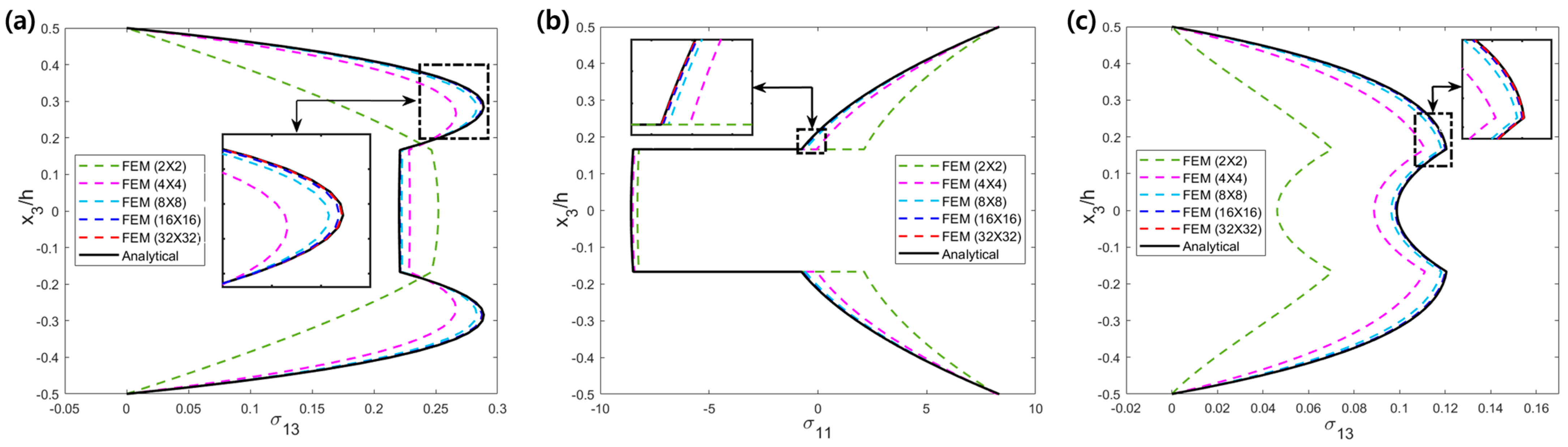
4.1. Validation of the Proposed FE Analysis Model

To examine the numerical errors that may occur during FE analysis, FE solutions based on EFSDTM_TN were validated against those obtained using the analytical approach. To this end, the convergence rate of the FE solutions was numerically verified by comparing the central deflections of the laminated composite and sandwich plates across different mesh densities, as listed in Table 2. The solutions for uniform temperature loading are not compared in Table 2 because of the absence of deflections.
From Table 2, it is observed that the FE solutions gradually converge to the analytical solutions with further refinement of the mesh. In addition, acceptable deflections were obtained when the FE model was discretized into an 8 × 8 mesh density or higher. Although an 8 × 8 mesh density is sufficient to describe the nodal displacement, potential numerical errors could arise when deriving in-plane and transverse shear stresses as these involve higher-order derivatives. The FE solutions for the in-plane and transverse shear stresses of [ 0 ° / 90 ° / 0 ° ] laminated composite plates are illustrated in Figure 2. The accuracies of these FE solutions, for various mesh density, were compared with those of analytical solutions. The distributions of the transverse shear stress given in Figure 2 were derived from following 3-D equilibrium equation:
σ 3 α = h 2 x 3 σ α β , β d x 3
Figure 2 shows that an FE model with a 16 × 16 mesh density or higher can yield precise numerical solutions for predicting the local distributions of in-plane and transverse shear stresses. In particular, it can be observed that the FE solutions with a 32 × 32 mesh density can closely approximate the analytical solutions, even for transverse shear stresses that require third-order derivatives. This means that the FE model with a 32 × 32 mesh density can be reasonably applied in thermomechanical analysis of laminated composite and sandwich structures with arbitrary geometry, loading, and boundary conditions.
Based on the numerical validation given in Table 2 and Figure 2, the FE solutions for all of the thermomechanical problems were obtained based on a 32 × 32 mesh density to ensure computational accuracy. Considering laminated composites and sandwich structures discretized with a 32 × 32 mesh density, kinematic unknown variables and corresponding total DOFs of the FE models were compared in Table 3.
Table 3 shows that the total DOFs of the proposed FE model are the same as FSDT, representing reductions of 45.5% to 55.6% as compared to the total DOFs of the HSDT and LCW, respectively. Therefore, the proposed FE model can clearly improve its computational efficiency in the process of thermo-mechanical analysis.

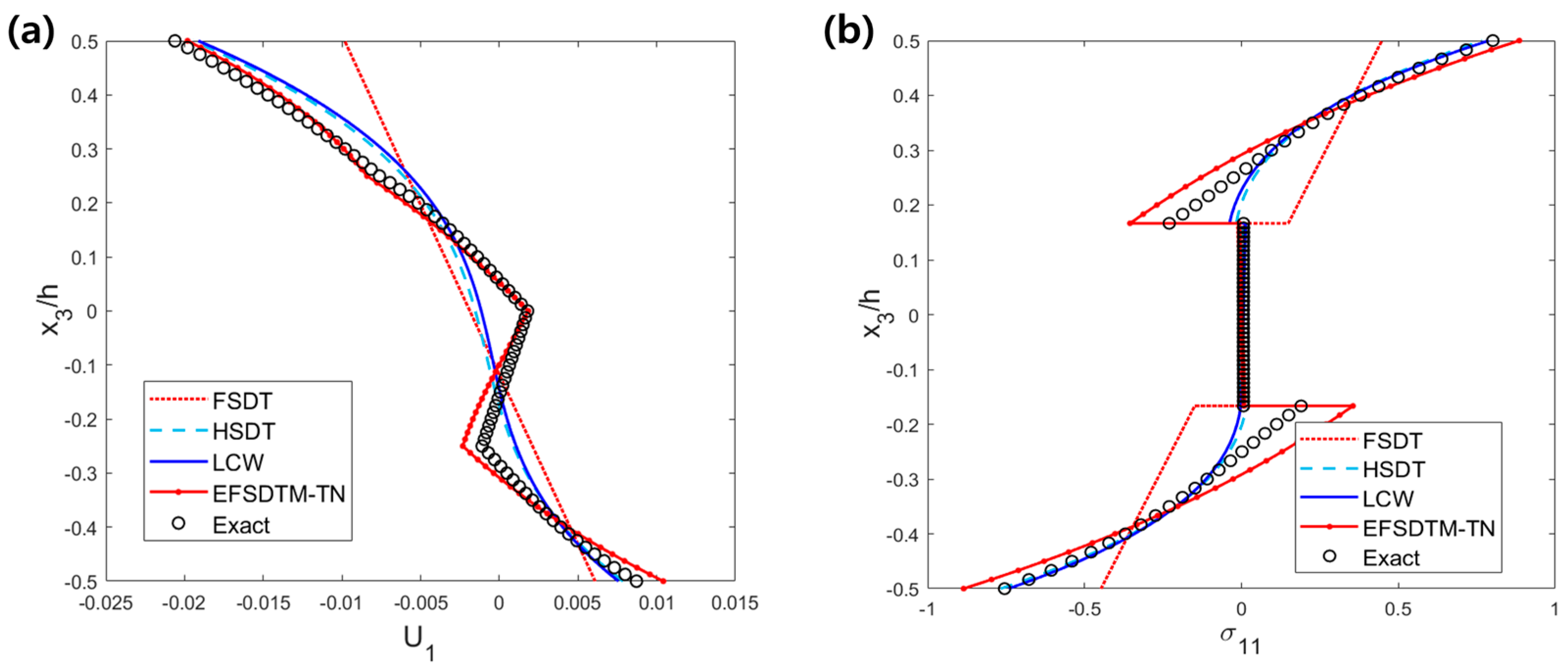
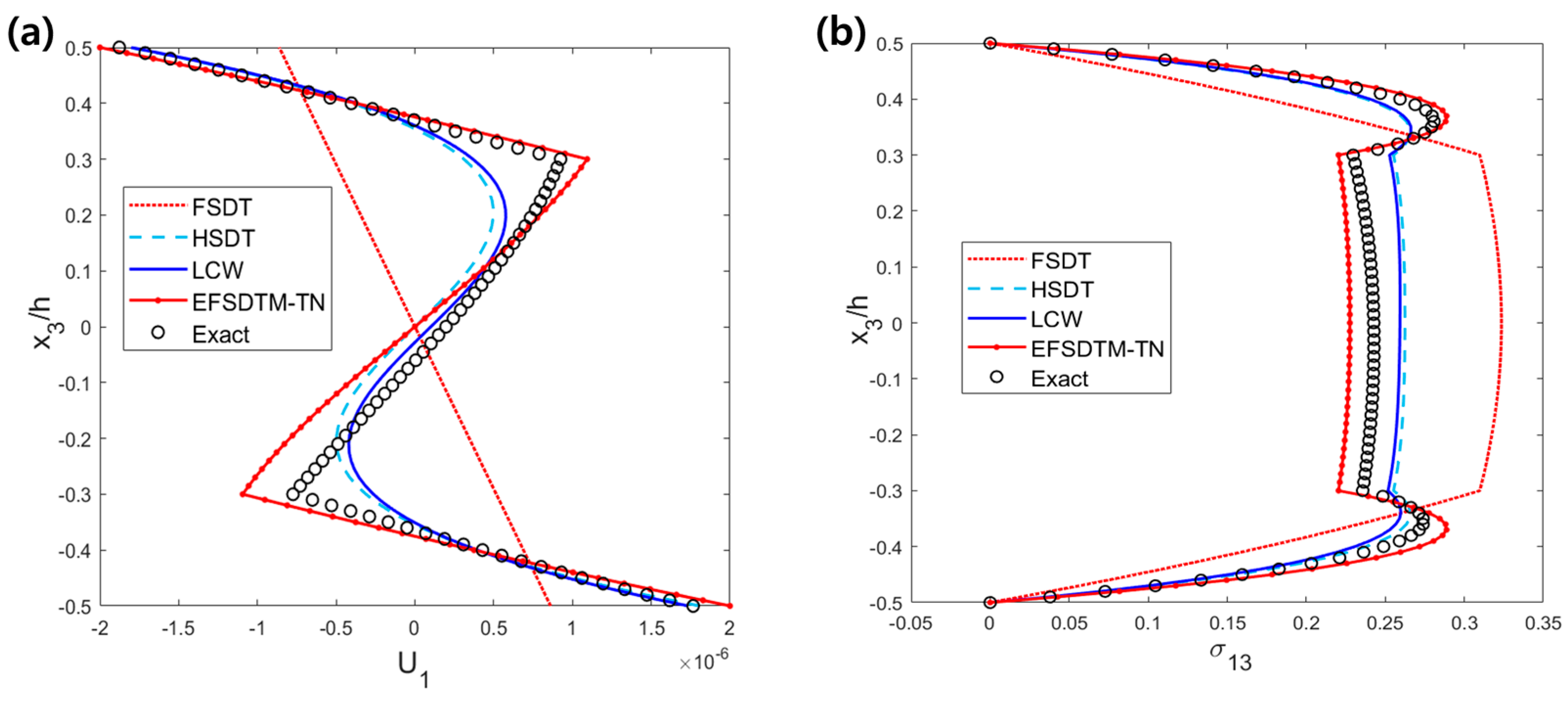
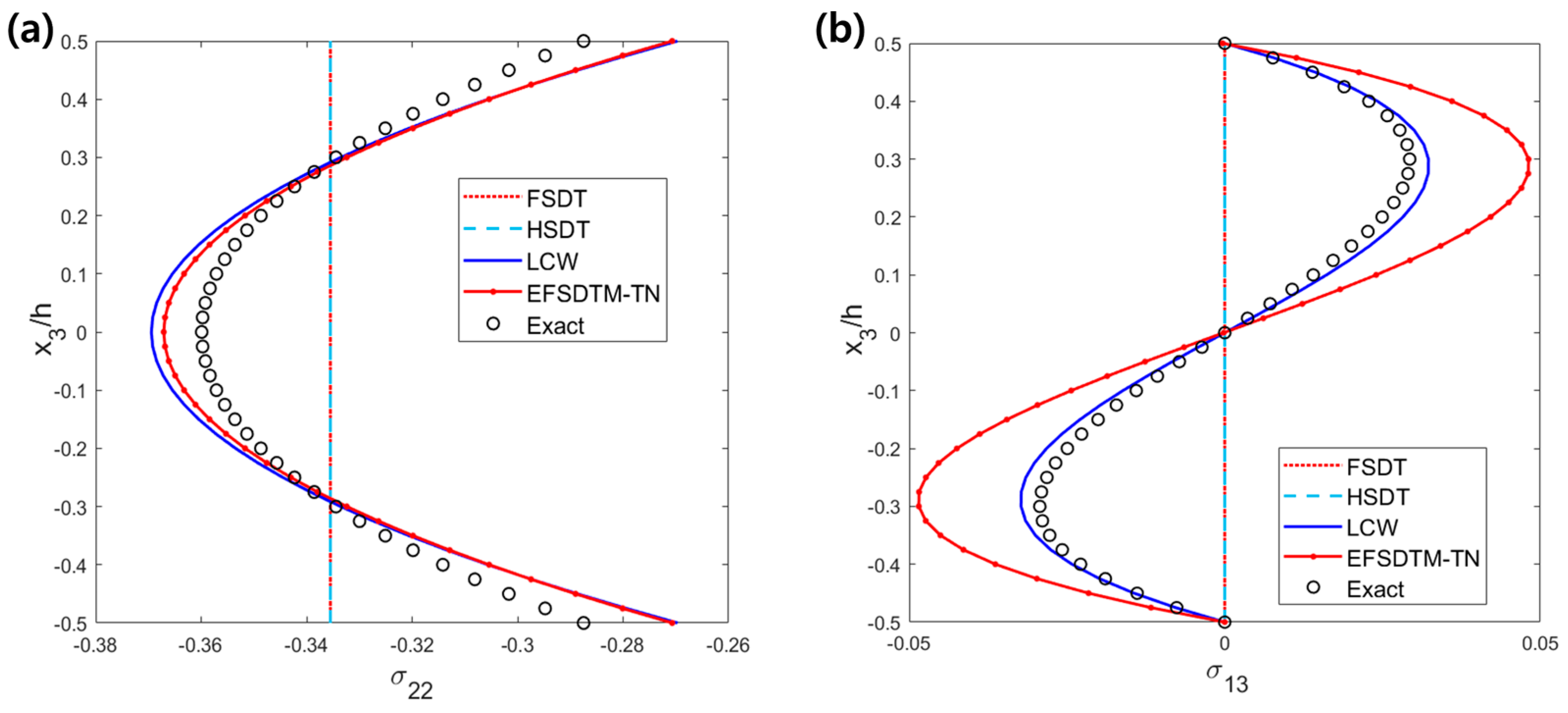
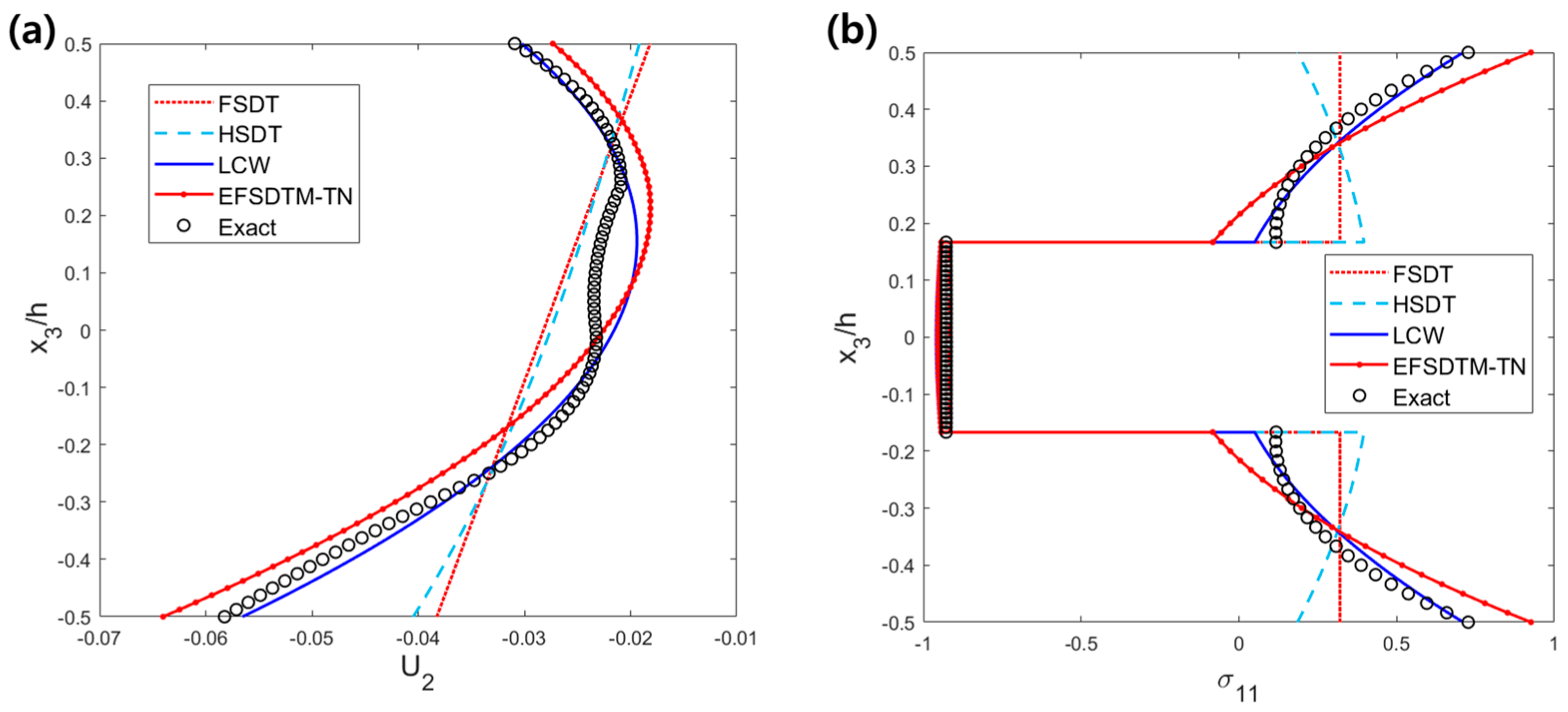
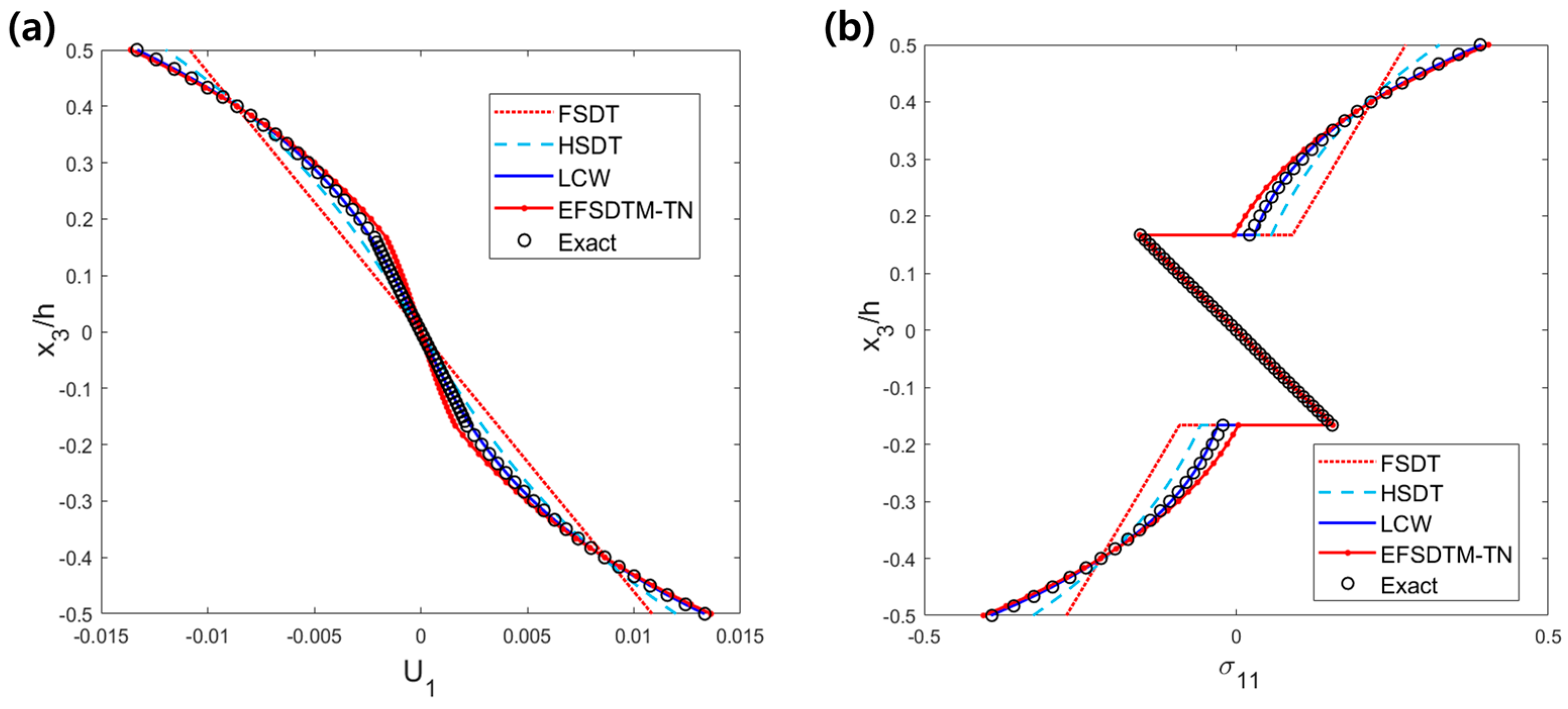
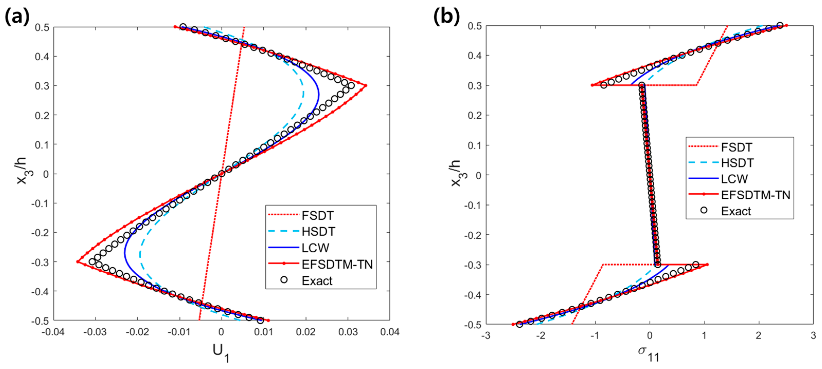
4.2. FE Solutions for the Mechanical Problem

In this subsection, the mechanical behaviors of the laminated composite and sandwich plates are evaluated to verify the numerical performance of the proposed FE model based on EFSDTM_TN. For the mechanical problems, transverse external loading ( P 3 0 ) was applied to the top surfaces of the laminated plates.
Figure 3 shows the mechanical solutions of the in-plane displacements and stresses for cross-ply laminated composite plates. From Figure 3a, it can be seen that the EFSDTM_TN precisely describes the unsymmetrical zigzag distribution of the in-plane displacement in [ 0 ° / 90 ° / 0 ° / 90 ° ] laminated composite plates. As shown in Figure 3b, EFSDTM_TN can provide a reliable local solution for the in-plane stress by capturing its noncontinuous distribution. However, other theories are only useful for predicting the global behavior of in-plane displacement.
For the [ 0 ° / C o r e / 0 ° ] sandwich plate, the distributions of the in-plane displacements and transverse shear stresses are shown in Figure 4. In terms of the in-plane displacement (Figure 4a), it should be noted that EFSDTM_TN can provide a sufficiently reliable solution for the in-plane displacement, even for a sandwich plate. In addition, as shown in Figure 4b, the severe kink distribution of the transverse shear stress is completely captured by EFSDTM_TN.

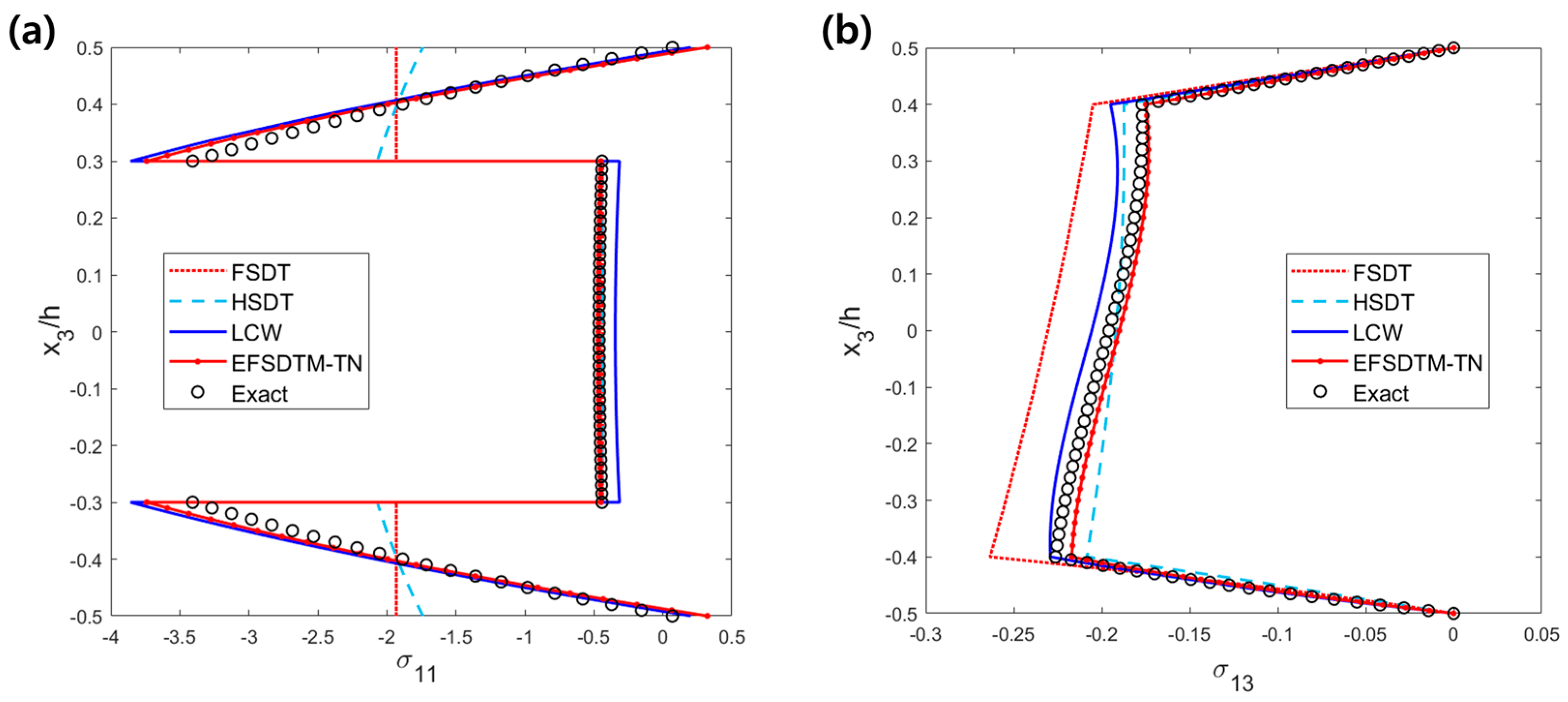
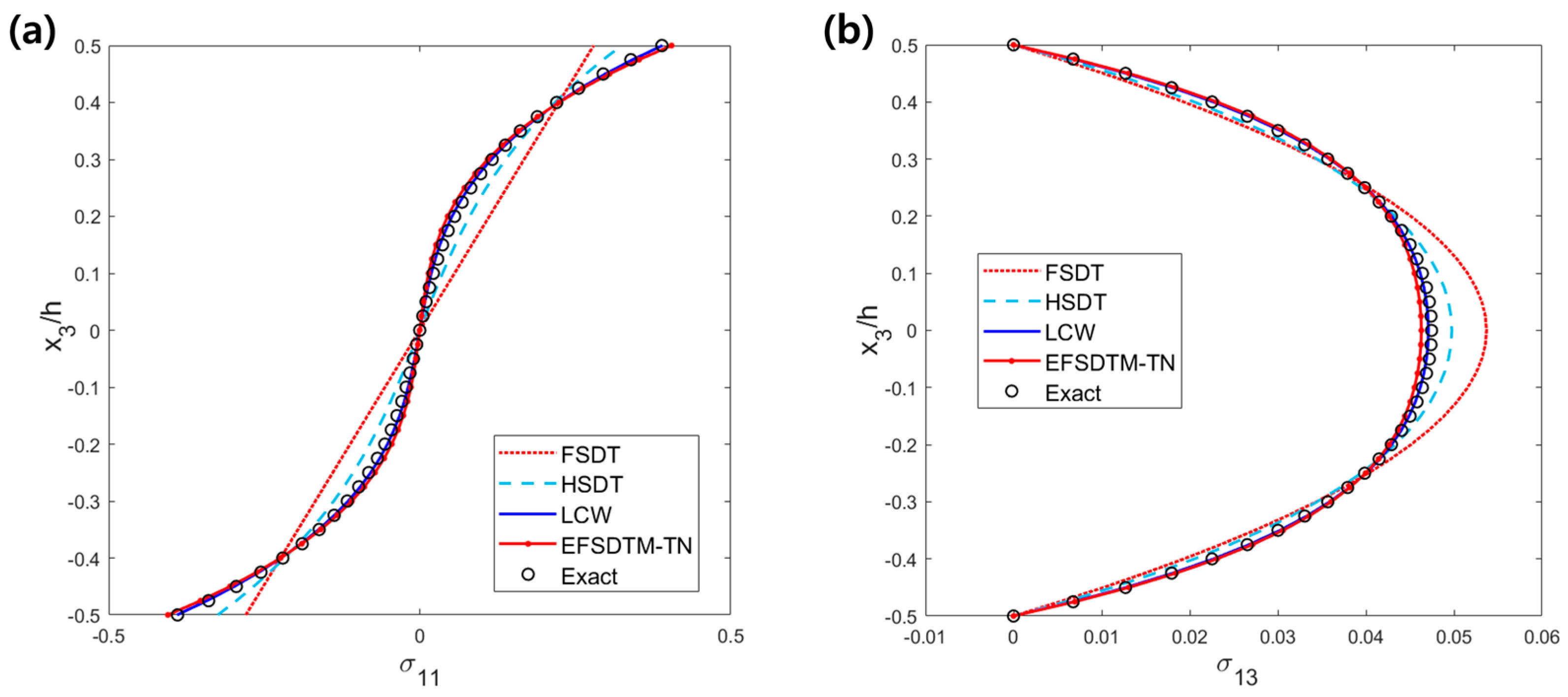
4.3. FE Solutions for the Thermal Problem

To further investigate the numerical capabilities related to the thermal analysis of laminated composites and sandwich plates, several thermal problems were also analyzed. In the case of thermal problems, uniform and linearly distributed temperatures were considered as external loads.
The in-plane and transverse shear stresses for a single-layer composite plate under uniform temperature loading ( T 0 0 ) are shown in Figure 5. As stated in Section 2.2, the transverse normal strain effect plays an important role in analyzing the thermal behaviors of laminated composites and sandwich plates. Furthermore, this effect becomes significant under a uniform temperature loading. Considering this aspect, FESDTM_TN and LCW, which reasonably consider the transverse normal strain effect, can accurately describe the thermal stresses of a single-layer composite plate under uniform temperature loading. Another interesting observation from Figure 5 is that the FSDT and HSDT, which cannot consider the transverse normal strain effect, provide meaningless solutions for these thermal stresses.
Figure 6 compares the thermal distributions of the in-plane displacements and stresses of the cross-ply laminated composite plates under uniform-temperature loading ( T 0 0 ). As shown in Figure 6, EFSDTM_TN and LCW can precisely capture not only the parabolic distributions of the in-plane displacements, but also the noncontinuous distributions of the in-plane stress, whereas the other theories fail to describe the local distributions of the corresponding thermal behaviors.
The thermal distributions of the in-plane and transverse shear stresses of the sandwich plates under uniform temperature loading ( T 0 0 ) are shown in Figure 7. As shown in Figure 7a, the thermal solutions obtained by EFSDTM_TN and LCW are in good agreement with the exact solutions by precisely describing the severe noncontinuous distribution of the in-plane stress. In addition, Figure 7b indicates that EFSDTM_TN and LCW provide the best compromised thermal solutions for the local distribution of the transverse shear stress. Consequently, Figure 5, Figure 6 and Figure 7 demonstrate that the transverse normal strain effect should be considered to accurately describe the thermal behavior of composite materials and sandwich structures subjected to uniform temperature loading.
For linear temperature loading ( T 1 0 ), the thermal distributions of the in-plane and transverse shear stresses of a single-layer composite plate are shown in Figure 8. Similar to Figure 5, it can be observed that the EFSDTM_TN and LCW provide reliable solutions in describing the in-plane and transverse shear stresses of a single-layer composite plate under linear temperature loading. Furthermore, as shown in Figure 8, the accuracy of all of the theories considered in this study improved, relative to those obtained under uniform temperature loading. This tendency is attributed to the fact that linear temperature loading can cause bending behavior of the plates.
Figure 9 and Figure 10 illustrate the corresponding thermal behavior when the linear temperature loading ( T 1 0 ) is applied to [ 0 ° / 90 ° / 0 ° ] laminated composite and [ 0 ° / C o r e / 0 ° ] sandwich plates, respectively. From Figure 9, it can be concluded that the solutions obtained by EFSDTM_TN and LCW closely approximate the exact solutions, while the local solutions obtained from other theories are relatively inaccurate. Considering the thermal behavior of the sandwich plate, as shown in Figure 10, it is noteworthy that the EFSDTM_TN provides the best compromised solution for the in-plane thermal stress by accurately capturing the noncontinuous local distribution. It can thus be concluded on the basis of Figure 3, Figure 4, Figure 5, Figure 6, Figure 7, Figure 8, Figure 9 and Figure 10 that EFSDTM_TN and LCW can provide reliable thermomechanical solutions for laminated composites and sandwich plates because these theories reasonably consider the transverse normal strain effect. Although LCW provides the most accurate solution for some thermal problems, EFSDTM_TN has a prominent computational advantage due to its C0-based 5-DOF FE implementation, which can be highly compatible with commercial FE software. Therefore, it can be concluded that the FE implementation based on EFSDTM_TN is a useful approach in the thermomechanical analysis of laminated composites and sandwich plates.

5. Conclusions

In this study, an FE formulation based on EFSDTM_TN was developed and numerically validated for the reliable thermomechanical analysis of laminated composites and sandwich plates. The main features of the proposed FE model are summarized as follows:
  • MVT was employed in the proposed FE model to independently assume the displacement (FEST_TN) and transverse stress (EHOPT_TN) fields. The displacement and transverse stress fields were systematically interconnected in the MVT by establishing reasonable energy relationships. Based on the predefined relationships, the proposed FE model can not only embrace the explicit computational advantages of FSDT_TN, such as the C0-based 5-DOF FE implementation, but also ensure the solution accuracy of EHOPT_TN.
  • The transverse displacement field was enhanced by incorporating the components of external temperature loading to account for the contribution of the transverse normal strain effect efficiently. Consequently, the proposed FE model can provide reliable thermal solutions without introducing additional unknown variables.
In the proposed FE model, an 8-node serendipity element was employed to effectively derive higher-order derivatives while evaluating stress distributions. To demonstrate the numerical performance of the proposed FE model, several cases of thermal-mechanical problems for laminated composites and sandwich structures were analyzed. The solutions obtained herein were then compared with those of conventional theories (FSDT, HSDT, and LCW), as well as 3-D exact solutions. From the numerical results, it can be concluded that the proposed FE model based on FESDTM_TN provides reliable thermomechanical solutions for laminated composites and sandwich plates. Consequently, it is expected that the proposed FE model can be applied to the thermomechanical analysis of laminated composites and sandwich structures with arbitrary geometries, loadings, and boundary conditions.

Author Contributions

Y.G. and S.-N.N.: conceptualization, methodology, validation, formal analysis, data curation, and writing—original draft preparation. J.-S.K.: conceptualization, methodology, validation, formal analysis, investigation, and writing—review and editing. H.P.: methodology, software, validation, visualization, and writing—original draft preparation. J.L. and J.-W.H.: conceptualization, methodology, validation, formal analysis, investigation, resources, supervision, funding acquisition, and writing—review and editing. Y.G. and S.-N.N. contributed equally as co-first authors. J.L. and J.-W.H. contributed equally as co-corresponding authors. All authors have read and agreed to the published version of the manuscript.

Funding

This research was supported by the National Research Foundation of Korea (NRF) grant, funded by the Korea government (MSIT) (NRF-No. 2022R1C1C1012599), and this research was supported by the National Research Foundation of Korea, 2020 (NRF-2020R1C1C1011970), and by the National Research Foundation of Korea (NRF) grant, funded by the Korean government (MSIT) (NRF-2018R1A5A7023490).

Data Availability Statement

Data available on request, subject to privacy or ethical considerations.

Conflicts of Interest

The authors declare no conflicts of interest.

Nomenclature

α γ ω thermal expansion coefficient.
C i j k l elasticity stiffness tensor.
Q α β γ ω reduced elastic stiffness tensor.
Δ T external temperature distribution consisting of T 0 and T 1 .
T 0 ,   T 1 uniform and linear temperature loadings.
σ ¯ α β 2 D ,   ε ¯ α β ,   γ ¯ 3 α stress and strain components based on the displacement field.
σ α 3 * ,   γ 3 α * stress and strain components based on the transverse stress field.
S α ( k ) coefficient of linear zigzag function to enforce shear continuity conditions.
S 3 ( k ) layer-wise constant to enforce continuity conditions of transverse normal displacement.
φ ( k ) layer-wise constant to enforce the plane stress condition.
Φ α β ( k ) in-plane warping functions derived from transverse stress field.
a α β ( k ) ,   b α β ( k ) ,   c α β ( k ) function of material properties to satisfy shear continuity conditions in the transverse stress field.
b 33 ( k ) ,   c 33 ( k ) function of material properties to satisfy continuity conditions of transverse normal displacement.
C α N ,   C α M in-plane correction factors derived by matching the force and moment resultants.
c α β N , M ( u * , T 0 , T 1 ) coefficient of in-plane correction factors ( C α N ,   C α M ).
N i shape functions for the element in FE implementation.
d ¯ e unknown displacements for each element.
d ¯ i unknown displacements for each node.
B ( m , b , s ) membrane, bending, and transverse shear part of the strain matrix.
K e stiffness matrix for each element.
K ( m ,   m b ,   b ,   s ) membrane, membrane-bending coupling, bending, and transverse shear part of the element stiffness matrix.
F M e external force vector for each element derived from the mechanical loading.
F T e external force vector for each element derived from the thermal loading.
T ˜ mechanical loading applied in each element.
F T o ( m ,   b ,   s ) membrane, bending, and transverse shear part of the external force vector derived from the uniform temperature loading.
F T 1 ( m ,   b ,   s ) membrane, bending, and transverse shear part of the external force vector derived from the linear temperature loading.

References

  1. Jones, R.M. Mechanics of Composite Materials, 2nd ed.; CRC Press: Boca Raton, FL, USA, 1999; pp. 1–53. [Google Scholar]
  2. Reddy, J.N. Mechanics of Laminated Composite Plates and Shells: Theory and Analysis, 2nd ed.; CRC Press: Boca Raton, FL, USA, 2004; pp. 81–106. [Google Scholar]
  3. Mindlin, R.D. Influence of rotary and shear on flexural motions of isotropic. ASME J. Appl. Mech. 1951, 18, 31–38. [Google Scholar] [CrossRef]
  4. Reissner, E. The effect of transverse shear deformation on the bending of elastic plates. ASME J. Appl. Mech. 1945, 12, 69–77. [Google Scholar] [CrossRef]
  5. Reissner, E. On a mixed variational theorem and on shear deformable plate theory. Int. J. Numer. Methods Eng. 1986, 23, 193–198. [Google Scholar] [CrossRef]
  6. Whitney, J.M.; Leissa, A.W. Analysis of heterogeneous anisotropic plates. ASME J. Appl. Mech. 1969, 36, 261–266. [Google Scholar] [CrossRef]
  7. Thai, H.T.; Choi, D.H. A simple first-order shear deformation theory for laminated composite plates. Compos. Struct. 2013, 106, 754–763. [Google Scholar] [CrossRef]
  8. Reddy, J.N. A simple higher-order theory for laminated composite plates. ASME J. Appl. Mech. 1984, 51, 745–752. [Google Scholar] [CrossRef]
  9. Carrera, E. Evaluation of layerwise mixed theories for laminated plates analysis. AIAA J. 1998, 36, 830–839. [Google Scholar] [CrossRef]
  10. Ferreira, A.J.M. A formulation of multiquadric radial basis function method for the analysis of laminated composite plates. Compos. Struct. 2003, 59, 385–392. [Google Scholar] [CrossRef]
  11. Wu, Z.; Chen, W.J. Refined global-local higher-order theory and finite element for laminated plates. Int. J. Numer. Meth. Eng. 2007, 69, 1627–1670. [Google Scholar]
  12. Mantari, J.L.; Oktem, A.S.; Soares, C.G. A new trigonometric layerwise shear deformation theory for the finite element analysis of laminated composite and sandwich plates. Comput. Struct. 2012, 94, 45–53. [Google Scholar] [CrossRef]
  13. Mantari, J.L.; Soares, C.G. Generalized layerwise HSDT and finite element formulation for symmetric laminated and sandwich composite plates. Compos. Struct. 2013, 105, 319–331. [Google Scholar] [CrossRef]
  14. Di Sciuva, M. Bending, vibration and buckling of simply supported thick multilayered orthotropic plates: An evaluation of a new displacement model. J. Sound Vib. 1986, 105, 425–442. [Google Scholar] [CrossRef]
  15. Cho, M.; Parmerter, R.R. An efficient higher order plate theory for laminated composites. Compos. Struct. 1992, 20, 113–123. [Google Scholar] [CrossRef]
  16. Cho, M.; Parmerter, R.R. Efficient higher-order plate theory for general lamination configuration. AIAA J. 1993, 31, 1299–1306. [Google Scholar] [CrossRef]
  17. Versino, D.; Gherlone, M.; Mattone, M.; DiSciuva, M.; Tessler, A. C0 triangular elements based on the refined zigzag theory for multilayer composite and sandwich plates. Compos. Part B Eng. 2013, 44, 218–230. [Google Scholar] [CrossRef]
  18. Ren, X.; Chen, W.; Wu, Z. A C0-type zig-zag theory and finite element for laminated composite and sandwich plates with general configurations. Arch. Appl. Mech. 2012, 82, 391–406. [Google Scholar]
  19. Kim, J.S.; Cho, M. Enhanced modeling of laminated and sandwich plates via strain energy transformation. Compos. Sci. Technol. 2006, 66, 1575–1587. [Google Scholar] [CrossRef]
  20. Kim, J.S.; Cho, M. Enhanced first-order theory based on mixed formulation and transverse normal effect. Int. J. Solids Struct. 2007, 44, 1256–1276. [Google Scholar] [CrossRef]
  21. Han, J.W.; Kim, J.S.; Cho, M. Improved finite element viscoelastic analysis of laminated structures via the enhanced first-order shear deformation theory. Compos. Struct. 2017, 180, 360–377. [Google Scholar] [CrossRef]
  22. Miguel, A.G.; Carrera, E.; Pagani, A.; Zappino, E. Accurate evaluation of interlaminar stresses in composite laminates via mixed one-dimensional formulation. AIAA J. 2018, 56, 4582–4594. [Google Scholar] [CrossRef]
  23. Wu, B.; Pagani, A.; Chen, W.Q.; Carrera, E. Geometrically nonlinear refined shell theories by Carrera Unified Formulation. Mech. Adv. Mater. Struct. 2021, 28, 1721–1741. [Google Scholar] [CrossRef]
  24. Yousuf, L.S. Largest lyapunov exponent parameter of stiffened carbon fiber reinforced epoxy composite laminated plate due to critical buckling load using average logarithmic divergence approach. Mathematics 2022, 10, 2020. [Google Scholar] [CrossRef]
  25. Yang, S.; Sun, X.; Cai, Z. Isogeometric analysis for free vibration of functionally graded plates using a new quasi-3D spectral displacement formulation. Mathematics 2023, 11, 2660. [Google Scholar] [CrossRef]
  26. Petrolo, M.; Iannotti, P. Best Theory Diagrams for Laminated Composite Shells Based on Failure Indexes. Aerotec. Missili Spaz. 2023, 102, 199–218. [Google Scholar] [CrossRef]
  27. Arruda, M.R.T.; Trombini, M.; Pagani, A. Implicit to Explicit Algorithm for ABAQUS Standard User-Subroutine UMAT for a 3D Hashin-Based Orthotropic Damage Model. Appl. Sci. 2023, 13, 1155. [Google Scholar] [CrossRef]
  28. Petrolo, M.; Augello, R.; Carrera, E.; Scano, D.; Pagani, A. Evaluation of transverse shear stresses in layered beams/plates/shells via stress recovery accounting for various CUF-based theories. Compos. Struct. 2023, 307, 116625. [Google Scholar] [CrossRef]
  29. Lo, K.H.; Christensen, R.M.; Wu, E.M. A higher-order theory of plate deformation. Part 2: Laminated plates. ASME J. Appl. Mech. 1977, 44, 669–676. [Google Scholar] [CrossRef]
  30. Jonnalagadda, K.D.; Tauchert, T.R.; Blandford, G.E. Higher order thermoelastic composite plate theories, analytical comparison. J. Therm. Stress. 1993, 16, 265–284. [Google Scholar] [CrossRef]
  31. Kant, T.; Khare, R. Finite element thermal stress analysis of composite laminates using a higher-order theory. J. Therm. Stress. 1994, 17, 229–255. [Google Scholar] [CrossRef]
  32. Rohwer, K.; Rolfes, R.; Sparr, H. Higher-order theories for thermal stresses in layered plates. Int. J. Solids Struct. 2001, 38, 3673–3787. [Google Scholar] [CrossRef]
  33. Zenkour, A.M. Analytical solution for bending of cross-ply laminated plates under thermo-mechanical loading. Compos. Struct. 2004, 65, 367–379. [Google Scholar] [CrossRef]
  34. Matsunaga, H.A. Comparison between 2-D single-layer and 3-D layerwise theories for computing interlaminar stresses of laminated composite and sandwich plates subjected to thermal loadings. Compos. Struct. 2004, 64, 161–177. [Google Scholar] [CrossRef]
  35. Patel, B.P.; Lele, A.V.; Ganapathi, M.; Gupta, S.S.; Sambandam, C.T. Thermo-flexural analysis of thick laminates of bimodulus composite materials. Compos. Struct. 2004, 63, 11–20. [Google Scholar] [CrossRef]
  36. Khare, R.K.; Kant, T.; Garg, A.K. Closed-form thermo-mechanical solutions of higher-order theories of cross-ply laminated shallow shells. Compos. Struct. 2003, 59, 313–340. [Google Scholar] [CrossRef]
  37. Noor, A.K.; Malik, M. An assessment of five modeling approaches for thermomechanical stress analysis of laminated composite panels. Comput. Mech. 2000, 25, 43–58. [Google Scholar] [CrossRef]
  38. Carrera, E. An assessment of mixed and classical theories for the thermal stress analysis of orthotropic multilayered plates. J. Therm. Stress. 2000, 23, 797–831. [Google Scholar] [CrossRef]
  39. Carrera, E.; Ciuffreda, A. Closed-form solutions to assess multilayered-plate theories for various thermal stress problems. J. Therm. Stress. 2004, 27, 1001–1031. [Google Scholar] [CrossRef]
  40. Cho, M.; Oh, J. Higher order zig-zag plate theory under thermo-electric-mechanical loads combined. Compos. Part B Eng. 2003, 34, 67–82. [Google Scholar] [CrossRef]
  41. Cho, M.; Oh, J. Higher order zig-zag theory for fully coupled thermo-electric–mechanical smart composite plates. Int. J. Solids Struct. 2004, 41, 1331–1356. [Google Scholar] [CrossRef]
  42. Oh, J.; Cho, M. A Finite Element Based on Cubic Zig-zag Plate Theory for the Prediction of Thermo-electric-mechanical Behaviors. Int. J. Solids Struct. 2004, 41, 1357–1375. [Google Scholar] [CrossRef]
  43. Oh, J.; Cho, M. Higher order zig-zag theory for smart composite shells under mechanical-thermo-electric loading. Int. J. Solids Struct. 2007, 44, 100–127. [Google Scholar] [CrossRef]
  44. Kapuria, S.; Achary, G.G.S. An efficient higher order zigzag theory for laminated plates subjected to thermal loading. Int. J. Solids Struct. 2004, 41, 4661–4684. [Google Scholar] [CrossRef]
  45. Wu, Z.; Chen, W. A quadrilateral element based on refined global-local higher-order theory for coupling bending and extension thermo-elastic multilayered plates. Int. J. Solids Struct. 2007, 44, 3187–3217. [Google Scholar]
  46. Wu, Z.; Cheung, Y.K.; Lo, S.H.; Chen, W. On the thermal expansion effects in the transverse direction of laminated composite plates by means of a global–local higher-order model. Int. J. Mech. Sci. 2010, 52, 970–981. [Google Scholar]
  47. Zenkour, A.M. Thermal bending of layered composite plates resting on elastic foundations using four-unknown shear and normal deformations theory. Compos. Struct. 2015, 122, 260–270. [Google Scholar] [CrossRef]
  48. Ramos, I.A.; Mantari, J.L.; Zenkour, A.M. Laminated composite plates subject to thermal load using trigonometrical theory based on Carrera Unified Formulation. Compos. Struct. 2016, 143, 324–335. [Google Scholar] [CrossRef]
  49. Oh, J.; Cho, M.; Kim, J.S. Enhanced lower-order shear deformation theory for fully coupled electro-thermo-mechanical smart laminated plates. Smart Mater. Struct. 2007, 16, 2229–2241. [Google Scholar] [CrossRef]
  50. Han, J.W.; Kim, J.S.; Cho, M. New enhanced first-order shear deformation theory for thermo-mechanical analysis of laminated composite and sandwich plates. Compos. Part B Eng. 2017, 116, 422–450. [Google Scholar] [CrossRef]
  51. Han, J.W.; Kim, J.S.; Cho, M. Improved thermo-mechanical stress prediction of laminated composite and sandwich plates using enhanced LCW theory. Eur. J. Mech. A/Solids 2017, 66, 143–157. [Google Scholar] [CrossRef]
  52. Khalid, S.; Lee, J.; Kim, H.S. Series solution-based approach for the Interlaminar stress analysis of smart composites under thermo-electro-mechanical Loading. Mathematics 2022, 10, 268. [Google Scholar] [CrossRef]
  53. Avey, M.; Fantuzzi, N.; Sofiyev, A.H. Analytical solution of stability problem of nanocomposite cylindrical shells under combined loadings in thermal environments. Mathematics 2023, 11, 3781. [Google Scholar] [CrossRef]
  54. Azzara, R.; Carrera, E.; Filippi, M.; Pagani, A. Vibration analysis of thermally loaded isotropic and composite beam and plate structures. J. Therm. Stress. 2023, 46, 369–386. [Google Scholar] [CrossRef]
  55. Wang, D.; Hui, J.; Cao, W.; Yang, Y.; Wan, Y.; Zuo, H.; Zhang, B. The influence of geometric imperfections on post-buckling behavior and free vibrations of a fiber-reinforced composite laminated plate under thermal loading. Compos. Struct. 2023, 306, 116568. [Google Scholar] [CrossRef]
  56. Smolin, I.Y.; Zimina, V.A.; Buyakova, S.P. Estimation of Residual Thermal Stresses in a Layered Ceramic Composite. Mech. Compos. Mater. 2023, 58, 823–834. [Google Scholar] [CrossRef]
  57. Pagano, N.J. Exact solutions for composite laminates in cylindrical bending. J. Compos. Mater. 1969, 3, 398–411. [Google Scholar] [CrossRef]
  58. Pagano, N.J.; Hatfield, S.J. Elastic behavior of multilayered bidirectional Composites. AIAA J. 1972, 10, 931–933. [Google Scholar] [CrossRef]
Figure 1. Geometric shape and reference coordinates of laminated plates.
Mathematics 12 00963 g001
Figure 2. Comparison between analytical and FE solutions for stresses of [ 0 ° / 90 ° / 0 ° ] laminated composite plates: (a) transverse shear stresses under mechanical loading; (b) in-plane stresses under uniform temperature loading; (c) transverse shear stresses under linear temperature loading.
Mathematics 12 00963 g002
Figure 3. Mechanical solutions for cross-ply laminated composite plates: (a) in-plane displacements for [ 0 ° / 90 ° / 0 ° / 90 ° ] composite plates; (b) in-plane stresses for [ 0 ° / 90 ° / 0 ° ] composite plates.
Mathematics 12 00963 g003
Figure 4. Mechanical solutions for [ 0 ° / C o r e / 0 ° ] sandwich plate: (a) in-plane displacements; (b) transverse shear stresses.
Mathematics 12 00963 g004
Figure 5. Thermal solutions for a single-layer composite plate under uniform temperature loading: (a) in-plane stresses; (b) transverse shear stresses.
Mathematics 12 00963 g005
Figure 6. Thermal solutions for cross-ply laminated composite plates under uniform temperature loading: (a) in-plane displacements for [ 0 ° / 90 ° / 0 ° / 90 ° ] composite plates; (b) in-plane stresses for [ 0 ° / 90 ° / 0 ° ] composite plates.
Mathematics 12 00963 g006
Figure 7. Thermal solutions for sandwich plates under uniform temperature loading: (a) in-plane stresses for [ 0 ° / C o r e / 0 ° ] sandwich plate; (b) transverse stresses for [ 0 ° / C o r e / 90 ° ] sandwich plate.
Mathematics 12 00963 g007
Figure 8. Thermal solutions for a single-layer composite plate under linear temperature loading: (a) in-plane stresses; (b) transverse shear stresses.
Mathematics 12 00963 g008
Figure 9. Thermal solutions for [ 0 ° / 90 ° / 0 ° ] laminated composite plates under linear temperature loading: (a) in-plane displacements; (b) in-plane stresses.
Mathematics 12 00963 g009
Figure 10. Thermal solutions for [ 0 ° / C o r e / 0 ° ] sandwich plate under linear temperature loading: (a) in-plane displacements; (b) in-plane stresses.
Mathematics 12 00963 g010
Table 1. List of layup configurations for composite and sandwich plates.
CaseLayupLayer Thickness
Case 1Single layerEach layer: h
Case 2[0/90/0]Each layer: h / 3
Case 3[0/90/0/90]Each layer: h / 4
Case 4[0/Core/0]Face sheet: h / 5 , Core: ( 3 / 5 ) × h
Case 5[0/Core/90]Face sheet: h / 10 , Core: ( 4 / 5 ) × h
Table 2. Convergence rate of central deflections for EFSDTM_TN.
LoadingLayupAnalytical
Solutions
Finite Element (FE) Solutions
Mesh Density
2 by 24 by 48 by 816 by 1632 by 32
P 3 0 Case 11.661591.265591.642811.660511.661531.66159
Case 22.198451.833532.181862.197492.198392.19845
Case 32.036511.600412.015372.035282.036432.03650
Case 40.546630.435130.541480.546340.546620.54663
Case 50.730950.613160.725610.730640.730930.73095
T 1 0 Case 10.0105520.0098670.0104980.0105480.0105510.010552
Case 20.0109650.0102130.0109100.0109620.0109650.010965
Case 30.00871880.00804040.00866950.00871570.00871870.0087188
Case 40.0167100.0156220.0166290.0167050.0167090.016710
Case 50.0328760.0300040.0326850.0328640.0328750.032876
Table 3. Kinematic unknown variables and total DOFs of the FE models (32 × 32 mesh density).
TheoryElement TypeDOFs per NodeNumber of Node
( 32 × 32 Mesh Density)
Total DOFs
FSDTC0 element5320116,005
HSDTC0 element9320128,809
LCWC0 element11320135,211
EFSDTM_TNC0 element5320116,005
Disclaimer/Publisher’s Note: The statements, opinions and data contained in all publications are solely those of the individual author(s) and contributor(s) and not of MDPI and/or the editor(s). MDPI and/or the editor(s) disclaim responsibility for any injury to people or property resulting from any ideas, methods, instructions or products referred to in the content.

