1. Introduction
One third of global greenhouse gas (GHG) releases are attributed to the source materials responsible for producing power, such as fossil fuels, petroleum, and gasses. India’s present attempts at commercial improvement are leading to an increase in the nation’s energy requirements. Indeed, the maximal extraction of natural resources is a necessary component of the expansion of a country’s economic growth [
1]. The changing climate could result in a shift in the planet’s natural balance. The UNFCCC (UN Framework for Convention on Climatic Changes) and the PT (Paris Treaty) have both received submissions of INDCs (intended national voluntarily determined contributions), with the latter aimed at limiting the rise in the global mean temp. to far below 2 °C.
Among the alternatives mentioned above, the most well-known and prevalent sources of clean energy in India are wind and solar [
2]. The power scenario in India up to 2022 is shown in
Figure 1.
By 2023, India aims to produce 180 GW of power in the form of renewable sources. Of the 180 GW, 5 GW will come from small hydroelectric plants, 10 GW from biofuels, 100 GW from photovoltaic cells, and 65 GW from wind farms [
3]. The government must provide 330,000 new jobs in order to meet the challenging goal of 180 GW of sustainable power generation by 2023 [
4].
Disabling an RSC results in a loss of power control and the occurrence of significant transients immediately after the fixation of the fault. In some cases, this may necessitate disconnecting the machine from the grid [
5]. The power scenario expected by 2039–2040 is in
Figure 2.
However, the operation limit of a changing-velocity WECS may be split into four main zones. In first zone, low wind speeds do not produce enough energy. In second zone, the structure is optimized to produce maximum power while adjusting to changes in wind velocity using the maximum/peak power point tracking (MPPT) approach, in which the angle of the blade pitch is fixed to its perfect value. In third zone, when the wind velocity goes above the predefined values, the angle of the pitch is adjusted to control the electrical energy generated around its predefined value. In the fourth zone, high wind speeds can cause damage to the wind turbine (WT), requiring the devices that work in emergency situations to stop the turbine so that the damage can be prevented [
6]. A. Santhi Mary Antony et al. [
7] presented simulation results for different types of WECS generators, including the permanent magnet synchronous generator (PMSG), squirrel cage induction generator (SCIG), and DFIGs with bridge and bridgeless configurations, all of which utilize a WT with a horizontal axis. The conventional system couples the RSC and GSC through a direct current capacitor link, which helps in to maintain a steady direct current voltage and reduce voltage ripple but also has the disadvantage of being bulky [
8].
However, with a direct connection to the power grid, the DFIG can struggle with more variations in torque and harmonic content in the grid, leading to shaft vibration, increased mechanical wear and tear, and higher maintenance costs [
9]. To mitigate these issues, ESSs can be employed to store excess wind energy during high-production periods. Additionally, integrating the system of energy storage directly at the DC link terminals of the DFIG to maintain the variability of the WE on the grid side has been proposed by Singh et al. [
10].
According to the reviewed literature, adaptation control has been employed less extensively than vector control with DFIG power transformers. This same application of adaption control to grid-connected photo voltaic arrays has shown outstanding performance. To exploit its advantages, Singh et al. [
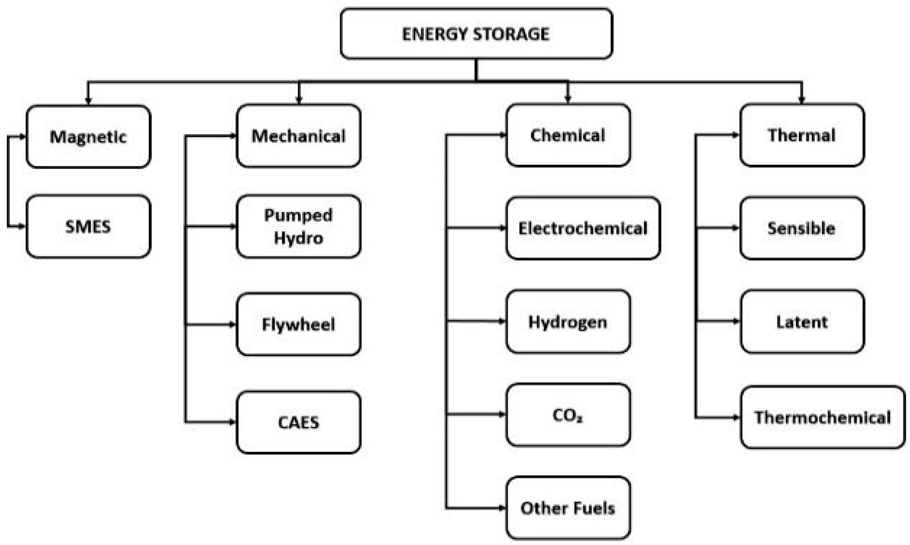
11] used adaption control to effectively operate the GSC of an induction generator for a WT. It has also been discovered that the use of adaption control methods leads to increased weighted computation efficiency, less fluctuations, and a quicker settling time, which are critical factors in determining power balancing, PQ, resilience, and the maximum supply of energy fed into network in rotary-machine-integrated systems. Different types of energy storage systems are shown in
Figure 3, some of which are briefly explained herein. Batteries are the most commonly used energy storage devices and store electrical energy in a chemical form. Some common types of batteries are lithium-ion, lead–acid, nickel–cadmium, and sodium-ion, etc. Flywheels store energy in the form of rotational kinetic energy. A flywheel consists of a rotor that rotates at a high speed in a vacuum, and energy is extracted by slowing down the rotor. In the case of pumped hydroelectric storage, energy is stored by pumping water uphill to a reservoir during periods of low demand and then releasing it through a turbine to generate electricity during high-demand periods. In the case of compressed air energy storage, energy is stored by compressing air in an underground reservoir during low-demand periods and then releasing it through a turbine to generate electricity during high-demand periods. Thermal energy storage involves storing energy in the form of heat; common types of thermal energy storage are water-based systems, phase-change materials, molten salt systems, etc. Superconducting magnetic energy storage stores energy in the magnetic field generated by a superconducting coil, which can be used to generate electricity during periods of peak demand. Hydrogen energy storage involves using excess electricity to produce hydrogen through electrolysis, which can then be stored and used to generate electricity during periods of peak demand. Capacitors store energy in an electric field and are commonly used in electronics and power electronics.
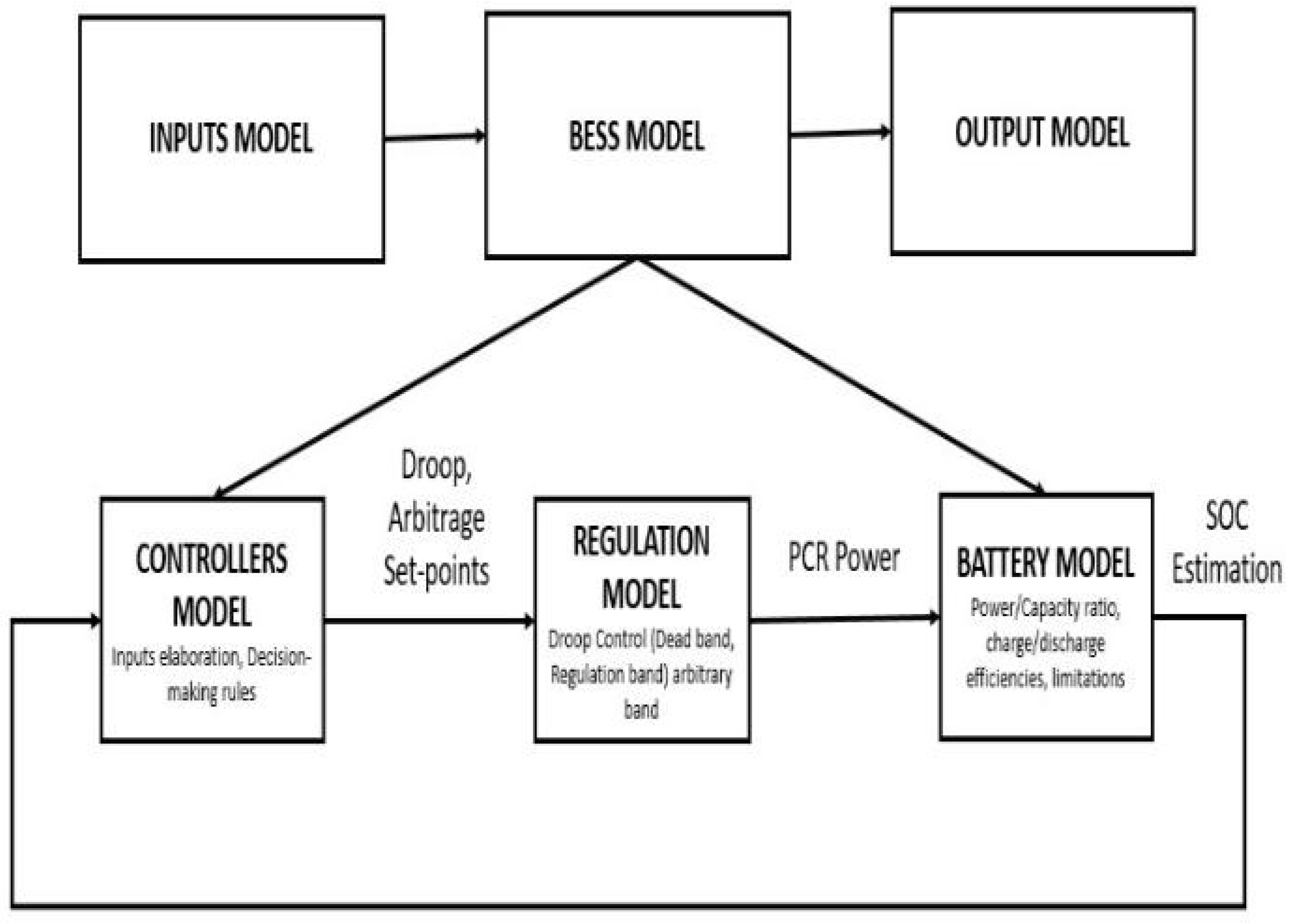
To achieve these objectives, the proposed control scheme integrates a BESS with a direct current link through a power conversion device which compensates for wind alterations and employs a high-order adaption control for the GSC of the DFIG, supplying the system with a consistent amount of high energy [
12]. An application scenario of an energy storage system is shown in
Figure 4.
The control architecture’s purpose is to maintain a constant V and f at the terminal of the DFIG in response to wind velocity alterations and additional load variations. However, developing a control system for a grid-integrated WECS is a challenging task due to the erratic patterns of wind velocity. However, the high switching frequency associated with DTC leads to increased current harmonic distortion, elevated electromagnetic torque fluctuations, and elevated heating in IGBT components [
13]. These controllers, including back stepping control, feedback linearization control, H-infinity control, adaptive control, model predictive control, and sliding model control, have the ability to handle nonlinearities in a wide range of operations [
14].
The use of sliding mode control (SMC) is advantageous in grid-tied DFIG systems due to its quick calculation time and straightforward installation. Fuzzy logic (FL) and artificial neural networks (ANNs) are examples of AI (artificial intelligence) approaches that are employed to improve the effectiveness of SMC and to lessen the buzzing influence. In HOSMCs (higher-order sliding mode controllers), the super twisting technique (STT) is frequently employed [
15]. Several state of charge (SOC) restrictions have also been taken into consideration in distinct experiments towards the fuzzy-logic-based charging and discharging control of Li-ion battery systems [
16]. An FL-based BESS is mainly proposed to regulate the condition of a battery’s SOC. This SOC restriction was set in the range of 50% to 100% [
17]. Martinez et al. [
18] also employed a similar approach, utilizing 5 MF to create 21 FL rules to restrict the battery’s SOC.
In the coastal and Himalayan regions of Himachal Pradesh, wind input conditions vary greatly, with some areas experiencing high wind speeds that are not constant. Data for an entire year from Dharamshala in the Kangra district of Himachal Pradesh are analyzed and depicted in
Figure 5. Twin capacitors are charged using a DC link voltage thanks the R and L series connection of the BESS. Quick velocity resolution, power control, and the regulation of the DC link voltage via the GSC are all ensured by the recommended converters and control techniques applied to the RSC. Using MATLAB Simulation, the overall efficiency of the suggested technique was confirmed, has and it was shown to work superbly under typical operational settings.
The contributions of this paper are as follows: first, we recommend various energy storage devices for direct current links in place of capacitors and provide scenarios of their application in a wind energy conversion system. We observed the wind speeds at Dharamshala in HP for an entire year.
Section 2 provides a model and control for a doubly-fed-induction-generator-based wind energy conversion system;
Section 3 provides the design of a battery energy storage system;
Section 4 explains the design of a fractional order proportional integral derivative controller used in the converter. In
Section 5, we provide an analysis of the proposed technique in MATLAB. In
Section 6, the results from the simulation performed in this study are presented and analyzed.
Section 7 concludes the paper. This paper investigates the impact of a BESS on the performance and stability of the system under varying wind conditions. This research problem statement could contribute to the development of more efficient and reliable DFIG-based WECSs with BESSs, which can help increase the prevalence of renewable energy sources in the power grid. The performance of the proposed algorithms is discussed, and potential areas for future research are outlined.
3. Design of BESS (Battery Energy Storage System)
Various energy storage devices can also be used in DFIG-based WECS, depending upon the specific requirements of the system and the available technologies. The major advantage of this is that the BESS has a high power density and fast response time, making it well-suited for use in applications that require a high power output and rapid load response, such as wind energy systems. It has a long life cycle and can operate in harsh environments, making it a reliable and durable option for energy storage in wind energy systems. For this reason, many authors use a BESS rather than another energy storage device. The characteristics of different ESS devices are provided by [
21].
Such a model analyses the overall power transfers across a battery bank and updates the device’s SOC across the specified time period while considering its steady-state performance [
22,
23,
24]. This approach does not take into account factors such as lifetime deterioration, temperature changes, capacity fluctuations that are dependent upon operational voltage, and particular electrical circuits [
25,
26,
27]. The battery model obtains the intended 1PSET (specified in units of nominal capacity) from its regulation model and updates the SOC of the battery. The BESS model and parameters are shown in
Figure 10. According to generator conventions, the calculation of the actual power, 1PB, needed from or inserted into the battery is described in Equations (22) and (23) as:
where
are the discharge and charge efficiencies of the BESS, respectively. It should be noted that the outcome of the BESS is calculated in the form of
. This implies that a portion of the BESS’s usable capacity may be put to use for other tasks, such as energy storage or buffering.
At each time step, the SOC variation can be computed by Equation (24) as follows:
where EPR stands for the energy–power ratio of the BESS.
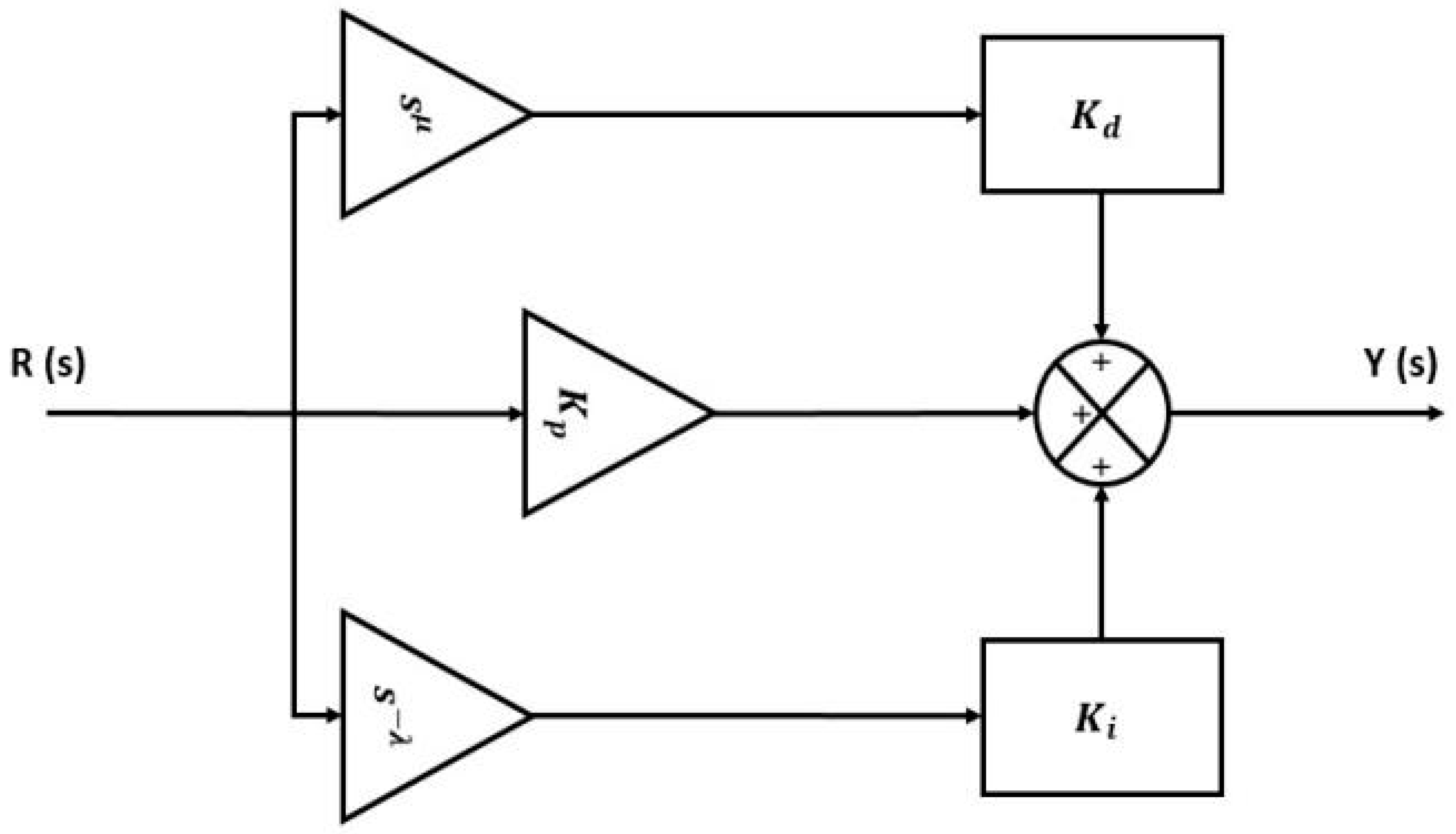
4. Tuning of FOPID Controller
The main limitation of the PI controller is that it cannot provide satisfactory control performance for systems with complex dynamics and non-linearities. In DFIG-based WECSs, the system has complex dynamics due to the presence of wind turbine dynamics, power electronics converter dynamics, and grid dynamics. The non-linear behavior of the wind turbine and converter also affect the control performance.
On the other hand, an FOPI controller is a variant of the traditional PI controller that uses fractional calculus. FOPI controllers have been shown to achieve better performance than traditional PI controllers in some applications, and they do not have the additional derivative term that is present in an FOPID. The derivative term in an FOPID controller can help provide a faster and more accurate response to changes in the system, especially in cases of non-linear systems. As the wind speed and load conditions can change rapidly in the case of a DFIG-based WECS, the system must respond quickly to maintain stability and optimal power generation.
The FOPID controller is a more advanced and flexible version of the traditional PID controller. It uses fractional calculus to improve the performance of traditional PID controllers. In the context of DFIG-based WECSs, the FOPID controller can be used in the RSC to improve the power quality of the system. It introduces three additional parameters (alpha, beta, and gamma) that allow for better tuning and control of the system. These additional parameters include the fractional order derivative and fractional order integral terms, which provide more flexibility in controlling the system dynamics. These regulate the rotor currents in a better way, which improves the power quality of the system. This helps in reducing the impact of disturbances, such as wind speed variations, on the system. In the RSC of a DFIG-based WECS, this controller can provide better control over the system’s dynamic response, transient stability and output performance. Compared with the PID controller, it has additional degree of freedom that allows it to better handle nonlinearities and uncertainties in the system. This is important in DFIG-based WECSs in which the wind turbine’s operating conditions can vary widely and quickly. It also provides better robustness against disturbances, noise, and other factors that can affect the system’s performance. The results with the FOPID controller are provided in the Results section.
Although fractional calculus is an ancient branch of mathematics, it has only recently been applied in variety of scientific and technical fields. The differential equations for the
controller in the time and frequency domains are presented in Equations (25) and (26) as:
Here,
represent the gains of the integral, derivative, and proportional components, respectively;
are the real numbers, with
The block diagram of an FOPID controller is shown in
Figure 11. The settings are changed to maximize or lower the index of performance to achieve the best CS, which is, in this case, the integral of time absolute error (ITAE), a measure of error that includes time weighting. This is defined by Equation (27) as:
The errors between the actual parameters (voltage, current, and power) and the reference parameters are represented by
respectively. The FOPID controller parameters were calculated by considering a 0.1 step change in the reference and minimizing the performance index through the use of algorithms [
28,
29,
30,
31]. The design of the fractional order PID (FOPID) controller was achieved through the minimization of the performance index, which has the property of weighing initial large errors lightly and penalizing late-occurring errors heavily. The classical tuning method was employed, which is based on trial-and-error or heuristic methods, and it was used to adjust the parameters of the controller until satisfactory performance was achieved. For an FOPID controller in the RSC of a DFIG-based WECS, the classical tuning method can be carried out using the following steps: setting the integral and derivative gains to zero, setting the proportional gain and low value, increasing the proportional gain until the system oscillates continuously, tuning the integral gain to reduce the steady-state error, tuning the derivative gain to reduce the overshoot and settling time, and finally, tuning the fractional order of the controller to improve the overall system response. The fopid_optim tool was utilized to carry out the design of the FOPID controller in which the LTI system contains the workspace name of the plant and could either be in state space or transfer function form.
The classical tuning method is used in the FOPID and PI controllers to find the values of gains. This involves determining the values of these gains using mathematical formulas that are based on the system parameters. The perturb and observe (P and O) algorithm is used for MPPT in DFIG-based WECS.
5. Analysis of the Proposed and Established Control Technique in MATLAB
The PI controller for the basic MATLAB model is shown below (
Figure 12). The classical tuning approach was used for the PI controller. The various waveforms for the same controller are shown in Figures 15–25.
The proposed FOPID controller for the DFIG-based WECS is shown in
Figure 13.
The main purpose of the FOPID controller in the RSC of DFIG-based WECS is to regulate the rotor current and voltage, which, in turn, control the speed of the generator. It improves the response of the system. By using a FOPID in the RSC, the system can achieve better control of the rotor speed and ultimately increase the energy conversion efficiency of the system. It also improves the stability of the system by regulating the reactive power of the generator, ensuring that the generator operates at a stable voltage and maintaining the stability of the grid.
The proposed BESS for the DFIG-based WECS with a PI controller is as shown in
Figure 14.
The parameters of the BESS in a DFIG-based WECS may vary depending on the system’s specific applications and requirements. Some common parameters that can be considered in a DFIG-based WECS are battery capacity, battery voltage, battery chemistry, battery management system, and charging and discharging strategies.
Here, the function of the BESS is to mitigate the effects of the intermittency and variability of wind power by storing excess energy during periods of high wind speed and supplying energy to the grid during periods of low wind speed. The controller in the BESS can regulate the charging and discharging of the battery, ensuring that the battery operates within safe and optimal operating conditions. The function of the controller in a BESS is to provide or improve the power quality of the system by reducing the total harmonic distortion (THD) of the output voltage. By using a controller in the BESS, the output voltage waveform can be made more sinusoidal, reducing THD and improving the quality of power. It also provide power quality support by regulating the voltage and frequency of the output power. The controller can respond quicky to changes in voltage and frequency, injecting and absorbing power from the grid as needed to maintain the stability of the system.
6. Results and Discussions
The various waveforms for the coefficient of performance rotor current, rotor speed, output power, i.e., stator and rotor power, bus voltage and torque are analyzed at different wind velocities in the MATLAB/Simulink and are provided below. We have taken three wind velocities of 3 m/s (less than minimum), 11 m/s (within limits), and 15 m/s (greater than maximum).
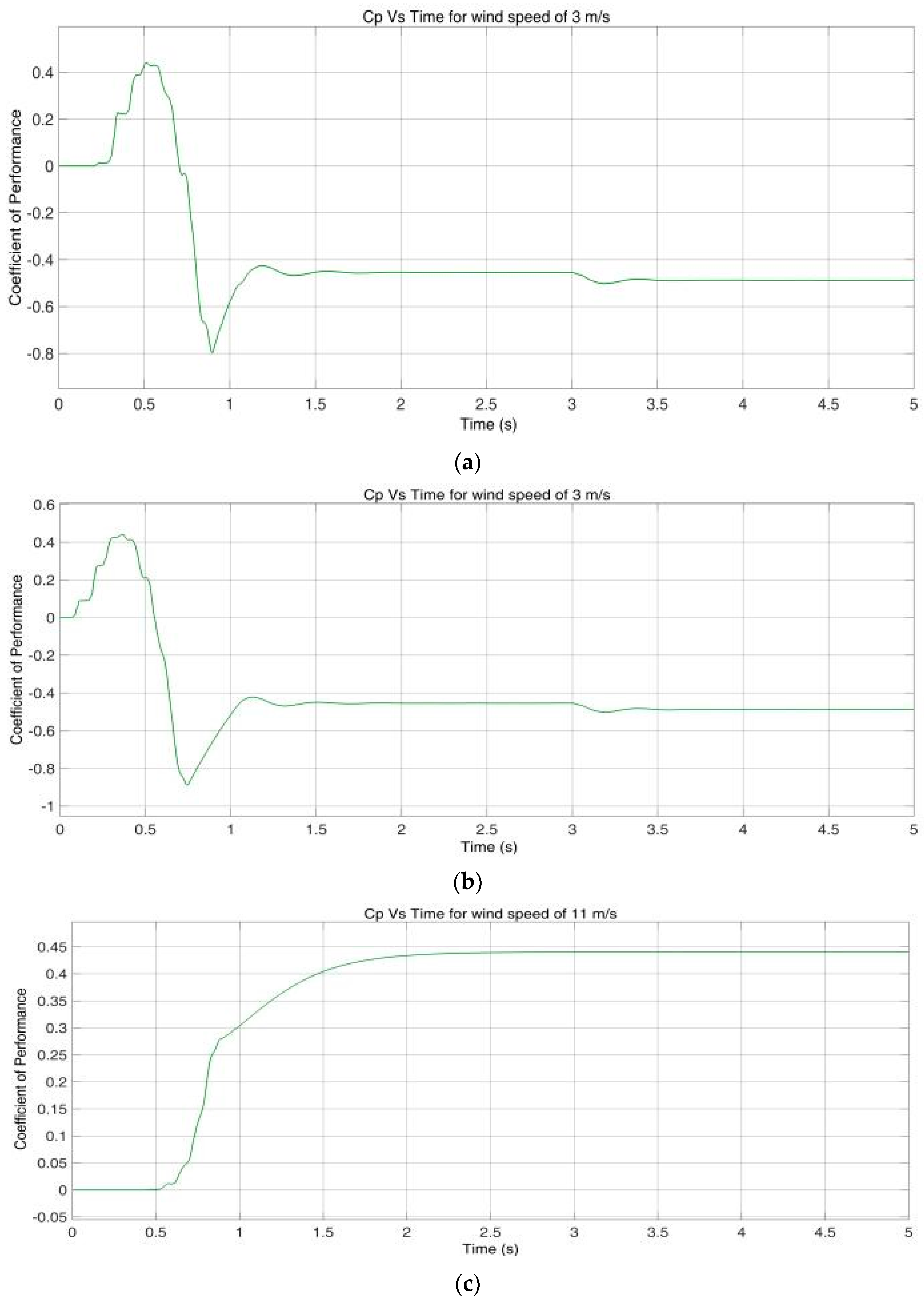
The performance coefficient
in vertical axis with respect to time (t) in the horizontal axis for a wind turbine at different wind velocities with an FOPID and a PI controller (i) at 3 m/s (ii), at 11 m/s (iii), and at 15 m/s are presented in
Figure 15a–f. The performance coefficient
is the ratio of the power captured by the rotor to the total power available in the wind (P) just before it interacts with the rotor of the wind turbine. As can be seen in
Figure 15a,b,
fluctuates when the WECS is started and has a constant value of −0.43 after some time with a wind velocity of 3 m/s. When the wind speed is further increased to 11 m/s and 15 m/s, we can then see that in
Figure 15c–f, it is around 0.44.
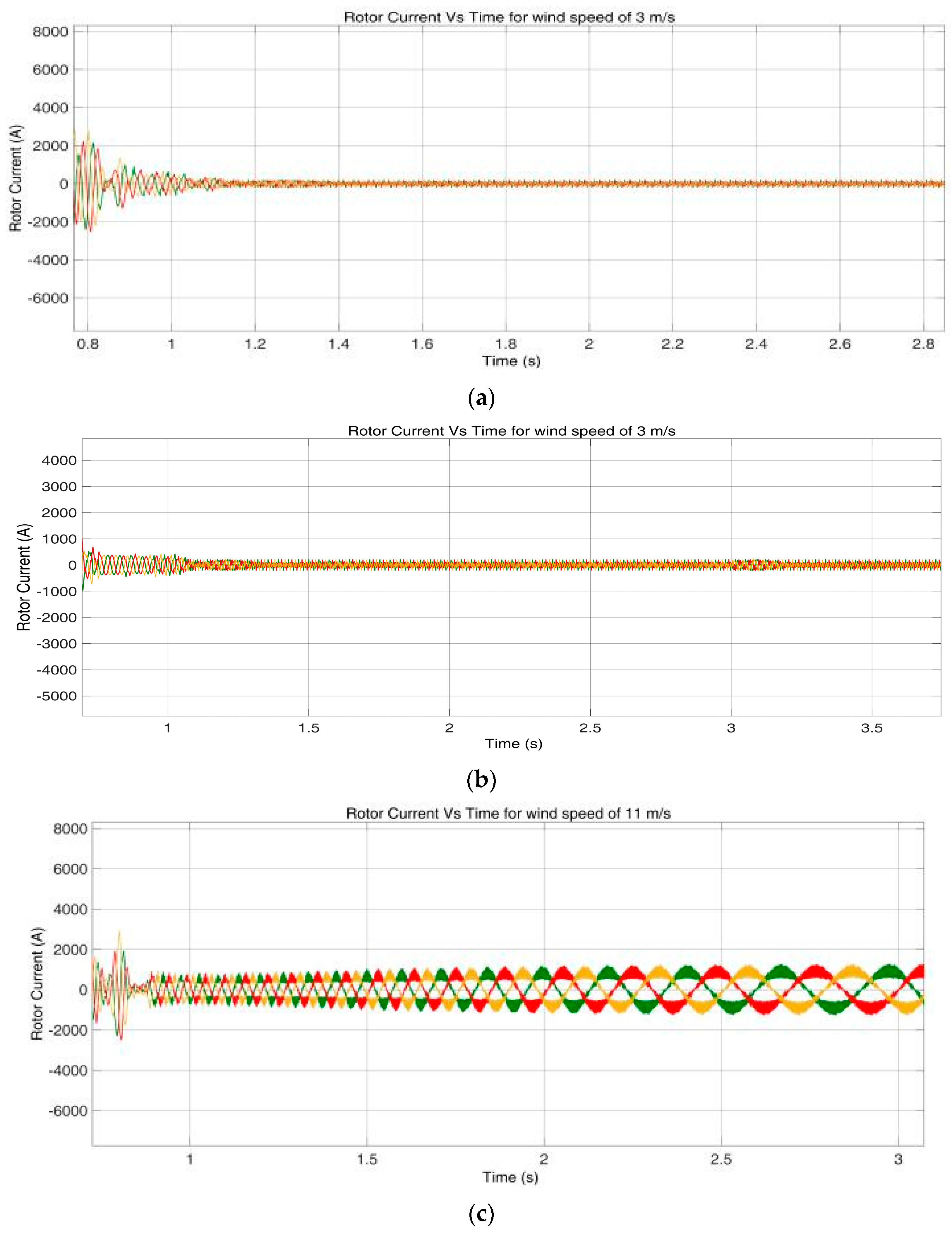
The waveforms for rotor currents in the vertical axis for three phases with respect to time in the horizontal axis for a wind turbine at different wind velocities with an FOPID and PI controller for (i) 3 m/s, (ii) 11 m/s, and (iii) 15 m/s are shown in
Figure 16a–f. In
Figure 16a,b, we can see that in the initial rotor current is not sinusoidal; however, after some time, it has a sinusoidal waveform. The magnitude of the current is significantly lower with a PI controller but increases slightly with the FOPID controller, whereas in
Figure 16c–f, the rotor currents are, once again, initially not sinusoidal, but the magnitude of the rotor currents is high with the FOPID controller.
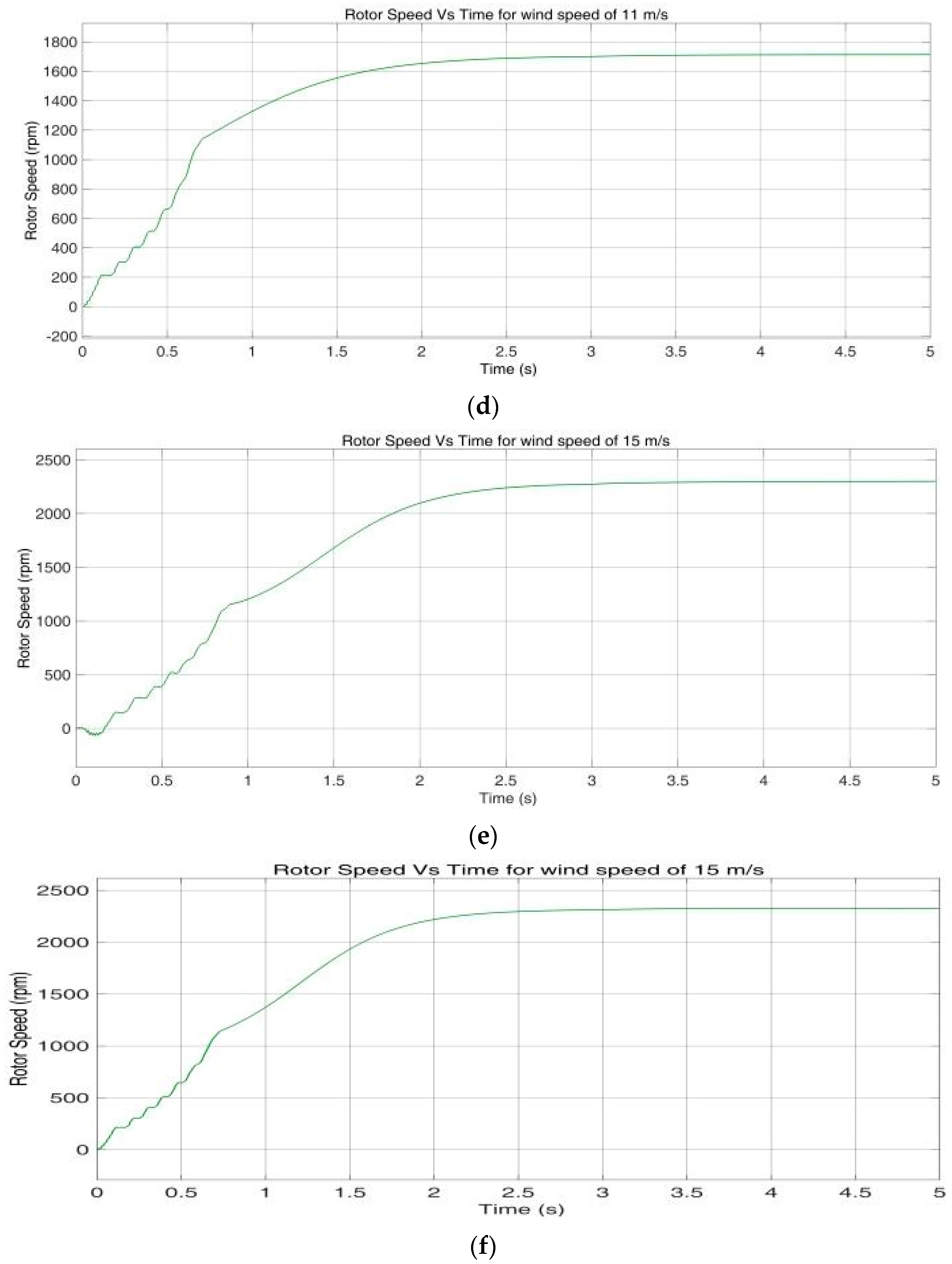
The waveforms for rotor speed in the vertical axis with respect to time in the horizontal axis for a wind turbine at different wind velocities with an FOPID and PI controller for (i) 3 m/s, (ii) 11 m/s, and (iii) 15 m/s are shown in
Figure 17a–f. In
Figure 17a,b, we can see that at a wind velocity of 3 m/s, the speed of the rotor slowly increases and reaches up to 950 rpm after some time; in
Figure 17c,d, at a wind velocity of 11 m/s, the rotor speed slowly increases and reaches up to 1750 rpm after some time; in
Figure 17e,f, at a wind velocity of 15 m/s, the rotor speed slowly increases and reaches up to 2250 rpm.
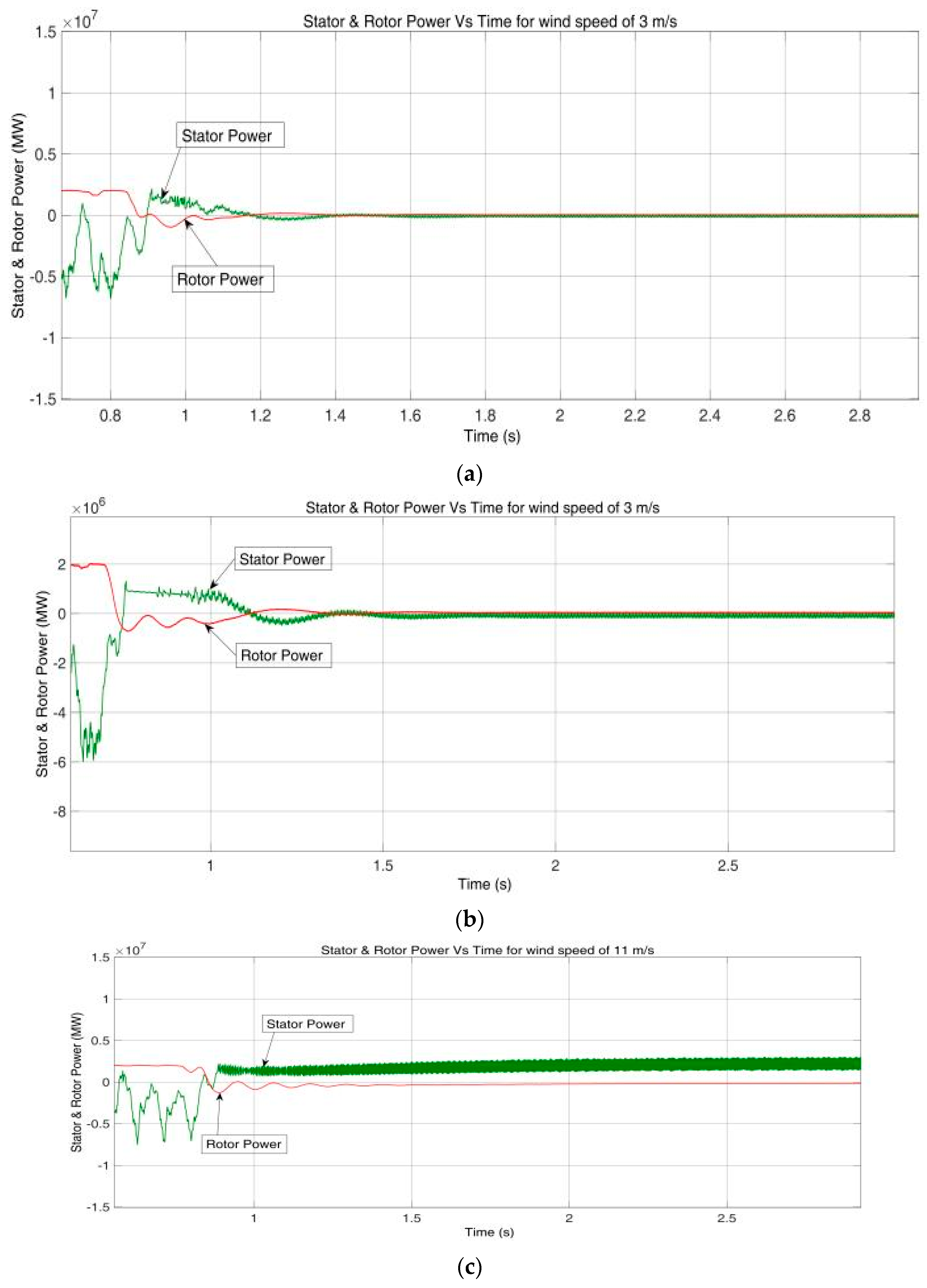
The stator and rotor power in the vertical axis with respect to time in the horizontal axis for a wind turbine at different wind velocities with an FOPID and PI controllers for (i) 3 m/s, (ii) 11 m/s, and (iii) 15 m/s are shown in
Figure 18a–f. The red color indicates the real stator power and pink color indicates the real rotor power. As can be seen in
Figure 18a,b, at a wind velocity of 3 m/s, the stator power and rotor power delivered by the wind turbine are very low, of the orders of 0.1 MW and 0.2 MW, respectively, because the wind speed is low; in the initial phase, it fluctuates and begins to increase as it achieves its speed. The rotor power is high because the BESS supplies power to the grid during low-wind-speed periods. In
Figure 18c,d, at a wind velocity of 11 m/s, we can see that the power developed by the stator and the power developed by the rotor are around 2 MW and zero, respectively, because at this point, the rotor is not supplying any power and all the real power is received across the stator. In
Figure 18e,f, the power developed is around 2.5 MW; as the wind velocity is 15 m/s at this time, the excess power is stored in the BESS.
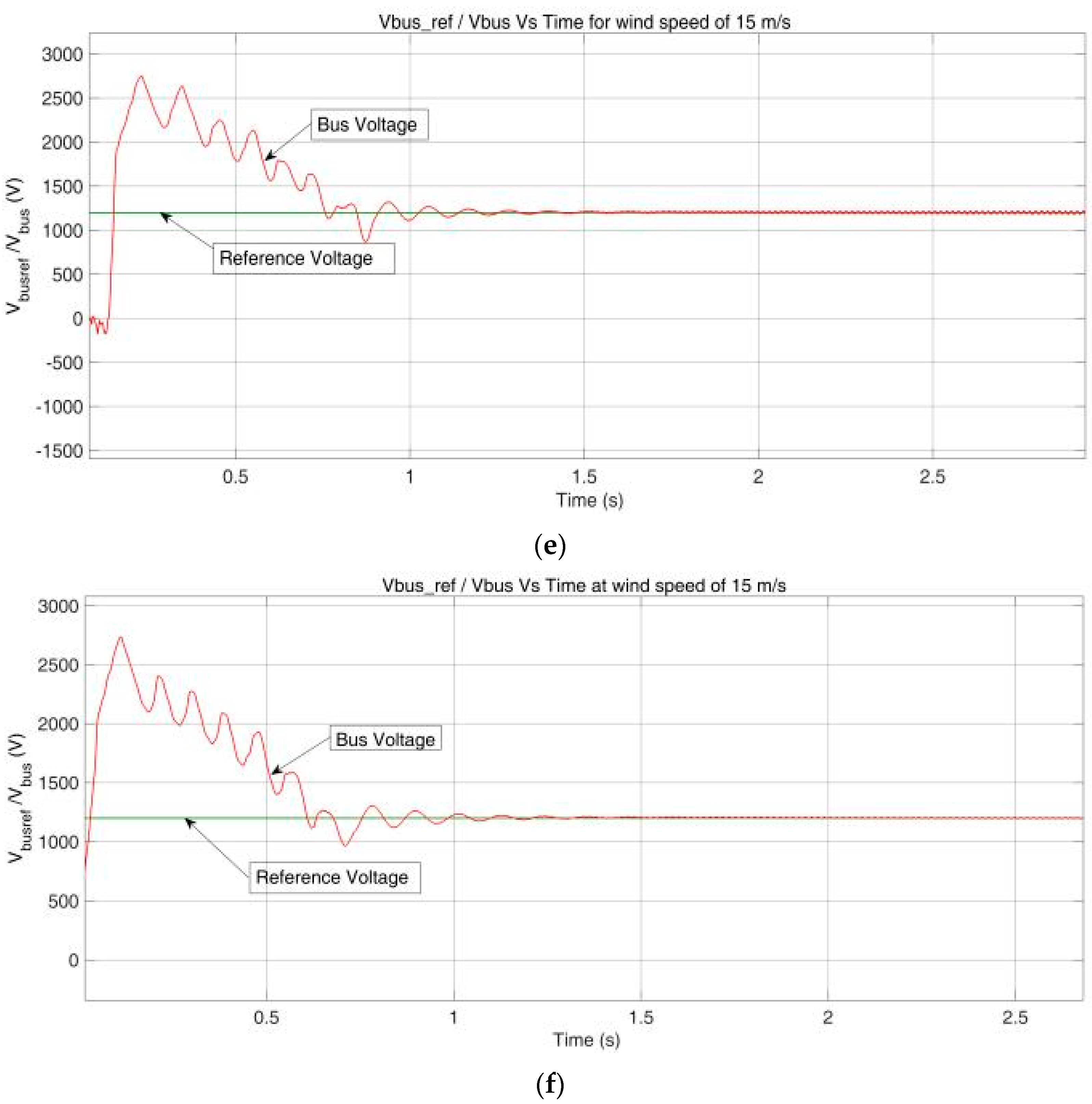
The bus voltage
in the vertical axis at the DC link with respect to time (t) in the horizontal axis for a wind turbine at different wind velocities with an FOPID and PI controllers for (i) 3 m/s, (ii) 11 m/s, and (iii) 15 m/s are shown in
Figure 19a–f. As we can see in
Figure 19a–f, the bus voltage is received at the DC link and is almost constant for all wind velocities. This is because the BESS is always connected in the system, and it supplies power to the grid during periods of low wind velocity. When there are wind gusts, it stores the excess power in the BESS.
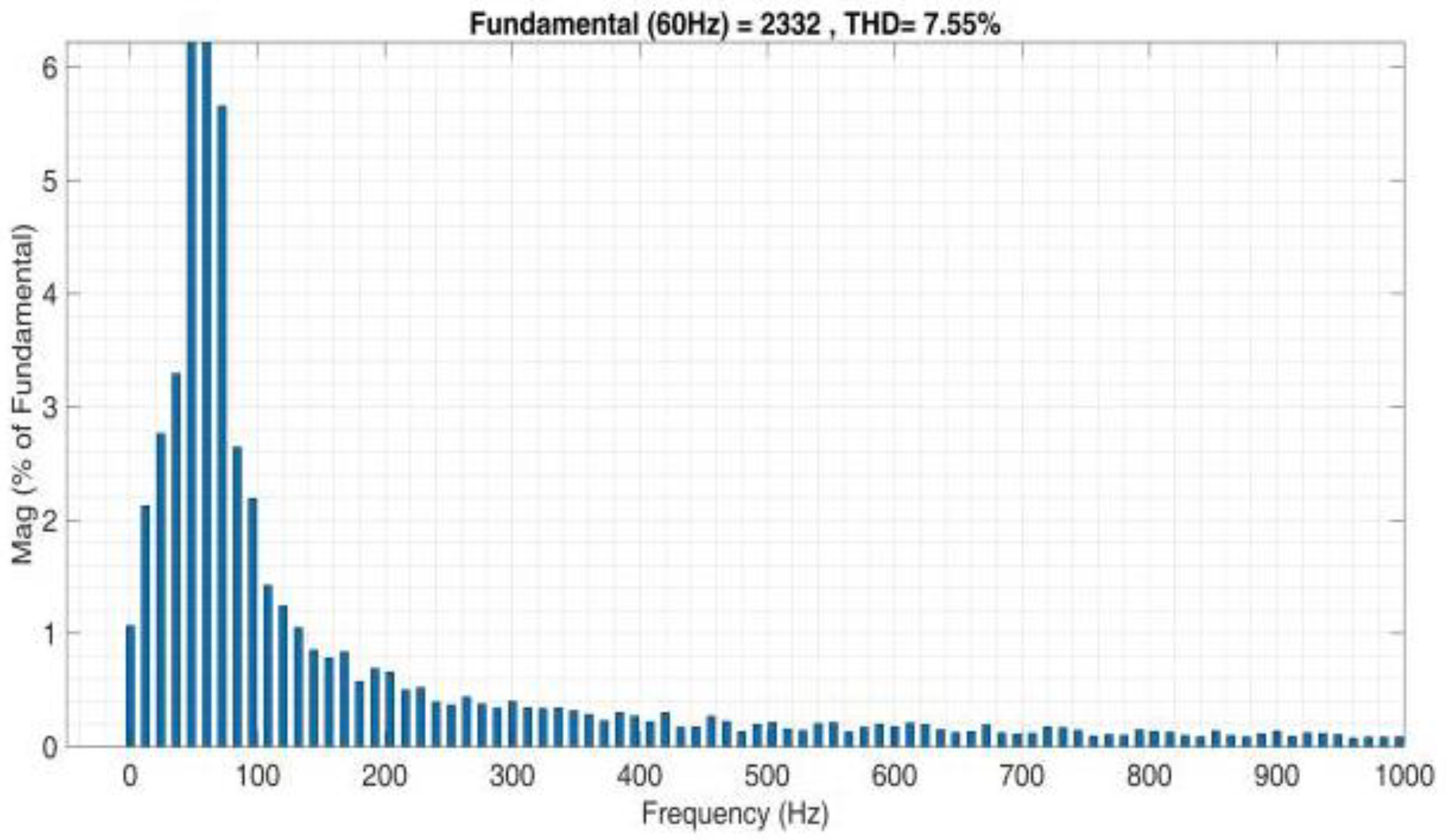
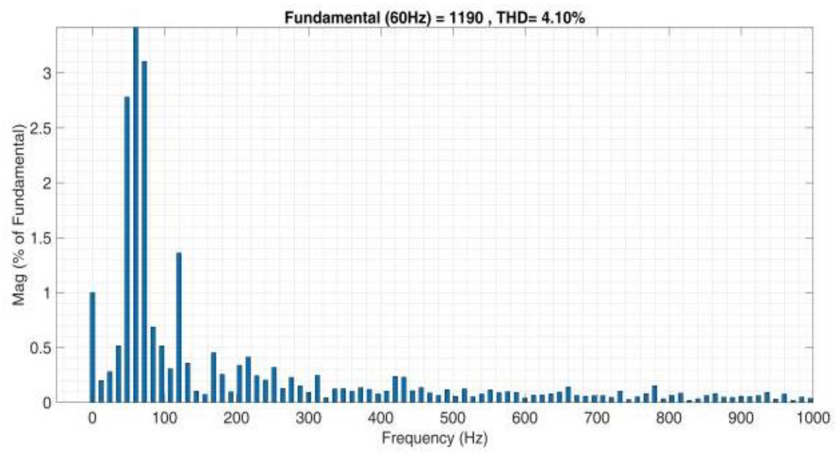
From
Figure 20,
Figure 21,
Figure 22,
Figure 23,
Figure 24 and
Figure 25, it can be seen that the FFT analysis was performed for the rotor current with an FOPID controller and PI controller. From the FFT analysis, it can be observed that with the FOPID, the THD was improved when compared with the PI controller at same wind speeds. The FOPID provides a major contribution to the power quality in a DFIG-based WECS. We can see that the with the FOPID controller, performance was improved at all wind speeds, and it can further be improved by providing the BESS with some new control algorithms.
Implementing the model in a practical way involves designing the control algorithms (PI, FOPID, FL, and ANFIS) and tuning the controller parameters to achieve the desired performance, hardware selection, and simulation; this involves obtaining appropriate hardware components for the BESS and RSC, i.e., selecting the battery type and capacity for the BESS and selecting the power electronics components (IGBTs, capacitors, and inductors) for the RSC. The next step is to design the circuitry for the BESS and RSC, which involves designing a battery management system (BMS) for the BESS and designing the power electronics circuitry for the RSC. The next step is the development of a prototype, which involves assembling hardware components and circuitry according to the design. The last step is to test and validate the prototype, which involves conducting experiments and taking measurements to verify that the BESS and RSC are functioning as expected and that the prototype meets the desired performance criteria. For the low-power scale, it has a lower efficiency, which results in increased losses and decreased power generation. It also requires larger generators and power electronics converters, and it has a high cost and complex grid integration, which makes it less suitable for low-power applications.
7. Conclusions
In the proposed work, we have introduced the utilization of an FOPID controller with five system variables which has been shown to be more efficient than conventional controllers in several areas. The FOPID which was used to execute the suggested controllers within the RSC, whichwas implemented using the FOPID and the fractional order PID controller block from the Fractional-Order Modeling and Control (FOMCON) toolbox, which was used for simulation purposes. fopid_optim is a Simulink toolbox that was used to optimize the FOPID controller. The purpose of the controller is to automatically regulate the rated power of a 2 MW wind turbine generation system in response to varying wind speeds. The WECS consisted of a WT and a DFIG with a BESS incorporated into the DC link with an initial SOC of 71.2%. The BESS stores energy when the wind speed exceeds the MPPT threshold and supplies voltage to the grid through the GSC when the wind speed falls below the MPPT. A simple PI controller was used instead of a conventional controller to increase the storing and releasing charge rate of the battery. The simulation findings were developed in a MATLAB/Simulink environment with validated parameters for the WT and generator. The various waveforms shown in
Figure 14,
Figure 15,
Figure 16,
Figure 17 and
Figure 18 are from MATLAB/Simulink software, such as the performance coefficient of the WT, stator power, rotor power, rotor current, DC bus voltage through the DC link, and the speed of the rotor at multiple wind velocities of 5 m/s, 11.2 m/s, and 15 m/s. The performance coefficient of the WT exhibits fluctuations during start-up and periods of low wind speeds, while the rotor speed and the output power at the rotor and stator increase. There is a slight increase in the voltage at the DC link terminal when the wind velocity is high. The study was conducted using the parameters shown in
Table 1, with a fluctuating wind velocity applied to the WECS, and various parameters for the BESS are shown in
Table 2.
Every controller we used has its own advantages and limitations. The FO-PID controller has a complex control strategy, higher computational requirements, non-linear behavior, a high sensitivity to parameter variations, and difficulties in physical implementation. On the other hand, we used a PI controller in the BESS, which had certain limitations such as its limited control, poor dynamic control, sensitivity to load changes, fixed tuning parameters, sensitivity to model uncertainties, difficulty in tuning, and limited capability.
In the future, to address the limitations of FOPID controllers, we can improve the design and tuning processes of the FOPID controllers and reduce their computational requirements. Some new control techniques are being explored that may offer improved performance in specific situations. For BESS control, we can also use advanced control techniques that can provide better control over the BESS. On the other hand, the use of advanced sensors and communication systems can help improve the accuracy and responsiveness of the control system.


 and
and 


