Article

A Novel Kinematics Model of Flip-Flow Screen Panel: Inclined Catenary Model

1
School of Mechanical and Electrical Engineering, Henan Technical Institute, Zhengzhou 450042, China
2
School of Mechanical and Power Engineering, Zhengzhou University, Zhengzhou 450001, China
3
Xinxiang Gaofu Machinery Co., Ltd., Xinxiang 453000, China
*
Authors to whom correspondence should be addressed.
Mathematics 2023, 11(9), 2028; https://doi.org/10.3390/math11092028
Submission received: 25 March 2023 / Revised: 21 April 2023 / Accepted: 23 April 2023 / Published: 25 April 2023
(This article belongs to the Special Issue Mathematical Modeling and Numerical Analysis for Applied Sciences)

Abstract

:
A flip-flow screen can effectively screen viscous particles, and its kinematic characteristics determine its screening performance. Since previous kinematic models have errors, a novel kinematics model of the flip-flow screen panel, namely the inclined catenary model, is developed. It is verified by comparing theoretical motion trajectory with experimental motion trajectory. Then, the kinematic characteristics, i.e., displacement, velocity and acceleration, obtained using four kinematic models, are compared. Finally, the effects of rotation speed n, eccentricity e, incline angle α and tensional amount Δl on displacement, velocity and acceleration of the midpoint are investigated. The results show that displacement, velocity and acceleration of each point in the screen panel can be calculated by using the inclined catenary model, and the inclined catenary model possesses higher prediction accuracy than the three previous kinematic models. Moreover, with the increase in n, the absolute value of velocity and acceleration increases, and the maximum absolute value of displacement remains unchanged. With the increase in e, the absolute value of displacement, velocity and acceleration increases. With the increase in α, the absolute value of transverse components of displacement, velocity and acceleration increases slowly and the absolute value of longitudinal components of displacement, velocity and acceleration decreases slightly. With the increase in Δl, the absolute value of displacement, velocity and acceleration increases. Therefore, the inclined catenary model can provide good guidance for selecting reasonable screening parameters.

1. Introduction

Viscous particles, such as moist coal and organic fertilizer, not only easily agglomerate together, but also easily adhere to and block screen apertures, so they are difficult to screen [1]. However, a flip-flow screen can provide agglomerated particles with high velocity and high acceleration for depolymerization and separation from the screen surface, and so effectively screen viscous particles [2,3]. Thus, its kinematic characteristics, i.e., displacement, velocity and acceleration, determine its screening performance [4,5,6].
For investigating the effects of screening parameters on the kinematic characteristics, different kinematic models of the flip-flow screen panel, such as the simplified geometric model, the elastic compressed bar model, the bending beam deflection model, the string vibration model and the catenary model have been established. Because it possesses simplicity, the simplified geometric model is commonly used. Zhang et al. [7] establish a simplified geometric model of the flip-flow screen panel for analyzing the midpoint kinematic characteristics. The results show that displacement, velocity and acceleration change periodically. Zou et al. [8] use the simplified geometric model of the flip-flow screen for investigating the effects of the tensional amount Δl. The results show that with the increase in Δl, displacement decreases, while velocity and acceleration increase. Li et al. [9,10] establish a simplified geometric model of a flip-flow screen panel with a crankshaft-link structure. The results show that this model can describe the kinematic characteristics with a maximum error of 6.96%. It can be seen that the simplified geometric model has some error because it is oversimplified.
Meanwhile, other kinematic models are also used. Zhao et al. [11] and Peng et al. [12,13] consider the flip-flow screen panel as an elastic compressed bar and then establish an elastic compressed bar model. The results show that displacement increases with the increase in n and with the decrease in Δl, while the maximum error between the experimental and theoretical data reaches 6.786%. Zuber et al. [14] consider the flip-flow screen panel as a bending beam and then establish a bending beam deflection model, by which displacement, velocity and acceleration of each point can be obtained. Chen et al. [15] simplify the vibration of the screen panel into a string vibration model and then establish a string kinematic model, by which the axial and lateral displacement of each point can be obtained, while the maximum error of the amplitude reaches 16.1%.
All the above models have some errors because the flip-flow screen panel is long and soft and is close to a catenary. So based on the catenary theory, Xiong et al. [16] establish a horizontal catenary model of the flip-flow screen panel for investigating the effects of rotational speed n, incline angle α and tensional amount Δl. The results show that displacement, velocity and acceleration increase with the increase on n and with the decrease in α and Δl. However, in this model the screen panel is assumed to be horizontal, which is inconsistent with the actual situation, as the flip-flow screen panel actually adopts an incline.
Therefore, a novel kinematic model of the flip-flow screen panel, namely the inclined catenary model, is developed. It is verified by comparing theoretical motion trajectory with experimental motion trajectory. Then, the kinematic characteristics obtained using the inclined catenary model, i.e., displacement, velocity and acceleration of the midpoint are compared with three previous kinematic models. Finally, the effects of rotation speed n, eccentricity e, incline angle α and tensional amount Δl are investigated.

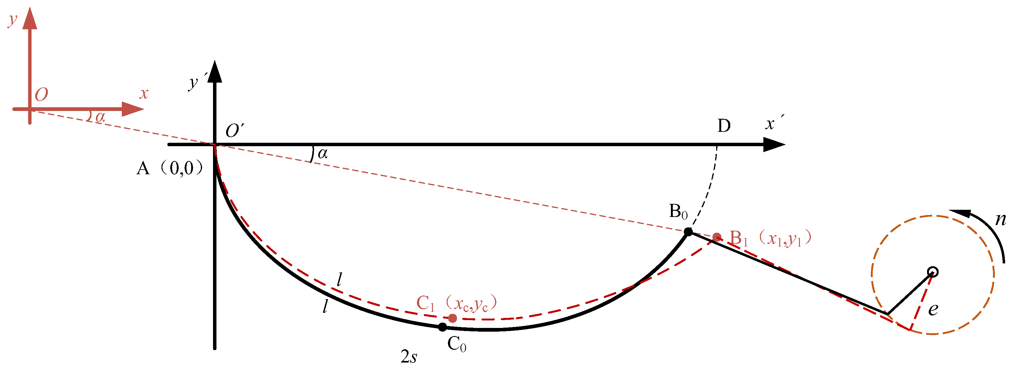
2. Mathematical Model

Figure 1 shows the schematic diagram of the inclined catenary model. In it, arc AD is a catenary curve representing the screen in its horizontal position, arc AB0 represents the screen in its inclined position at any moment, and arc AB1 represents the screen at the next moment. Point A is set to be fixed, and Point B moves left and right. The incline angle is α, n is the rotation speed and e is the eccentricity.
The curve equation of arc AB is expressed as:
y = a cosh ( x a + b ) + c
In Equation (1), a, b and c are three unknown variables, which can be solved with three nonlinear equations.
According to the coordinates of point A and point B1, Equations (2) and (3) can be obtained.
0 = a cosh ( b ) + c
y 1 = a cosh ( x 1 a + b ) + c
The coordinate of point B1 (x1, y1) is related to movement of the screen panel, so Equation (4) is obtained.
{ x 1 = 2 [ s e ( 1 cos ( ω t ) ) ] cos α y 1 = 2 [ s e ( 1 cos ( ω t ) ) ] sin α
where ω = 2πn is the rotation angular velocity, and s is a half of the length of arc AB, which can be expressed as:
2 s = 0 x 1 1 + y 2 d x
After calculation, Equation (6) can be achieved.
2 s = a sinh ( x 1 a + b ) a sinh ( b )
Then, a, b and c can be calculated by solving simultaneous Equations (3), (4) and (6), and then the Equation (1) is also obtained.
Suppose an arbitrary point C1 in arc line AB1, and l represents the length of arc AC1. Then, the transverse coordinate xc of point C1 satisfies Equation (7).
l = a sinh ( x c a + b ) a sinh ( b )
After calculation, xc can be obtained, as shown in Equation (8).
x c = a ln [ l + sinh ( b ) a + ( l + sinh ( b ) a ) 2 + 1 ] a b
Then, the longitudinal coordinate yc of point C1 can also be obtained by solving simultaneous Equations (1) and (8).
y c = a cosh ( x c a + b ) + c
In Equations (8) and (9), the coordinates of point C1 are obtained under the assumption that point A is fixed. However, in fact point A can move and its absolute coordinate is:
{ x a = e ( 1 cos ( ω t ) ) cos α y a = e ( 1 cos ( ω t ) ) sin α
Therefore, Equations (8) and (9) are revised and the absolute coordinate of point C1 at time t is expressed as:
{ x c a = a ln [ l + sinh ( b ) a + ( l + sinh ( b ) a ) 2 + 1 ] a b + e ( 1 cos ( ω t ) ) cos α y c a = a cosh ( x c a + b ) + c e ( 1 cos ( ω t ) ) sin α
When t = 0, xca and yca become the absolute coordinate of point C1 at t = 0. After comparing the absolute coordinate at time t and at t = 0, the transverse displacement sxc and the longitudinal displacement syc of point C1 can be obtained. Then, the total displacement sc of point C1 can be calculated with the equation below.
s c = s x c 2 + s y c 2
Then, the transverse velocity vxc, transverse acceleration axc, longitudinal velocity vyc and longitudinal acceleration ayc of point C1 can be calculated with derivation. Finally, the total velocity vc and the total acceleration ac of point C1 can be calculated and expressed as:
v c = v x c 2 + v y c 2
a c = a x c 2 + a y c 2

3. Results and Discussion

3.1. Verification of the Inclined Catenary Model

For verifying the inclined catenary model, translational motion experiments are conducted using a hyperelastic polyurethane screen panel with the dimension of 250 × 150 × 5 mm, as shown in Figure 2.
Meanwhile, translational motion simulation is also conducted using RecurDyn software [17], as shown in Figure 3. The Mooney–Rivlin Material model is adopted to simulate hyperelastic characteristics with strain rates up to 200%, which is expressed as:
W = C 1 ( I ¯ 1 3 ) + C 2 ( I ¯ 2 3 ) + 1 d ( J 1 ) 2
where W is potential energy of strain, I ¯ 1 is the first order invariant of the deformation tensor, I ¯ 2 is the second order invariant of the deformation tensor, d is incompressible parameter and J is volumetric ratio. In this study, C1 = 0.46 MPa, C2 = 0.12 MPa. In addition, Poisson’s ratio is 0.499, density is 1200 kg/m3 and shear modulus is 1.157 × 10⁹ Pa.
As shown in Figure 3, a screen panel with the same dimension is meshed with Solid8 (Hexa8). Finally, 15,453 nodes and 7828 elements are obtained. The translational motion pairs are applied to both sides. The computation time is set to 1.5 s.
Both experiment and simulation of translational motion are carried out at n = 200 r/min, α = 20° and Δl = 0 mm. Eccentricity e is set to 6 mm, so slack amount (i.e., reduction of the linear distance between the two ends) can change from 0 to 12 mm. Then, the trajectory of the screen is measured under different slack amounts and compared with that calculated with the inclined catenary model and the elastic compressed bar model, as shown in Figure 4 and Table 1.
As the slack amount increases from 0 to 12 mm, the screen panel drops slowly. Obviously, two theoretical motion trajectories and the simulation motion trajectory have the same trend as the experimental motion trajectory. However, the elastic compressed bar model has a large error, which increases with the increase in the slack amount and reaches 4.5 mm when the slack amount is 12 mm. Conversely, the theoretical motion trajectory obtained with the inclined catenary model agrees well with both the simulation motion trajectory and the experimental motion trajectory, and the maximum error does not exceed 1.5 mm, which verifies a higher trajectory prediction accuracy of the inclined catenary model.

3.2. Comparison of Four Kinematic Models

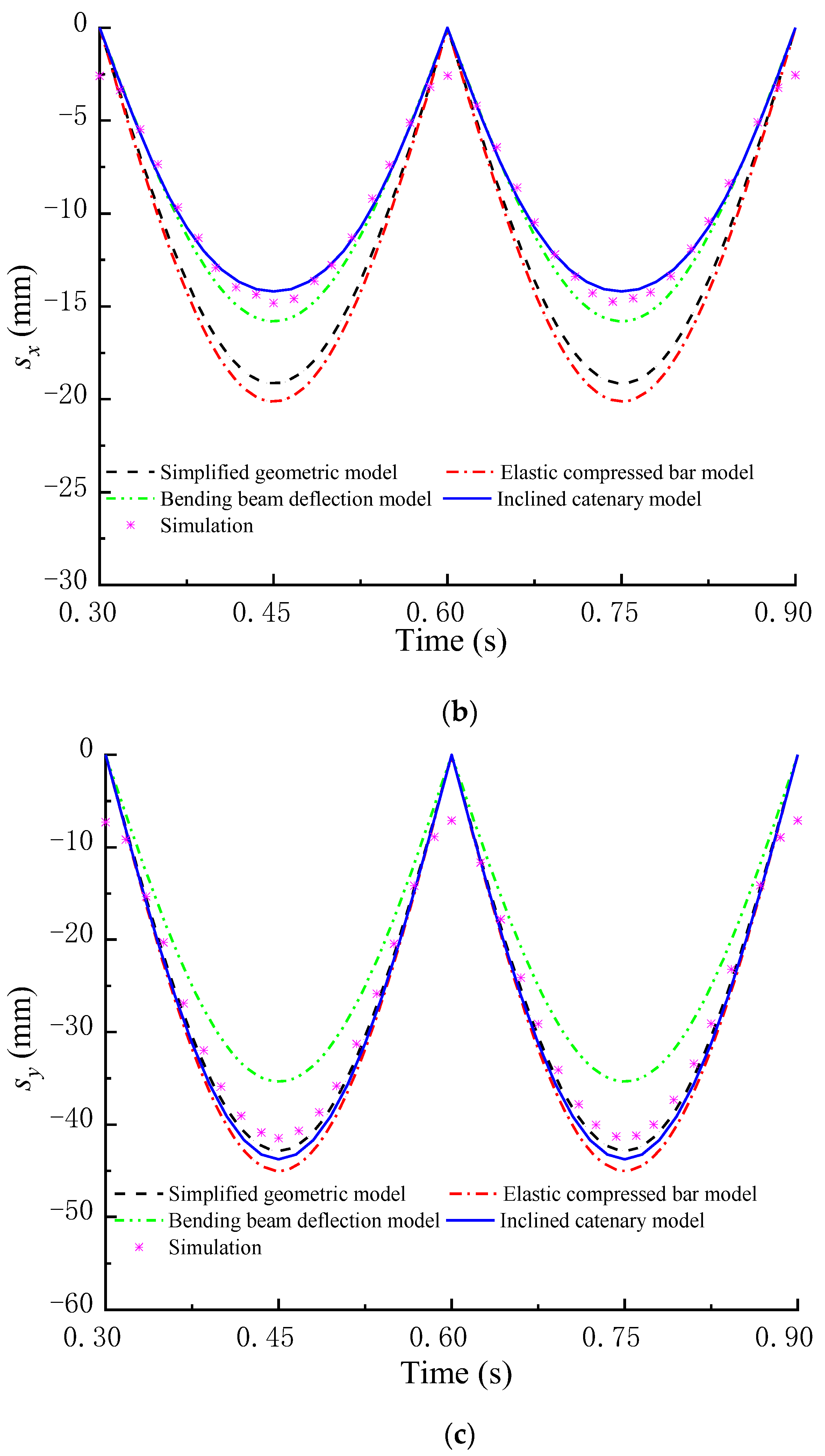
3.2.1. Comparison of Displacement

Figure 5 shows the midpoint displacement of the screen panel achieved using four theoretical models. The total displacement s, the transverse displacement sx and the longitudinal displacement sy go down and up periodically, which is approximately parabolic. Although possessing the same trend, the four theoretical models have different errors, as shown in Table 2. Compared with the simulation displacement, s calculated using the bending beam deflection model and the elastic compressed bar model has larger errors, sx calculated with the simplified geometric model and the elastic compressed bar model has larger errors, and sy achieved with bending beam deflection model has larger errors. However, all of s, sx and sy calculated with the inclined catenary model always agree well with the simulation displacement, which verifies a higher displacement prediction accuracy of the inclined catenary model.

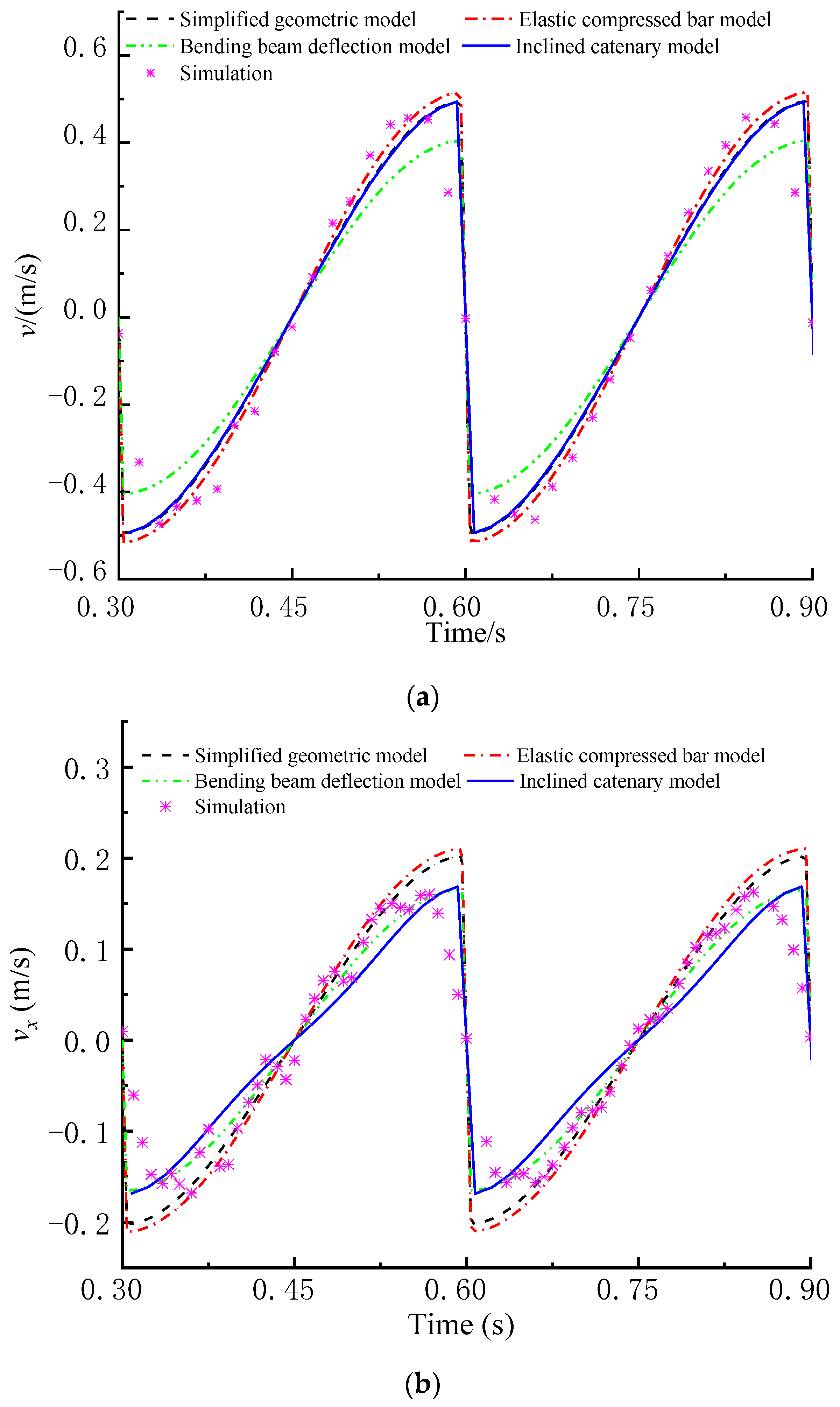
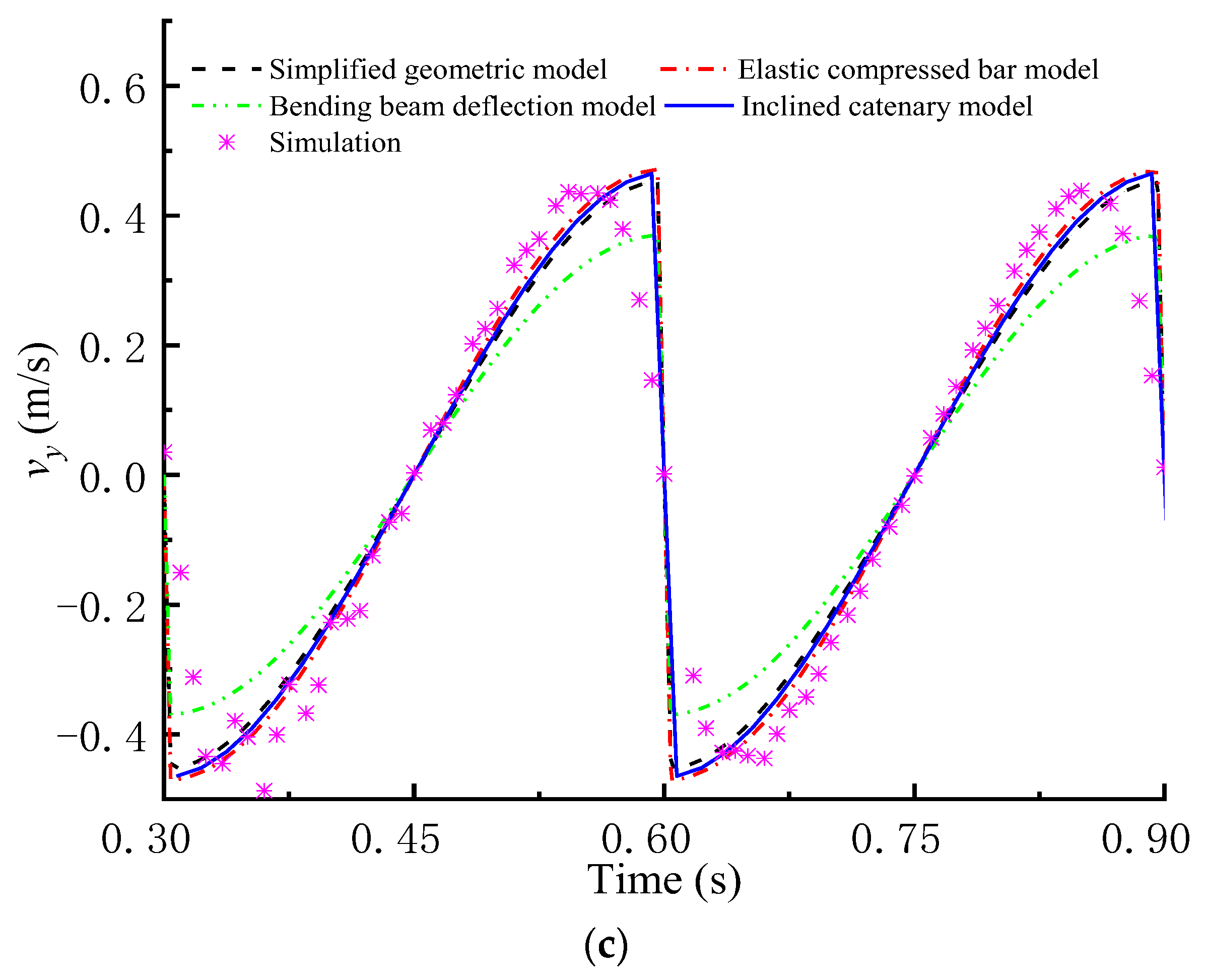
3.2.2. Comparison of Velocity

Figure 6 shows the midpoint velocity of the screen panel achieved with four theoretical models. The total velocity v, the transverse velocity vx and the longitudinal velocity vy all first rise slowly and then fall sharply, indicating that the velocities are discontinuous. Although possessing the same trend, the four theoretical models have different errors, as shown in Table 3. Compared with the simulation velocity, v achieved using the bending beam deflection model has larger errors, vx calculated with the simplified geometric model and the elastic compressed bar model has larger errors, and vy calculated with the bending beam deflection model has larger errors. However, all of v, vx and vy calculated with the inclined catenary model always agree well with the simulation velocity, which verifies a higher velocity prediction accuracy of the inclined catenary model.

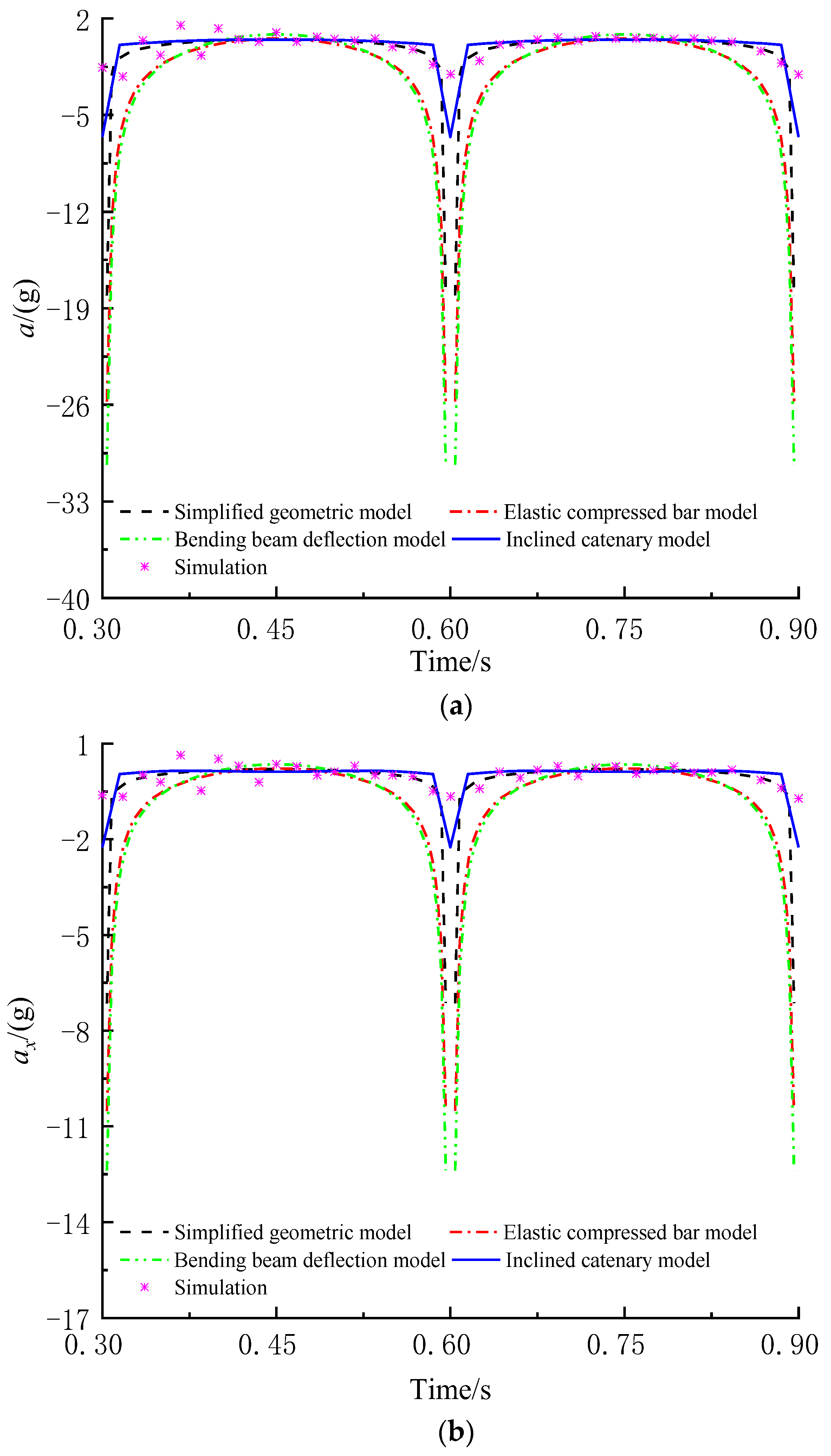
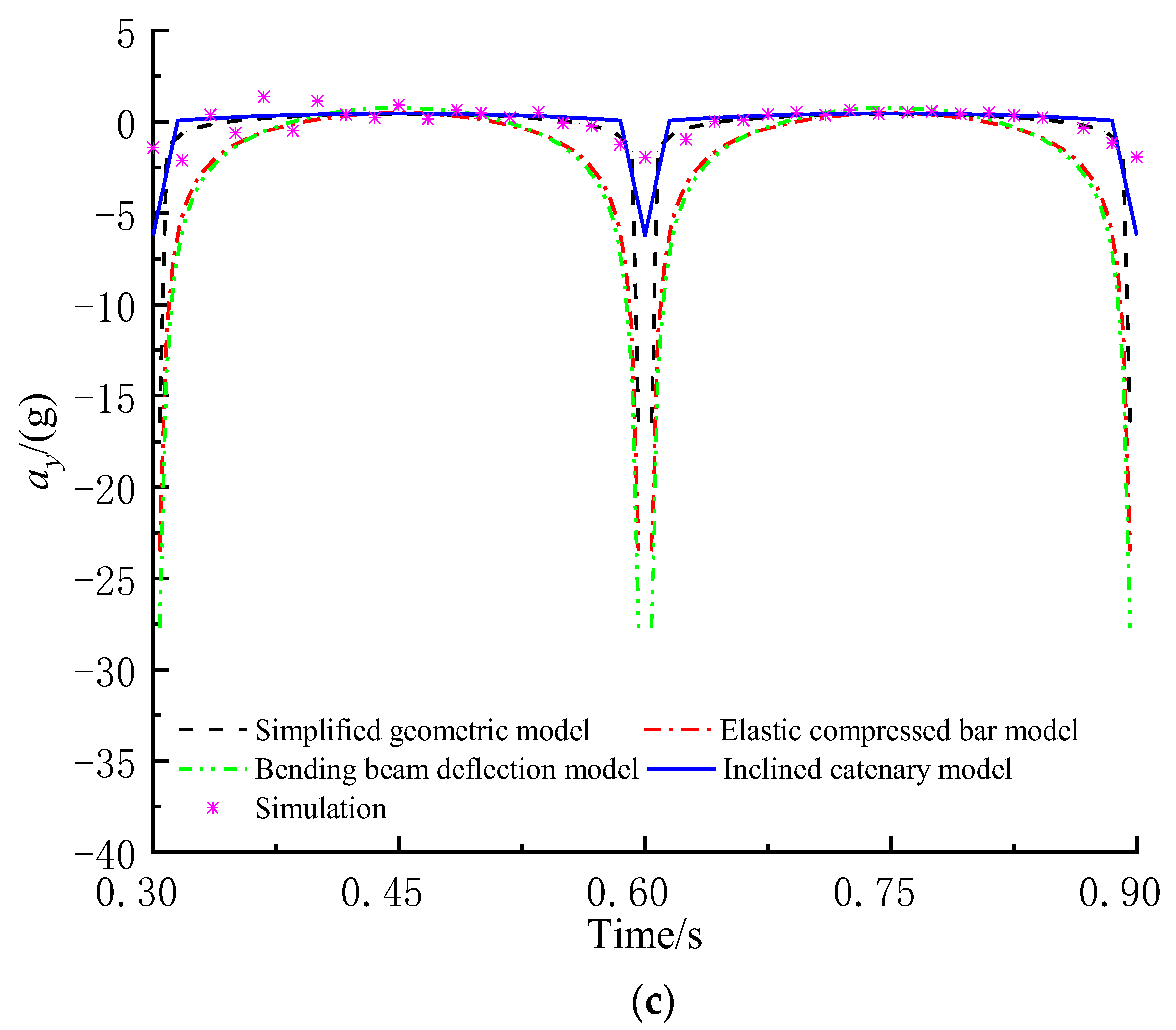
3.2.3. Comparison of Acceleration

Figure 7 shows the midpoint acceleration of the screen panel achieved using four theoretical models. The total acceleration a, the transverse acceleration ax and the longitudinal acceleration ay are small in most of a period, while they change sharply in the time between two adjacent periods. Although possessing the same trend, the four theoretical models have different errors, as shown in Table 4. Compared with the simulation acceleration, all of a, ax and ay achieved with the simplified geometric model, the bending beam deflection model and the elastic compressed bar model always have much larger errors, which even approach infinity at time between two adjacent periods. However, all of v, vx and vy calculated with the inclined catenary model always agree well with the simulation acceleration, which verifies a higher acceleration prediction accuracy of the inclined catenary model.
Overall, the inclined catenary model possesses higher prediction accuracy for displacement, velocity and acceleration of the flip-flow screen panel than other kinematic models.

3.3. Effects of n, e, α and Δl on Kinematic Characteristics

From Equation (11), it is concluded that the kinematic characteristics of screen panel are mainly affected by n, e, α and Δl, so the effects of these screening parameters are investigated based on the inclined catenary model. According to reference [2,7,8,11], the reasonable range is selected as follows: n, e, α and Δl are 200~650 r/min, 2~8 mm, 10°~25° and −6~0 mm, respectively.

3.3.1. Effect of Rotation Speed n

When α, Δl and e are 20°, 0 mm and 6 mm, respectively, displacement, velocity and acceleration of the midpoint change with n, as shown in Figure 8. Additionally, s, sx and sy are all W-shaped, and the absolute value of sy is always slightly smaller than that of s and is always larger than that of sx. With the increase in n, the period of s, sx and sy becomes short, while the maximum absolute value of s, sx and sy remains unchanged. Similarly, v, vx and vy are all N-shaped, and the absolute value of vy is always slightly smaller than that of v and is always larger than that of vx. With the increase in n, the period of v, vx and vy become short, and the absolute value of v, vx and vy increases. In addition, a, ax and ay are all umbrella-shaped, and the absolute value of ay is always slightly smaller than that of a and is always larger than that of ax. With the increase in n, the period of a, ax and ay become short, and the absolute value of a, ax and ay increases rapidly.
Overall, with the increase in n, the period of displacement, velocity and acceleration becomes short, the absolute value of velocity and acceleration increases, and the maximum absolute value of displacement remains unchanged. Moreover, large n will lead to short screening time and small n will lead to low vibration intensity, both of which are unfavorable to high screening efficiency and large flow rate of viscous particles. So, a reasonable n should be selected for both enough screening time and high vibration intensity.

3.3.2. Effect of Eccentricity e

When n, α and Δl are 500 r/min, 20° and 0 mm, respectively, displacement, velocity and acceleration of the midpoint change with e, as shown in Figure 9. In addition, s, sx and sy are still W-shaped, and the absolute value of sy is still slightly smaller than that of s and is still larger than that of sx. With the increase in e, the period of s, sx and sy remains unchanged, while the absolute value of s, sx and sy increases, especially s and sy. Additionally, v, vx and vy are still N-shaped, and the absolute value of vy is still slightly smaller than that of v and is still larger than that of vx. With the increase in e, the period of v, vx and vy remains unchanged, and the absolute value of v, vx and vy increases, especially v and vy. In addition, a, ax and ay are still umbrella-shaped, the absolute value of ay is still slightly smaller than that of a and is still larger than that of ax. With the increase in e, the period of a, ax and ay remains unchanged, and the absolute value of a, ax and ay increases, especially a and ay.
Overall, with the increase in e, the absolute value of displacement, velocity and acceleration increases. Moreover, large e will lead to short screening time and small e will lead to low vibration intensity, both of which are unfavorable to high screening efficiency and large flow rate of viscous particles. So, a reasonable e should be selected for both enough screening time and high vibration intensity.

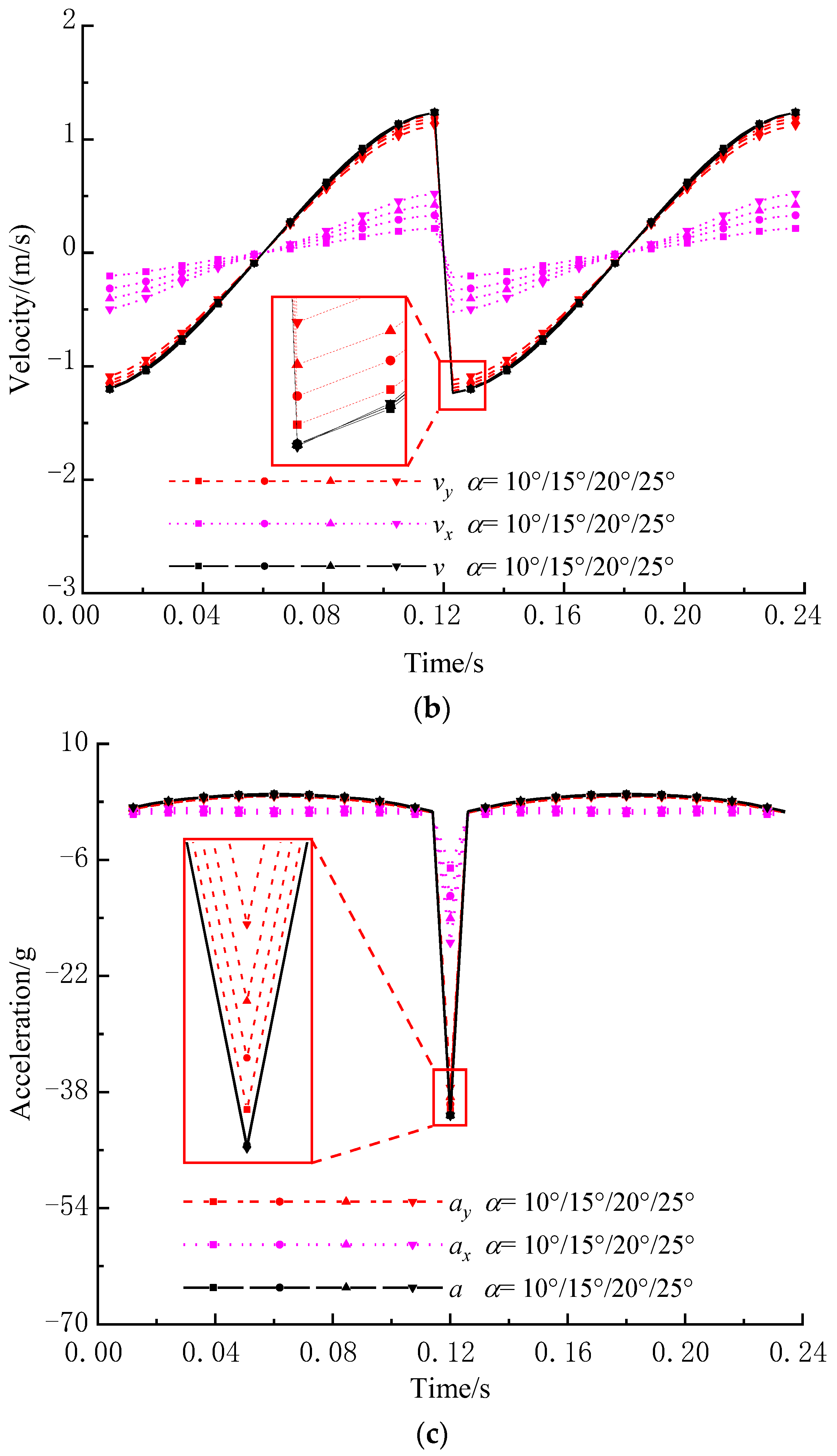
3.3.3. Effect of Incline Angle α

When α, Δl and e are 500 r/min, 0 mm and 6 mm, respectively, displacement, velocity and acceleration of the midpoint change with α, as shown in Figure 10. In addition, s, sx and sy are still W-shaped, and the absolute value of sy is still slightly smaller than that of s and is still larger than that of sx. With the increase in α, the curve of s almost remains unchanged, while the absolute value of sx increases slowly and the absolute value of sy decreases slightly. Additionally, v, vx and vy are still N-shaped, and the absolute value of vy is still slightly smaller than that of v and is still larger than that of vx. With the increase in α, the curve of v almost remains unchanged, while the absolute value of vx increases slowly and the absolute value of vy decreases slightly. Furthermore, a, ax and ay are still umbrella-shaped, the absolute value of ay is still slightly smaller than that of a and is still larger than that of ax. With the increase in α, the curve of a almost remains unchanged, while the absolute value of ax increases slowly and the absolute value of ay decreases slightly.
Overall, with the increase in α, the absolute value of transverse components of displacement, velocity and acceleration increases slowly and the absolute value of longitudinal components of displacement, velocity and acceleration decreases slightly. Moreover, large α will lead to short screening time, which is unfavorable to high screening efficiency; while small α will lead to long screening time, which is unfavorable to large flow rate. So, a reasonable α should be selected for reasonable screening time.

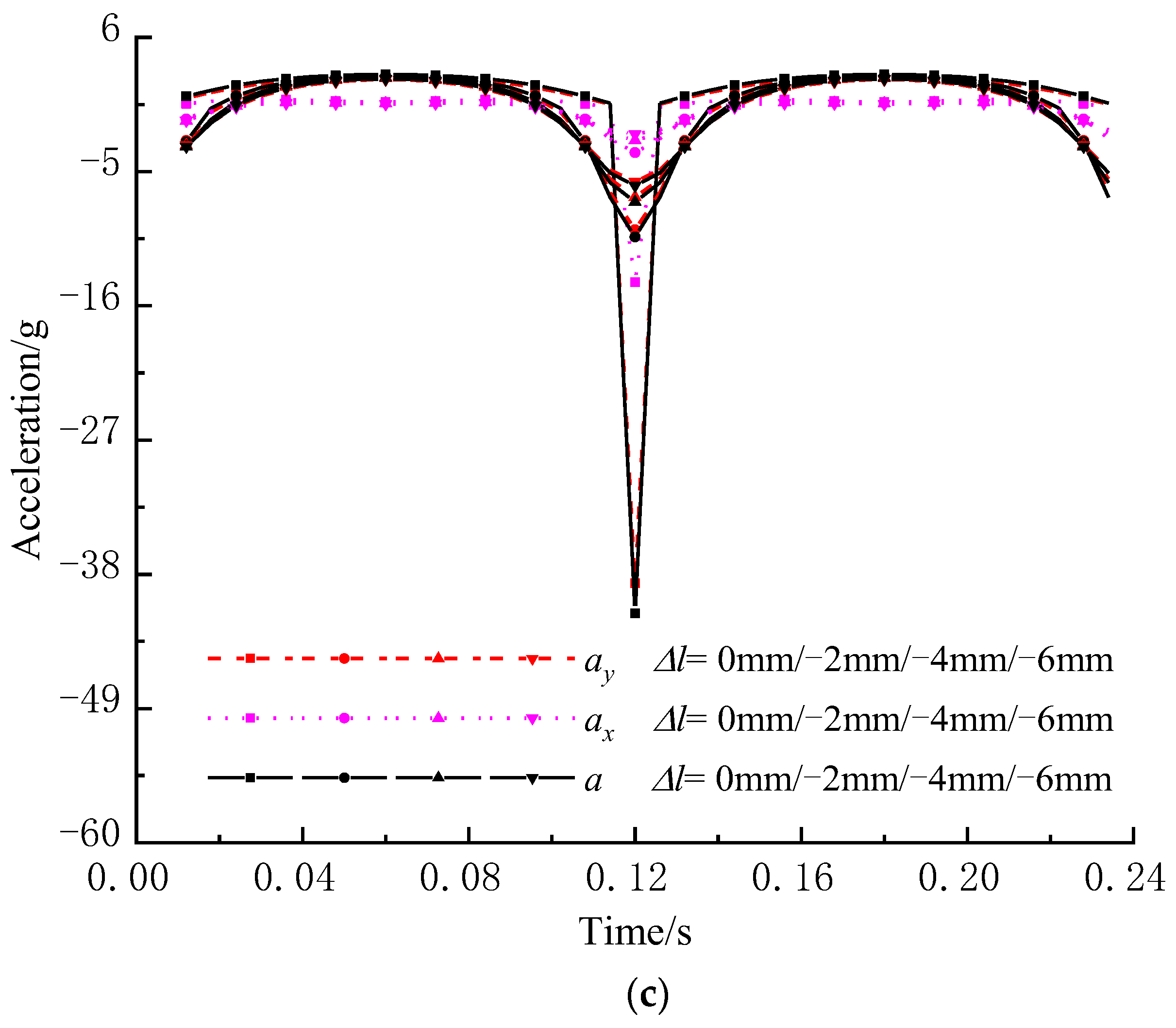
3.3.4. Effect of Tensional Amount Δl

When n, α and e are 500 r/min, 20° and 6 mm, respectively, displacement, velocity and acceleration of the screen midpoint change with Δl, as shown in Figure 11. In addition, s, sx and sy are still W-shaped, and the absolute value of sy is still slightly smaller than that of s and is still larger than that of sx. With the increase in Δl, the period of s, sx and sy remains unchanged, and the absolute value of s, sx and sy increases rapidly. Additionally, v, vx and vy are still N-shaped, and the absolute value of vy is still slightly smaller than that of v and is still larger than that of vx. With the increase in Δl, the period of v, vx and vy remains unchanged, and the absolute value of v, vx and vy increases slowly. Furthermore, a, ax and ay are still umbrella-shaped, the absolute value of ay is still slightly smaller than that of a and is still larger than that of ax. With the increase in Δl, the period of a, ax and ay remains unchanged, and the absolute value of a, ax and ay increases rapidly, especially a and ay.
Overall, with the increase in Δl, the absolute value of displacement, velocity and acceleration increases. Moreover, large Δl will lead to short screening time and small Δl will lead to low vibration intensity, both of which are unfavorable to high screening efficiency and large flow rate of viscous particles. So, a reasonable Δl should be selected for both enough screening time and high vibration intensity.

4. Conclusions

(1)
A novel kinematic model of the flip-flow screen panel, namely the inclined catenary model, is developed. Displacement, velocity and acceleration of each point in the screen panel can be calculated by using the inclined catenary model, and the effects of screening parameters on kinematic characteristics can be obtained.
(2)
After comparing theoretical kinematic characteristics with experimental kinematic characteristics, the inclined catenary model possesses higher prediction accuracy for trajectory, displacement, velocity and acceleration of the flip-flow screen panel than three previous kinematic models.
(3)
With the increase in n, the absolute value of velocity and acceleration increases, while the maximum absolute value of displacement remains unchanged. With the increase in e, the absolute value of displacement, velocity and acceleration increases. With the increase in α, the absolute value of transverse components of displacement, velocity and acceleration increases slowly and the absolute value of longitudinal components of displacement, velocity and acceleration decreases slightly. With the increase in Δl, the absolute value of displacement, velocity and acceleration increases.

Author Contributions

Conceptualization, J.F.; methodology, J.F.; software, Z.H.; validation, Y.Z.; formal analysis, J.F.; investigation, Z.H.; resources, Y.Z.; data curation, Z.H.; writing—original draft preparation, J.F.; writing—review and editing, Z.H.; visualization, M.W.; supervision, J.F.; project administration, J.F.; funding acquisition, Z.H. All authors have read and agreed to the published version of the manuscript.

Funding

This research was funded by Henan Provincial Department of Science and Technology, grant number 202102110113, 232102241022, 222102220075, 212102210623, and Henan Provincial Department of Education, grant number 23A460031, 22B460013, 22A413006, 2022-KJ-47.

Data Availability Statement

All data and models generated or used during the study appear in the submitted article.

Acknowledgments

The authors would like to thank Xinxiang Gaofu Machinery Co., Ltd. for its support.

Conflicts of Interest

The authors declare no conflict of interest.

References

  1. Zhou, Z.; Huang, L.; Jiang, H.; Wen, P.; Zhao, L.L.; Zhao, Y.; Duan, C.; Luo, Z.; Wang, Z.; Liu, C. Kinematics of elastic screen surface and elimination mechanism of plugging during dry deep screening of moist coal. Powder Technol. 2019, 346, 452–461. [Google Scholar] [CrossRef]
  2. Yu, C.; Geng, R.; Wang, X. A Numerical Study of Separation Performance of Vibrating Flip-Flow Screens for Cohesive Particles. Minerals 2021, 11, 631. [Google Scholar] [CrossRef]
  3. Wang, K. Present Situation and Development of Vibrating Screen in China. J. New Energy Dev. 2020, 1, 18–21. [Google Scholar]
  4. Tang, J.; Niu, L.; Xiong, X.; Jie, S. Viscoelasticity of Rubber Springs Affects Vibration Characteristics of a Flip-Flow Screen with the High G Value. IEEE Access 2020, 8, 26950–26965. [Google Scholar] [CrossRef]
  5. Yu, C.; Wang, X.; Gong, S.; Pang, K.; Zhao, G.; Zhou, Q.; Lin, D.; Xu, N. Stability analysis of the screening process of a vibrating flip-flow screen. Miner. Eng. 2021, 163, 106794. [Google Scholar] [CrossRef]
  6. Yu, C.; Wang, X.; Pang, K.; Zhao, G.; Sun, W. Dynamic Characteristics of a Vibrating Flip-Flow Screen and Analysis for Screening 3 mm Iron Ore. Shock. Vib. 2020, 2020, 1031659. [Google Scholar] [CrossRef]
  7. Zhang, J.; Huang, Y.; Chen, Z. The Basic Dynamics Study of Flip-Flow Screen and Particles Based on MATLAB. Appl. Mech. Mater. 2013, 444–445, 1340–1344. [Google Scholar] [CrossRef]
  8. Zou, M.; Liu, C.; Wu, J.; Wang, Z. Influence of tensional amount on dynamic parameters of unilateral driven flip-flow screen surface. J. China Coal Soc. 2018, 43, 567–571. [Google Scholar]
  9. Li, H.; Liu, C.; Shen, L.; Zhao, L.; Li, S. Kinematics characteristics of the flip-flow screen with a crankshaft-link structure and screening analysis for moist coal. Powder Technol. 2021, 394, 326–335. [Google Scholar] [CrossRef]
  10. Li, H.; Liu, C.; Shen, L.; Zhao, L. Vibration Characteristics of an Industrial-Scale Flip-Flow Screen with Crank-Link Structure and Parameters Optimization. Shock. Vib. 2021, 2021, 2612634. [Google Scholar] [CrossRef]
  11. Zhao, Y.; Liu, C.; Fan, M.; Wei, L. Research on acceleration of elastic flip-flow screen surface. Int. J. Miner. Process. 2000, 59, 267–274. [Google Scholar] [CrossRef]
  12. Peng, L.; Li, F.; Dong, H.; Liu, C.; Zhao, Y.; Duan, C. Characteristics analysis of a novel centralized-driving flip-flow screen. Int. J. Min. Sci. Tech. 2014, 24, 195–200. [Google Scholar] [CrossRef]
  13. Peng, L.; Liu, C.; Dong, H.; Li, J.; Xia, Y. Analysis and experiment on the large nonlinear deformation of a flip-flow screen. J. China Coal Soc. 2014, 39, 976–980. [Google Scholar]
  14. Zuber, J. Screening of difficult materials on bivitec screens with flip-flow systems. Aufbereit. Tech. 1995, 36, 303–305. [Google Scholar]
  15. Chen, B.; Yu, C.; Gong, S.; Wang, X. Dynamic characteristics of LIWELL flip-flow screen panel and particle movement. Chem. Eng. Sci. 2021, 245, 116853. [Google Scholar] [CrossRef]
  16. Xiong, X.; Niu, L.; Gu, C.; Wang, Y. Vibration characteristics of an inclined flip-flow screen panel in banana flip-flow screens. J. Sound Vib. 2017, 411, 108–128. [Google Scholar] [CrossRef]
  17. Wu, B.; Zhang, X.; Niu, L.; Xiong, X.; Dong, Z.; Tang, J. Research on Sieving Performance of Flip-flow Screen Using Two-way Particles-screen Panels Coupling Strategy. IEEE Access 2019, 7, 124461–124473. [Google Scholar] [CrossRef]
Figure 1. Schematic diagram of the inclined catenary model.
Mathematics 11 02028 g001
Figure 2. Picture of screen panel. (a) A single screen panel; (b) Screen panel during translational motion experiment.
Mathematics 11 02028 g002
Figure 3. Finite element model of screen panel. (a) Meshes of screen panel; (b) Screen panel during translational motion simulation.
Mathematics 11 02028 g003
Figure 4. Motion trajectory of screen panel under different slack amounts.
Mathematics 11 02028 g004
Figure 5. Midpoint displacement achieved using four theoretical models. (a) Total displacement s; (b) Transverse displacement sx; (c) Longitudinal displacement sy.
Mathematics 11 02028 g005aMathematics 11 02028 g005b
Figure 6. Midpoint velocity achieved using four theoretical models. (a) Total velocity v; (b) Transverse velocity vx; (c) Longitudinal velocity vy.
Mathematics 11 02028 g006aMathematics 11 02028 g006b
Figure 7. Midpoint acceleration achieved using four theoretical models. (a) Total acceleration a; (b) Transverse acceleration ax; (c) Longitudinal acceleration ay.
Mathematics 11 02028 g007aMathematics 11 02028 g007b
Figure 8. Kinematic characteristics of the midpoint under different rotation speed n. (a) Displacement; (b) Velocity; (c) Acceleration.
Mathematics 11 02028 g008aMathematics 11 02028 g008b
Figure 9. Kinematic characteristics of the midpoint under different eccentricity e. (a) Displacement; (b) Velocity; (c) Acceleration.
Mathematics 11 02028 g009
Figure 10. Kinematic characteristics of the midpoint under different incline angle α. (a) Displacement; (b) Velocity; (c) Acceleration.
Mathematics 11 02028 g010aMathematics 11 02028 g010b
Figure 11. Kinematic characteristics of the midpoint under different tensional amount Δl. (a) Displacement; (b) Velocity; (c) Acceleration.
Mathematics 11 02028 g011aMathematics 11 02028 g011b
Table 1. Maximum trajectory error under different slack amounts.
Slack Amount0 mm4 mm8 mm12 mm
Error
Inclined catenary model0 mm1.1 mm1.4 mm1.5 mm
Elastic compressed bar model [11]0 mm2.8 mm3.1 mm4.5 mm
Table 2. Maximum error of midpoint displacement achieved using four theoretical models.
ModelSimplified Geometric Model [7]Elastic Compressed Bar Model [11]Bending Beam Deflection Model [14]Inclined Catenary Model
Error
s (mm)2.8605.2475.3341.943
sx (mm)4.3325.3060.9890.618
sy (mm)1.3433.5126.1372.264
Table 3. Maximum error of midpoint velocity achieved with four theoretical models.
ModelSimplified Geometric Model [7]Elastic Compressed Bar Model [11]Bending Beam Deflection Model [14]Inclined Catenary Model
Error
v (m/s)0.0320.0520.0590.030
vx (m/s)0.0420.0480.0090.008
vy (m/s)0.0160.0340.0670.028
Table 4. Maximum error of midpoint acceleration achieved using four theoretical models.
ModelSimplified Geometric Model [7]Elastic Compressed Bar Model [11]Bending Beam Deflection Model [14]Inclined Catenary Model
Error
a (g)4.72
ax (g)2.19
ay (g)4.58
Disclaimer/Publisher’s Note: The statements, opinions and data contained in all publications are solely those of the individual author(s) and contributor(s) and not of MDPI and/or the editor(s). MDPI and/or the editor(s) disclaim responsibility for any injury to people or property resulting from any ideas, methods, instructions or products referred to in the content.

