Article

A Posteriori Error Estimators for the Quasi-Newtonian Stokes Problem with a General Boundary Condition

1
Laboratory of Mathematics and Applications, ENS, Hassan II University Casablanca, Casablanca 20000, Morocco
2
Mechanical Engineering Laboratory, Faculty of Science and Technology, University Sidi Mohammed Ben Abdellah, B.P. 30000 Route Imouzzer, Fez 30000, Morocco
3
Département de Mathématiques, Centre Regional des Métiers d’Education et de Formation de Fès Meknès (CRMEF Fès-Meknès), Rue de Koweit 49, Ville Nouvelle, Fez 30050, Morocco
4
Department of Mechanical Engineering, Faculty of Mechanical Engineering, Transylvania University of Brasov, B-dul Eroilor 29, 500036 Brasov, Romania
5
Romanian Academy of Technical Sciences, B-dul Dacia 26, 030167 Bucharest, Romania
*
Author to whom correspondence should be addressed.
Mathematics 2023, 11(8), 1943; https://doi.org/10.3390/math11081943
Submission received: 5 March 2023 / Revised: 15 April 2023 / Accepted: 18 April 2023 / Published: 20 April 2023

Abstract

:
In this paper, we approach two nonlinear differential equations applied in fluid mechanics by finite element methods (FEM). Our objective is to approach the solution to these problems; the first one is the “p-Laplacian” problem and the second one is the “Quasi-Newtonian Stokes” problem with a general boundary condition. To study and analyze our solutions, we introduce the a posteriori error indicator; this technique allows us to control the error, and each is shown the equivalent between the true and the a posterior errors estimators. The performance of the finite element method by this type of general boundary condition is presented via different numerical simulations.
MSC:
65N30; 65N15; 65G99; 76D07; 76D99

1. Introduction

One of the important objectives of numerical studies of differential problems is: to have a “realistic simulation”; for this, many researchers have concentrated on controlling the error by using the adaptive finite element methods (FEM) meshes. The adaptive meshes provide effective means of optimizing calculation with reasonable results; “the meshes are automatically modified by enhancing the scope of their applications”. The error estimation technique provides an assessment of the accuracy of the solutions obtained by the finite element solvers, see [1,2] for more precise details. These techniques can efficiently offer certain flow features (stagnation, reattachment points, and recirculation eddies, with small velocity magnitudes). Generally, this technique is based on a posteriori local error estimation, see [3].
Nonlinear differential equations are used to model complex problems in the sciences and engineering. Many studies have been developed to simplify these complex models. Among these models, we mention the “p-Laplacian” equation and the “Quasi-Newtonian Stokes” system. These nonlinear equations have had more attention in recent years, and one of the important domains using these equations is the glaciology domain. These equations model the dynamics of ice sheets or glaciers, see [4], and the evolution of glacier geometry, see [5,6]. Another application in the biological domain is the common use for blood flows, see [7] for details.
One of the important domains that uses these equations is fluid mechanics. For example, to model “viscoelastic” fluids we use the “Quasi-Newtonian Stokes” method, see [8] for more details. This quasi-Newtonian law was first proposed by Carreau et al. in [9]; a popular extension to the Carreau law is studied by Yasuda et al. in [10] and a closely related model, the Cross law, is investigated by Cross in [11]. The well-posedness of these problems is established in these papers [12,13]. Much mathematical modeling for complex fluids and numerical algorithms are applied to solve linear/nonlinear equations, see [14]. The fully non-linear elliptic problems in divergence form by using a mixed finite volume scheme are studied in [15]; the discontinuous Galerkin approximation was considered in [5] and the hybrid high-order scheme was studied in [16]. The paper where the authors studied the comportment of solutions of some non–linear diffusion problems and in the boundary–layer flow of a pseudo-plastic fluid is given [17]. The a posteriori error estimator for elliptic partial differential equations by using finite elements is presented in [18] and proves some (elliptic) a posteriori error estimators. The p-Laplacian problem is studied by using a FEM method in many papers, see [19,20,21,22] for details. In [23,24], the authors analyzed a posteriori error estimators for quasi-Newtonian problems with a homogeneous Dirichlet boundary condition. There are at least as many relevant references over the past 30 years on the quasi-Newtonian Stokes problem concerning the posterior estimate and its use in adaptivity; there were important developments in the Chinese [25,26,27], German [28,29,30], and French [31,32] schools for flow fluid in complex porous media using new boundary conditions [33] and combined mixed finite element [34].
This paper is organized as follows: in Section 2 and in order to study the p-Laplacian problem with the new boundary condition, we introduce some useful notations, state our main assumptions regarding the modeling equations, and following a finite element discretization, we calculate error estimators with respect to the true error. Section 3 contains the description of our second problem (quasi-Newtonian system) which is discretized by a mixed finite element scheme. The a posteriori error estimator is developed in terms of the Residus of variational formulas with respect to the real error. Section 4 presents two numerical examples using a velocity angle error indicator.
The authors propose the study of two nonlinear differential equations that have applications in fluid mechanics, using FEM. These problems are studied in two steps, within the “p-Laplacian” problem, and then solving the “Quasi-Newtonian Stokes” problem imposing a general boundary condition. To study and analyze our solutions, an a posteriori error indicator will be introduced. In this way, there is the possibility to control the error at each step and compare the calculated error with the a posteriori error. The obtained results are supported by several numerical simulations that we considered significant for the presentation of the research.

2. Approximation of p-Laplacian Equation by Finite Element Method

The section aims to study the p-Laplacian equation with a nonhomogeneous Robin boundary condition; we use FEM to approximate this model. To analyze the error, we use the a postriori estimates for the Dirichlet boundary condition, see [17,24,35]. First of all, we recall some useful properties of generalized nonlinear diffusion problems and we investigate the existence/uniqueness of the solution. Let Ω be an open-bounded (connected) subset of d ( d = 2 , 3 ) whose boundary Γ = Ω, and let β * with conjugate β = β β + 1 .

2.1. Results of the p-Laplacian Operator

We consider the generalized nonlinear diffusion problem, defined by
φ ( x , u ( x ) ) = f ( x )   in   Ω ,
where the flux φ : Ω × 2 2 is assumed to satisfy the following assumptions:
There exist two positive constants C 1 , C 2 , and two functions b 1 L 1 ( Ω ) and b 2 L β ( Ω ) such that
{ ( φ ( x , y ) φ ( x , z ) , y z ) > 0 , ( H 1 ) ( φ ( x , y ) , y )   C 1 | y | β b 1 ( x ) , ( H 2 ) φ ( x , y )   C 2 | y | β 1 b 2 ( x ) , ( H 3 )
for all x , y , z Ω with y z .
Under these assumptions the problem (1) has a unique solution u W 1 , β ( Ω ) , and the functional u div ( φ ( , u ( ) ) ) is a Leray–Lions operator which satisfies
u ( L β ( Ω ) ) 2 φ ( , u ( ) ) ( L β ( Ω ) ) 2 .
The p-Laplacian equation is defined by
a ( u ) = f   in   Ω ,
where the vector field a ( ζ ) = | ζ | β 2 ζ and β * .
The p-Laplacian equation is a nonlinear diffusion problem. Now, we recall some key lemmas useful to prove the monotonicity and continuity properties of such operators, see [12,20].
Let z = ( z 1 , z 2 ) 2 and let us define the following operator
A ( ) : u V A ( u ) = ( | u | β 2 u ) V ,
where space V depends on the boundary condition and V its dual. In order to prove the ellipticity of the problem, we need the following lemma.
Lemma 1. 
For all y , z 2 , we have
{ ( | z | β 2 z | y | β 2 y , z y ) α | z y | β 1   if   β 2 , ( | z | + | y | ) 2 β ( | z | β 2 z | y | β 2 y , z y ) α | z y | 2   if   1 < β 2 ,
where α > 0 is independent of y and z .
Proof. 
See [12]. □
Proposition 2 (Ellipticity). 
For all u , v V , we have the following ellipticity properties
{ ( A ( u ) A ( v ) , u v ) α u v β   if   β 2 , ( u + v ) 2 β ( A ( u ) A ( v ) , u v ) α u v 2   if   1 < β 2 ,
Proof. 
A direct consequence Lemma 2.1 from [12] for a detailed proof. □
To proof the continuity property, it needs the following lemma,
Lemma 3. 
For all y , z 2 , we have
{ | z | β 2 z | y | β 2 y α | z y | ( | z | + | y | ) β 2 if β 2 , | z | β 2 z | y | β 2 y α | z y | β 1 if 1 < β 2 ,
where α > 0 is independent of y and z .
Proof. 
See [12]. □
Proposition 4 (Continuity). 
For all u , v V , we have the following continuity properties
{ A ( u ) A ( v ) * α u v ( u + v ) β 2   if   β 2 , A ( u ) A ( v ) * α u v β 1   if   1 < β 2 ,
here α > 0 , independent to u and v .
Proof. 
A (direct) consequence of the lemma 2.1, see also [12] for a detailed proof. □

2.2. Mathematical Problem

The practical applications of the p-Laplacian equations [4,5,36] have previously been mentioned; which, proved useful in a wide range of applications. For example, glacier dynamics are an important topic in engineering and hydrology. Thus, the ice flow is assumed to be an incompressible fluid with nonlinear viscosity. Next, let us consider the problem of the model
a ( u ) = f   in   Ω   ,
with   a ( ζ ) = | ζ | β 2 ζ and f L β ( Ω ) . Note that if β = 2 , it coincides with the linear Laplacian operator, i.e., A = Δ .
This equation can then be carried with the following new boundary conditions
{ α ( u ) u + ( | u | β 2 u ) n = g on   Γ N D , u = 0 on   Γ D ,
where α L ( Γ ) ( α > 0 ) and g W 1 1 β , β (Ω).
Theorem 1. 
The problems (5) and (6) have a unique solution u W 1 , β ( Ω ) .
Proof. 
The proof is a consequence of ellipticity–continuity assumptions on the operator A. □
The systems (5) and (6) are equivalent to a minimization problem (see [12,13]) defined by: find u V such that
J ( v ) J ( u ) , v V ,
where
J ( u ) = 1   β Ω | u | β + 1   2 Γ N D α | u | 2 Ω f v Γ N D g v ,
for all v V .
The function J is continuous, strictly convex, and differentiable operator with lim v J ( v ) = + ; it results, see [37], that J is Gateaux differentiable and (7) admits a unique solution characterized by its variational formulation: find u V such that
Ω ( | u | β 2 u ) v + Γ N D α u v = Ω f v + Γ N D g v ,
for all v V .
Now, in order to analyze the finite element approximation of the problem (9), we consider a regular mesh T h , h > 0 , of the domain Ω . For any element T T h , we define: ω T the set of elements share at least one edge with T ; ω ˜ T the set of all elements sharing at least one vertex with T ; ε ( T ) the set of edges of T ; h T the diameter of the simplex T ; and h = max T T h h T . Respectively, for edge elements E T with T T h : ω E is the set of elements sharing at least one edge with E ; ω ˜ E the set of all elements sharing at least one vertex with E ; and h E the diameter of a face E of T . Let ε h = T T h ε ( T ) designate the set of all edges; hence, one can divide it into interior and exterior edges such that ε h = ε h , Γ   ε h , Ω with
ε h , Ω = { E ε h : E Ω } ,   ε h , Γ = { E ε h : E Γ } .
Let V h V = W 1 , β ( Ω ) , the finite dimensional spaces associated to regular partition of Ω , and a discrete weak formulation is defined using finite dimensional spaces as: find the vector u h V h such that
Ω ( | u h | β 2 u h ) v h + Γ α u h v h = Ω f v h + Γ g v h ,
for all v h V h .

2.3. A Posteriori Error Estimator

We illustrate the proposed technique with results of the a posteriori error estimation for the p-Laplacian problem. Denoting u the solution of (5) and (6) and u h the approched solution of (10). Our aim is to estimate the velocity error e = u u h V by using some important results.
Lemma 6. 
There is a constant C > 0 for all the elements K T h and v W 1 , β ( Ω ) , such that
h T v 0 , β , K β C ( v 0 , β , K β + v 1 , β , K β ) ,
Proof. 
See [24]. □
Lemma 7 (Clement interpolation estimate). 
There is a constant C > 0 , for any K T h and for all E K , let v V and π h the operator of the interpolation of discontinuous functions defined by Clement satisfying
v π h v 0 , β , K C h K 1 m K S K v 0 , β , ω ˜ K
for all v H 1 ( S K ) , and m = 0 or 1 .
Where S K = { K , K K } . In particular, for v h , is the quasi-interpolant of v defined by averaging as in
v v h 0 , β , K C h k 1 m | v | 1 , β , ω ˜ K
with m = 0 or 1 .
Proof. 
See [12,24]. □
The residual error estimator R : V is given by
R , v = Ω | u h | β 2 u h v + Γ α u h v Ω f v Γ g v ,
By applying the Green formula, we obtain
R , v = K T h { K | u h | β 2 u h v + Γ K α u h v K f v Γ K g v } = K T h { K ( ( | u h | β 2 u h ) f ) v + K | u h | β 2 u h n v + Γ K α u h v + | u h | β 2 u h n v g v } = K T h { K ( ( | u h | β 2 u h ) f ) v + l K l | u h | β 2 u h n v + l Γ K l ( α u h + | u h | β 2 u h n g ) v } .
Because R , v h = 0 for all v h V h , we use the interpolation operator π h to obtain
R , v = K T h { K ( ( | u h | β 2 u h ) f ) ( v π h v ) + l K l | u h | β 2 u h n ( v π h v ) + l Γ K l ( α u h + | u h | β 2 u h n g ) ( v π h v ) }
and
R , v K T h { K | ( | u h | β 2 u h ) f | 0 , β , K | v π h v | 0 , β , K + l K l | | u h | β 2 u h n | 0 , β , l | v π h v | 0 , β , l + l Γ K l | α u h + | u h | β 2 u h n g | 0 , β , l | v π h v | 0 , β , l } .
So, by (12), we get
R , v C K T h h K | ( | u h | β 2 u h ) f | 0 , β , K v 1 , β , K + K T h { C l K | [ | u h | β 2 u h n ] l | 0 , β , l . | v π h v | 0 , β , l + C l Γ K | α u h + | u h | β 2 u h n g | 0 , β , l . | v π h v | 0 , β , l } .
For the first term of the second member, we have
I 1 = K T h h K | ( | u h | β 2 u h ) f | 0 , β , K . v 1 , β , K C ( K T h h K β | ( | u h | β 2 u h ) f | 0 , β , K β ) 1 β v 1 , β , K .
Now, we increase the second term as follows
I 2 = l K | [ | u h | β 2 u h n ] l | 0 , β , l | v π h v | 0 , β , l = l K h l 1 β | [ | u h | β 2 u h n ] l | 0 , β , l . h l 1 β | v π h v | 0 , β , l ( l K h l | [ | u h | β 2 u h n ] l | 0 , β , l β ) 1 β × ( l K h l β β | v π h v | 0 , β , l β ) 1 β .
Using (11), we have
l K h l β β | v π h v | 0 , β , l β C K T h h K β β | v π h v | 0 , β , K β C K T h h K ( 1 + β β ) ( | v π h v | 0 , β , K β + h K β | v π h v | 1 , β , K β ) C K T h h K ( 1 + β β ) ( h K β | v | 1 , β , K β + h K β | v | 1 , β , K β ) .
As 1 + β β = β , it implies that
I 2 l K | [ | u h | β 2 u h n ] l | 0 , β , l . | v π h v | 0 , β , l C ( l K h l | [ | u h | β 2 u h n ] l | 0 , β , l β ) 1 β × | v | 1 , β , Ω .
Now, it is simple to increase the third term as follows
I 3 = l Γ K h l 1 β | α u h v + | u h | β 2 u h n v g | 0 , β , l h l 1 β | v π h v | 0 , β , l ( l Γ K h l | α u h + | u h | β 2 u h n g | 0 , β , l β ) 1 β × ( l K h l β β | v π h v | 0 , β , l β ) 1 β ( l Γ K h l | α u h + | u h | β 2 u h n g | 0 , β , l β ) 1 β × | v | 1 , β , Ω .
Hence, by combining (19), (22), and (23) we get
R , v C { ( K T h h K | ( | u h | β 2 u h ) + f | 0 , β , K β ) 1 β + ( l K h l | [ | u h | β 2 u h n ] l | 0 , β , l β ) 1 β + C ( l Γ K h l | α u h + | u h | β 2 u h n g | 0 , β , l   β ) 1 β } v .
As a 1 β + b 1 β 2 1 β ( a + b ) 1 β for a and b 0 , we have the following estimate
R * = A ( u ) A ( u h ) * ( C K T h η K β ) 1 β ,
with the contribution element of η K , the residual error estimator is given by
η K β = h K β R K 0 , β , K β + l K h l R l 0 , β , l β ,
his components are given by
R K = { ( | u h | β 2 u h ) + f } K ,
and
R l = { 1 2 [ | u h | β 2 u h n ] l if l ε h , Ω , α ( u h ) u h + | u h | β 2 u h n g if l ε h , Γ .
where [ ] l is the jump of the derivative of u h over the interior edge l = T S , defined by
[ | u h | β 2 u h n ] l = ( ( | u h | β 2 u h n ) | T ( | u h | β 2 u h n ) | S ) n E , T .  
It remains to connect R * and u u h , which uses a coercivity property of the operator A : V W 1 , β for β ] 1 , 2 [ , where we have
A ( u ) A ( v ) , u v C u v 2 ( u + v ) 2 β   ,
for all u , v W 1 , β ( Ω ) , where C is a constant that does not depend on either u or v . By taking v = 0 , in (29), with u as the solution of problem (5), we get (since A ( 0 ) = 0 )
A ( u ) , u α u β .
As A ( u ) = f , then α u β f , u f W 1 , β ( Ω ) . u , which implies (since the injection of L β ( Ω ) in W 1 , β ( Ω ) is continuous)
u ( 1 C f W 1 , β ( Ω ) ) 1   β 1 C ( f L β ( Ω ) ) 1   β 1 .
Similarly, for u h , we have
( u + u h ) 2 β C ( f L β ( Ω ) ) 2 β   β 1 .
Finally, from (19), (22), and (23), we obtain the following result.
Theorem 8. 
For any mixed finite element approximation defined on regular grids T h , the residual estimator satisfies
e C ( K T h η K β ) 1 β ,
where C is independent of β , Ω , a , and f .
Proof of Theorem 8. 
A direct consequence of these inequalities (15) to (29). □
Remark 9. 
Some remarks are in order: for β 2 , we obtain
e C ( K T h η K β ) 1 β
where C is independent of u and f , in this case and instead of (29), we have
A ( u ) A ( v ) , u v α u v β ,    
u , v W 1 , β ( Ω ) .
This result also holds for stable (and unstable) mixed approximations defined on a regular triangulation.

3. Approximation of Quasi-Newtonian Stokes Problem by Finite Element Method

In reality, the comportment of fluids is more complex; this type of fluid is modeled by nonlinear operators or tensors. Let us start this part with some definitions of fluid that we will treat. The type of fluid that is more important is modeled by a nonlinear operator; the problem is the quasi-Newtonian Stokes flow. For many details on the different models and algorithms solving these problems, see [14].

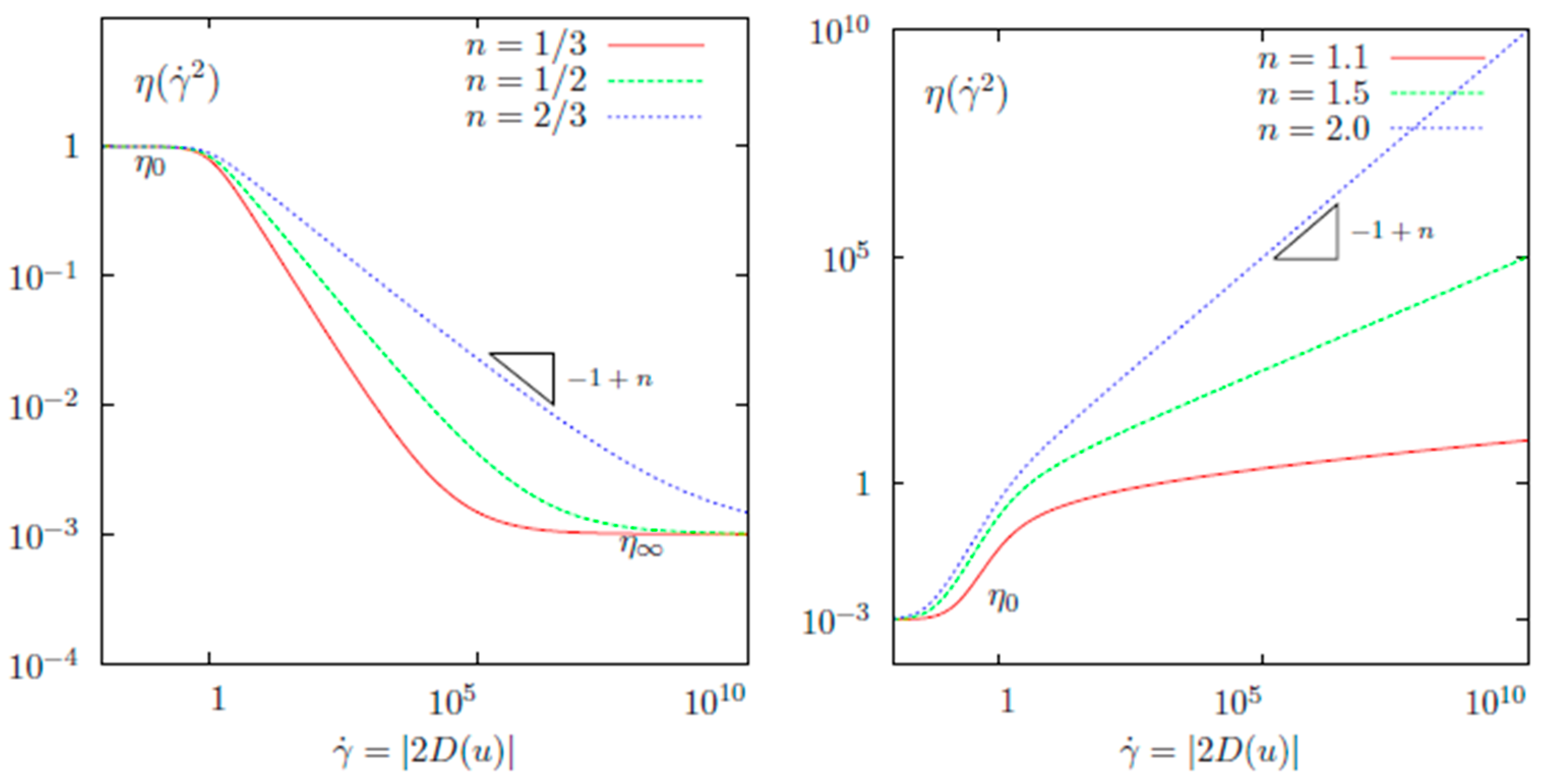
3.1. Definition of Quasi-Newtonian Stokes Problem

We denote by u the velocity vector, p the pressure, σ the stress tensor, D ( u ) the symmetric gradient of the velocity vector, and f the external forces.
Definition 1 (Quasi-Newtonian fluid). 
The fluid is said to be quasi-Newtonian when there exists a positive function μ : + + called the “viscosity” function, such that the stress deviator σ is expressed as
σ = p I + 2 μ ( | 2 D ( u ) | 2 ) D ( u ) .  
There are two classical laws of quasi-Newtonian Stokes problems, the first one is the “Carreau law viscosity” and the second one is the “power law viscosity”.
Definition 2 (Carreau law viscosity). 
The Carreau law expresses the viscosity as
μ ( s ) = μ + ( μ 0 μ ) ( 1 + λ s ) 1 + n 2 ,   s + ,
where μ 0 , μ , λ , n + * are given real constants satisfying μ 0 μ when n 1 and μ 0 μ when n 1 .
The Figure 1 presents Carreau law viscosity for n < 1 and for n > 1 . We can see that under simplification conditions, the Carreau law viscosity can be rewritten as power law viscosity defined by
μ ( ζ ) = K ζ 1 + n 2 ,     ζ ,
where K and n + * .
Note that, when n = 1 , both the power law and Carreau law are reduced to a Newtonian fluid model with constant viscosity. When n < 1 , the viscosity is decreasing with the shear rate and the fluid is said to be “shear thinning” or “pseudoplastic”. The tensor norm and the shear rate are defined as follows (see [14], Definition 1.9 for more precise details).
Definition 3 (Tensor norm). 
The following tensor norm is defined as
| τ | 2 = τ : τ 2 = 1 2 i = 1 3 j = 1 3 τ i , j 2 , τ 3 × 3 .
Definition 4 (Shear rate). 
The shear rate, denoted by γ ˙ , is defined by
γ ˙ = | 2 D ( u ) | .  
Note that, the stress tensor σ in Newtonian fluid flow is “generally” defined by σ = p I + 2 μ D ( u ) , where μ is the fluid viscosity (a bound function).

3.2. Mathematical Problem

To simplify this study, the stationary case where the flow is incompressible remains; hence, we neglect the inertia term which will allow us to focus on the nonlinearity of results (from the viscosity law). The governing system can be written as
{ div ( 2 μ ( | 2 D ( u ) ) | 2 ) D ( u ) ) + p = f   in   Ω , div u = 0   in   Ω ,
where f X , we define the general boundary condition C a , μ by
C a , μ : a ( u ) u + ( 2 μ ( | 2 D ( u ) | 2 ) D ( u ) p I ) n = g   on   Γ ,
where g Γ and a ( u ) are a bounded function defined in the boundary.
The existence and unique solution ( u , p ) of the problem (35) and (36) is defined in the product space X × M with X = ( H 1 ( Ω ) ) 2 and M = L 2 ( Ω ) . The operator A = 2 μ ( | 2 D ( u ) | 2 ) D ( u ) : X X , appearing in (35), satisfies the following two propositions.
Proposition 10. 
For all u , v X , we have
A ( u ) A ( v ) , u v C ( u , v ) u v 2 ,
where
C ( u , v ) = { α 1 + α 2 ( u + v ) 2 β } 1 ,
with α 1 ,   α 2 > 0 .
Proposition 11. 
For all u , v in X and all β > 1 , there exists a positive constant C > 0 such that
A ( u ) A ( v ) X C ( u , v ) u v X .
Proof of Proposition 10 and 11. 
See [38]. □
It should be noted that conditions (37) and (38) are satisfied for a fluid with a power law viscosity, see, e.g., [12,39]. For the existence and uniqueness of the solution, we refer to the works [17,40] by Baranger and Najib. The variational formulation to the problem (35) and (36) is equivalent to: find ( u , p ) X × M such that
{ A ( u ) , v + B v , p = f , v , B u , q = g , q ,
for all ( v , q ) X × M , where
A ( u ) , v = Ω ( 2 η ( | 2 D ( u ) | 2 ) : D ( u ) ) D ( v ) d x + Γ α u v d γ ( x ) ,
and
B v , q = Ω q   div ( v ) .
Theorem 12. 
The problem (39) has a unique solution ( u , p ) X × M if and only if (40) has a unique solution and B is surjective satisfying the inf-sup condition.
Proof. 
See [17,41]. □
The functional spaces X and M are Hilbert spaces, then ( u , p ) (resp. ( U , P ) ) is a solution of problem (39) associated to the couple ( f , g ) (resp. ( F , G ) ) such that
u U + p P C ( f F * + | g G | * ) ,
where C is a positive constant, see [42] for more details.
We have to describe the discrete approximation problem corresponding to (39)–(41) by using notations of Section 2; to this aim, we define the finite element spaces ( X h , M h ) ( X , M ) , where the discrete approximation of the quasi-Newtonian flow problem (with C a , μ boundary condition) can be equivalently written as: find ( u h , p h ) X h , M h such that
{ Ω ( 2 μ | 2 D ( u h ) | 2 ) D ( u h ) : D ( v h ) + p h v h d + Γ a u h v h d γ = Ω f v d x + Γ g v h d γ , x Ω q h   div u h   d x = 0 ,  
for all ( v h , q h ) X h × M h .
Under properties (3.2) and (3.2), and assuming the inf-sup condition is satisfied in the discrete approximation problem (42), we obtain one solution, ( u h , p h ) X h × M h .

3.3. A Posteriori Error Estimator

A posteriori error indicator and residual error for quasi-Newtonian problems with Dirichlet and Newman boundary conditions are developed in these papers [17,24,35]. Based on these results, one can adapt their estimates to the case of our problem (42); by using the notation μ h = 2 μ | 2 D ( u h ) | 2 , we get
R , v = K T h K d i v ( 2 μ | 2 D ( u h ) | 2 ) D ( u h ) D ( v ) K T h K p h div v K T h K f v + K T h K Γ α u h v + K T h K Γ g v .
From Green’s formula, and for any element K , we obtain
R , v = K T h ( K ( A ( u h ) + p h f ) v + K ( μ h D ( u h ) n p h n ) v + K Γ α u h v + K Γ g v ) = K T h ( K ( A ( u h ) + p h f ) v + K ( μ h D ( u h ) n p h n ) v + K Γ α u h v + ( μ h D ( u h ) n p h n ) v g v ) = K T h ( K ( A ( u h ) + p h f ) v + l ε h l ( μ h D ( u h ) n p h n ) v + l ε Γ l α u h v + ( μ h D ( u h ) n p h n ) v g v )
where ε Γ is the set of all edges of all elements T h divided into interior and exterior edges ε h = ε h , Γ ε h , Ω with ε h , Ω = { E ε h : E Ω } and ε h , Γ = { E ε h : E Γ } . As R , v h = 0 for all v h X h , and for v h = π h v , we get
R , v = R , v π h v = K T h K ( A ( u h ) + p h f ) ( v π h v ) + l ε h l ( μ h D ( u h ) n p h n ) ( v π h v ) + l ε Γ l ( α u h + ( μ h D ( u h ) n p h n ) g ) ( v π h v ) .
Hence
R , v K T h | A ( u h ) + p h f | 0 , K | v π h v | 0 , K + l ε h | μ h D ( u h ) n p h n | 0 , l | v π h v | 0 , l + l ε Γ | α u h + ( μ h D ( u h ) n p h n ) g | 0 , l | v π h v | 0 , l .
In order to deal with the three terms of the right-hand side, we write
K T h | A ( u h ) + p h f | 0 , K | v π h v | 0 , K ( K T h h K 2 | A ( u h ) + p h f | 0 , K 2 ) 1 2 ( K T h h K 2 | v π h v | 0 , K 2 ) 1 2
we use Lemma 3 (when m = 0 ) to obtain
K T h | A ( u h ) + p h f | 0 , K | v π h v | 0 , K ( K T h h K 2 | A ( u h ) + p h f | 0 , K 2 ) 1 2 v .
Defining the vector s
s = | μ h D ( u h ) n p h n | 0 , l = | [ σ ( u h , p h ) n ] l | 0 , l = | [ σ h n ] l | 0 , l ,
the second term of the right-hand side is rewritten as
l ε h s | v π h v | 0 , l ( l ε h h l | s | 2 ) 1 2 ( l ε h h l 1 | v π h v | 0 , l 2 ) 1 2 .
Observe that
( K T h l ε h h l 1 | v π h v | 0 , l 2 ) 1 2 ( K T h C h K 1 | v π h v | 0 , l 2 ) 1 2 = C ( K T h h K 1 | v π h v | 0 , l 2 ) 1 2 ,
then, one can use lemma 3 (with β = 2 ) to get
( K T h l ε h h l 1 | v π h v | 0 , l 2 ) 1 2 C ( K T h h K 2 | v π h v | 0 , K 2 + K T h h K 2 | v π h v | 1 , K 2 ) 1 2 C ( K T h | v | 1 , K 2 ) 1 2 = C v .
Thus, the second term of (45) is increased by
C ( l ε h | [ σ ( u h , p h ) n ] l | 0 , l 2 ) 1 2 v .
To treat the last term of (45), we write §
l ε h | α u h + s g | 0 , l | v π h v | 0 , l ( l ε h h l | α u h + s g | 2 ) 1 2 ( l ε h h l 1 | v π h v | 0 , l 2 ) 1 2 ,
by using lemma 3 and (50), the last term of (45) is increased by
C ( l ε h | [ ( α u h + σ ( u h , p h ) g ) n ] l | 0 , l 2 ) 1 2 v .
Finally, we conclude
R , v C ( K T h h K 2 | A ( u h ) + p h f | 0 , K 2 ) 1 2 v + C ( l ε h | [ σ ( u h , p h ) n ] l | 0 , l 2 ) 1 2 v + C ( l ε h | [ ( α u h + σ ( u h , p h ) g ) n ] l | 0 , l 2 ) 1 2 v ,
where
R * C ( K T h h K 2 | A ( u h ) + p h f | 0 , K 2 ) 1 2 + C ( l ε h | [ σ ( u h , p h ) n ] l | 0 , l 2 ) 1 2 + C ( l ε h | [ ( α u h + σ ( u h , p h ) g ) n ] l | 0 , l 2 ) 1 2 .
Finally, from (47), (50), and (51) we obtain the following result:
Theorem 13. 
There exists a constant C (independent of h ) such that
u u h + p p h C ( K T h η ( K ) 2 ) 1 2
where
η ( K ) = h K 2 | A ( u h ) + p h f | 0 , K 2 + l ε h K | [ σ ( u h , p h ) n ] l | 0 , l 2 + l ε Γ K | [ ( α u h + σ ( u h , p h ) g ) n ] l | 0 , l 2 + | div u h | 0 , K 2 .
Proof of Theorem 13. 
A direct consequence of these inequalities (43) to (53). □
Remark. 
For more complex models where the dependence of the viscosity with respect to the second invariant is more strongly nonlinear (for example Carreau law with μ = 0 or power law), we should use both methods of Section 2 and Section 3 and a nonlinear version of Theorem 3.3, in [43].
These systems are written as a big matrix (his component is nonlinear). In these simulations, we used the GMRES (GMRES is a generalized minimal residual algorithm applied to solve nonsymmetric linear systems, see [31,41,42] for more details.) algorithm to accelerate simulation.

4. Numerical Simulations

To conclude this paper, and in order to see the performance of the finite element method for the nonlinear equations, two different numerical simulations are represented: the first one uses the finite element software package “IFISS toolbox “ (IFISS software library is an algorithm executed under MATLAB for the interactive numerical study of differential equations for incompressible flow problems) to solve the Navier–Stokes equations with different rectangular discretization sizes of meshes ( 16 × 16 , 32 × 32 , 64 × 64 , 128 × 128 , 256 × 256 ) and multiple elements ( Q 1 Q 1 ,   Q 1 P 0 ,   Q 2 Q 1 and Q 2 P 1 ); while the second one, uses the engineering simulation software “COMSOL Multiphysics software (COMSOL Multiphysics is a cross-platform finite element analysis, solver, and multi-physics simulation software. It allows conventional physics-based user interfaces and coupled systems of partial differential equations (PDEs)“. Inspired by the model defined in this paper [44] (applied in a porous media), we consider a “nonlinear Brinkman equation” with an inhomogeneous boundary condition, where the change of the parameter represents the change of the velocity field u and the pressure p in a different figure.

4.1. Fist Experience

We consider a Poiseuille (the Poiseuille flow problem is a steady horizontal flow in a channel driven by a pressure difference between the two ends) channel flow solution with an analytic solution of the Navier–Stokes equations as u = ( 1 y 2 , 0 ) and p = 2 ν x , see [45,46] for more details. Where the boundary conditions are of Dirichlet or Neumann type on all the boundary—the inflow boundary is considered in the part [ x = 1 , 1 < y < 1 ] —a no-flow Dirichlet condition, u = 0 , is applied on the characteristic boundaries y = { 1 , 1 } and an outflow condition is considered in the rest of the boundary (i.e., [ x = 1 , 1 < y < 1 ] ). Figure 2, Figure 3, Figure 4 and Figure 5 represent the uniform streamline and the pressure associated with, respectively, 16 × 16 and 256 × 256 in cases Q 1 Q 1 ,   Q 1 P 0 ,   Q 2 Q 1 and Q 2 P 1 mixed approximation.
Figure 6, Figure 7, Figure 8 and Figure 9 represent the errors, associated with a 16 × 16 and a 256 × 256 uniform square grid with a different element, Q 1 Q 1 ,   Q 1 P 0 ,   Q 2 Q 1 , and Q 2 P 1 .
In the previous figures, we can notice that the results are well-presented if we take the mesh to be very small.
Table 1 represents the residual error estimator η , the estimated velocity divergence error u h 0 , Ω , and the Stokes solution residual η S for difference discretization ( 16 × 16 , 32 × 32 , 64 × 64 , 128 × 128 , and 256 × 256 ) in these elements, cases Q 1 Q 1 ,   Q 1 P 0 ,   Q 2 Q 1 and Q 2 P 1 mixed approximations.
A good way to explore the capabilities of this method is to see the convergence time. Table 2 presents the solve time of finite element methods with different discretization and elements.

4.2. Second Experience

The second experience comes from the second example (pore–scale flow experiments) defined by Sirivithayapakorn and Keller in [44] to model the transport of colloids in saturated porous media, and by Auset and Keller in [47] to control the dispersion of colloids. Inspired by the same model examples, and considering the new boundary conditions, the domain covers [0.640 µm × 0.320 µm], see Figure 10. The flow in the pores does not penetrate the solid grains and the inlet fluid pressure is known as p = 0.715   P a , see Figure 10, and assumes that the boundary is changed at the outlet. Top and bottom boundaries are modeled by α ( u ) u + ( p I + K ) n = f , where the change of the parameter α ( u ) represents the change of the velocity field and the pressure in the figures. The primary zone of interest is the rectangular region with an upper-left corner at ( 0 , 0 ) and lower-right coordinates at [581.6 µm × 265.0 µm].
Instead of solving for the creeping flow in the channels, the incompressible, stationary Brinkman equations are used, with the Stokes—Brinkman assumptions used next. Figure 11 shows the reservoir and localization of the boundary conditions. Figure 11 and Figure 12 represent the velocity and pressure of the model defined for these simulations. We use the finite element method to approach the unknown functions (pressure and velocity), change the value of μ in the boundary condition to see the comportment of the fluid in the reservoir, and take the two cases μ > > 1 and μ < < 1 .
In this simulation, we can see the difference between Figure 11 and Figure 12: the distribution of the lines is modified when the parameter is changed. For this, in modeling the linear or nonlinear problems, we can count on this boundary condition, i.e., we can treat complex boundary conditions. This method, “the finite element method”, remains valid in our case to solve these types of problems.

5. Conclusions & Perspectives

In this paper, we studied two nonlinear differential equations, the “p-Laplacian” problem and the “Quasi-Newtonian Stokes” problem. This model is applied in many domains, for example in fluid mechanics, and we approach these models with a general boundary condition using the finite element method (FEM). For the theoretical study, we introduced the a posteriori error indicator to control the errors. The performance of this method is presented via different numerical simulations. From these perspectives, we can apply the P 1 / P 1 Bubble method to approach this model for the study of the element, see [48] for a linear Brinkman model. Another problem that we can treat is to couple this model (quasi-Newtonian Stokes problem (35)) with Darcy’s law, see [49] for how the authors use the finite element methods to approach the coupled Darcy—Stokes problem. Another model which we can choose for permeability is a tensor in the equation and in the boundary condition for the quasi-Newtonian Stokes problem in (35) and (36) (i.e., we can choose a more complex model), see for example [50,51,52,53] applied to the linear model.

Author Contributions

Conceptualization, O.E.M., L.E.O., A.E.A. and A.E.; Methodology, O.E.M., L.E.O., A.E.A., N.N., M.L.S. and S.V.; Software, N.N.; Validation, O.E.M., A.E.A., A.E. and S.V.; Formal analysis, L.E.O., A.E., M.L.S. and S.V.; Investigation, O.E.M., L.E.O., A.E.A., N.N. and A.E.; Resources, O.E.M. and A.E.A.; Data curation, L.E.O., N.N. and A.E.; Writing—original draft, O.E.M., L.E.O. and A.E.; Writing—review & editing, A.E.A., M.L.S. and S.V.; Visualization, M.L.S. and S.V.; Supervision, A.E.A.; Project administration, O.E.M., A.E. and M.L.S.; Funding acquisition, S.V. All authors have read and agreed to the published version of the manuscript.

Funding

The APC was founded by Transilvania University of Brasov.

Data Availability Statement

Not applicable.

Acknowledgments

Finally, the authors would like to thank all the authors in the bibliography who allow us to do this work.

Conflicts of Interest

The authors declare no conflict of interest.

References

  1. Babuka, I.; Strouboulis, T.; Upadhyay, C.S.; Gangaraj, S.K.; Copps, K. Validation of a-posteriori error estimators by numerical approach. Int. J. Numer. Methods Eng. 1994, 37, 1073–1123. [Google Scholar] [CrossRef]
  2. Zhu, J.Z. A-posteriori error estimation-the relationship between different procedures. Comput. Methods Appl. Mech. Eng. 1997, 150, 411–422. [Google Scholar] [CrossRef]
  3. Baker, T.J. Mesh adaptation strategies for problems in fluid dynamics. Finite Elem. Anal. Des. 1997, 25, 243–273. [Google Scholar] [CrossRef]
  4. Greve, R.; Blatter, H. Dynamics of Ice Sheets and Glaciers; Springer: Berlin/Heidelberg, Germany, 2009. [Google Scholar]
  5. Pralong, A.; Funk, M. A level-set method for modeling the evolution of glacier geometry. J. Glaciol. 2004, 50, 485–491. [Google Scholar] [CrossRef]
  6. Pralong, A.; Funk, M. Dynamic damage model of crevasse opening and application to glacier calving. J. Geophys. 2005, 110, B01309. [Google Scholar] [CrossRef]
  7. Abraham, F.; Behr, M.; Heinkenschloss, M. Shape optimization in unsteady blood flow: A numerical study of non-Newtonian effects. Comput. Meth. Biomech. Biomed. 2005, 8, 201–212. [Google Scholar] [CrossRef] [PubMed]
  8. Baranger, J.; Sandri, D. Finite element approximation of viscoelastic fluid flow: Existence of approximate solutions and error bounds Part I. discontinuous constraints. Numer. Math. 1992, 63, 13–27. [Google Scholar] [CrossRef]
  9. Carreau, P.J.; MacDonald, I.F.; Bird, R.B. A nonlinear viscoelastic model for polymer solutions and melts (II). Chem. Eng. Sci 1968, 23, 901–911. [Google Scholar] [CrossRef]
  10. Yasuda, K.Y.; Armstrong, R.C.; Cohen, R.E. Shear flow properties of concentrated solutions of linear and star branched polystyrenes. Rheol. Acta 1981, 20, 163–178. [Google Scholar] [CrossRef]
  11. Cross, M.M. Rheology of non-Newtonian fluids: A new flow equation for pseudoplastic systems. J. Colloid Sci. 1965, 20, 417–437. [Google Scholar] [CrossRef]
  12. Glowinski, R.; Marrocco, A. Sur l’approximation par éléments finis d’ordre 1 et la résolution par pénalisation-dualité d’une classe de problèmes de Dirichlet non linéaires. RAIRO Anal. Numérique 1975, R–2, 41–76. [Google Scholar] [CrossRef]
  13. Ciarlet, P.G. The Finite Element Method for Elliptic Problems; SIAM Society for Industrial and Applied Mathematics: Philadelphia, PA, USA, 1978. [Google Scholar]
  14. Saramito, P. Complex Fluids Modeling and Algorithms; Springer: Cham, Swtzerland, 2016. [Google Scholar]
  15. Droniou, J. Finite volume schemes for fully non-linear elliptic equations in divergence form. ESAIM Math. Model. Numer. Anal. 2006, 40, 1069–1100. [Google Scholar] [CrossRef]
  16. Di Pietro, D.A.; Droniou, J. A hybrid high-order method for Leray-Lions elliptic equations on general meshes. Math. Comp. 2017, 86, 2159–2191. [Google Scholar] [CrossRef]
  17. Atkinson, C.; Jones, C.W. Similarity solutions in some non-linear diffusion problems and in boundary-layer flow of a pseudo-plastic fluid. Quart. J. Mech. Appl. Math. 1974, 27, 193–211. [Google Scholar] [CrossRef]
  18. Bank, R.E.; Weiser, A. Some a posteriori error estimators for elliptic partial differential equations. Math. Comput. 1985, 44, 283–301. [Google Scholar] [CrossRef]
  19. Barrett, J.W.; Liu, W.B. Finite element approximation of the parabolic p-Laplacian. SIAM J. Numer. Anal. 1994, 31, 413–428. [Google Scholar] [CrossRef]
  20. Liu, W.B.; Barrett, J.W. A remark on the regularity of the solutions of the p-Laplacian and its application to their finite element approximation. J. Math. Anal. Appl. 1993, 178, 470–487. [Google Scholar] [CrossRef]
  21. Liu, W.B.; Barrett, J.W. A further remark on the regularity of the solutions of the p-Laplacian and its applications to their finite element approximation. Nonlinear Anal. 1993, 21, 379–387. [Google Scholar] [CrossRef]
  22. Barrett, J.W.; Liu, W.B. Finite element approximation of the p-Laplacian. Math. Comput. 1993, 61, 523–537. [Google Scholar] [CrossRef]
  23. Philip, J.R. N-diffusion. Aust. J. Phys. 1961, 14, 1–13. [Google Scholar] [CrossRef]
  24. Baranger, J.; El Amri, H. Estimateurs a posteriori d’erreurs pour le calcul adaptatif d’écoulements Quasi-newtoniens. RAIRO Modél. Math. Anal. Numér. 1991, 25, 31–48. [Google Scholar] [CrossRef]
  25. Bi, C.; Wang, C.; Lin, Y. A posteriori error estimates of hp-discontinuous Galerkin method for strongly nonlinear elliptic problems. Comput. Methods Appl. Mech. Eng. 2015, 297, 140–166. [Google Scholar] [CrossRef]
  26. Liu, W.; Yan, N. Quasi-norm local error estimators for p-Laplacian. SIAM J. Numer. Anal. 2001, 39, 100–127. [Google Scholar] [CrossRef]
  27. Liu, W.; Yan, N. On quasi-norm interpolation error estimation and a posteriori error estimates for p-Laplacian. SIAM J. Numer. Anal. 2002, 40, 1870–1895. [Google Scholar] [CrossRef]
  28. Verfürth, R. A posteriori error estimates for nonlinear problems, Finite element discretizations of elliptic equations. Math. Comput. 1994, 62, 445–475. [Google Scholar] [CrossRef]
  29. Verfürth, R. A posteriori error estimates for nonlinear problems. Finite element discretizations of elliptic equations. ESAIM Math. Model. Numer. Anal. 1998, 32, 817–842. [Google Scholar] [CrossRef]
  30. Veeser, A. Convergent adaptive finite elements for the nonlinear Laplacian. Numer. Math. 2002, 92, 743–770. [Google Scholar] [CrossRef]
  31. Carstensen, C.; Liu, W.; Yan, N. A posteriori FE error control for p-Laplacian by gradient recovery in quasi-norm. Math. Comput. 2006, 75, 1599–1616. [Google Scholar] [CrossRef]
  32. Endtmayer, B.; Langer, U.; Wick, T. Multigoal-oriented error estimates for non-linear problems. J. Numer. Math. 2019, 27, 215–236. [Google Scholar] [CrossRef]
  33. EL-Moutea, O.; EL-Amri, H.; EL-Akkad, A. Mixed finite element method for flow of fluid in complex porous media with a new boundary condition. Comput. Sci. 2020, 15, 413–431. [Google Scholar]
  34. EL-Moutea, O.; EL-Amri, H. Combined Mixed Finite Element and Nonconforming Finite Volume Methods For Flow And Transport In Porous Media. Analysis 2021, 41, 123–144. [Google Scholar] [CrossRef]
  35. Barrett, J.W.; Liu, W.B. Quasi-norm error bounds for the finite element approximation of a non-Newtonian flow. Numer. Math. 1994, 68, 437–456. [Google Scholar] [CrossRef]
  36. Glowinski, R.; Rappaz, J. Approximation of a nonlinear elliptic problem arising in a non-Newtonian fluid flow model in glaciology. M2AN Math. Model. Numer. Anal. 2003, 37, 175–186. [Google Scholar] [CrossRef]
  37. Dautray, R.; Lions, J.L. Mathematical Analysis and Numerical Methods for Science and Technology; Springer: Berlin/Heidelberg, Germany, 2000. [Google Scholar]
  38. Georget, P. Contribution à L’étude des Equations de Stokes à Viscosité Variable. Ph.D. Thesis, Université de Lyon I, Saint-Étienne, France, 1985. [Google Scholar]
  39. Oden, J.T. Qualitative Methods in Nonlinear Mechanics; Prentice Hall, Inc. Englewood Cliffs: Hoboken, NJ, USA, 1986. [Google Scholar]
  40. Najib, K. Analyse Numérique de Modèles d’Écoulements Quasi-Newtoniens. Ph.D. Thesis, Université de Lyon I, Saint-Étienne, France, 1988. [Google Scholar]
  41. Barreet, J.W.; Liu, W.B. Finite element error analysis of a Quasi-Newtonian flow obeying the Carreau or power law. Numer. Math. 1993, 64, 433–453. [Google Scholar] [CrossRef]
  42. Scheurer, B. Existence et approximation de points selles pour certains problèmes non linéaires. RAIRO Anal. Numérique 1977, 11, 369–400. [Google Scholar] [CrossRef]
  43. Baranger, J.; El Amri, H. A posteriori error estimators for mixed finite element approximation of some Quasi-newtonian flows. In Proceedings of the an Innovative Finite Element Methods 1989, Rio de Janeiro, Brazil, 27 November–1 December 1989. [Google Scholar]
  44. Sirivithayapakorn, S.; Keller, A. Transport of Colloids in Saturated Porous Media: A Pore-scale Observation of the Size Exclusion Effect and Colloid Acceleration. Water Resour. Res. 2003, 39, 1109. [Google Scholar] [CrossRef]
  45. Elman, H.C.; Ramage, A.; Silvester, D.J. Algorithm 866: IFISS, a Matlab toolbox for modelling incompressible flow. ACM Trans. Math. Softw. TOMS 2007, 33, 14-es. [Google Scholar] [CrossRef]
  46. Silvester, D.; Elman, H.; Ramage, A. Incompressible Flow and Iterative Solver Software (IFISS), Version 3.2; University of Manchester: Manchester, UK, 2012. [Google Scholar]
  47. Auset, M.; Keller, A. Pore-scale Processes that Control Dispersion of Colloids in Saturated Porous Media. Water Resour. 2004, 40, W03503. [Google Scholar] [CrossRef]
  48. El Ouadefli, L.; El Akkad, A.; El Moutea, O.; Moustabchir, H.; Elkhalfi, A.; Luminița Scutaru, M.; Muntean, R. Numerical simulation for Brinkman system with varied permeability tensor. Mathematics 2022, 10, 3242. [Google Scholar] [CrossRef]
  49. EL Moutea, O.; EL Amri, H.; EL Akkad, A. Finite Element Method for the Stokes–Darcy Problem with a New Boundary Condition. Numer. Anal. Appl. 2020, 13, 136–151. [Google Scholar] [CrossRef]
  50. Elakkad, A.; Elkhalfi, A.; Guessous, N. An a posteriori error estimate for mixed finite element approximations of the Navier-Stokes equations. J. Korean Math. Soc. 2011, 48, 529–550. [Google Scholar] [CrossRef]
  51. El Fakkoussi, S.; Moustabchir, H.; Elkhalfi, A.; Pruncu, C.I. Computation of the stress intensity factor KI for external longitudinal semi-elliptic cracks in the pipelines by FEM and XFEM methods. Int. J. Interact. Des. Manuf. 2019, 13, 545–555. [Google Scholar] [CrossRef]
  52. Koubaiti, O.; Elkhalfi, A.; El-Mekkaoui, J.; Mastorakis, N. Solving the problem of constraints due to Dirichlet boundary conditions in the context of the mini element method. Int. J. Mech. 2020, 14, 12–22. [Google Scholar]
  53. Montassir, S.; Yakoubi, K.; Moustabchir, H.; Elkhalfi, A.; Rajak, D.; Pruncu, C. Analysis of crack behaviour in pipeline system using FAD diagram based on numerical simulation under XFEM. Appl. Sci. 2020, 10, 6129. [Google Scholar] [CrossRef]
Figure 1. Quasi-Newtonian fluid flow, Carreau law viscosity for n < 1 (left) and n > 1 (right).
Mathematics 11 01943 g001
Figure 2. Equally distributed streamline plot associated with a 16 × 16 and 256 × 256 square grid, Q 1 Q 1 approximation. (a) 16 × 16 elements; (b) 256 × 256 elements.
Mathematics 11 01943 g002
Figure 3. Equally distributed streamline plot associated with a 16 × 16 and 256 × 256 square grid, Q 1 P 0 approximation. (a) 16 × 16 elements; (b) 256 × 256 elements.
Mathematics 11 01943 g003
Figure 4. Equally distributed streamline plot associated with a 16 × 16 and 256 × 256 square grid, Q 2 Q 1 approximation. (a) 16 × 16 elements; (b) 256 × 256 elements.
Mathematics 11 01943 g004
Figure 5. Equally distributed streamline plot associated with a 16 × 16 and 256 × 256 square grid, Q 2 P 1 approximation. (a) 16 × 16 elements; (b) 256 × 256 elements.
Mathematics 11 01943 g005
Figure 6. Error associated with a 16 × 16 and a 256 × 256 square grid, Q 1 Q 1 approximation. (a) 16 × 16 elements; (b) 256 × 256 elements.
Mathematics 11 01943 g006
Figure 7. Error associated with a 16 × 16 and a 256 × 256 square grid, Q 1 P 0 approximation. (a) 16 × 16 elements; (b) 256 × 256 elements.
Mathematics 11 01943 g007
Figure 8. Error associated with a 16 × 16 and a 256 × 256 square grid, Q 2 Q 1 approximation. (a) 16 × 16 elements; (b) 256 × 256 elements.
Mathematics 11 01943 g008
Figure 9. Error associated with a 16 × 16 and a 256 × 256 square grid, Q 2 P 1 approximation. (a) 16 × 16 elements; (b) 256 × 256 elements.
Mathematics 11 01943 g009
Figure 10. Geometry and boundary conditions of the reservoir (the color code is blue for 0 and red for 1 ). (a) Geometry of the reservoir; (b) boundary conditions of the reservoir.
Mathematics 11 01943 g010
Figure 11. The velocity field calculated by the Brinkman equations. (a) μ = 10 3 ; (b) μ = 10 6 .
Mathematics 11 01943 g011
Figure 12. The pressure calculated by the Brinkman equations. (a) μ = 10 3 ; (b) μ = 10 6 .
Mathematics 11 01943 g012
Table 1. Residual error estimator, estimated velocity divergence error, and Stokes solution residual for 16 × 16 , 32 × 32 , 64 × 64 ,   128 × 128 , and 256 × 256 .
ElementsErrorsNumber of Girds
16 × 16 32 × 32 64 × 64 128 × 128 256 × 256
Q 1 Q 1 η 5.86 × 1001.34 × 1009.99 × 10−18.38 × 10−12.37 × 10−1
u h 0 , Ω 8.77 × 10−22.22 × 10−25.65 × 10−31.47 × 10−33.92 × 10⁻⁴
η S 4.22 × 1001.75 × 1009.43 × 10−15.58 × 10−13.26 × 10−1
Q 1 P 0 η 5.98 × 1001.90 × 1001.28 × 1009.93 × 10−12.47 × 10⁻¹
u h 0 , Ω 1.29 × 10−14.09 × 10−21.35 × 10−27.39 × 10−31.00 × 10⁻³
η S 1.11 × 1013.90 × 1001.45 × 1001.65 × 1003.51 × 10−1
Q 2 Q 1 η 5.36 × 1002.05 × 1006.09 × 10−12.25 × 10−11.02 × 10−1
u h 0 , Ω 1.05 × 10−13.23 × 10−26.06 × 10−31.31 × 10−33.2 × 10⁻⁴
η S 3.24 × 1002.14 × 1001.30 × 1007.61 × 10−14.29 × 10⁻¹
Q 2 P 1 η 5.36 × 1001.67 × 1004.92 × 10−11.55 × 10−16.14 × 10−2
u h 0 , Ω 1.07 × 10−11.28 × 1005.25 × 10−31.23 × 10−33.03 × 10−4
η S 2.70 × 1006.09 × 10−11.21 × 1007.18 × 10−14.09 × 10⁻¹
Table 2. Solve time of finite element methods for 16 × 16 , 32 × 32 , 64 × 64 ,   128 × 128 , and 256 × 256 .
Elements 16 × 16 32 × 32 64 × 64 128 × 128 256 × 256
Q 1 Q 1 1.71 × 10⁻¹ s2.08 × 10−1 s8.75 × 10−1 s3.78 × 100 s1.99 × 101 s
Q 1 P 0 8.24 × 10⁻² s3.58 × 10−1 s3.69 × 10−1 s5.53 × 100 s2.42 × 101 s
Q 2 Q 1 3.19 × 10⁻² s1.88 × 10−1 s1.30 × 100 s6.55 × 100 s2.66 × 101 s
Q 2 P 1 1.69 × 10⁻¹ s1.88 × 100 s5.33 × 100 s3.25 × 101 s5.66 × 101 s
Disclaimer/Publisher’s Note: The statements, opinions and data contained in all publications are solely those of the individual author(s) and contributor(s) and not of MDPI and/or the editor(s). MDPI and/or the editor(s) disclaim responsibility for any injury to people or property resulting from any ideas, methods, instructions or products referred to in the content.

