Article

Brushless Operation of Wound-Rotor Synchronous Machine Based on Sub-Harmonic Excitation Technique Using Multi-Pole Stator Windings

1
Department of Electric, Electronics, and Communication Engineering Education, Chungnam National University, Daejeon 34134, Republic of Korea
2
Department of Electrical Engineering, The University of Lahore, Lahore 54000, Pakistan
3
Department of Electrical Engineering, Sukkur IBA University, Sukkur 65200, Pakistan
*
Author to whom correspondence should be addressed.
Mathematics 2023, 11(5), 1117; https://doi.org/10.3390/math11051117
Submission received: 28 January 2023 / Revised: 14 February 2023 / Accepted: 21 February 2023 / Published: 23 February 2023

Abstract

:
This paper presents a topology for the brushless operation of a wound-rotor synchronous machine based on the subharmonic excitation technique by using two sets of multi-pole windings on the armature as well as on the rotor. The armature windings consist of a four-pole three-phase main winding and a two-pole single-phase additional winding, responsible for the generation of fundamental and subharmonic components of magnetomotive force (MMF), respectively. The rotor contains four-pole field winding and two-pole excitation winding. From the generated air gap MMF, the additional winding is responsible for induction in excitation winding, which feeds DC to the field winding through a rotating rectifier without the need of brushes. Then, the interaction of the magnetic field from the main and the field windings produces torque. The proposed topology is analyzed using 2D finite element analysis (FEM). From the analysis, the generation of the subharmonic component of MMF is verified, which helps in achieving the brushless operation of the wound-rotor synchronous machine. Furthermore, the performance of the proposed brushless multi-pole topology is compared with the existing dual three-phase winding multi-pole topology in terms of current due to induction, output torque, torque ripples, and efficiency.

1. Introduction

In recent years, synchronous machines are playing an important role in reshaping the modern world. Among these machines, PM brushless machines exhibit higher efficiency, simple control, robust structure, and high-power torque density; however, the fear of extinction and rapidly increasing prices of rare earth magnets make the PM machines a luxury for industrial as well as commercial applications [1,2,3]. Therefore, the researchers are taking more interest in the cheaper and alternative ways where less or no magnets are required, i.e., hybrid excitation synchronous machines and wound-rotor synchronous machines [4,5,6,7,8].
In conventional wound-rotor synchronous machines, excitation of field winding is supplied through traditional mechanical contact devices, i.e., the brushes and slip rings, or via additional exciter [9,10]. The use of this mechanical contact creates sparking and maintenance issues, while the installation of an additional exciter technique increases the size and cost of the machines [11,12]. These factors limit the applications of wound-rotor synchronous machines. To overcome these issues, recently, different techniques have been presented to achieve the brushless operation by utilizing the different harmonic components of magnetomotive force (MMF) for the excitation of the rotor. [1,13,14,15,16,17,18,19,20,21,22,23]. This harmonic component of armature MMF was generated by using different techniques such as (1) injecting different values currents from two inverters, (2) changing the number of turns of both windings fed by a single inverter (3) injecting third- or higher-order harmonic currents, and (4) using multi-pole windings on armature and rotor, etc. In (1) a four-pole, 24-slot machine was presented whose armature winding was divided into two symmetrical halves [13]. Two different inverters were used to supply the current to these two windings of the armature to obtain the fundamental and subharmonic components of MMF. The fundamental component of MMF was responsible for the production of the main stator field, while the subharmonic component induces the harmonic current in the harmonic winding of the rotor for brushless operation. This harmonic winding of the rotor supplies DC to the field winding via a rectifier mounted on the rotor. In this topology, the injection of different values of current results in unbalanced radial forces, high torque ripples, and the usage of additional windings for induction results in low torque density. Later, an eight-pole, 24-slot machine was suggested to overcome these issues to some extent [14]. In (2), a similar operation was achieved by dividing the armature winding into two asymmetrical halves by using the different number of turns on each half of the stator winding fed by the single inverter [15]. It also faces the same issues of technique as (1). In (3), the armature winding was excited by two different inverters to supply the fundamental and third- or higher-order harmonic current for brushless operation. In [16], a 10-pole, 18-slot machine with simple tooth concentrated winding on the armature was presented, which was responsible for generating the fundamental component of 5th-order harmonic to generate the main field, as well as 13th-order harmonic from the same winding used for the excitation of the rotor via induction to achieve the brushless operation. Similarly, in [17], sixth-harmonic excitation was presented in which armature winding was excited by the three-phase inverter to generate the main field, and a single-phase inverter is used for the injection of sixth-harmonic current to the neutral point of Y-connected armature winding for brushless operation. Higher-order harmonic generation can cause more core losses. To avoid higher harmonic excitation owing to the losses, an attempt was made to excite the machines with third-order harmonics current in [1,18,19,20]. Here, third-harmonic excitation techniques were presented where armature winding was supplied by the third-harmonic component of the current along with the fundamental component by using two different three-phase inverters. Even though the third-harmonic technique avoids the use of additional winding, designing and controlling these inverters is complex and costly, and the third-harmonic frequency current can still exhibit significant core losses and result in a decrease in efficiency. In (4), a four-pole, 24-slot machine with multi-pole armature and rotor winding was presented [21]. In this machine, the armature consists of four-pole main winding responsible for the generation of the fundamental component of MMF-producing main field, and two-pole additional winding for the generation of the subharmonic component. Both windings of the armature were fed by dual three-phase inverters to achieve the brushless operation based on the subharmonic technique of excitation. A similar operation was also achieved by using another multipole topology with eight poles and 48 slots with two- and three-layer winding on the armature [22,23]. These multi-pole topologies also use dual three-phase inverters, which increase the cost and complexity in control. From all the aforementioned techniques, it was observed that brushless operation of wound-rotor synchronous still demands the reduction in cost and the complexity of control by the inverters.
This paper proposes a new topology with multi-pole windings for brushless operation based on subharmonics excitation. In this topology, the armature is incorporated with main three-phase four-pole winding and additional single-phase two-pole winding. The four-pole winding is excited by a three-phase inverter (INV), and the two-pole winding is excited by the single-phase inverter (INV). The main winding is responsible for the generation of the fundamental component of MMF which produces the main armature field, and the additional winding will generate a subharmonic component of MMF. To identify these harmonic components, Fourier analysis of the MMF waveform resulting from the armature winding is performed. This analysis reveals that the subharmonic component will be higher in magnitude in the proposed machine, which will provide better induction, resulting in higher current in the two-pole excitation winding of the rotor. This excitation winding supplies DC to the four-pole field winding of the rotor via a rotating rectifier that will interact with the main field of the armature to produce more torque. A 2D FEM is carried out to analyze and verify the proposed brushless operation of the wound-rotor synchronous motor, and the performance is compared with that of the reference machine under the same design constraints.
The structure of this paper has been divided into different sections. The introduction part is given in Section 1. The machine topologies and their operating principles are given in Section 2. Further, the performance analysis and their FEM validation are given in Section 3. Finally, the conclusion is given in Section 4.

2. Machine Topologies and Operating Principle

2.1. Reference Machine with Multi-Pole Winding

The topology of the reference machine for the brushless operation based on subharmonic excitation is shown in Figure 1a, in which armature winding is divided into two windings of different poles: (1) three-phase main armature winding with four-pole configuration (4P-Winding) and (2) additional three-phase armature winding with two poles (2P-Winding). The 4P-winding is supplied current by a three-phase inverter INV1 to generate the fundamental component of total MMF, and 2P-winding is supplied current by another three-phase inverter INV2 to generate the sub-harmonic component of MMF in the airgap. The input armature currents for these inverters are given by (1) and (2)
i g = I m sin ( ω t g 2 π 3 )
i k = I m sin ( ω t k 2 π 3 )
where ig and ik are the three-phase currents supplied to the main armature 4P-winding and additional armature 2P-winding of the motor, respectively; that is, g = 0, 1, 2 for phases A, B, and C, respectively, k = 0, 1, 2 for phases X, Y, and Z, respectively, with I m as the magnitude of current, ω as the angular frequency, and t as the time.
The multi-pole armature winding configuration is shown in Figure 1b, where the stator has 24 slots. Out of these 24 slots, 18 slots are used for the main armature 4P-winding, and the remaining 6 slots are filled with additional 2P-windings.
The winding functions N g ( φ ) and N k ( φ ) of 4P and 2P windings of armature for the reference machine considering a full-pitched winding can be given by (3) and (4)
N g ( φ ) = 4 N 4 P π ( cos ( φ g 2 π 3 ) )  
N k ( φ ) = 2 N 2 P π ( cos ( φ k 2 π 3 2 ) )
where N4P and N2P are the number of turns per phase of 4P and 2P windings, respectively.
The air gap MMF based on winding function and currents can be defined by (5)
F ( φ , i ) = j = 1 m N j ( φ ) i j ( t )
where m is the number of phases. The MMF Equation (5) can be modified to Equation (6) by using currents and winding functions values.
F R e f ( φ , i ) = { 4 N 4 P I m π ( g = 0 2 ( cos ( φ g 2 π 3 ) sin ( ω t g 2 π 3 ) ) ) + 2 N 2 P I m π ( k = 0 2 ( cos ( φ k 2 π 3 2 ) sin ( ω t k 2 π 3 ) ) ) }  
The first term in the above equation represents the fundamental component of MMF used for the generation of torque, and the second term represents the subharmonic components of MMF, which is used for induction on the rotor to achieve the brushless operation of machine.
Similarly, the rotor also consists of two different windings named two-pole excitation winding (E-Winding) and four-pole field winding (F-Winding). The 2P-winding of the armature induces a harmonic current in the two-pole excitation winding of the rotor. This excitation winding is further connected with four-pole field winding with the help of a full bridge rectifier to supply the DC current for the brushless operation, and the rotor winding configuration is shown in Figure 1c. The interaction of this rotor field with the main armature field produces the torque of the motor. Further, rotor circuit connections through a bridge rectifier are shown in Figure 2.
To confirm the subharmonic generation of the reference machine, it is necessary to draw the simple MMF and its harmonic for the given winding structure. For this purpose, 5 Apk (peak value) current is applied in both windings of the motor via three-phase inverters. The resultant MMF waveform obtained for the armature winding configuration discussed above for the reference machine is given in Figure 3a. To obtain the magnitude of fundamental and subharmonics components of this MMF, the Fourier analysis is performed, and its results are shown in Figure 3b. This analysis reveals that there are two major dominating components of air gap MMF, i.e., (1) fundamental component and (2) subharmonic component, with the magnitude of 34% of its fundamental.
Here, the sub-harmonic component of MMF generated by 2P-winding will rotate at a different speed as compared to the synchronous speed of 4P-winding. This rotating speed of the subharmonic component is given by (7)
n S ( h ) = n s h = 120 f h p  
where nS(h) is the harmonic’s rotating speed, nS is synchronous speed, h is the harmonic number, f is the frequency of supply, and p is the number of poles.
These two major dominating components of air gap MMF are shown in the Figure 4, where fundamental component is four poles with the frequency of 𝜔, and the subharmonic component is two poles with the frequency of 𝜔/2. The amplitude of these components depends on the excitation, and rotates with different speeds. The main objective of this work is to verify the generation of subharmonic component of MMF, which can be performed simply by using Fournier analysis. However, the variation in frequency of these harmonics can also be analyzed using frequency shift technique in the future [24].

2.2. Proposed Machine with Multi-Pole Winding

The topology of the proposed machine for the brushless operation is shown in Figure 5a, in which armature winding is divided into two windings of different poles similar to the reference machine; however, the main 4P-winding is the three-phase type, and the additional 2P-winding is single phase. Here, 4P-winding is supplied by a three-phase inverter INV to generate the fundamental component of MMF, and 2P-winding is supplied by a single-phase inverter INV to generate the sub-harmonic component of MMF.
The currents supplied from the inverters INV and INV to the stator windings are given by Equations (8) and (9), respectively.
i g = I m sin ( ω t g 2 π 3 )  
i x = I m sin ( ω t )  
where i g and i x are the three- and single-phase currents supplied to the three-phase 4P-winding and single-phase 2P-winding of the motor, g = 0, 1, 2 for phases A, B, and C, respectively, I m is the magnitude of current, ω is the angular frequency, and t is the time. The amplitude and frequency of both currents are kept the same during supply.
The multi-pole armature windings configuration is shown in Figure 5b. For a fair comparison of characteristics, the multi-pole armature of the proposed machine has the same number of slots 24 as a reference model, where 18 slots are used for three-phase 4P-winding and the remaining 6 slots are used for single-phase 2P-windings.
The winding functions N g ( φ ) and N x ( φ ) of 4P and 2P windings of armature for the proposed machine considering a full-pitched winding can be given by (10) and (11).
N g ( φ ) = 4 N 4 P π ( cos ( φ g 2 π 3 ) )  
N x ( φ ) = 2 N 2 P π ( cos ( φ 2 ) )  
The resulting MMF, by neglecting the other harmonics, can be obtained by using currents and winding functions for the proposed machine is given by (12)
F P r o ( φ , i ) = { 4 N 4 P I m π ( g = 0 2 ( cos ( φ g 2 π 3 ) sin ( ω t g 2 π 3 ) ) ) + 2 N 2 P I m π ( ( cos ( φ 2 ) sin ( ω t ) ) ) }  
The first term in the above equation represents the fundamental component of MMF used for the generation of torque, and the second term represents the subharmonic components of MMF which is used for induction on the rotor to achieve the brushless operation of the machine. To utilize this subharmonic component of MMF, the rotor is decorated with two-pole E-winding and four-pole F-winding via a rotating rectifier in a similar manner as in the reference machine, and the layout of rotor winding is shown in Figure 5c. The field of F-winding of the rotor will interact with the field of three-phase armature winding to produce the torque.
To confirm the generation of subharmonic for the proposed topology using additional single phase 2P-winding, the MMF is drawn and analyzed on the same input current as in reference machine. The resultant MMF waveform is given in Figure 6a, and its harmonic contents are shown in Figure 6b, which reveals that the magnitude of subharmonic component is 80% of fundamental one. It can be noted that the MMF for the proposed machine is rich in the subharmonic component; however, the magnitude of the fundament component is reduced by almost 15% as compared to that of reference machine. It means the proposed machine will provide better induction via subharmonic component than the reference machine. However, due to lower fundamental component, it will require more field current to generate same torque as in the reference machine. The waveforms of these fundamental and subharmonic components will be the same as of reference machine shown in Figure 4, except for their magnitudes.

3. FEM Analysis

The 2D models of the reference and proposed machines were developed in ANSYS maxwell as shown in Figure 7a,b. To validate the operation and performance, both machines with the same dimensions and parameters were adopted, and are given in Table 1.

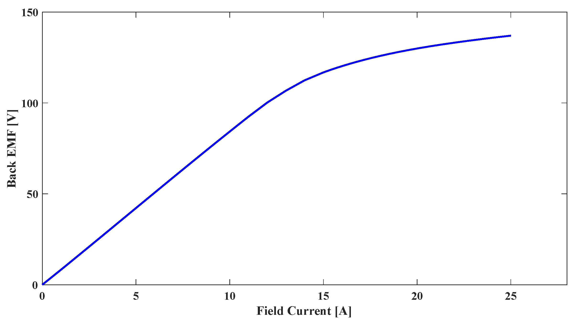
3.1. No Load Analysis

As is discussed above, the rotor of the machine is excited with the induction of harmonics from the armature. If there is no input to the armature winding, then there will be no excitation in the machine. However, magnetization characteristics are drawn by applying different values of current on-field winding and disconnecting the armature winding supply. The characteristics curve between the back EMF and field current of both machines is the same due to same designed parameters, and is given in Figure 8.

3.2. Load Analysis

Initially, both machines are analyzed by supplying the equal currents of 5 Apk to both the 4P and 2P windings of armature using their respective inverters. Since the subharmonic component of MMF in the proposed machine is higher than that of the reference machine, it will induce a higher voltage in the excitation winding of the rotor, which will result in a higher field current. Then, this field current will be able to produce more torque in the proposed machine at the same input to the armature windings. In addition to analysis at the same input as that in the reference machine (say case 1), another case of the proposed machine has also been investigated to consider the comparison on the same output torque (say case 2). The difference in case 2 is that the 2P-winding of the proposed machine is excited by 3.5 Apk, whereas 4P-winding is excited with the same 5 Apk current. The analysis results of these cases in the proposed machine are compared with those of the reference machine.

3.2.1. Flux Density

The magnetic flux density distribution comparison is given in Figure 9a–c. The maximum values for both the reference machine, and case 1 and case 2 of the proposed machines are 1.29 T, 1.62 T, 1.37 T, respectively. It is revealed that the flux density distribution in the proposed machine is slightly higher than that of the reference machine due to higher induction. However, the maximum flux density distribution for both machines is under the saturation level.

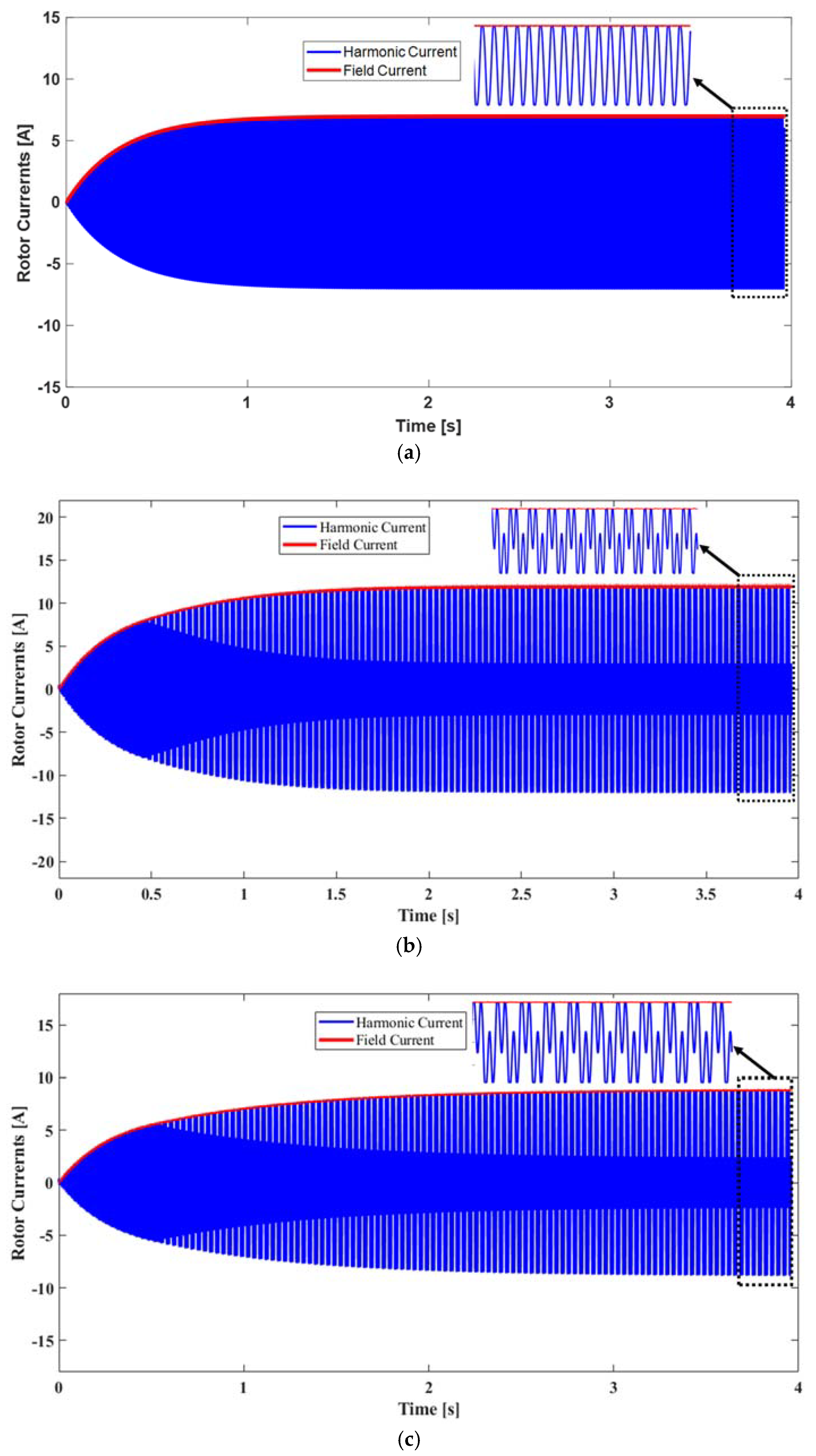
3.2.2. Rotor Currents
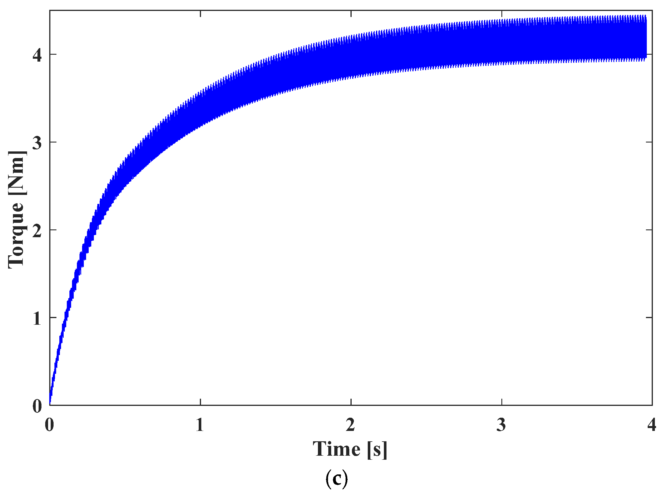
Since 2P armature winding of these machines is being used for the generation of the subharmonic component of MMF, which induces the voltage in excitation winding of the rotor.. This excitation winding is acting as an input source of voltage for the rotating rectifier, which converts this induced voltage into a DC supply to feed the field winding of the rotor. The resulting rotor currents in excitation and field windings of both machines are given in Figure 10a–c. It shows that the average value of field and RMS value of the excitation winding currents for the proposed machine are higher than in the reference machine, indicating better induction due to rich subharmonic component. Now, it can be stated that the current due to induction in excitation winding is providing enough DC supply to the field winding to make brushless operation achievable in the proposed machine.

3.2.3. Torque

The rectified field current is responsible for the rotor magnetic field, which interacts with the main armature field to produce the torque. The torques produced by these machines are shown in Figure 11a–c. It shows that initially, the torque produced by these machines gradually increases from zero and reaches its steady state condition to rated values. The average values of torque are 4.2 Nm, 5.55 Nm, and 4.22 Nm with ripples of 11.84%, 16.43%, and 12.67 % for the reference and proposed machines case 1 and case 2, respectively. It is observed that at the same input, the torque in the proposed machine is 30.9% higher, at the cost of 38% more ripples than the reference machine. This occurs due to the higher subharmonic component of MMF in the proposed machine than that of the reference machine, which will induce a higher voltage in the excitation winding of the rotor and result in a higher field current. This resulting field current is responsible for producing more torque and its ripples. However, in case 2 of the proposed machine, torque and ripples are almost same at the 30% less input to 2P-winding compared to that in reference machine. This confirms that because of better induction, the proposed machine offers the same torque, even at a lesser input current.

3.2.4. Power Losses and Efficiency

The efficiencies of both machines were calculated by considering their copper and core losses. The total losses for the reference and proposed machines case 1 and case 2 are 62.45 W, 144.42 W, and 83.89 W, respectively. These higher losses for the proposed machines are because of higher rotor currents due to better induction. The resulting efficiencies of these machines are 92.69%, 87.81%, and 90.35%, respectively. In case 1 of the proposed machines, the efficiency is significantly lower than the reference machine due to increased losses, while in case 2 efficiency is comparable, even at less input. The overall summary of performance comparison is presented in Table 2. This comparison shows that the proposed machine is able to generate the subharmonic in sufficient amounts, providing better induction to perform the brushless operation using a particular single-phase additional winding on the armature.

4. Conclusions

In this paper, brushless operation of wound-rotor synchronous machine was achieved by using multi-pole windings on the stator and the rotor for the generation of subharmonic component of MMF. This study shows that the proposed machine is providing better induction due to enriched subharmonic component. Utilizing this subharmonic, the proposed machine has a higher torque at the same input current as in the reference machine, while the same output torque can be achieved at 30% less input current than 2P single-phase winding. It means that the proposed machine is able to generate the subharmonic in sufficient amounts to perform the brushless operation, which verifies the effectiveness of the topology using a particular single-phase additional winding on the armature. Thus, the use of a single-phase inverter on 2P-winding of the proposed topology for brushless operation makes it simple, cheaper, and comparable with previously existing brushless topologies. Though the proposed technique has a significantly higher induced current on the rotor owing to the higher subharmonic component, the efficiency is slightly compromised due to increased losses, which can further be improved by improving the design of the machine in the future.

Author Contributions

Conceptualization, M.H. and T.Y.; methodology, M.H. and T.Y.; writing—original draft preparation, M.H. and T.Y.; writing—review and editing, Q.A. and H.-W.C.; funding acquisition, H.-W.C. All authors have read and agreed to the published version of the manuscript.

Funding

This research received no external funding.

Data Availability Statement

Not applicable.

Acknowledgments

This work was supported by the research fund of Chungnam National University, Daejeon, Republic of Korea.

Conflicts of Interest

The authors declare no conflict of interest.

Nomenclature

FEMFinite element analysis
F ( φ , i ) MMF function for the given winding
finput supply frequency
hharmonics
INVsingle phase inverter
INVthree phase inverter
Immagnitude of current
MMFmagnetomotive force
N4Pnumber of turns per phase of 4P-winding
N2Pnumber of turns per phase of 2P-winding
N ( φ ) winding function
ns(h) rotating speed of harmonic
ppole pairs
ttime
ω angular frequency

References

  1. Sun, L.; Gao, X.; Yao, F.; An, Q.; Lipo, T. A new type of harmonic current excited brushless synchronous machine based on an open winding pattern. In Proceedings of the 2014 IEEE Energy Conversion Congress and Exposition (ECCE), Pittsburgh, PA, USA, 14–18 September 2014; pp. 2366–2373. [Google Scholar] [CrossRef]
  2. Du, Z.S.; Lipo, T.A. Efficient Utilization of Rare Earth Permanent-Magnet Materials and Torque Ripple Reduction in Interior Permanent-Magnet Machines. IEEE Trans. Ind. Appl. 2017, 53, 3485–3495. [Google Scholar] [CrossRef]
  3. Barcaro, M.; Bianchi, N. Interior PM Machines Using Ferrite to Replace Rare-Earth Surface PM Machines. IEEE Trans. Ind. Appl. 2013, 50, 979–985. [Google Scholar] [CrossRef]
  4. Barcaro, M.; Bianchi, N.; Magnussen, F. Permanent-Magnet Optimization in Permanent-Magnet-Assisted Synchronous Reluctance Motor for a Wide Constant-Power Speed Range. IEEE Trans. Ind. Electron. 2012, 59, 2495–2502. [Google Scholar] [CrossRef]
  5. Guglielmi, P.; Boazzo, B.; Armando, E.; Pellegrino, G.; Vagati, A. Permanent-Magnet Minimization in PM-Assisted Synchronous Reluctance Motors for Wide Speed Range. IEEE Trans. Ind. Appl. 2013, 49, 31–41. [Google Scholar] [CrossRef] [Green Version]
  6. Hussain, A.; Atiq, S.; Kwon, B.-I. Consequent-Pole Hybrid Brushless Wound-Rotor Synchronous Machine. IEEE Trans. Magn. 2018, 54, 1–5. [Google Scholar] [CrossRef]
  7. Amara, Y.; Vido, L.; Gabsi, M.; Hoang, E.; Ben Ahmed, A.H.; Lecrivain, M. Hybrid Excitation Synchronous Machines: Energy-Efficient Solution for Vehicles Propulsion. IEEE Trans. Veh. Technol. 2009, 58, 2137–2149. [Google Scholar] [CrossRef]
  8. Shushu, Z.; Chuang, L.; Yinhang, N.; Jie, T. A Two-Stage Brushless Excitation Method for Hybrid Excitation Synchronous Generator. IEEE Trans. Magn. 2015, 51, 1–11. [Google Scholar] [CrossRef]
  9. Lipo, T.A.; Du, Z.S. Synchronous motor drives-a forgotten option. In Proceedings of the 2015 Intl Aegean Conference on Electrical Machines & Power Electronics (ACEMP), 2015 Intl Conference on Optimization of Electrical & Electronic Equipment (OPTIM) & 2015 Intl Symposium on Advanced Electromechanical Motion Systems (electromotion), Side, Turkey, 2–4 September 2015; IEEE: New York, NY, USA, 2015; pp. 1–5. [Google Scholar] [CrossRef]
  10. Hussain, A.; Baig, Z.; Toor, W.T.; Ali, U.; Idrees, M.; Al Shloul, T.; Ghadi, Y.Y.; Alkahtani, H.K. Wound Rotor Synchronous Motor as Promising Solution for Traction Applications. Electronics 2022, 11, 4116. [Google Scholar] [CrossRef]
  11. Mi, C.; Filippa, M.; Shen, J.; Natarajan, N. Modeling and Control of a Variable-Speed Constant-Frequency Synchronous Generator With Brushless Exciter. IEEE Trans. Ind. Appl. 2004, 40, 565–573. [Google Scholar] [CrossRef]
  12. Aliprantis, D.C.; Sudhoff, S.D.; Kuhn, B.T. Genetic algorithm-based parameter identification of a hysteretic brushless exciter model. IEEE Trans. Energy Convers. 2006, 21, 148–154. [Google Scholar] [CrossRef]
  13. Ali, Q.; Lipo, T.A.; Kwon, B.-I. Design and Analysis of a Novel Brushless Wound Rotor Synchronous Machine. IEEE Trans. Magn. 2015, 51, 1–4. [Google Scholar] [CrossRef]
  14. Ali, Q.; Bukhari, S.S.H.; Atiq, S. Variable-speed, sub-harmonically excited BL-WRSM avoiding unbalanced radial force. Electr. Eng. 2019, 101, 251–257. [Google Scholar] [CrossRef]
  15. Hussain, A.; Atiq, S.; Kwon, B.-I. Optimal Design and Experimental Verification of Wound Rotor Synchronous Machine Using Subharmonic Excitation for Brushless Operation. Energies 2018, 11, 554. [Google Scholar] [CrossRef] [Green Version]
  16. Gurakuq, D.; Dieter, G. New Self-Excited Synchronous Machine with Tooth Concentrated Winding. In Proceedings of the 3rd International Electric Drives Production Conference (EDPC-2013), Erlangen-Nürnberg, Germany, 29–30 October 2013. [Google Scholar]
  17. Bukhari, S.; Mangi, F.; Sami, I.; Ali, Q.; Ro, J.-S. High-Harmonic Injection-Based Brushless Wound Field Synchronous Machine Topology. Mathematics 2021, 9, 1721. [Google Scholar] [CrossRef]
  18. Ayub, M.; Sirewal, G.J.; Bukhari, S.S.H.; Kwon, B.-I. Brushless wound rotor synchronous machine with third-harmonic field excitation. Electr. Eng. 2019, 102, 259–265. [Google Scholar] [CrossRef]
  19. Bukhari, S.S.H.; Sirewal, G.J.; Chachar, F.A.; Ro, J.-S. Dual-Inverter-Controlled Brushless Operation of Wound Rotor Synchronous Machines Based on an Open-Winding Pattern. Energies 2020, 13, 2205. [Google Scholar] [CrossRef]
  20. Bukhari, S.; Memon, A.; Madanzadeh, S.; Sirewal, G.; Doval-Gandoy, J.; Ro, J.-S. Novel Single Inverter-Controlled Brushless Wound Field Synchronous Machine Topology. Mathematics 2021, 9, 1739. [Google Scholar] [CrossRef]
  21. Bukhari, S.; Ali, Q.; Doval-Gandoy, J.; Ro, J.-S. High-Efficient Brushless Wound Rotor Synchronous Machine Topology Based on Sub-Harmonic Field-Excitation Technique. Energies 2021, 14, 4427. [Google Scholar] [CrossRef]
  22. Rafin, S.M.S.H.; Ali, Q.; Khan, S.; Lipo, T.A. A novel two-layer winding topology for sub-harmonic synchronous machines. Electr. Eng. 2022, 104, 3027–3035. [Google Scholar] [CrossRef]
  23. Rafin, S.M.S.H.; Ali, Q.; Lipo, T.A. A Novel Sub-Harmonic Synchronous Machine Using Three-Layer Winding Topology. World Electr. Veh. J. 2022, 13, 16. [Google Scholar] [CrossRef]
  24. Avon, G.; Bucolo, M.; Buscarino, A.; Fortuna, L. Sensing Frequency Drifts: A Lookup Table Approach. IEEE Access 2022, 10, 96249–96259. [Google Scholar] [CrossRef]
Figure 1. (a) Topology of reference machine, (b) armature winding configuration, (c) rotor winding configuration.
Mathematics 11 01117 g001
Figure 2. Connection of field winding and excitations winding of rotor via a bridge rectifier.
Mathematics 11 01117 g002
Figure 3. For reference machine: (a) MMF Plot and (b) harmonic distribution.
Mathematics 11 01117 g003
Figure 4. Fundamental and subharmonic components of MMF.
Mathematics 11 01117 g004
Figure 5. (a) Topology of proposed machine, (b) stator winding, (c) rotor winding.
Mathematics 11 01117 g005
Figure 6. For proposed machine: (a) MMF Plot and (b) harmonic distribution.
Mathematics 11 01117 g006
Figure 7. Machine model of (a) reference machine and (b) proposed machine.
Mathematics 11 01117 g007
Figure 8. The characteristics curve between Back EMF and field current.
Mathematics 11 01117 g008
Figure 9. The flux density distribution of (a) reference machine, (b) proposed machine case 1, (c) proposed machine case 2.
Mathematics 11 01117 g009
Figure 10. Rotor currents of (a) reference machine, (b) proposed machine case 1, (c) proposed machine case 2.
Mathematics 11 01117 g010
Figure 11. Torque produced by (a) reference machine, (b) proposed machine case 1, (c) proposed machine case 2.
Mathematics 11 01117 g011aMathematics 11 01117 g011b
Table 1. Parameters for analysis of synchronous machines.
ParametersUnitsValues
Speedrpm1800
Rated powerW880
Stator outer diametermm152
Rotor outer diametermm94
Stack lengthmm120
Air gap lengthmm0.5
Number of stator slots-24
Number of rotor slots-04
Stator winding pols-02/04
Rotor excitation/field
winding pols
-02/04
Stator’s No of turns/phase-102
E-Winding total turns-24
F-Winding total turns-248
Table 2. Performance comparison.
ParametersUnitsReference MachineProposed Machine
Case 1Case 2
Input current to 4P-windingApk555
Input current to 2P-windingApk553.5
Excitation winding currentArms5.348.326.17
Field winding currentADC7.0011.948.76
Maximum Flux densityT1.291.621.37
Core lossesW14.4931.8118.69
I2R lossesW47.96112.6165.2
TorqueNm4.205.554.22
Torque ripples%11.8416.1012.67
Efficiency%92.6987.8190.37
Disclaimer/Publisher’s Note: The statements, opinions and data contained in all publications are solely those of the individual author(s) and contributor(s) and not of MDPI and/or the editor(s). MDPI and/or the editor(s) disclaim responsibility for any injury to people or property resulting from any ideas, methods, instructions or products referred to in the content.

