1. Introduction
Due to the constant development of information technologies, the use and distribution of digital multimedia has become part of the everyday life of today’s society, which has allowed digital images to be widely used in entertainment, education, and even business applications [
1,
2,
3]. However, all kind of images stored in the cloud can be easily copied, modified or falsified in an unauthorized way, during the different stages of transmission and storage; in some cases, the information associated with their files can be manipulated, as illustrated in
Figure 1. To provide an additional security mechanism capable of dealing with this problem and thereby protect the visual content, intellectual property, and associated information, as well as authenticate the images in question, various reversible data hiding (RDH) [
4] approaches have been presented in the literature as a promising solution, such as reversible data hiding in the encrypted domain (RDH-ED) methods.
Although different data hiding approaches have been presented in the literature, such as steganography and digital watermarking [
1,
2,
3,
5,
6,
7], developed with the purpose of protecting the image and its intellectual property, most of the methods used introduce permanent distortions in the visual content, so that some are not suitable for implementation in images of sensitive nature, since they contain elements that are usually used for military, forensic, medical, or commercial use and are strictly forbidden to present any modification in their content. On the other hand, to counteract any visual degradation in images, RDH schemes hide additional information within a medium and can restore the processed signal to its original state after the extraction of the data that has been inserted [
4,
8,
9,
10,
11,
12,
13,
14,
15].
Driven mainly by the need of privacy preservation in cloud platforms, the paradigm known as RDH-ED emerges [
8,
9,
10,
11,
12,
13,
14]. This data hiding method mainly aims at inserting additional information inside encrypted data without revealing the plaintext content, so that the receiver can recover the additional bits error-free, thereby restoring the medium to its original state. With hidden data, it is possible to distribute additional information covertly, whether it is related to the image or not, which can also be used to authenticate the image and protect intellectual property.
A crucial feature present In RDH-ED schemes is the participation of three entities: content owner, data hider, and receiver. In the literature [
4], the content owner has been defined as the one who owns the original multimedia, in this case images, in addition to being the one who encrypts the pixels that compose the image and provides the information to be hidden. Subsequently, the data hider receives the encrypted media and, without knowing its plaintext content, oversees embedding the additional data into the media. Finally, the receiver is the one who will be able to extract the additional data or restore the image to its original state. Usually in the literature, the content owner is considered as the user who creates or captures an image and encrypts the additional data, while the data hider is the cloud storage service provider; in this way, the data hiding is performed without exposing the visual content of the image or the data embedded into it, ensuring that only the content owner and a legitimate receiver will be the only ones who will know what the image represents and the additional information it contains, without affecting the process of creating the encrypted image and marked with hidden data. To perform the operations of encryption, decryption, as well as embedding and extraction of additional bits, the RDH-ED methods employ encryption and data hiding keys, respectively. So, obtaining a directly decrypted version of the image or approximation requires the encryption key, while the data hiding key will only allow extraction of the hidden information, meaning that the receiver needs both keys to retrieve both the hidden information and the original media. This allows a legitimate receiver with the marked and encrypted image to access only the content according to the security keys it possesses; this feature of RDH-ED schemes is known as separability. Later, the authors of [
8] presented the concept of complete separability; this property refers to the ability of the algorithm to allow the receiver to retrieve the information and image, not only from the encrypted version of the image, but also from the plaintext domain of the approximate image, i.e., directly decrypted.
Considering the current state of the art, existing RDH-ED schemes can be classified into three categories: (a) vacating room before encryption (VRBE) [
10], where the space or region where the additional bits will be embedded is designated before the encryption process; (b) vacating room after encryption (VRAE), the embedding region is defined after encrypting the image [
9,
11]; and (c) directly embedding after encryption [
12,
13,
14], unlike the previous methods, the space where the information is embedded is not designated before or after encryption, but is created during this process. Although a considerable number of RDH-ED schemes have been presented so far, only a few of them feature full separability; for the sake of brevity, the most notable works on fully separable RDH-ED schemes recently reported in the literature are presented in
Table 1.
On the other hand, in 2016, the authors of [
15] presented a novel RDH scheme whose data hiding was based on the CDM technique, while most of the algorithms published up to that time were developed based on lossless compression algorithms, histogram modification, and difference expansion, also known as prediction error expansion. The results obtained by CDM showed superior performance compared to conventional techniques at that time, reaching peak signal to noise ratio (PSNR) values of 38.10 dB with embedding rates (ER) of 1 bit per pixel (bpp); however, the CDM scheme was not designed to operate in the encrypted domain. The present work proposes an RDH-ED scheme which allows storing additional data inside encrypted digital images, so that only a legitimate receiver can access the hidden data or restore the image to its original state, according to the security elements it provides, either from the encrypted or approximate version of the processed image. For this purpose, the image is encrypted with the AES algorithm in its counter (CTR) mode [
16,
17], while the additional data are embedded through the CDM technique [
15].
The main contributions of the RDH-ED scheme developed in this work are:
Implementation of CDM embedding algorithm [
15] in a complete separable RDH-ED scheme, without affecting its overall functionality, while providing the method with high hiding capacity and allowing the generation of high visual quality approximations.
Improved security of the RDH-ED scheme by employing the AES algorithm in its CTR mode to encrypt the digital images, and due to the use of multiple data hiding keys.
Adaptation of the implementation of the AES-128 cipher [
18] in CTR mode during embedding space reservation before encryption, to make the developed proposal completely separable.
Increased data hiding capacity by improving image preprocessing [
19], which reduces the auxiliary information required by this process, and at the same time prevents overflow/underflow issues from occurring.
Improved versatility of implementation of the proposed scheme in images with depths greater than eight bits/pixel, due to CDM embedding not being a method dependent on the spatial redundancy of the image.
Considering design conditions and contributions of the proposed RDH-ED method, the experimentation presents an implementation scenario in digital medical images, whose format is defined by the Digital Imaging and Communication in Medicine (DICOM) standard [
20]. Unlike natural images, the different DICOM imaging modalities present resolutions higher than eight bits/pixel; they also contain sensitive information about the patient’s condition, which can be used in health insurance fraud, identity theft, and even affect diagnosis and treatment [
5,
6,
7]. Due to their sensitive nature and own characteristics, conventional RDH-ED algorithms are not able to operate directly on DICOM imaging, so only a few solutions based on RDH methods for encrypted medical images have been presented in the literature [
21,
22,
23,
24,
25,
26], whose purpose is to protect the privacy of the visual content of the medical image and facilitate access to patient information, without exposing its content to unauthorized users.
The content of the article is organized as follows:
Section 2 describes the elements that make up the scheme, as well as the details of the different phases of the developed method. The results obtained in the experimental tests and parameter settings are presented in
Section 3. In
Section 4, the performance comparison of the proposed scheme with respect to the state of the art is carried out. Finally,
Section 5 concludes this work.
2. Materials and Methods
To develop an RDH-ED method able to generate directly decrypted images of high quality with a high data embedding capacity, the CDM algorithm [
15] was employed in conjunction with an adapted implementation of the AES-CTR cipher [
16,
17,
18], so that the security level and the complete separability of the algorithm are ensured.
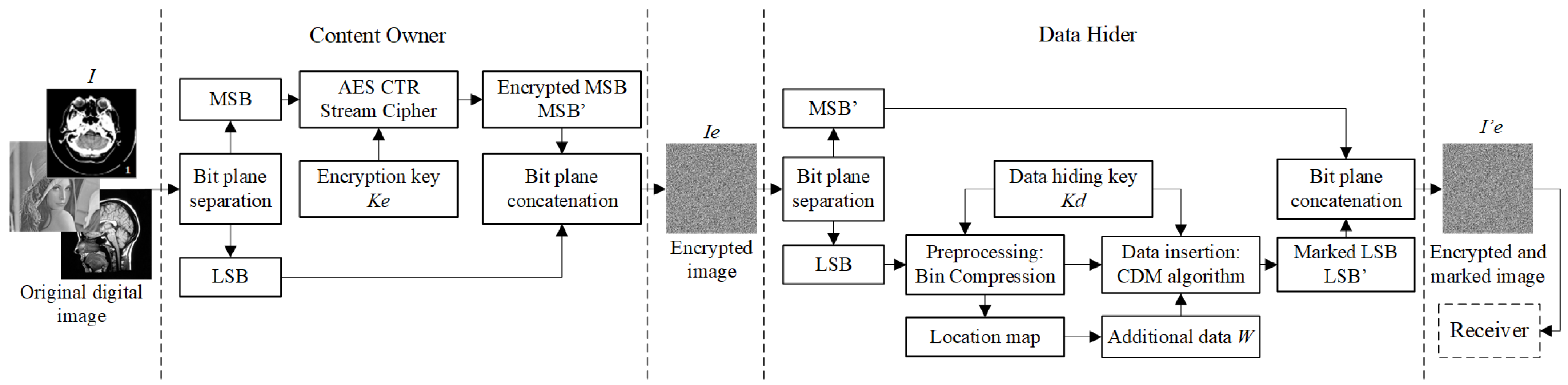
For this purpose, the process phases of the proposed scheme are divided according to the entities involved: (a) the content owner encrypts the image and reserves the LSB planes where the data will be stored, (b) the data hider embeds the additional bits into the encrypted image in the designated space, and (c) in the last stage, the receiver is able to recover the hidden data and restore the image completely. Additionally, the data hider will preprocess the image to increase the capacity and avoid pixel saturation problems caused by embedding bits via CDM. The whole procedure described above is shown in
Figure 2 and explained in detail below.
2.1. Image Encryption: Adapted AES-128 Algorithm
Considering the design conditions that allow access to the hidden content and to the image itself independently from the image decryption, the stream cipher has been tailored to allow extracting the modified bits from the image, either from the plaintext or from the cipher domain. The developed proposal uses the AES-128 algorithm in its CTR mode of operation due to the high efficiency of its implementation in RDH-ED schemes reported in the literature [
18], while providing the method with a reliable level of security, in addition to presenting the ability to simulate the operation of a stream cipher. However, the AES-CTR algorithm can be replaced by any other stream cipher algorithm without affecting the operation of the developed scheme.
The image encryption process is described below:
Read the digital image I with M1 × M2 dimensions, and eight bits/pixel of grayscale resolution in the case of natural images, or with higher resolutions for other image modalities. This means that natural images are made up of pixels , while other modalities will have higher pixel intensities, with .
The decimal values of each pixel are converted to their binary format to facilitate the manipulation of the bit planes of each pixel.
Each binary representation is partitioned so that the most significant bit planes (MSBs), designated as , are separated from the least significant bits . In the case of natural images, the first 2 MSB planes will be used, while the rest of the planes will be considered as LSB.
To obtain each encrypted pixel the AES-CTR algorithm is only applied to the bit planes , using the encryption key to produce the encrypted MSB planes . If not specified, the key used by the AES algorithm is assumed to be 128 bits long.
Subsequently, the encrypted most significant bits of each pixel are concatenated with the corresponding least significant bits which have not been modified in any way.
The values obtained from the concatenation are converted from binary to decimal format to generate the encrypted pixels .
In this way, by repeating the procedure described from point 2 to 6 for each of the pixels that make up the image, the encrypted version of the digital image I is constructed.
The implementation of the tailored cipher for each pixel is given by Equation (1):
where the encryption function
indicates all the operations described above. The encrypted bits
are obtained by an XOR operation between the
of the plaintext and the pseudo-random bit stream generated by the AES-CTR stream cipher and the cipher key
, to later be concatenated with the unmodified planes
to form the pixels
.
With the implementation of this method, illustrated in
Figure 3, all the pixels of the image
keep the LSB planes free of modifications; this means that it is possible to manipulate these bits without affecting those that have been encrypted. From the application of the proposed scheme, the encrypted image is defined by Equation (2):
The number of bit planes selected as MSBs and LSBs is a parameter required by the data hider to embed the additional data into the corresponding bits; this ensures that the plaintext content of the image will not be exposed, either at the time of data embedding or extraction, respectively.
The preservation of the original resolution of digital images, provided by this adaptation of the AES encryption, is also reflected in the file size and avoids any possible error in the display of the encrypted image. It should be noted that the method described in this section is not only applicable to the CTR mode of operation, but also to the OFB mode of the AES cipher.
2.2. Data Hiding: Insertion Based on CDM
Once the medical image has been encrypted using AES-CTR algorithm, the data hider is able to hide the data inside the encrypted medical image, even if it does not know its content. The CDM technique [
15] is used to insert the additional data, as it demonstrated a high capacity to hide data within images without significantly affecting their visual quality, so that only the LSB planes are modified during this process.
The data hiding keys Kd correspond to positive integers that are part of the parameters required by the CDM technique and are used in the following process:
Initially, Ks spreading sequences are selected from the Walsh–Hadamard matrix, , which are mutually orthogonal to each other and whose elements consist of the same number of “1” and “−1”. The value of Ks corresponds to the number of bits that will be embedded into the image; in this scheme, the lengths of the sequences Si used are 2 and 4 elements.
Additional data to be hidden are designated as
made up of bits
; these bits will be modified according to Equation (3):
Consequently, the bits to be inserted will be where .
- 3.
As in the image encryption stage, the bits of each pixel of the image Ie are separated into the encrypted MSB planes and the planes . Subsequently, the bits of the LSB planes of the image I are transformed into their decimal format and are used to build the matrix ILSB.
- 4.
The matrix ILSB is decomposed into vectors , whose length is equal to that of the sequences Si. For this purpose, adjacent and non-overlapping elements of the matrix ILSB are selected as the elements .
- 5.
In such a way that the bits
will be embedded into LSB planes, when evaluating the vectors
according to Equation (4):
where
is the gain factor and the evaluation parameter
. Embedding intensity is controlled by the value of α; as its value increases, the number of vectors suitable for embedding will also increase and the degradation will be more perceptible in the directly decoded image.
- 6.
The matrix of marked LSBs I′LSB is obtained by replacing the vectors by their marked versions . The process described in steps 4 and 5 is iterative, so it can be applied again to already modified vectors, thanks to the fact that the sequences are mutually orthogonal and the cross-correlation of two different sequences is 0; therefore, the bits can be embedded multiple L times in the same vector without interfering with each other.
- 7.
Once data embedding has been completed, the values of the matrix I′LSB are transformed to binary format; the obtained bits are concatenated with the corresponding planes to obtain the marked and encrypted image .
As can be observed in Equation (4), only those vectors that meet the condition are considered suitable to contain additional bits. On the other hand, pseudo bits will be inserted in the vectors that do not meet this condition, i.e., the vectors will be modified without containing any bit.
The data hiding key
Kd, required to retrieve the hidden bits corresponds to the embedding parameters: number of LSB planes, α, the sequences
, the length
, and the number of iterations
L that the algorithm runs. It is noteworthy to mention that the additional bits can contain cryptographic digests [
16,
17] that allow verifying the integrity of the image, copyright data, sensitive metadata, and even information not associated with the image, so that it is distributed secretly.
2.3. Image Preprocessing: Bin Compression
Although data embedding using the CDM technique does not generate a high level of visual degradation in relation to its capacity, compared to other methods, it does cause a displacement of pixel intensities towards the extremes in each of its iterations. This means that the method will cause pixel saturation at low and high intensities; this problem is also known as underflow and overflow.
To counteract such effect, an improved version of preprocessing reported in [
19] is employed; this technique is applied prior to data insertion and is described below:
The purpose of this processing is to shift the intensities of the pixels close to the minimum and maximum possible values, which depend on the number of LSB planes selected for data hiding. First, the histogram is obtained from the matrix ILSB of decimal values of the LSB planes, the same that will be used in the CDM embedding and is obtained in step 3 of the data hiding stage.
The number of values at each extreme to be shifted to the center is selected and designated as N, i.e., there will be N number of empty bins on the left side and N number of empty bins on the right side of the histogram. This parameter also refers to the maximum possible displacement that some pixels will have.
In order to modify the smallest number of pixels, the number of pixels belonging to three intervals of the histogram will be evaluated. For this purpose, the frequencies of occurrence in the following intervals will be added: D1 = [limInf, limInf + 4N − 1], D2 = [limInf, limInf + 2N − 1] + [limSup − 2N + 1, limSup ] and D3 = [limSup − 4N + 1, limsup], where limInf is the lowest possible intensity value and for all images will always be equal to 0, while limSup will be the maximum value that a pixel can take and will depend on the number of selected LSB planes.
Once the calculation of the previous step has been performed, the interval containing the smallest number of pixels will be selected and one of the following three processing steps will be performed.
In case the smallest number of pixels is close to 0, all pixels with an even value in the interval D1 = [0, 0 + 4N − 1] will have 1 added to them, combining them with the odd intensities; in case the pixel is odd, its value will not be changed. To differentiate the modified values, a location map will be generated, where the modified pixels will be identified with a value of 1, and those that are not, with a value of 0.
The odd bins in the interval [0, 0 + 4N − 1] are shifted towards the center, so that the empty bins are eliminated.
Once there are 2
N empty bins on the 0 side, all pixel intensities will be subtracted
N to center the histogram, as shown in
Figure 4, thus obtaining
N empty bins at each end.
- 8.
If the smallest number of occurrence frequencies is from the interval D2, then the even pixels in the interval [limInf, limInf + N − 1] will have 1 added to them, while the odd pixels in the interval [limSup − N + 1, limSup ] will have 1 subtracted from them. Pixels present in these intervals that have been modified are recorded in a location map as 1, while those that retain their original value will be recorded as 0.
- 9.
The evaluated intensities are shifted towards the center, eliminating the presence of bins with frequency of occurrence 0, so that there will be
N empty bins on each side of the histogram. An example of this preprocessing is presented in
Figure 5.
- 10.
Finally, in case the lowest pixel concentration is on the far right, the odd pixels in the interval D3 = [limSup − 2N + 1, limSup] decrease their value by 1 and are combined with the even intensities. As in the previous cases, the modified and unmodified pixels are recorded as 1 and 0 in the location map, respectively.
- 11.
The new even bins in the interval D3 move towards the center, eliminating the empty spaces that appeared between them.
- 12.
Finally, all the pixels of the image are added
N to shift the histogram towards the upper limit and create
N empty bins on each side of the histogram, as shown in
Figure 6.
- 13.
The generated location map is compressed using the Huffman algorithm [
27] and added to the message
W to be embedded into the image with the CDM technique, as part of the control information. The matrix obtained from all this processing is used as
ILSB during the data hiding stage.
The process described above is applied only to the LSB planes selected by the content owner, either before or after the encryption, if it is performed prior to the whole embedding process. Therefore, the maximum number
N of bins that can be emptied at the ends of the histogram will depend on the number of possible intensities that the pixels can present, given by the LSB planes selected for the insertion. Likewise, the value of
N will be obtained from the insertion parameters
α and the number of iterations
L executed by the CDM algorithm, since they control the displacement of the pixel intensities. Considering the embedding behavior, the value of
N is calculated according to Equation (5):
where
n is the number of bit planes composing the processed image. The condition stated in Equation (5) is because only a quarter of the total possible intensities at each end can be emptied, without the intervals
D overlapping each other. Otherwise, the location map could not be employed to correctly restore the original positions of the preprocessed pixels. The number
N of empty bins generated by the preprocessing is also interpreted as the maximum displacement value that some pixels of the processed matrix will present after data hiding.
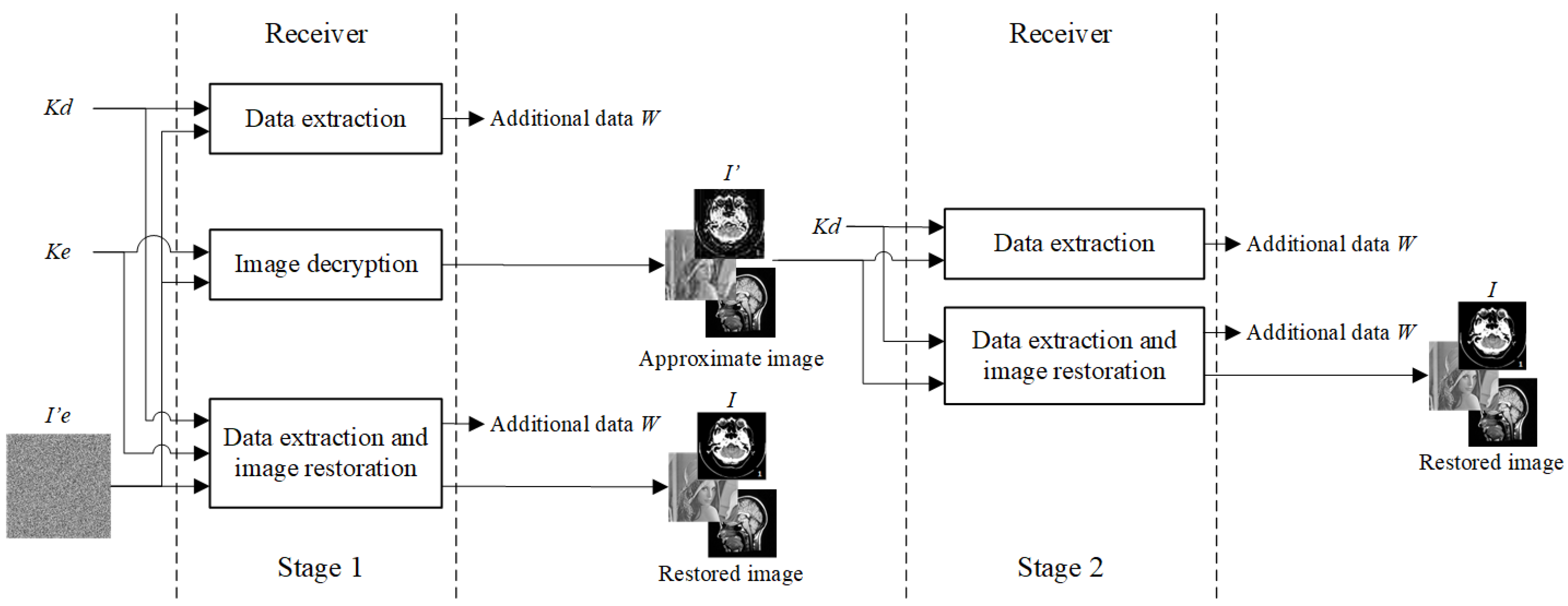
2.4. Receiving Cases: Hidden Data Recovery and Image Restoration
In the final stage, a legitimate receiver with the image
will have access to the different elements, depending on whether it possesses the encryption key
Ke or the data hiding key
Kd. Thanks to the complete separability, it is possible to extract the data and recover the image from the encrypted domain
Ie or from the plaintext of the approximate image
I′. The cases available at the reception are presented in
Figure 7; the first stage corresponds to the normal separability property and is carried out from the encrypted and marked version
. On the other hand, the second stage is only possible in complete separable RDH-ED schemes and allows to recover the data or the image from the approximation
I′ later when the receiver considers it necessary. The specific operations for each case are explained below.
2.4.1. Extraction of Data from the Encrypted Domain
In case a receiver obtains the image created using the proposed scheme and knows the key Kd, he will have access to the additional data previously embedded and free of errors, without being able to decrypt the image. For this purpose, the following procedure is required:
At reception, read the digital image and the pixels of the image are transformed into its binary format to separate them into the marked bit planes and the encrypted bits . Subsequently, the marked LSB planes are converted to their decimal format to generate the matrix I′LSB.
As during data hiding, the adjacent elements of the matrix I′LSB are selected to form vectors , whose length is equal to the length of the sequences Si used in the embedding.
Each vector
is evaluated to determine if it contains a bit
, as long as it meets the condition in Equation (6). For this purpose, the receiver must know the sequences
used in each iteration and the value of α.
In case of fulfilling the previous condition, the hidden bit
is extracted by Equation (7). The operation
sign(·) will result in 1, if the evaluated element is positive. Otherwise, the result will be −1.
The above process is repeated for all the marked vectors
, according to the number of times
L that the algorithm has iterated during the data hiding phase. The recovered bits
are modified according to Equation (8) to obtain the previously embedded additional data
W.
2.4.2. Obtaining the Image Approximation
When the receiver has the image with the encryption key Ke, it is only able to directly decrypt the image and generate an approximate image of the original, since it will still contain bits modified by the additional data. This process is described below:
To obtain the directly decrypted version
of the image
, the process is similar to the one described in
Section 2.1 for image encryption.
The MSB planes are separated from the LSB planes of the marked and encrypted image to obtain the most significant bits of the encrypted pixels .
Since the presented encryption method is completely reversible, to decrypt the image and obtain the original plaintext version, the inverse process is performed for each bit of
, according to Equation (9):
where the decryption function
means that the pixels go through the same procedure given by Equation (1), except that the AES-CTR algorithm will operate as the decipher.
Once the bits have been decrypted, the original MSB planes are concatenated with the marked LSBs . Thus, the approximate version of the image I′ is obtained, since only the MSBs of the image have been restored to their original state without revealing the additional bits or exposing them to any modification.
2.4.3. Image Recovery from the Encrypted Domain
If both the encryption key Ke and the data hiding key Kd are present at the reception, the additional data can be extracted, and the image can be restored losslessly from the encrypted and marked version . The recovery process is described as follows:
In this way, the modifications caused by the insertion of bits and pseudo bits by the CDM algorithm are reversed.
- 3.
Vector restoration must be repeated according to the number of times L the data embedding has been iterated. Once the bit planes have been restored to their pre-embedding values, preprocessing must be reverted if it was used.
- 4.
To restore the LSB planes to their initial values, it must be known the interval of the histogram that presented the lowest concentration of pixels. Subsequently, the bins are shifted in the opposite direction to that described in the preprocessing stage to create the empty spaces in the corresponding bins.
- 5.
The location map is used to identify the modified values and move them to their corresponding position, so that all values return to their initial state and the LSB planes are obtained with their original values.
- 6.
As in the case of obtaining the approximation, the bit planes are decrypted using the encryption key Ke and Equation (9) to obtain the decrypted .
- 7.
Finally, the image is reconstructed by concatenating the recovered with the corresponding decrypted MSB planes , and then transforming the bits to their decimal format. Thus, the image I is completely restored to its original state.
Note that both additional data extraction as well as restoration of LSB planes can also be performed right after encryption.
2.4.4. Extracting Data from the Plaintext Domain
After the first stage of reception, a receiver will still be able to extract the additional data W, even if it does not have the encrypted and marked image , as long as it has the data hiding key Kd. Unlike the previous three options, this case requires the approximation I′, obtained from the process described in the second case. For this purpose, the same procedure described in the data extraction from the encrypted domain will be applied to the directly decrypted image I′. This is because the implemented CDM embedding is completely independent of the whole AES-CTR encryption process, which allows keeping the pixels with hidden bits even after decryption.
2.4.5. Image Restoration from the Plaintext Domain
With the approximation of the image I′ in conjunction with the key Kd, the receiver not only has the ability to extract the additional data, but can also restore the image as if it had both keys: Ke and Kd. This operation can be considered as an extension of the previous case. For this purpose, the procedure described in steps 1 to 5 of the case of image recovery from the encrypted domain is performed on approximation I′ to recover the bits . Finally, the restored LSB planes are concatenated with the already decrypted MSB planes from the directly decrypted image I′, and by converting the resulting bits to their decimal format, the completely restored image I is obtained without any loss.
3. Results
To determine the performance of the proposed RDH-ED scheme, the embedding capacity achieved in the processed digital images will be evaluated, as well as the visual quality of the directly decrypted versions. The results obtained during the experimental tests are presented in this section.
3.1. Experimental Environment
The experimental tests were applied to the image set provided by the database [
28], which consists of digital grayscale images with a depth of eight bits/pixel, i.e., the natural images used are made up of pixels
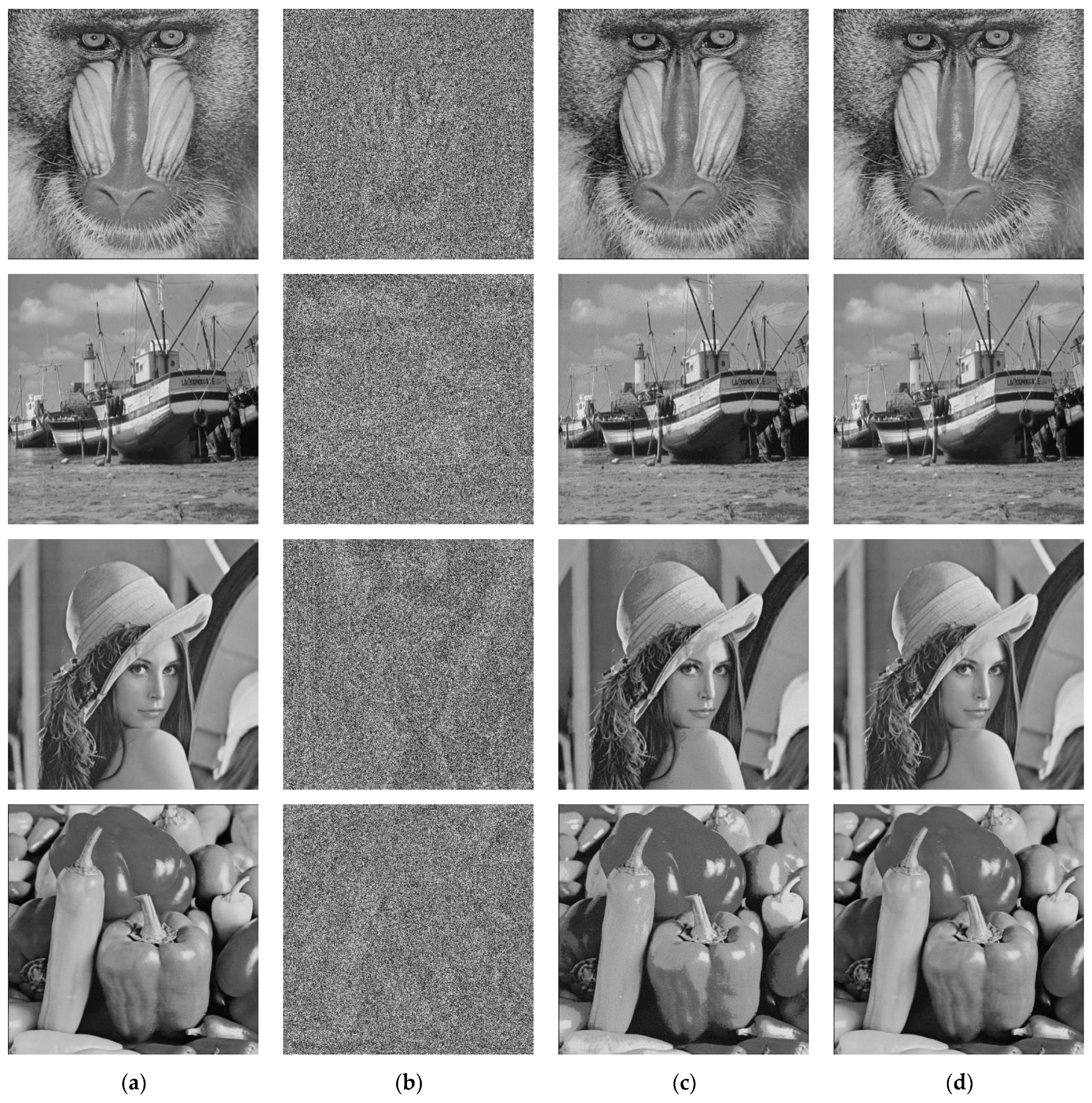
. This set contains 14 images with a size of 256 × 256 pixels, 26 have dimensions of 512 × 512, and 4 with dimensions of 1024 × 1024. Some samples of the images generated from the implementation of the developed scheme are presented in
Figure 8 for different ER values.
The development of the proposed scheme, as well as the experimental tests, were performed on a personal computer with Windows 10 Pro © operating system, Intel © Core ™ i7 processor (2.66 GHz) and 8 GB of RAM memory.
The software used in this process was MATLAB © R2022b. With this equipment, the average preprocessing time for 256 × 256, 512 × 512, and 1024 × 1024-pixel images was 0.045, 0.19, and 0.8 s, respectively; while both encryption and decryption were performed in an average of 3.42, 11.87, and 41.06 s, for each size; the time it took for the CDM algorithm to perform an iteration is 0.025, 0.096, and 0.403 s for the three corresponding dimensions. On the other hand, in the receiver phase, the average data extraction duration was 0.023, 0.102, and 0.31 s for the respective sizes; image restoration took 0.036, 0.129, and 0.454 s; and finally, the average time to revert image preprocessing was 0.039, 0.131, and 0.46 s. Although the content of each image is different, for the same size, the recorded time data turned out to be highly approximate to each other; this resulted in obtaining average time values that adequately reflect the duration of each process for a certain number of pixels, regardless of their intensity values. Additionally, as can be seen for images with dimensions of 256 × 256, the average times are usually a quarter of the corresponding time for images of 512 × 512 pixels, since they contain 65,536 and 262,144 pixels, respectively. This is also observed in images with a size of 1024 × 1024, since they present four times greater time values compared to those of 512 × 512 images and contain four times more pixels.
3.2. Parameter Settings
Taking as a priority the number of bits that can be hidden within an image, as well as the generation of approximations with high visual quality, in the literature, RDH-ED schemes are evaluated in terms of their capacity and imperceptibility. Therefore, the parameters were selected to achieve the maximum embedding capacity while inducing the least possible amount of visual degradation.
For the purposes of the proposed scheme, the AES cipher will operate in its CTR mode, whose encryption key will be 128 bits long. In RDH-ED schemes, there is a mandatory interaction between the encryption and data hiding, while in complete separable methods, they do not interfere with each other. However, in this proposal, there is an indirect trade-off between the cipher and the CDM algorithm, depending on the number of bit planes selected for each task. The more bits considered as MSB and used in encryption, the less the original visual information will be preserved and the image will be more unreadable, and in return, the number of bits that can be embedded will be reduced. On the other hand, when a greater number of planes is used as LSB for data insertion, there will be more pixels suitable to contain information and thus a higher capacity will be achieved, but some image details might be visible even after encryption. Based on the experimental tests to obtain acceptable values of both capacity and imperceptibility, only the first 2 MSB planes were designated to perform the encryption, while the other 6 bit planes were considered the LSBs that will contain the hidden data. Since 6 bit planes will be used for data hiding, the CDM embedding will be performed on values within the range of . Therefore, and according to (5), N can only have a maximum value of 16 to ensure that the preprocessing can be reversed correctly. Additionally, for D intervals defined by the preprocessing, limSup = 63 will be used for natural images, while for images with depths greater than eight bits/pixel, it is recommended to use limSup = 255.
Considering the restriction of Equation (5) and the maximum value of N, the product of the parameters of α and
L must not exceed 16, i.e.,
αL ≤ 16. Therefore, in bit insertion performed for the experimental tests, all possible combinations of values of α and
L that meet the previous condition will be used. Another essential element for CDM embedding is the spreading sequences
Si, whose length
l defines the maximum embedding rate that can be achieved in one iteration. The lengths proposed by [
15] are two, four, and eight elements; employing these values means that in each iteration, it will be possible to embed one bit for every two, four, and eight pixels, respectively. The tests showed that
l = 2 considerably reduces the number of pixel vectors suitable for insertion, because with only two values, it is difficult to fulfill the condition given by Equation (4). The same is true when
l = 8 or greater, since it is difficult for the set of values that forms each vector to meet that condition, in addition to the fact that embedding 1 bit for every 8 or 16 pixels reduces the maximum capacity per iteration to 0.125 and 0.0625 bpp, respectively. Hence, the length used by this scheme is
l = 4, which limits the maximum capacity per iteration to 0.25 bpp, and the sequences
Si used were
S1 = [1, −1, 1, −1],
S2 = [1, 1, −1, −1], and
S1 = [1, −1, −1, 1]; these sequences are repeated after every three iterations. It is worth mentioning that the maximum capacity is an ideal case where all pixel vectors are suitable for data embedding, so this will hardly occur in a real scenario.
To facilitate the understanding of the parameters, as well as to visualize the effect of pixel displacement related to N, the following example is presented. Supposing that the pixels of the Airplane image make up the vector V1 = [177, 174, 172, 175], the bit to be inserted is b1 = 1, the spreading sequence used is S1 = [1, −1, 1, −1], and parameter α = 1. In order to perform the embedding of the first iteration, it is evaluated whether V1 is suitable to store bits according to Equation (4); the parameter is calculated, as well as the cross-correlation between V1 and the sequence , . Since the condition is fulfilled, the bit is embedded into the evaluated vector, and the marked vector is obtained. As can be seen, each intensity value varies by one unit, due to α = 1.
Although the experimental tests were performed on the entire image base of [
28], data obtained from the most used classical images in the literature by the most recent RDH-ED schemes will be mainly presented. It should be noted that the previously defined parameters are selected to obtain the highest performance of the proposed method. However, other combinations of parameters can be used and be fully functional, which increases the number of possible security keys that can be used both in the encryption and data hiding process.
3.3. Method Capacity
Thanks to the characteristics of CDM embedding, bit insertion can be performed iteratively without the risk of hidden data from a previous iteration interfering in the next one; this allows hiding a greater amount of information within the same pixels and increases the total capacity of the method. To show the behavior of the proposed method,
Figure 9 shows the number of bits that are hidden in each iteration of the same embedding process for the test images: Lena, Boat, Man and Baboon, using values of
α = [1, 5] for all the allowed values of L, in accordance with the previously stipulated restrictions.
As shown in
Figure 9, the parameter α is directly proportional to the number of bits embedded in each iteration; this is because a higher value of α will make it easier for the pixel vectors
to meet the condition
defined in Equation (4), which in turn makes them suitable vectors for embedding. Unlike other iterative data hiding methods, where the number of bits to be inserted is gradually reduced in each iteration, the number of bits inserted by the CDM algorithm is greater in every third iteration with respect to the previous two and is considerably reduced in the next iteration. For example, in the Lena image, 40,743, 36,407 and 46,336 bits are hidden in the first iterations, while in the following three iterations, 16,176, 14,049, and 17,889 bits are inserted; although fewer bits are inserted in iterations 4, 5, and 6 than in the first three, they presented the same behavior of increase in the number of bits embedded in the sixth iteration.
This effect occurs because the spreading sequences
are mutually orthogonal, causing some of their elements to cancel each other out between each iteration while reducing visual distortion. Therefore, the cancellation of elements between a first
and a second sequence
will reverse some of the modifications produced in the pixel intensities, increasing the number of vectors
suitable for the third insertion. On the other hand, to determine the effects of the embedding parameters on the method capacity for different types of images, the bit embedding rate was evaluated in relation to α and
L; a sample of the results is presented in
Figure 10. Unlike the previous figure, where the data for each α value belong to the same embedding process, in
Figure 10, each value presented corresponds to the capacity achieved by an individual embedding performed with the corresponding α and
L parameters, which allows a better representation of the capacity behavior with respect to the different data hiding keys used.
It is clear from the graphs shown that data embedding capacity varies considerably for each combination of α and L values. Additionally, the embedding rates achieved by one image can become very different from those obtained by another image, even when the same parameters are used.
This demonstrates that, even if the same operations are performed on each image, the number of bits inserted will depend on the pixel intensities that make up each vector and can be controlled to some extent by the parameters of the CDM algorithm.
The maximum capacity values reached by the Lena, Man, and Boat images are 0.929, 0.874, and 0.866 bpp, respectively, and were obtained with parameters α = 2 and L = 8, while the Baboon presented a maximum capacity of 0.684 with values α = 4 and L = 4. It is true that the proposed CDM embedding is not performed directly on the pixel intensities. Even so, the image textures will be partially reflected in the values obtained from the selected LSB planes. Considering the observations made, it was determined that images presenting many regions with smooth textures will tend to present their maximum capacity with values α = 2. Whereas images with complex textures will be more likely to reach their maximum capacity when α = 4, due to the considerable intensity variations of the neighboring pixels, i.e., α should take a higher value to increase the probability that the pixels are suitable to carry additional bits.
However, increasing the values of the parameters α and L does not imply an increase in the capacity; in some cases, the capacity may be even lower, since by changing the value of N, the preprocessing will generate different initial values on which the data embedding will be performed. It should also be kept in mind that increasing α restricts the number L of possible iterations, which in turn reduces the maximum possible capacity.
To better demonstrate the relationship of the parameters with the capacity, the Boat image will be taken as an example, which reaches a capacity of 0.777 bpp with 5 iterations when using
α = 3, while using
α = 5, it is only possible to perform 3 iterations and the ER obtained was 0.655 bpp. In both cases, the image was preprocessed with
N = 5 × 3 = 15; however, the maximum possible capacity for
L = 3 is 0.75 bpp, while for
L = 5, it is 1.25 bpp. On the other hand, looking at
Figure 9, in the first three iterations, the number of bits inserted with
α = 5 is higher compared to the rest of the
α values. In summary, increasing the value of
α will result in an increase in the number of bits embedded per iteration, but the maximum possible capacity will depend on the number of iterations
L that the algorithm executes.
Another factor that should not be forgotten is the control information that is created during preprocessing, whose length in bits will depend on the value of
N, the decimal values of the image LSBs, its distribution in the histogram, and on the compression rate that the Huffman algorithm can obtain [
27]. In this scheme, the control information is included in
W since it is required to restore the pixels to their original values. It should be noted that the values presented in
Figure 9 and
Figure 10 correspond to the total embedding capacity of the method, i.e., the capacity required to store the control information has already been subtracted from these values.
3.4. Imperceptibility of Approximations
Another essential aspect that is evaluated in RDH-ED schemes is the visual quality of the directly decrypted images with respect to their original version, in relation to the obtained embedding rates. To evaluate the imperceptibility of the method in the approximations, the peak signal to noise ratio (PSNR) metric [
29] will be used, which has been widely employed in the literature to determine the level of distortion of the carrier signal with hidden data and is defined in Equation (11):
In the context of the developed scheme, I(x, y) refers to the pixels of the original image, I′(x, y) are the pixels of the image with hidden data, and the dimensions of the evaluated image are designated as M1 and M2. The higher the value of PSNR, the lower the presence of modifications in the evaluated image.
However, the structural similarity index (SSIM) metric [
30] will also be used to assess the visual quality of the approximate versions more accurately, since it allows to determine the similarity between two images by quantifying the images quality more consistently to human visual perception than the PSNR; this metric is defined by Equation (12).
As in Equation (11), the original image and its approximate version are designated as
I and
I′, respectively, while
µI and
µI′ denotes luminance of each image, the term
σI′ is a correlation coefficient between
I and
I′ with structure comparison purposes,
σ2I,
σ2I′ refers to the variance of the respective images, and
C1 and
C2 are constant values defined in [
30]. The SSIM values are in the range [0, 1], where 1 indicates that the evaluated image is identical to the reference image. In this type of metrics, the original image is also referred to as the reference image.
The PSNR and SSIM values of all recovered images are ∞ and 1, respectively, because the method is completely reversible and restores the images to their original state. To determine the impact of
α and
L values on imperceptibility,
Table 2,
Table 3,
Table 4,
Table 5 and
Table 6 present the comparison between the capacities, PSNR, and SSIM values obtained by the proposed method in relation to the embedding parameters. In
Table 2,
Table 3,
Table 4,
Table 5 and
Table 6, the values of the maximum capacities that each image can achieve are highlighted in bold.
When analyzing the data obtained, it can be observed that the PSNR values of the four images are very similar for the same values of α and L. For example, with α = 1 and L = 8, the images Lena, Boat, Man, and Baboon present PSNR values of 34.875, 30.585, 30.790, and 31.668 dB, respectively. This effect is because all image pixels are modified according to Equation (4), regardless of whether or not they are suitable for carrying additional bits, so that the pixel intensities will present similar variations depending on the parameters used and not on their values.
However, the capacity and SSIM values do vary considerably for each of the images, as they are dependent on the pixel values. In the case of SSIM values, they are usually approximate for different parameters that produce the same value shift; taking as reference the image of Man and a possible shift of pixel values by 12 units, their SSIM values for combinations of (α, L) = (1, 12), (2, 6), (3, 4), and (4, 3) are 0.764, 0.755, 0.716, and 0.698, respectively. As can be seen, the SSIM values obtained for the same pixel displacement are approximate to each other; however, they decrease as α increases. As in most data hiding schemes, as the capacity increases, the visual quality of the image decreases; in this scheme, this also means that the imperceptibility of the approximate image is inversely proportional to the α and L parameters.
The relationship between capacity, PSNR, and SSIM values of the approaches can be seen visually in
Figure 8, where the presented images of Man, Baboon, Boat, Lena, and Peppers have values of (0.128, 39.432 dB, 0.963), (0.364, 30.150 dB, 0.912), (0.523, 31.506 dB, 0.847), (0.696, 29.492 dB, 0.800), and (0.936, 27.644 dB, 0.673), respectively. Analyzing the data of the individual images, Lena clearly obtains higher results than the rest in capacity and imperceptibility with values of
α ≤ 3; on the other hand, the images with less ideal smooth regions, such as Boat and Man, present very similar embedding rates, but the SSIM values of Boat are higher than those of Lena. The Baboon image presents the lowest capacity, but its PSNR values are usually among the best and its SSIM values are the highest of the images presented.
From the above observations, it can be deduced that images with more complex texture regions will achieve a lower capacity than smoother images, but will preserve their visual quality better, since by their nature they are less susceptible to variations in their pixels being perceptible by the human eye. Likewise,
Table 4 and
Table 5 show very similar values in capacity and imperceptibility for all images, with respect to the same embedding parameters. This confirms that the natural images will tend to have very similar visual qualities and capabilities for values of
α ≥ 4, regardless of image textures.
Based on the data presented in
Table 2,
Table 3,
Table 4,
Table 5 and
Table 6, it is shown that the proposed scheme can create directly decrypted images of high visual quality with respect to its original version, avoiding inducing significant distortion in the pixels and without compromising the ability to restore the image to its original state. We were able to obtain average PSNR and SSIM values greater than 35 dB and 0.85, respectively, for ER of 0.5 bpp, as well as PSNR values of 27 dB with SSIM values of 0.7 for ER slightly higher than 0.9 bpp. So, a legitimate receiver in possession of the encryption key could generate a version that is visually very similar to the original, which will still contain hidden data that can be extracted later.
3.5. Application Scenario in Digital Medical Images
Another of the most attractive contributions of the proposed method is the ability to operate on digital images with depths greater than eight bits/pixel without affecting its performance or modifying any of the previously described procedures. Based on the contributions of the proposed scheme, this method can be implemented as an additional security measure in medical information management. Unlike natural images, digital imaging has pixels with a much wider range of intensities; in some modalities, the pixels may have values of [0, 65536]. Medical images even have a specific file format (dcm) containing metadata specific to the DICOM standard [
20], so they can only be viewed by specialized software, such as RadiAnt DICOM Viewer © [
31].
Due to sensitive data and visual content of medical images, RDH-ED schemes are presented as a promising solution to counteract some of the security issues present in the context of transmission and storage of medical imaging. However, very few proposals for RDH-ED schemes focused on medical images have been presented in the literature [
25,
26], because most data hiding methods rely on spatial redundancy and the pixel nature of the different imaging modalities does not allow their correct implementation. To better illustrate this phenomenon, some sample neighborhoods of the pixels that make up a computed tomography (CT) scan and a natural image are presented in
Figure 11. For the CT scan of
Figure 11a, three regions of the image were selected showing a light, dark, and a white section near gray intensities; with this, it is observed how light pixels that visually look like a white color are represented by values in a range of [1198, 1311], black color intensities present values in the range [0, 82], while a region of multiple textures shows values in an interval [1225, 1532]. In contrast, the pixels in
Figure 11b show pixels with values in the range of [206, 212] for light intensities, while the two regions with multiple textures consist of pixels with values of [191, 211] and [69, 81].
Spatial redundancy refers to the correlation present between the values of neighboring pixels in an image, which allows estimating the pixel intensity using the values of pixels close to it; natural images are characterized by this property even in regions with complex textures. On the other hand, medical images, due to their wide range of possible values and the way they represent pixel intensities, disable the use of any image processing technique that requires spatial redundancy.
In contrast to other data hiding methods, the CDM algorithm takes advantage of the presence of spatial redundancy by determining a larger number of pixels as vectors suitable for embedding, but it is not an essential requirement for its correct operation. To demonstrate this statement, an example such as the one in the parameter setting section is presented, but the values used correspond to pixels belonging to
Figure 11a.
Using the intensities of a dark region of a CT scan, a vector is formed , the bit to be embedded is , the propagation sequence is and α = 1. According to Equation (4), we determine whether is suitable for insertion, where we first calculate parameter , and the cross-correlation between and the sequence , . Since the condition is fulfilled, the marked vector is obtained by embedding into the vector. This confirms that CDM embedding can operate on images with pixels that lack values that are close to those of their neighbors.
To demonstrate the correct operation of the developed scheme, the scheme was applied to 50 CT scans in grayscale, with dimensions of 512 × 512 pixels and a resolution of 12 bits/pixel, made up of pixels
. The set of medical images, used in the experimentation, is mainly composed of skull images and was provided by the Mexican Institute of Social Security (IMSS). Some of these images and the results of the implementation are shown in
Figure 12 and were visualized using the dedicated software of [
31].
Thanks to the design conditions of the proposed method, the implementation on medical images did not require any modification in the algorithm, but an adjustment of the encryption and embedding parameters. Considering that the CDM embedding was developed for images with a depth of eight bits/pixel, the first eight LSB planes were selected for data hiding, while the remaining four bit planes are considered MSB and encrypted with the AES-CTR algorithm, as indicated in
Section 2.1. To perform the insertion of additional bits, the image is processed with a value of
N ≤ 64; therefore, the product of the combinations of
α and
L should also not be greater than 64. Based on the experimental tests, it is recommended that the range of α values be [4, 16] to obtain a good ratio between capacity and imperceptibility.
As can be seen in
Figure 12, the developed RDH-ED scheme is fully functional in digital imaging, in addition to generating approximate images with good visual quality, while allowing lossless data and image recovery. The capacity, PSNR, and SSIM values of the approximate images of CT0001, CT0002, CT0003, and CT0004 are (0.319 bpp, 74.961 dB, 0.999), (0.348 bpp, 74.916 dB, 0.999), (0.407 bpp, 47.77 bpp, 0.999), and (0.317 bpp, 74.972 dB, 0.999), respectively; parameters α = 5 and
L = 2 were used to generate these images. More information on the performance of this implementation will be presented in the next section.
4. Discussion
To demonstrate the contributions of the present work, the performance comparison between the proposed scheme and the most recent complete separable RDH-ED methods reported in the literature [
9,
10,
11,
12,
13] will be performed next; however, ref. [
14] will not be included in the comparison, because it is an RDH scheme for multiple encrypted images and its work methodology is different from that of the schemes. For comparative purposes, results from the Lena, Boat, and Man images will be used, since they are the most reported classical images in the literature, as well as data obtained from the Baboon image, since this image allows observing the performance of the schemes on images with complex texture regions.
Figure 13 shows the performance comparison in terms of PSNR and the corresponding bit embedding rate obtained from the directly decrypted versions. The images restored by these schemes and the proposed one are not compared, since they are fully recovered and do not show any visual distortion.
As can be seen in
Figure 13, the proposed scheme considerably outperforms the other works in terms of capacity, both in images with smooth regions and those with complex textures, but is outperformed in terms of imperceptibility for low embedding rates by works [
10,
11,
12,
13]. Although works [
10,
11,
12] generate approximations with higher imperceptibility for low capacities, their maximum ER are lower than 0.34, 0.45, and 0.18 bpp, respectively. On the other hand, the proposed scheme outperforms both in imperceptibility and capacity such as the work in [
9] in most cases, but their maximum ER are consistent and close to 0.7 bpp. The work in [
13] is the most recent and demonstrates high performance in images with smooth regions; in the case of Lena, it achieves an ER of 0.81 bpp and its PSNR value is about 6 dB higher than that obtained from the approximate version of the proposed scheme for that same capacity. However, the performance of [
13] in complex images is much lower compared to the developed scheme, obtaining maximum capacities lower than 0.45 bpp and PSNR values around 32.5 dB, while the proposed scheme practically doubles the capacity achieved by [
13], so consequently the PSNR values are slightly less than 28 dB.
To complement the previous comparison and provide more accurate data,
Table 7 shows the maximum values of capacity and PSNR reported by the works of [
9,
10,
11,
12,
13], as well as the results obtained by the developed scheme. In case the metrics corresponding to any image have not been reported, it is indicated with a dash “-”. Based on the data presented, it can be concluded that the proposed scheme easily outperforms the rest of the works in terms of capacity; however, the visual quality of the approximations is notoriously inferior to [
10,
11,
12,
13], since the proposed method inserts a larger number of bits within the same image. Additionally, the proposed scheme excels in data embedding within complex images, such as Baboon or Man, while competent works such as [
12] considerably reduce its capacity and imperceptibility in this type of images, reaching an ER of 0.377 bpp with a PSNR value of 34.11, while the proposed scheme outperforms the rest with an ER of 0.684 bpp and a PSNR of 27.54 dB.
As for the developed algorithm, by using CDM embedding, it is not dependent on spatial redundancy such as the methods presented in [
9,
10,
11,
13]. Although [
12] also proposes a prediction algorithm that does not require spatial correlation of pixels, it is the scheme that presents the lowest capacity, barely reaching ER of 0.17 bpp.
On the other hand, the scheme is easily adaptable to any type of images, and to reverse its entire process does not require training a value prediction model, as is the case in [
9], nor does it have the need to build the training data for each image it processes. Unlike [
10,
11,
12,
13], the proposed method is not as complex and controls its capacity and imperceptibility more effectively thanks to the embedding parameters; at the same time, the security level of the data hiding is not reduced, thanks to the multiple combinations of data hiding keys available. Furthermore, the overall security of the scheme does not fall below that of other schemes, due to the implementation of the AES-CTR encryption algorithm.
The performance comparison in terms of capacity and imperceptibility of the proposed method implemented in digital imaging, with respect to the results obtained by other RDH schemes, is shown in
Figure 14 and is obtained from the CT scans shown in
Figure 12. It is necessary to emphasize that only the methods [
25,
26] were developed to work in the encrypted domain of medical images, while the rest are adaptations of RDH-ED schemes designed for natural images. Another factor to be considered is that the works [
21,
22,
23,
24,
25] are not completely separable schemes, but they were included in the comparison due to the lack of RDH-ED works dedicated to medical images.
With the graphs of
Figure 14, it is easily observed that, as with natural images, the capacity of the proposed scheme is far superior to that reported by the other methods. Adaptations of functional RDH-ED schemes on natural images [
21,
22,
23,
24] do not operate properly on medical images, resulting in poor performance, reflected in the low embedding capacity that is hardly close to 0.05 bpp, with PSNR values below 95 dB. While the schemes [
25,
26] show very similar performance, they only outperform the proposed scheme in imperceptibility for ER equal to or less than 0.5 bpp with PSNR values above 100 dB.
Certainly, the implementation of the proposed method generates approximations with PSNR values close to 80 dB; however, it can achieve ER above 1 bpp. Another aspect of utmost importance is that the proposed scheme is the only complete separable RDH-ED scheme that can fully restore the medical image to its original state, at the time of writing this paper, since the methods [
21,
22,
23,
24] present errors in the recovered image, while [
25,
26] are region of interest (ROI)-based schemes and cannot recover the modified bits of the region of noninterest (RONI). The most essential features of the implementation in digital medical images of the proposed scheme with respect to the RDH-ED works reported in the literature are presented in
Table 8.
It should be noted that the capacity and imperceptibility data were obtained by applying the CDM algorithm to the entire image at each iteration. However, in a real scenario, the data hider will embed only the required additional bits, even if the proposed method is not applied to the whole image or the current iteration is not completed, which will reduce the visual distortion induced by the embedding process and result in an increase of the imperceptibility of the created approximations.
RDH-ED schemes focus on creating approximate images with high visual quality, so that the content can be viewed and is as similar as possible to the original. However, only a legitimate receiver with the encryption and data hiding keys is authorized to access the original image, and in the case of complete separable schemes, also a receiver with the approximation and data hiding key will be able to obtain the fully restored and error-free image.
5. Conclusions
In this paper, a complete separable RDH-ED scheme for digital images was presented, which allows to protect the privacy of the image, as well as distributing additional information that may not be related to the image or used to verify the integrity and intellectual property of the image. The proposed method consists of an encryption stage, which uses the tailored AES-CTR algorithm, followed by the embedding of additional data using the CDM algorithm in conjunction with bin compression preprocessing, to finally allow a legitimate receiver to access the hidden content. The above-described process is controlled by the encryption security keys Ke and the data hiding key Kd. In a first stage, if a receiver has the key Ke, he can decrypt the marked and encrypted image to obtain its approximate version I′; with the key Kd, the embedded data W can be extracted from the encrypted domain of the image, and with both keys, the data can be recovered and the error-free image I can be restored to its original state. Since the scheme was designed as a complete separable scheme, if later a receiver acquires the approximation I′ and has the key Kd, it will have the options to extract the additional data W and will also be able to restore the image I without loss. From the experimental tests applied on natural images, the ability of the proposed scheme to generate approximate images with decent visual quality was confirmed, in addition to allowing the total recovery of the image and additional data from the encrypted and plaintext domain of the created images. Additionally, it was possible to determine the effect of the embedding parameters on the ER and imperceptibility of the approximate images, so that the data hider will be able to perform the insertion of additional bits in a more controlled way. On the other hand, the obtained results showed that the proposed scheme can achieve outstanding ER, compared to previous works reported in the literature, with embedding capacities higher than 0.90 bpp in natural images with average PSNR and SSIM values of 27.53 dB and 0.65, respectively. Additionally, the scheme managed to obtain satisfactory results in complex images, achieving ER above 0.67 bpp, average PSNR values of 27.75 dB, and SSIM of 0.79. The results of the scheme implementation for medical imaging also demonstrated that the method is competent in terms of capacity and imperceptibility with respect to previously reported schemes. Embedding rates above 1 bpp were obtained with PSNR and SSIM values above 60 dB and 0.995, thus demonstrating the versatility of the scheme to easily adapt to images with resolutions higher than eight bits/pixel, even if they do not present spatial redundancy in their pixels.
As future work, we have considered the implementation of encryption algorithms that allow maintaining the property of complete separability, as well as improving the CDM embedding algorithm to reduce the visual degradation induced by high ER. We also want to extend the scope of the developed scheme to other medical imaging modalities, such as magnetic resonance imaging (MRI) or computed radiography (CR), and to study in more detail the effects of the embedding parameters.

 ,
, 


