Article

Numerical Study of Thermo-Electric Conversion for TEG Mounted Wavy Walled Triangular Vented Cavity Considering Nanofluid with Different-Shaped Nanoparticles

1
Department of Mechanical Engineering, College of Engineering, King Faisal University, Al Ahsa 31982, Saudi Arabia
2
Department of Mechanical Engineering, Celal Bayar University, Manisa 45140, Turkey
3
Deanship of Scientific Research, King Abdulaziz University, Jeddah 21589, Saudi Arabia
4
Department of Mechanical Engineering, College of Engineering, University of Ha’il, Ha’il City 81451, Saudi Arabia
5
Department of Physics, Faculty of Sciences, King Abdulaziz University, Jeddah 21589, Saudi Arabia
6
Center for Artificial Intelligence in Precision Medicine, King Abdulaziz University, Jeddah 21589, Saudi Arabia
7
Department of Electrical Engineering, College of Engineering, University of Ha’il, Ha’il City 81451, Saudi Arabia
*
Author to whom correspondence should be addressed.
Mathematics 2023, 11(2), 483; https://doi.org/10.3390/math11020483
Submission received: 20 December 2022 / Revised: 12 January 2023 / Accepted: 13 January 2023 / Published: 16 January 2023

Abstract

:
The effects of the combined utilization of wavy wall and different nanoparticle shapes in heat transfer fluid for a thermoelectric generator (TEG) mounted vented cavity are numerically analyzed. A triangular wave form of the cavity is used, while spherical and cylindrical-shaped alumina nanoparticles are used in water up to a loading amount of 0.03 as solid volume fraction. The impacts of wave amplitude on flow and output power features are significant compared to those of the wave number. The increment in the generated power is in the range of 74.48–92.4% when the wave amplitude is varied. The nanoparticle shape and loading amount are effective in the rise of the TEG power, while by using cylindrical-shaped nanoparticles, higher powers are produced as compared to spherical ones. The rise in the TEG power by the highest loading amount is achieved as 50.7% with cylindrical-shaped particles, while it is only 4% with spherical-shaped ones. Up to a 194% rise of TEG power is attained by using the triangular wavy form of the wall and including cylindrical-shaped nanoparticles as compared to a flat-walled cavity using only pure fluid.
MSC:
76D25; 76D55; 80M10; 80M50; 76S05

1. Introduction

Alternative energy sources are needed nowadays due to the rising cost of energy and other issues related to the environment. Thermal to electrical energy conversions are obtained by using thermoelectric generators (TEGs). These devices offer many advantages when integrated in thermal systems, and some applications include solar, refrigeration, waste heat recovery and thermal management in heat transfer (HT) equipment. Their compactness, low noise generation features and operating without any moving parts are some of the advantages when used in energy-related systems. Many different applications of TEGs have been reviewed in Ref. [1]. They also mentioned the material properties of TEGs on the overall performance. They concluded that in heat exchanger devices, the presence of structures had negative impacts on the system performance. In the study of Karthick et al. [2], various applications of TEG devices were mentioned including photovoltaic panels and solar desalination systems. Some of the advantages of using TEG in those systems and their impacts on the overall performance increase were addressed along with the available challenges. Champier [3] presented a comprehensive review for the thermoelectricity principles, optimization and design systematic of generators. Many different applications of TEG including microelectronics, solar power, working in extreme environments and many more have been addressed. It was noted that TEG can be used as a potential source almost anywhere in the industry. Considerations of TEG material properties have been addressed in many studies [4,5].
The TEG devices can be installed in many systems including channels/cavities. In between the channels, which carry hot and cold fluids, TEG devices can be mounted to produce electricity. In between the cavities, where the temperature gradient occurs, thermoelectric energy conversion is possible. To increase the effectiveness of using TEGs in those systems, flow and convective HT features should be increased. Many different methods are available to increase the HT performance of thermal systems. Some application examples include the installation of objects in channels and forming the channel walls in various shapes [6,7,8,9,10,11,12,13]. The presence of the wavy walls will increase the thermal mixing efficiency and enhanced thermal transport. The flow and HT control can be achieved by using wavy channels. The wave form and its parameters such as the frequency and amplitude of the wavy pattern have been shown to be influential on convective HT features [14,15,16,17,18]. In a vented cavity (VC), the flow pattern formation is very complicated, and using wavy walls influences the flow and HT behavior. The VCs are used in different thermal science applications such as in HVAC (heating/ventilation and air conditioning), electronic cooling, heat exchangers and many more [19,20,21,22,23]. In another method of thermal performance intensification, nano-sized particles can be used in HT fluid. The so-called nanofluids (NFs) technology has been successfully used in diverse energy systems [24,25,26,27,28,29]. Over the years, many advancements and efficient computational tools have been developed for accurately predicting the NF impacts on performance enhancements. Different NFs have been considered, and many aspects of using NFs such as the shape effects of nanoparticles (NPs), non-Newtonian behavior and different modeling strategies have been considered [30,31,32,33,34]. In TEG installed systems, the utilization of NFs has been addressed in many studies [35,36,37,38,39,40,41,42]. The NF type and its loading amount are among the important factors for controlling the overall efficiency (energy/exergy) of the TEG- installed systems, while different performance improvements were reported depending upon the NP type. The shape effects of NPs in HT devices have been considered in many studies [24,43,44,45]. Along with the NP loading, the shape effects of the NPs are important for the overall thermal performance of HT equipment.
In this work, thermo-electric energy conversion from VC having triangular-shaped wavy walls is numerically assessed. In the HT fluid, NP shape effects of alumina in water are considered along with its loading amount in the base fluid. Triangular wavy wall parameters such as the number and height of the waves are used. Their impacts on the complex flow field with the VCs and on the thermo-electric energy conversion characteristics are analyzed. In the literature, some aspects of NF such as the non-Newtonian behavior of NFs have been addressed by using FEMs such as in [46,47,48]. Even for the TEG mounted systems, non-Newtonian NFs have been used. In the work of [49], a TEG module was mounted in between the chaotic channels where non-Newtonian NF was considered in the channels. In another work, Khedher et al. [50] performed an optimization of TEG performance by using combined effects of shear thinning NFs and rotating cylinder in a VC. In both studies, the TEG performance was found to be influenced by the power law index and NP loading in the base fluid. However, in the literature, there is no study that considers the shape factor effects of NPs in TEG installed systems. In addition to that, wavy wall parameters of both VC that carry hot and cold NFs are considered to achieve the best performance, while a flat wall VC case using only PF is the reference case. As many applications of TEGs are available including diverse HT equipment and many energy-related products, the outcomes of this work are useful for design optimization and further evaluation about the potential of performance enhancement of TEG installed systems.

2. Mathematical Model

Thermoelectric conversion from TEG installed corrugated cavities are considered when NFs having differently shaped particles are utilized. A schematic view of the computational system is given in Figure 1. Rectangular-shaped vented cavities (VCs) having one inlet and one outlet port are considered, while triangular-shaped corrugation is used for the vertical right walls. The inlet–outlet port sizes are wi = wo = 0.2xm, where xm denotes the height of the cavities. The corrugation form is parametrized by using wave amplitude (xh) and wave number (N). Up to 40 % of the cavity wall is considered as the height of the corrugation, while the wave number is varied between 1 and 8. The VCs carry hot and cold NFs with different-shaped alumina NPs. In between the VCs, a TEG device is built. The TEG has many legs (80) of 2 mm of length, height and width. For the conductor, the width, length and height are 4.5 mm, 2 mm and 0.2 mm, respectively. A ceramic material with 0.3 mm thickness is utilized. Table 1 shows the properties of the TEG material.
The NF is a single phase model which considers the shape effects of using NPs in PF. The following effects are not considered: viscous dissipation, free convection and radiation. Governing equations (GEs) for the hot and cold VCs:
. ρ u = 0
ρ u t + . ρ u u = p + . τ
T t + . u T = α 2 T
The shear stress is given by:
τ = μ u + u T ,
where dynamic viscosity is given by μ . Coupling of the electric and thermal field are given as:
. J = 0 , E = ρ J + α T , q = Π J k T , Π = α T , J = σ E α T , E = V .
The Peltier coefficient is given by Π , while the heat flux and current density are given by q and J. The GEs in the solid domain are given by [51]:
k T + J 2 σ T J . α = 0
The figure of merit and Seebeck coefficient are described as:
ZT = α 2 σ k T , α = Δ V Δ T .
The terms k and σ represent the thermal conductivity and electrical conductivity.
At the inlet of the hot and cold VCs, NF velocities are uh and uc, while hot and cold temperatures are given by Th and Tc. Pressure outlet is used at the exit of the cavities. The VC walls are considered to be adiabatic ( T n = 0 ). The ground (zero electrical potential, V = 0 ) and current are zero at the terminal. At the solid surfaces, electrical insulation is used except for the ceramics ( n . J = 0 ).
The Reynolds number (Re) based on the characteristics length, which is two times the width of the inlet port, D h = 2 w i , is used. The Re values for hot and cold cavities are given as:
Re c = ρ u c D h μ , Re h = ρ u h D h μ .
As the HT fluid, NF and PF are considered. NF considers alumina NPs up to SV of 0.03. We considered cylindrical-shaped NPs in water. Table 2 presents the the NP and PF properties. The relation for the thermal conductivity and viscosity accounts for the shape effects of NPs as [52]:
k n f μ f = 1 + C k ϕ ,
μ n f μ f = 1 + A 1 ϕ + A 2 ϕ 2 ,
where C k , A 1 and A 2 denote the constants (values are in Table 3).
When spherical-shaped NPs are considered, the Brownian motion of the NPs is taken into account. The relations for thermal conductivity and viscosity are [53]:
k n f = k s t a t i c + k B r o w n i a n = k p + 2 k f 2 ( k f k p ) k p + 2 k f + ( k f k p ) ϕ k f + 5 × 10 4 β ϕ f ( C p ) f k b T ρ p d p f ( T , ϕ )
μ n f = μ s t a t i c + μ B r o w n i a n = μ f ( 1 ϕ ) 2.5 + 5 × 10 4 β ϕ f ( C p ) f μ f k f Pr k b T ρ p d p f ( T , ϕ ) .
Spherical NPs of 47 nm are used, and the function f and β are given as [53]:
f ( T , ϕ ) = 2.8217 × 10 2 ϕ + 3.917 × 10 3 T T 0 + + 3.0669 × 10 2 ϕ 3.91123 × 10 3 , β = 8.4407 ( 100 ϕ ) 1.07304
The density and specific heat are described as in the following:
ρ n f = ( 1 ϕ ) ρ f + ϕ ρ p , ( ρ C p ) n f = ( 1 ϕ ) ( ρ C p ) f + ϕ ( ρ C p ) p .
As for the solution method, Galerkin-weighted residual (GWR) finite element method (FEM) is used. The basic procedures and most modeling aspects of FEM in flow and HT problems can be found in the following sources [54,55,56]. Both in the VC and in the TEG domain, flow variable (V) approximations are performed by using:
V = j = 1 N Φ j s g j
where Φ denotes the shape function, while g is the nodal value. The resulting residual R is set to be zero as: weight function (W):
V W R d V = 0 .
by using weight function W. Lagrange FEMs of different orders are considered while the value for convergence criteria is set to be as 10 7 . The SUPG (Streamline-Upwind Petrov–Galerkin) is considered for handling numerical instability in the solver, while BICGStab (Biconjugate gradient stabilized method) is used as the solver.
Grid tests are conducted to obtain a suitable gird distribution of the computational model, as computing time is expensive for the coupled 3D TEG embedded system. Figure 2a shows the PW variations of the TEG module considering different grid sizes. Grid system G4 with 3,624,115 elements is selected, and the grid distribution of the wavy VC with embedded TEG is given in Figure 2b. Its variation is refined toward the walls and at the TEG–cavity wall interfaces.
The code is validated by using the available results in Ref. [57] where convection in a VC was analyzed. The impacts of different port locations on the convective HT behavior were analyzed. A comparison of streamline distributions at Re = 500 is shown in Figure 3a,b. The vortex size and shape below the inlet port and on the top corner are captured well with the present code. Average Nu comparisons for different Re values are shown in Figure 3c. The average Nu is captured very well as compared to the results of Ref. [57].

3. Results and Discussion

The combined utilization of wavy surface and shaped effects of NPs in base fluid on the overall performance of a TEG mounted in between cavities carrying hot and cold NF is numerically assessed. A triangular form of the wave corrugation is used with wave number ranging from N = 1 to N = 8, while the height of the triangle is considered between xh = 0.01xm and xh = 0.4xm. The corrugation of the right surfaces is considered for both hot and cold cavities. Alumina–water NF with spherical and cylindrical-shaped NPs is used in both cavities and the solid volume fraction (SV) of particles is taken between 0 and 0.03. Power generation of the TEG device considering different cavity surfaces (flat, wavy) and different fluid types (water, NF with differently shaped particles) are explored.
Figure 4 shows the flow pattern formation considering different wave numbers and corrugation amplitudes. Vortices are established near the top and bottom corner of the upper and lower cavity for all amplitudes and wave numbers. At N = 2, an additional vortex is formed in the pocket of the triangular cavity for both cavities. When N is further increased, the flow stream from the inlet to exit port is deflected more. When the amplitude is increased, the impacts become more pronounced, while in the mini-cavities, the vortex sizes become larger. The temperature variations near the TEG interfaces are influenced by the wavy configuration of the cavities and varying its parameters (amplitude and wave number). The maximum value of the temperature increases with higher values of corrugation amplitude (Figure 5). The maximum value of electric potential rises from 0.97 to 1.09 V when N is increased from N = 1 to N = 8. However, the impacts of wave amplitude on the electric potential and temperature distributions are more compared to wave number. The maximum electric potential values rises from 0.91 to 1.2 V when amplitude is increased from 0.01 to 0.4xm.
Distributions of interface temperatures (ITs) with varying wavy surface parameters are shown in Figure 6. The cold IT drops and hot IT rises with higher wave numbers. The favorable impacts of the wave amplitude on the rise of hot IT are shown in Figure 6c. As the wave number and amplitude are increased, the main fluid stream deflects more, and impingement on the the TEG interface becomes effective, which results in a temperature rise on the hot side and temperature drop on the cold side. This results in a performance increment of the TEG device. The generated power (PW) versus wave number and amplitude of corrugation is shown in Figure 7 for NFs with two shapes of the NPs in the BF. The NF effective properties are altered by using differently shaped NPs of the BF. When cylindrical-shaped NPs are used, th PW value is higher as compared to spherical-shaped ones. The amount of rise in the output power is obtained as 29.44% for NF-spherical and 25.5% for NF-cylinder when N is increased from N = 1 to N = 8. Using NF-cylinder instead of NF-spherical improved the generated PW by about 25% at N = 1 and 21.4% at N = 8. When the amplitude of the wavy surface is increased from 0.01xm (nearly flat) to xh = 0.4xm, the PW value rises by about 92.4% for NF-spherical and 74.48% for NF-cylinder. The impact of amplitude is significant and more pronounced on the performance enhancement as compared to wave number, while the potential of using NF-spherical is higher even though the PW values for NF-cylindrical are higher. The wavy surface parameters are effective in increasing the generated PW of the TEG device.
The loading of both shaped (spherical and cylinder) NPs in BF provides higher thermal transport due to the favorable features of NF thermal conductivity and increased velocity. Impacts of varying the SV of NPs in the fluid on the streamline of the mid-planes, generated electric potential and TEG temperature variation, are shown in Figure 8. The shapes of the flow patterns are slightly affected while velocity rises with higher SV as the effective viscosity of NF rises. The maximum value of the hot side temperature and electric potential rise with higher SV, while the cold side temperature drops more. The max value of the generated potential rises from 0.94 to 1.13 V with SV values rising from 0 to 0.03. The hot IT distribution for varying SVs is shown in Figure 9 for spherical and cylindrical-shaped NPs. For both NP shapes, the temperature rises with higher SV, but the increment amount is significant when cylindrical-shaped NPs are used. The comparison of PF, NF-spherical and NF-cylinder at the highest loading is shown in Figure 10a. The increment in the hot IT with NF-cylinder is apparent. When PW features are compared with varying the loading amount of NPs in the BF, a significant rise of PW is observed with a cylindrical shape as compared to spherical ones. The PW rise becomes 50.7% at the highest loading for NF-cylinder while it is only 4% for NF-spherical. These results show that both the NF loading amount and its shape are very influential on the control of the generated PW features.
Different cases are compared in terms of PW enhancement amounts. As the reference case, flat cavities using only water are considered. Figure 11a shows the electric potential variation for the reference case, while the highest value of 0.78 V is obtained. When NF is used instead of PF for a flat cavity, its values rises to 0.98 V. When corrugation of the cavity is considered at the highest amplitude, its values rises up to 1.34 V with combined utilization by adding NPs (cylindrical shape) in the base fluid. The PW generation features for different cases of cavities by using only PF and NF are shown in Figure 11e. When NF is used for a flat cavity instead of PF, a 57% increase of PW generation is seen. This is attributed to the favorable transport features of using NF in both cavities, which results in higher/lower ITs for the hot and cold cavity side. Therefore, the generated PW is increased as a result of the higher temperature difference. The presence of the corrugation when water is used results in a 132% PW generation increase. This amount is much higher than using only NF in the flat cavity. The deflection of the fluid toward the hot and cold walls and resulted enhanced velocity near the interface creates higher temperature differences, while the generated PW is higher. When NF-cylinder is used with corrugation, which is the most favorable case in terms of PW increment, the amount of generated PW rise becomes 194% as compared to the reference flat cavity using only water.

4. Conclusions

In the present work, thermoelectric energy conversion for TEG mounted wavy VCs is analyzed by using the shape effects of NPs in the HT fluids. Spherical and cylindrical-shaped NPs are used, and a triangular shape wave form for one of the side walls of the VC is considered. The following important conclusions can be stated:
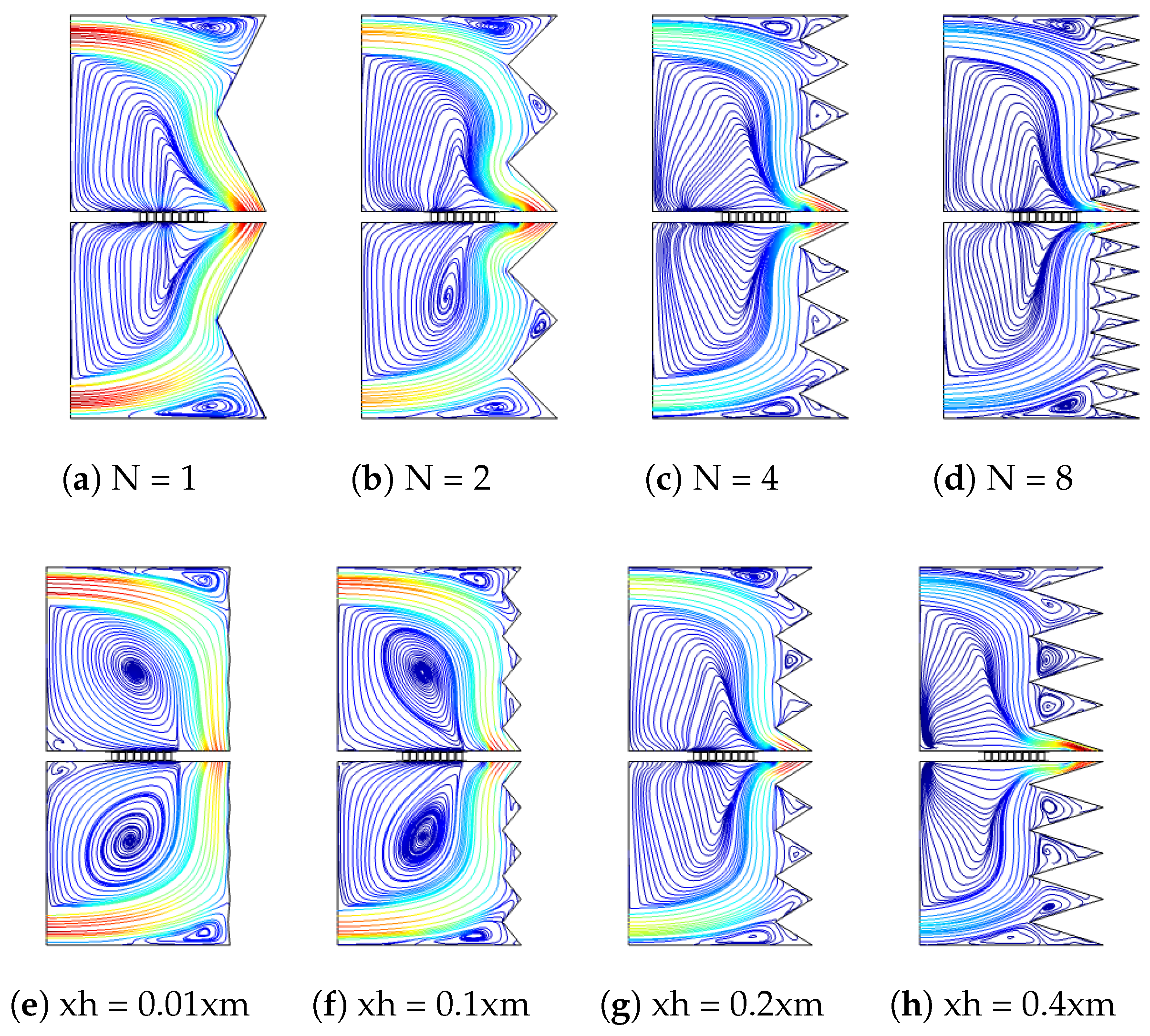
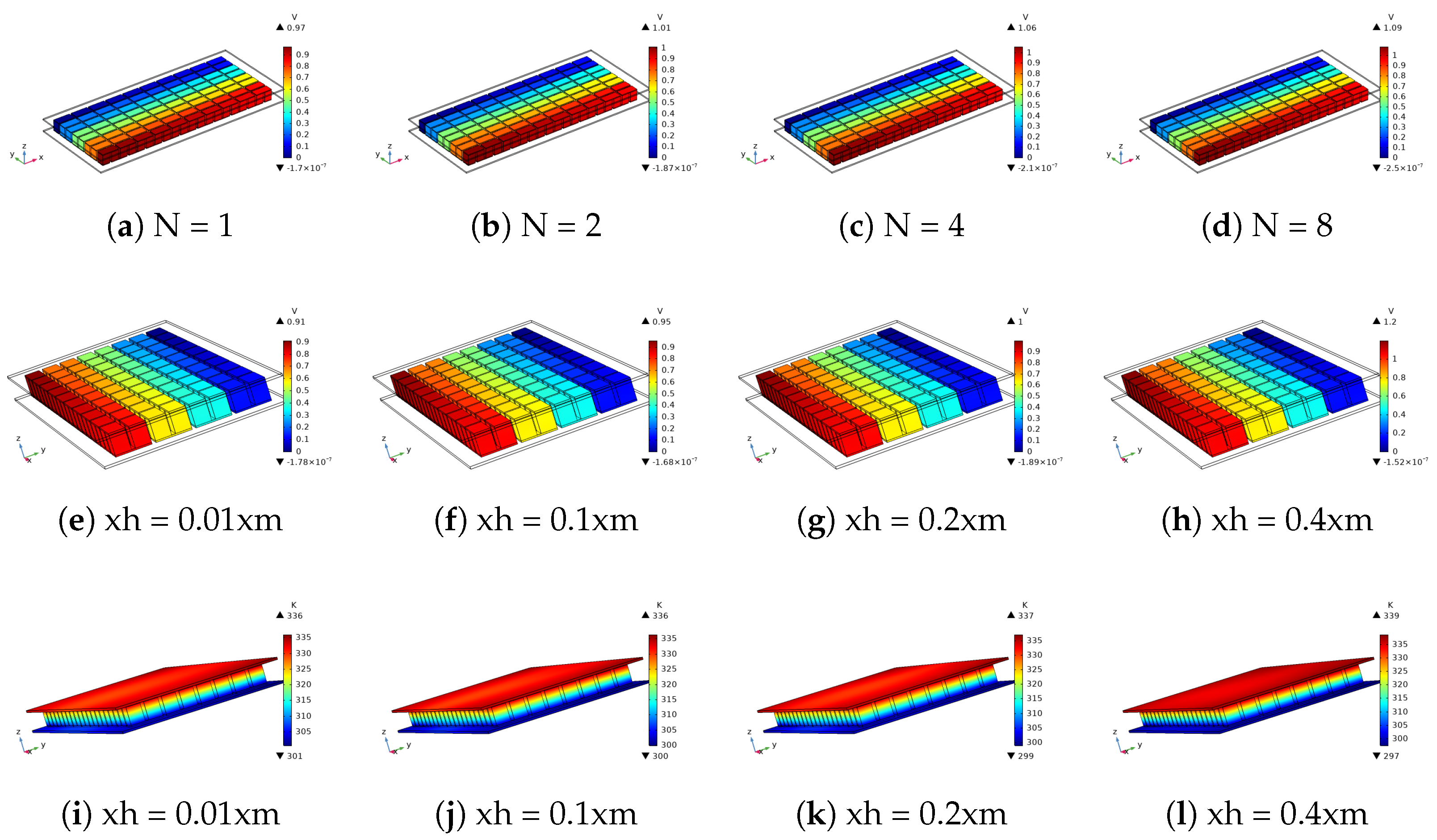
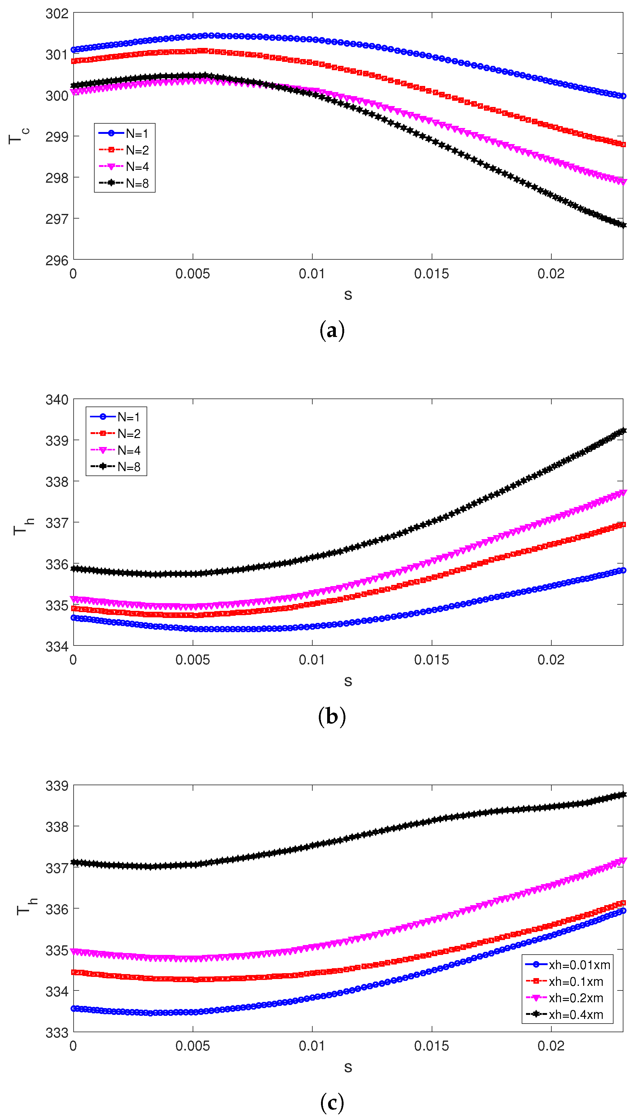
  • Impacts of wave amplitude on the flow field and conversion performance is significant as compared to the wave number of the VCs.
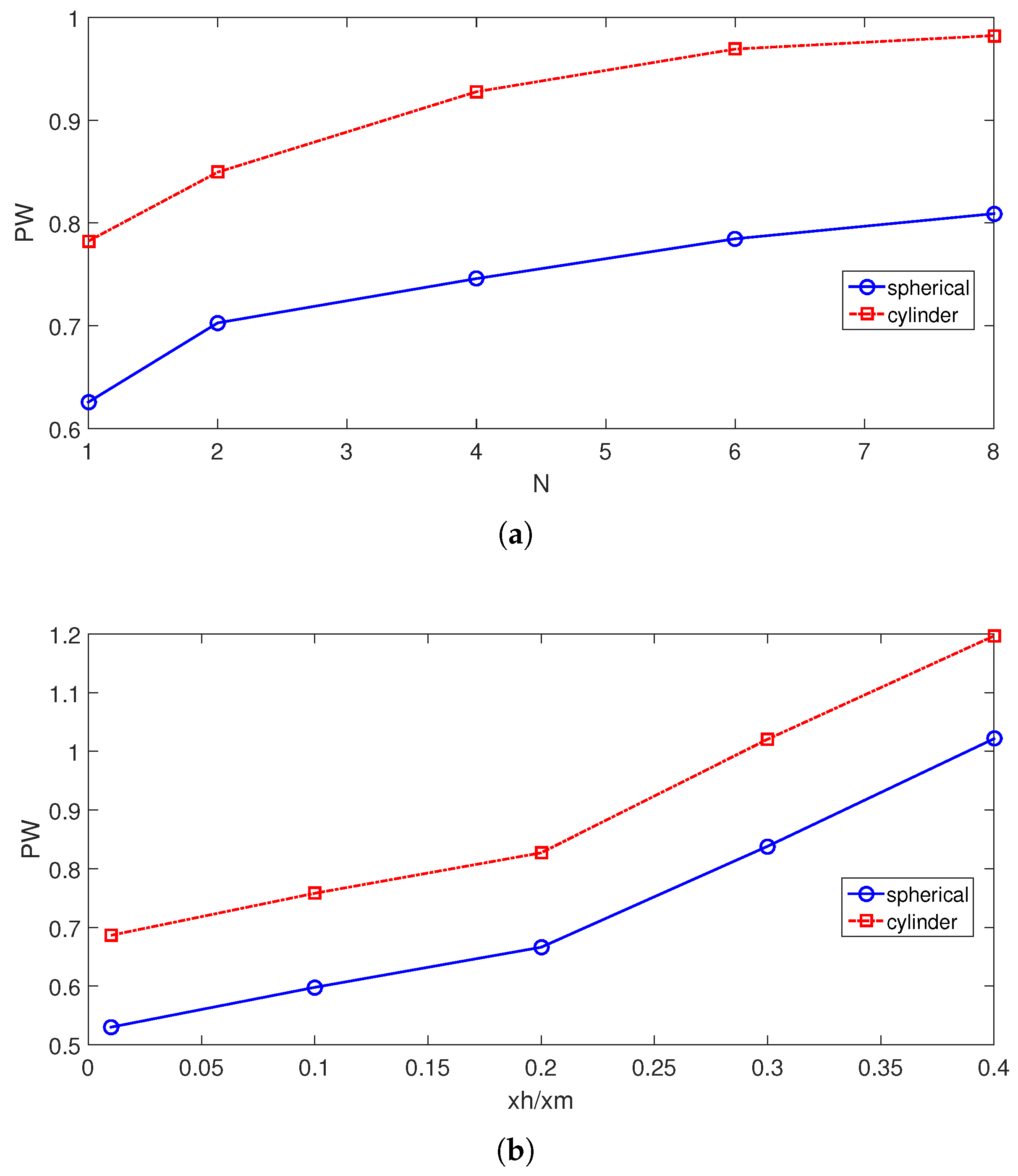
  • The rise of TEG power is in the range of 9.44–25.5% when varying the wave number, while it is in the range of 74.48–92.4% when varying the amplitude of the triangular wave.
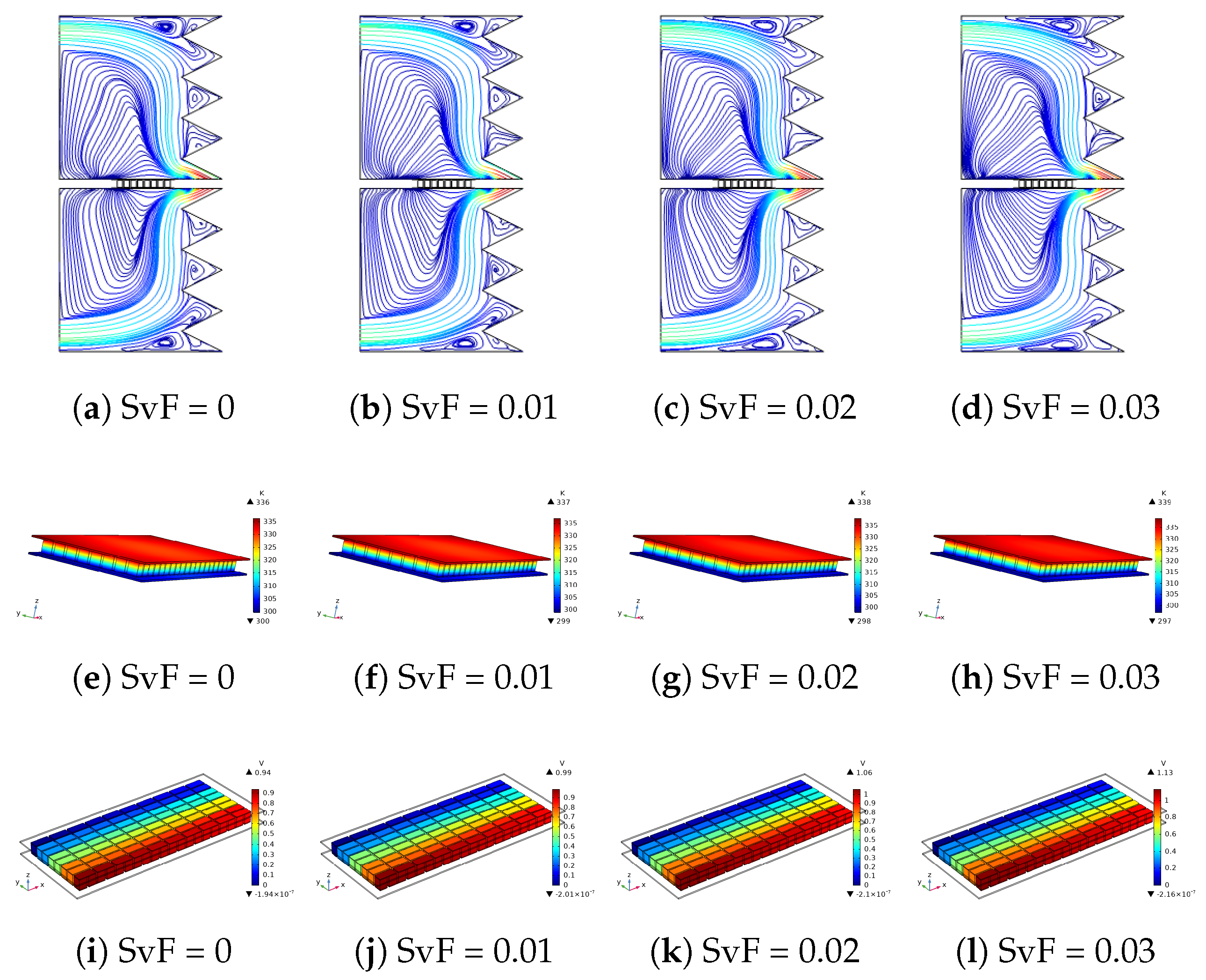
  • When NFs with the highest and lowest amount of NPs are compared, TEG power rises by about 50.7% for NF-cylinder while it is 4% for NF-spherical. Higher powers are obtained by using cylindrical NPs as compared to spherical ones in the HT fluid.
  • The results show that simultaneously using differently shaped NPs and the wavy form of the cavity has significant impacts on the overall performance improvements. As compared to the flat-walled VC case using only pure fluid, introducing a wavy form of the wall and including cylindrical NPs in the base fluid, up to a 194% rise of generated power is obtained.
As the extension of the work, different NFs, different forms of the wavy walls, flow pulsations and forms of the enclosure can be considered. Effects of the TEG geometry and material along with the form of the enclosure can also be taken into account. Pressure drop and entropy generation analysis may also be considered, since such modifications in the geometry of the cavity may result in lower second law efficiency. These will increase the applicability of the current results.

Author Contributions

Conceptualization, F.S.; methodology, F.S.; software, F.S.; validation, L.K.; formal analysis, F.S., W.A. and L.K.; investigation, F.S., L.K., W.A., M.O., H.B., N.B.K. and B.M.A.; writing—original draft preparation, F.S.; writing—review and editing, F.S., L.K., W.A., M.O., H.B., N.B.K. and B.M.A.; visualization, F.S. and L.K.; supervision, F.S., L.K., W.A., M.O., H.B., N.B.K. and B.M.A. All authors have read and agreed to the published version of the manuscript.

Funding

This research work was funded by Institutional Fund Projects under grant no. (IFPIP: 190-305-1443). Therefore, the authors gratefully acknowledge technical and financial support from the Ministry of Education and King Abdulaziz University, DSR, Jeddah, Saudi Arabia.

Institutional Review Board Statement

Not applicable.

Informed Consent Statement

Not applicable.

Data Availability Statement

Not applicable.

Conflicts of Interest

The authors declare no conflict of interest.

Abbreviations

hheat transfer coefficient
Hcavity height
kthermal conductivity
nunit normal vector
Nwave number
NuNusselt number
ppressure
PrPrandtl number
ReReynolds number
Ttemperature
u, v, wx-y-z velocity components
w i , w o inlet-outlet port size
x, y, zCartesian coordinates
x h wave amplitude
ZTfigure of merit
Greek Characters
α thermal diffusivity
μ dynamic viscosity
ν kinematic viscosity
ρ density of the fluid
σ electrical conductivity
ϕ solid volume fraction
Subscripts
ccold wall
hhot wall
maverage
nfnanofluid
Abbreviations
FEMfinite element method
VCvented cavity
TEGthermoelectric generator

References

  1. Patil, D.S.; Arakerimath, R.R.; Walke, P.V. Thermoelectric materials and heat exchangers for power generation—A review. Renew. Sustain. Energy Rev. 2018, 95, 1–22. [Google Scholar] [CrossRef]
  2. Karthick, K.; Suresh, S.; Hussain, M.M.M.D.; Ali, H.M.; Kumar, C.S.S. Evaluation of solar thermal system configurations for thermoelectric generator applications: A critical review. Sol. Energy 2019, 188, 111–142. [Google Scholar] [CrossRef]
  3. Champier, D. Thermoelectric generators: A review of applications. Energy Convers. Manag. 2017, 140, 167–181. [Google Scholar] [CrossRef]
  4. Gelbstein, Y. Pb1−x SnxTe alloys: Application considerations. J. Electron. Mater. 2011, 40, 533–536. [Google Scholar] [CrossRef]
  5. Gelbstein, Y.; Davidow, J.; Leshem, E.; Pinshow, O.; Moisa, S. Significant lattice thermal conductivity reduction following phase separation of the highly efficient GexPb1−xTe thermoelectric alloys. Phys. Status Solidi (b) 2014, 251, 1431–1437. [Google Scholar] [CrossRef]
  6. Ahmed, S.E. Caputo fractional convective flow in an inclined wavy vented cavity filled with a porous medium using Al2O3-Cu hybrid nanofluids. Int. Commun. Heat Mass Transf. 2020, 116, 104690. [Google Scholar] [CrossRef]
  7. Akdag, U.; Akcay, S.; Demiral, D. Heat transfer enhancement with laminar pulsating nanofluid flow in a wavy channel. Int. Commun. Heat Mass Transf. 2014, 59, 17–23. [Google Scholar] [CrossRef]
  8. Selimefendigil, F.; Oztop, H.F. Forced convection and thermal predictions of pulsating nanofluid flow over a backward facing step with a corrugated bottom wall. Int. J. Heat Mass Transf. 2017, 110, 231–247. [Google Scholar] [CrossRef]
  9. Shehzad, N.; Zeeshan, A.; Ellahi, R.; Vafai, K. Convective heat transfer of nanofluid in a wavy channel: Buongiorno’s mathematical model. J. Mol. Liq. 2016, 222, 446–455. [Google Scholar] [CrossRef]
  10. Wang, C.C.; Chen, C.K. Forced convection in a wavy-wall channel. Int. J. Heat Mass Transf. 2002, 45, 2587–2595. [Google Scholar] [CrossRef]
  11. Miroshnichenko, I.V.; Sheremet, M.A.; Pop, I.; Ishak, A. Convective heat transfer of micropolar fluid in a horizontal wavy channel under the local heating. Int. J. Mech. Sci. 2017, 128, 541–549. [Google Scholar] [CrossRef]
  12. Ahmed, M.; Shuaib, N.; Yusoff, M.Z. Numerical investigations on the heat transfer enhancement in a wavy channel using nanofluid. Int. J. Heat Mass Transf. 2012, 55, 5891–5898. [Google Scholar] [CrossRef]
  13. Selimefendigil, F.; Oztop, H.F. Corrugated conductive partition effects on MHD free convection of CNT-water nanofluid in a cavity. Int. J. Heat Mass Transf. 2019, 129, 265–277. [Google Scholar] [CrossRef]
  14. Pehlivan, H.; Taymaz, I.; İslamoğlu, Y. Experimental study of forced convective heat transfer in a different arranged corrugated channel. Int. Commun. Heat Mass Transf. 2013, 46, 106–111. [Google Scholar] [CrossRef]
  15. Tokgoz, N.; Tunay, T.; Sahin, B. Effect of corrugated channel phase shifts on flow structures and heat transfer rate. Exp. Therm. Fluid Sci. 2018, 99, 374–391. [Google Scholar] [CrossRef]
  16. Rashidi, S.; Akbarzadeh, M.; Masoodi, R.; Languri, E. Thermal-hydraulic and entropy generation analysis for turbulent flow inside a corrugated channel. Int. J. Heat Mass Transf. 2017, 109, 812–823. [Google Scholar] [CrossRef]
  17. Selimefendigil, F.; Öztop, H.F. Analysis of hybrid nanofluid and surface corrugation in the laminar convective flow through an encapsulated PCM filled vertical cylinder and POD-based modeling. Int. J. Heat Mass Transf. 2021, 178, 121623. [Google Scholar] [CrossRef]
  18. Kurtulmuş, N.; Sahin, B. A review of hydrodynamics and heat transfer through corrugated channels. Int. Commun. Heat Mass Transf. 2019, 108, 104307. [Google Scholar] [CrossRef]
  19. Saeidi, S.; Khodadadi, J. Forced convection in a square cavity with inlet and outlet ports. Int. J. Heat Mass Transf. 2006, 49, 1896–1906. [Google Scholar] [CrossRef]
  20. Angirasa, D. Mixed convection in a vented enclosure with an isothermal vertical surface. Fluid Dyn. Res. 2000, 26, 219–233. [Google Scholar] [CrossRef]
  21. Ismael, M.A.; Jasim, H.F. Role of the fluid-structure interaction in mixed convection in a vented cavity. Int. J. Mech. Sci. 2018, 135, 190–202. [Google Scholar] [CrossRef]
  22. Saeidi, S.; Khodadadi, J. Transient flow and heat transfer leading to periodic state in a cavity with inlet and outlet ports due to incoming flow oscillation. Int. J. Heat Mass Transf. 2007, 50, 530–538. [Google Scholar] [CrossRef]
  23. Selimefendigil, F.; Öztop, H.F. Numerical investigation and dynamical analysis of mixed convection in a vented cavity with pulsating flow. Comput. Fluids 2014, 91, 57–67. [Google Scholar] [CrossRef]
  24. Zahmatkesh, I.; Sheremet, M.; Yang, L.; Heris, S.Z.; Sharifpur, M.; Meyer, J.P.; Ghalambaz, M.; Wongwises, S.; Jing, D.; Mahian, O. Effect of nanoparticle shape on the performance of thermal systems utilizing nanofluids: A critical review. J. Mol. Liq. 2021, 321, 114430. [Google Scholar] [CrossRef]
  25. Sajid, M.U.; Ali, H.M. Recent advances in application of nanofluids in heat transfer devices: A critical review. Renew. Sustain. Energy Rev. 2019, 103, 556–592. [Google Scholar] [CrossRef]
  26. Mahian, O.; Kianifar, A.; Heris, S.Z.; Wen, D.; Sahin, A.Z.; Wongwises, S. Nanofluids effects on the evaporation rate in a solar still equipped with a heat exchanger. Nano Energy 2017, 36, 134–155. [Google Scholar] [CrossRef]
  27. Khanafer, K.; Vafai, K. A review on the applications of nanofluids in solar energy field. Renew. Energy 2018, 123, 398–406. [Google Scholar] [CrossRef]
  28. Arshad, W.; Ali, H.M. Graphene nanoplatelets nanofluids thermal and hydrodynamic performance on integral fin heat sink. Int. J. Heat Mass Transf. 2017, 107, 995–1001. [Google Scholar] [CrossRef]
  29. Mahbubul, I.; Khan, M.M.A.; Ibrahim, N.I.; Ali, H.M.; Al-Sulaiman, F.A.; Saidur, R. Carbon nanotube nanofluid in enhancing the efficiency of evacuated tube solar collector. Renew. Energy 2018, 121, 36–44. [Google Scholar] [CrossRef]
  30. Xiong, Q.; Bozorg, M.V.; Doranehgard, M.H.; Hong, K.; Lorenzini, G. A CFD investigation of the effect of non-Newtonian behavior of Cu-water nanofluids on their heat transfer and flow friction characteristics. J. Therm. Anal. Calorim. 2020, 139, 2601–2621. [Google Scholar] [CrossRef]
  31. Wang, L.; Huang, C.; Yang, X.; Chai, Z.; Shi, B. Effects of temperature-dependent properties on natural convection of power-law nanofluids in rectangular cavities with sinusoidal temperature distribution. Int. J. Heat Mass Transf. 2019, 128, 688–699. [Google Scholar] [CrossRef]
  32. Ellahi, R.; Hassan, M.; Zeeshan, A. A study of heat transfer in power law nanofluid. Therm. Sci. 2016, 20, 2015–2026. [Google Scholar] [CrossRef] [Green Version]
  33. Selimefendigil, F.; Chamkha, A.J. Magnetohydrodynamics mixed convection in a power law nanofluid-filled triangular cavity with an opening using Tiwari and Das’ nanofluid model. J. Therm. Anal. Calorim. 2019, 135, 419–436. [Google Scholar] [CrossRef]
  34. ul Haq, M.R.; Hussain, M.; Bibi, N.; Shigidi, I.M.; Pashameah, R.A.; Alzahrani, E.; El-Shorbagy, M.; Safaei, M.R. Energy transport analysis of the magnetized forced flow of power-law nanofluid over a horizontal wall. J. Magn. Magn. Mater. 2022, 560, 169681. [Google Scholar] [CrossRef]
  35. Qeays, I.A.; Yahya, S.M.; Asjad, M.; Khan, Z.A. Multi-performance optimization of nanofluid cooled hybrid photovoltaic thermal system using fuzzy integrated methodology. J. Clean. Prod. 2020, 256, 120451. [Google Scholar] [CrossRef]
  36. Karana, D.R.; Sahoo, R.R. Effect on TEG performance for waste heat recovery of automobiles using MgO and ZnO nanofluid coolants. Case Stud. Therm. Eng. 2018, 12, 358–364. [Google Scholar] [CrossRef]
  37. Selimefendigil, F.; Öztop, H.F. Performance assessment of a thermoelectric module by using rotating circular cylinders and nanofluids in the channel flow for renewable energy applications. J. Clean. Prod. 2021, 279, 123426. [Google Scholar] [CrossRef]
  38. Rajaee, F.; Rad, M.A.V.; Kasaeian, A.; Mahian, O.; Yan, W.M. Experimental analysis of a photovoltaic/thermoelectric generator using cobalt oxide nanofluid and phase change material heat sink. Energy Convers. Manag. 2020, 212, 112780. [Google Scholar] [CrossRef]
  39. Nnanna, A.G.A.; Rutherford, W.; Elomar, W.; Sankowski, B. Assessment of thermoelectric module with nanofluid heat exchanger. Appl. Therm. Eng. 2009, 29, 491–500. [Google Scholar] [CrossRef]
  40. Nazari, S.; Safarzadeh, H.; Bahiraei, M. Experimental and analytical investigations of productivity, energy and exergy efficiency of a single slope solar still enhanced with thermoelectric channel and nanofluid. Renew. Energy 2019, 135, 729–744. [Google Scholar] [CrossRef]
  41. Ahammed, N.; Asirvatham, L.G.; Wongwises, S. Thermoelectric cooling of electronic devices with nanofluid in a multiport minichannel heat exchanger. Exp. Therm. Fluid Sci. 2016, 74, 81–90. [Google Scholar] [CrossRef]
  42. Selimefendigil, F.; Öztop, H.F. Identification of pulsating flow effects with CNT nanoparticles on the performance enhancements of thermoelectric generator (TEG) module in renewable energy applications. Renew. Energy 2020, 162, 1076–1086. [Google Scholar] [CrossRef]
  43. Ferrouillat, S.; Bontemps, A.; Poncelet, O.; Soriano, O.; Gruss, J.A. Influence of nanoparticle shape factor on convective heat transfer and energetic performance of water-based SiO2 and ZnO nanofluids. Appl. Therm. Eng. 2013, 51, 839–851. [Google Scholar] [CrossRef]
  44. Liu, F.; Cai, Y.; Wang, L.; Zhao, J. Effects of nanoparticle shapes on laminar forced convective heat transfer in curved ducts using two-phase model. Int. J. Heat Mass Transf. 2018, 116, 292–305. [Google Scholar] [CrossRef]
  45. Benkhedda, M.; Boufendi, T.; Tayebi, T.; Chamkha, A.J. Convective heat transfer performance of hybrid nanofluid in a horizontal pipe considering nanoparticles shapes effect. J. Therm. Anal. Calorim. 2020, 140, 411–425. [Google Scholar] [CrossRef]
  46. Abderrahmane, A.; Hatami, M.; Medebber, M.; Haroun, S.; Ahmed, S.E.; Mohammed, S. Non-Newtonian nanofluid natural convective heat transfer in an inclined Half-annulus porous enclosure using FEM. Alex. Eng. J. 2022, 61, 5441–5453. [Google Scholar] [CrossRef]
  47. Kolsi, L.; Selimefendigil, F.; Said, L.B.; Mesloub, A.; Alresheedi, F. Forced Convection of Non-Newtonian Nanofluid Flow over a Backward Facing Step with Simultaneous Effects of Using Double Rotating Cylinders and Inclined Magnetic Field. Mathematics 2021, 9, 3002. [Google Scholar] [CrossRef]
  48. Alsabery, A.; Chamkha, A.; Saleh, H.; Hashim, I. Transient natural convective heat transfer in a trapezoidal cavity filled with non-Newtonian nanofluid with sinusoidal boundary conditions on both sidewalls. Powder Technol. 2017, 308, 214–234. [Google Scholar] [CrossRef]
  49. Selimefendigil, F.; Öztop, H.F.; Kolsi, L.; Omri, M. Performance analysis of thermoelectric generator mounted chaotic channel by using non-Newtonian nanofluid and modeling with efficient computational methods. Alex. Eng. J. 2022, 61, 3527–3549. [Google Scholar] [CrossRef]
  50. Khedher, N.B.; Selimefendigil, F.; Kolsi, L.; Aich, W.; Ben Said, L.; Boukholda, I. Performance Optimization of a Thermoelectric Device by Using a Shear Thinning Nanofluid and Rotating Cylinder in a Cavity with Ventilation Ports. Mathematics 2022, 10, 1075. [Google Scholar] [CrossRef]
  51. Kim, C.N. Development of a numerical method for the performance analysis of thermoelectric generators with thermal and electric contact resistance. Appl. Therm. Eng. 2018, 1305, 408–417. [Google Scholar] [CrossRef]
  52. Timofeeva, E.V.; Routbort, J.L.; Singh, D. Particle shape effects on thermophysical properties of alumina nanofluids. J. Appl. Phys. 2009, 106, 014304. [Google Scholar] [CrossRef]
  53. Vajjha, R.S.; Das, D.K. Experimental determination of thermal conductivity of three nanofluids and development of new correlations. Int. J. Heat Mass Transf. 2009, 52, 4675–4682. [Google Scholar] [CrossRef]
  54. Lewis, R.W.; Nithiarasu, P.; Seetharamu, K.N. Fundamentals of the Finite Element Method for Heat and Fluid Flow; John Wiley & Sons: West Sussex, UK, 2004. [Google Scholar]
  55. Heinrich, J.C.; Pepper, D.W. Intermediate Finite Element Method: Fluid Flow and Heat Transfer Applications; Routledge: New York, NY, USA, 2017. [Google Scholar]
  56. Reddy, J.N.; Gartling, D.K. The Finite Element Method in Heat Transfer and Fluid Dynamics; CRC Press: Boca Raton, FL, USA, 2010. [Google Scholar]
  57. Sourtiji, E.; Gorji-Bandpy, M.; Ganji, D.; Hosseinizadeh, S. Numerical analysis of mixed convection heat transfer of Al2O3-water nanofluid in a ventilated cavity considering different positions of the outlet port. Powder Technol. 2014, 262, 71–81. [Google Scholar] [CrossRef]
Figure 1. Schematic view of 3D model (a) and 2D model with boundary conditions (b).
Mathematics 11 00483 g001
Figure 2. Grid independence test (GIT) results: (a) PW variations with different grid sizes at two different SvF using cylindrical NPs (N = 4, xh = 0.3xm) and grid distributions (b).
Mathematics 11 00483 g002
Figure 3. Comparison of streamline distributions within the VC at Re = 500 available in the work of Ref. [57] (a) and obtained with the present code (b); average Nu versus Re comparisons (c).
Mathematics 11 00483 g003
Figure 4. Effects of wavy wall number (xh = 0.3xm) and amplitude of the wavy wall (N = 4) on the flow pattern variations with the VCs by using cylinder-shaped NPs in PF (SvF = 0.03).
Mathematics 11 00483 g004
Figure 5. Electric potential distribution for different wavy wall numbers ((ad), xh = 0.3xm), amplitude of the wavy wall ((eh), N = 4) and variations of temperature within the TEG for different wave amplitudes (il) by using cylindrical-shaped NPs in PF (SvF = 0.03).
Mathematics 11 00483 g005
Figure 6. Variation of IT between TEG and VC for different wavy wall numbers ((a,b), xh = 0.3xm) and amplitude of the wavy wall ((c), N = 4) by using cylindrical-shaped NPs in PF (SvF = 0.03).
Mathematics 11 00483 g006
Figure 7. Generated PW versus wavy wall numbers ((a), xh = 0.3xm) and amplitude of the wavy wall ((b), N = 4) by using cylindrical and spherical-shaped NPs in PF (SvF = 0.03).
Mathematics 11 00483 g007
Figure 8. Effects of NP loading amount in the base fluid on the streamline within VCs (ad), temperature of TEG (eh) and electric potential (il) distributions by using cylindrical-shaped NPs in PF (xh = 0.3xm, N = 4).
Mathematics 11 00483 g008
Figure 9. Impacts of two different NP loadings of different shapes on the hot side IT variations (a) and generated PW versus SvF of NPs in the base fluid with spherical and cylindrical-shaped NPs (b) (xh = 0.3xm, N = 4).
Mathematics 11 00483 g009
Figure 10. Hot side IT distributions by varying the NP loading amount in the base fluid by using spherical-shaped (a) and cylindrical-shaped (b) NPs in PF (xh = 0.3xm, N = 4).
Mathematics 11 00483 g010
Figure 11. Electric potential distributions for flat (a,b) and wavy (c,d) walled VC at two different NP loadings by using cylindrical shaped NPs (xh = 0.3xm, N = 4) and comparisons of different cases on the PW output of the TEG device (c).
Mathematics 11 00483 g011
Table 1. Material properties of the TEG module.
SymbolP Type Leg (Bi 2 Te 3 )N Type Leg (Bi 2 Te 3 )Electrode (Copper)Ceramic (Alumina)
Thermal conductivityk (W/m K)1.61.640027
Electric conductivity σ (S/m) 0.8 × 10 5 0.81 × 10 5 5.9 × 10 8 -
Seebeck coefficient α (V/K) 2.1 × 10 4 2.1 × 10 4 6.5 × 10 6 -
Heat capacityC p (J/kg K)154154385900
Density ρ (kg/m 3 )7700770089603900
Table 2. Thermophysical properties of water and alumina [31].
PropertySymbolWaterAl 2 O 3
Density (kg/m 3 ) ρ 9973970
Specific heat (J/kg K)c p 4179765
Viscosity (mPa.s) μ 0.895-
Thermal conductivity (W/m K)k0.61340
Table 3. Constant values for different shapes of Al 2 O 3 NPs [52].
ShapeC k A 1 A 2
Blade2.7414.6123.3
Cylinder3.9513.5904.4
Bricks3.371.9471.4
Disclaimer/Publisher’s Note: The statements, opinions and data contained in all publications are solely those of the individual author(s) and contributor(s) and not of MDPI and/or the editor(s). MDPI and/or the editor(s) disclaim responsibility for any injury to people or property resulting from any ideas, methods, instructions or products referred to in the content.

