Article

Analytical Solution of Stability Problem of Nanocomposite Cylindrical Shells under Combined Loadings in Thermal Environments

by
Mahmure Avey
1,2,3,
Nicholas Fantuzzi
4 and
Abdullah H. Sofiyev
5,6,7,*
1
Department of Mathematical Engineering, Graduate School of Istanbul Technical University, Maslak, 34469 Istanbul, Turkey
2
Analytical Information Resources Center of UNEC, Azerbaijan State Economics University, 1001 Baku, Azerbaijan
3
Application and Research Center, Istanbul Ticaret University, 34445 Istanbul, Turkey
4
Department of Civil, Chemical, Environmental, and Materials Engineering, University Bologna, 40136 Bologna, Italy
5
Department of Mathematics, Istanbul Ticaret University, Beyoglu, 34445 Istanbul, Turkey
6
Scientific Research Centers for Composition Materials of UNEC, Azerbaijan State Economic University, 100 Baku, Azerbaijan
7
Scientific Research Centers for Composite Constructions, Odlar Yurdu University, 1072 Baku, Azerbaijan
*
Author to whom correspondence should be addressed.
Mathematics 2023, 11(17), 3781; https://doi.org/10.3390/math11173781
Submission received: 18 July 2023 / Revised: 29 August 2023 / Accepted: 1 September 2023 / Published: 3 September 2023

Abstract

:
The mathematical modeling of the stability problem of nanocomposite cylindrical shells is one of the applications of partial differential equations (PDEs). In this study, the stability behavior of inhomogeneous nanocomposite cylindrical shells (INH-NCCSs), under combined axial compression and hydrostatic pressure in the thermal environment, is investigated by means of the first-order shear deformation theory (FSDT). The nanocomposite material is modeled as homogeneous and heterogeneous and is based on a carbon nanotube (CNT)-reinforced polymer with the linear variation of the mechanical properties throughout the thickness. In the heterogeneous case, the mechanical properties are modeled as the linear function of the thickness coordinate. The basic equations are derived as partial differential equations and solved in a closed form, using the Galerkin procedure, to determine the critical combined loads for the selected structure in thermal environments. To test the reliability of the proposed formulation, comparisons with the results obtained by finite element and numerical methods in the literature are accompanied by a systematic study aimed at testing the sensitivity of the design response to the loading parameters, CNT models, and thermal environment.
MSC:
74E10; 74E05; 74H55; 74K25; 74F05; 74G10

1. Introduction

Cylindrical shells play a key role in many high-tech fields, including aerospace, rocket and space technology, shipbuilding and automotive, nuclear reactors, and chemical engineering. Structural elements used in these areas should always renew themselves and new products of modern technology should be used. In this context, polymer-based nanocomposites (NCs) are increasingly attracting the attention of engineers and designers for stability and optimization problems. Structural elements formed from polymer-based nanocomposites have outstanding physical and chemical properties as well as superior mechanical properties such as lightness, corrosion resistance, and high specific strength.
The operating conditions in the application areas of cylindrical shells expose them to the simultaneous action of different loads such as compression forces and external pressures. Research attempts of buckling response for homogeneous composite cylindrical shells subjected to combined loading are relatively old. Some of the most important ones among these studies are references [1,2,3,4,5,6,7] and they contain many studies in their own period.
The formation of high-resolution microscopes led to the discovery of CNTs during the production of fullerenes by arc discharge evaporation in 1991 [8]. It is well known that carbon nanotubes, which have a cylindrical structure made of a graphene sheet, have outstanding mechanical properties such as high tensile strength and high elastic modulus. These properties are the reason why carbon nanotubes are considered as an ideal filling material for composites used in aerospace structural elements. Besides the outstanding electrical and thermal properties of CNTs, their mechanical properties have always attracted the attention of researchers and numerous studies have been carried out [9,10,11,12]. Sometime after CNTs were created, it became known that it was more advantageous to use them as a reinforcing element in addition to as a separate structural element. Developments in modern technology enabled the creation of polymer-, metal-, and ceramic-based CNTs-reinforced materials starting from 2005, and these materials began to take their place in the literature as nanocomposite materials [13,14,15,16,17]. Through a combination of many unique properties and exceptional design possibilities, polymer nanocomposites have proven themselves as high-performance materials of the twenty-first century and have the potential to be used in a wide variety of advanced technologies such as spacecrafts, rockets, submarines, automobiles, and others [18,19,20,21,22].
Due to their exceptional load-bearing capacity, nanocomposite cylindrical shells are used in various environments and are subjected to combined loads in operation. This makes it necessary to perform stability analyses of nanocomposite cylindrical shells subjected to combined loads during design.
After formulating the buckling problem of functionally graded nanocomposite cylindrical shells under separate external pressures in thermal environments in Shen’s study [23,24], the buckling problem of nanocomposite cylindrical shells under combined loads was investigated by Shen and Xiang [25] using boundary layer theory and a singular perturbation procedure. In the literature, in most studies devoted to solving the problem of buckling of nanocomposite circular shells, separate action loads were considered, and the number of studies is limited due to the difficulties of mathematically modeling the combined loads and solving their problems [26,27,28,29,30,31,32,33,34,35,36,37,38,39,40,41,42,43,44].
As can be seen from the literature review, the modeling of buckling behavior of structural elements, consisting of traditional and new generation homogeneous and inhomogeneous composites in thermal environments, is generally in the form of PDEs, and analytical solutions are limited in comparison to numerical solutions. However, analytical solutions can help to formulate problems in numerical simulations correctly and to check results, as they provide a better understanding of the subject qualitatively. One of the most dangerous and unpredictable buckling problems of inhomogeneous nanocomposite cylindrical shells subjected to various static loads is under combined loads and their solution poses serious challenges due to the extreme operating conditions of modern structural members and the high safety and reliability demands placed on them. Besides the inhomogeneous nature of nanocomposites, another challenge is the mathematical modeling of the thermal environment effect and the incorporation of cylindrical shells under the combined loads into the stability equations. All these difficulties complicate the formulation of the problem, the formation of basic relationships, the modeling of governing equations in the framework of advanced theories, and the analytical solution. These difficulties, which require interdisciplinary knowledge, are among the reasons why the buckling behavior of cylindrical shells made of inhomogeneous nanocomposites and subjected to combined loads in thermal environments has not been sufficiently investigated in the framework of FSDT until now. The aim of this study is to deal with the subject in detail. A systematic study is being conducted to evaluate the sensitivity of the buckling response of nanocomposite cylindrical shells under combined loads within FSDT on the geometry, distribution, and volume fraction of CNTs used as reinforcement, which may be of great interest for design purposes. In addition, the results obtained in the framework of FSDT were interpreted in comparison with the results obtained in the framework of the Kirchhoff–Love theory (KLT), and the importance of transverse shear strain influences with and without thermal environments is revealed.
The structure of the article is as follows: In Section 2, the mathematical modeling of the mechanical properties of nanocomposites in thermal environments is presented and the basic equations are derived, in Section 3 the solution method is presented, the parametric analysis is included in Section 4, and conclusions are discussed in Section 5.

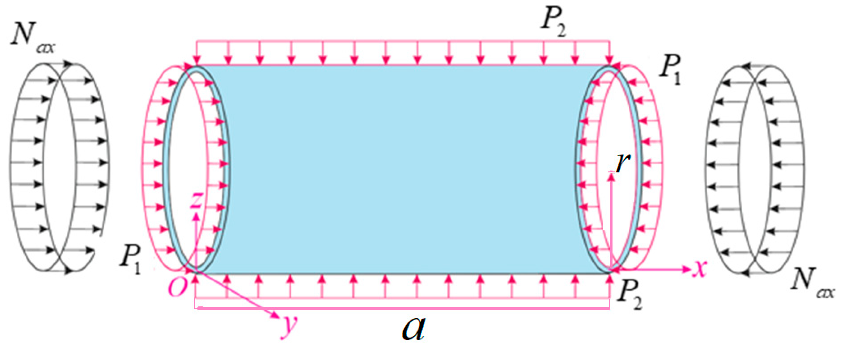
2. Mathematical Modeling of the Problem

2.1. Basic Relationships

The notes on the inhomogeneous nanocomposite cylindrical shell and its geometry, subjected to the combined effect of axial compressive load and hydrostatic pressure, are drawn in Figure 1. Geometric parameters such as the length, radius, and thickness of the INH-NCCSs are denoted by a ,     r , and t , respectively. Suppose the displacements in the x , y , and z directions are u ,   v , and w , respectively. ψ 1 and ψ 2 refer to the rotations of the mid-surface normal about the y and x axes, respectively. Let Ψ be the Airy stress function with the forces N i j ( i , j = 1 , 2 ) defined by [1,2]
N 11 ,     N 22 ,   N 12 = t 2 y 2 ,   2 x 2 ,   2 x y Ψ .
The inhomogeneous nanocomposite cylindrical shell subjected to the compressive axial load and external pressures [1,45,46]:
N 110 = N a x 0.5 P 1 r ,         N 220 = P 2 r ,           N 120 = 0 .
where N i j 0 ( i , j = 1 , 2 ) are the membrane forces for the condition with zero initial moments, N a x is the axial compressive load, and P j ( j = 1 , 2 ) indicate the uniform external pressures. If the external pressures in Figure 1 consider only the lateral pressure, it is N a x = 0 , P 1 = 0 and P 2 = P L , whereas for the hydrostatic pressure, it is assumed that N a x = 0 and P 1 = P 2 = P H .
Since the material properties of the CNT and matrix are temperature-dependent, the effective mechanical properties and thermal expansion coefficients of the nanocomposite will be functions of temperature and location. The effective Poisson ratio and density of the nanocomposite are considered constant since they are weakly dependent on the temperature change and location. These assumptions allow the expression of the micromechanical model of the effective mechanical and thermal properties of INH-NCCSs as follows [23,24]:
Y 11 ( Z , T ) = e 1 V C N Y 11 T C N + V m Y T m ,         e 2 Y 22 ( Z , T ) = V C N Y 22 T C N + V m Y T m ,     e 3 G 12 ( Z , T ) = V C N G 12 T C N + V m G T m ,     G 13 ( Z , T ) = G 12 ( Z , T ) ,       G 23 ( Z , T ) = 1.2 G 12 ( Z , T ) ,     ν 12 = V * C N ν 12 C N + V m ν m ,     ρ = V * C N ρ C N + V m ρ m .
and
α 11 ( Z , T ) = V C N Y 11 T C N α 11 T C N + V m Y T m α T m V C N Y 11 T C N + V m Y T m   ,     α 22 ( Z , T ) = ( 1 + ν 12 C N ) V C N α 22 T C N + ( 1 + ν m ) V m α T m ν 12 α 11 ( Z , T ) .
in which V * C N is the total volume fraction that depends on the density ρ C N , and the mass   m C N of CNTs and density ρ m of the matrix are defined by
V * C N = ρ C N m C N ρ m ρ C N ρ m + 1 1 .
The symbols used in Equations (3) and (4) are described as Y i i T ( Z , T ) , G i j T ( Z , T ) ( i = 1 , 2 , j = 1 , 2 , 3 ) and refer to the normal and shear elastic moduli of NCs that depend on the nondimensional thickness coordinate and temperature ( Z , T ) ; ν 12 refers to the Poisson’s ratio of NCs; ρ refers to the density of NCs; V C N and V m refer to the volume fraction of CNTs and polymer, respectively; ν 12 C N and ν m refer to the volume fraction of CNTs and polymer; Y i i T C N , G i j T C N , and Y T m , G T m refer to the normal and shear elastic moduli for CNTs and polymer; and e j ( j = 1 , 2 , 3 ) refer to the efficiency parameters for CNTs and V C N + V m = 1 . Here, α 11 T C N ,     α 22 T C N , and α T m refer to thermal expansion coefficients of CNTs and polymer, respectively. It also shows that Young’s modules and thermal expansion coefficients with their upper index ( Z , T ) depend on the thickness coordinate and temperature, indicating that the parameters with sub index T are dependent only on temperature.
Except for the uniform (U) distribution of the CNT distribution in the NCs in the thickness direction, three types of models are considered, namely the Λ-, X-, and V-models, and these can be estimated using the following relation [23,24]:
V C N = V * C N for   U , 1 + 2 Z V * C N for   Λ , 4 Z V * C N for   X , 1 2 Z V * C N for   V .
The shapes of uniform and inhomogeneous distributions of CNTs in the thickness direction of the polymer matrix, defined by the relation (2), are plotted in Figure 2.

2.2. Basic Equations

In the framework of FSDT, the constitutive relations for INH-NCCSs in the thermal environments can be created as follows [23]:
σ x x σ y y σ x y = Y ¯ 11 ( Z , T )           Y ¯ 12 ( Z , T )           0 Y ¯ 21 ( Z , T )           Y ¯ 22 ( Z , T )           0       0                       0                       Y ¯ 66 ( Z , T ) ε x x ε y y γ x y + σ x x T σ y y T 0 .
and
σ x z σ y z = Y ¯ 55 ( Z , T )           0             0                   Y ¯ 44 ( Z , T ) γ x z γ y z .
where
σ x x T = Y ¯ 11 ( Z , T ) α 11 ( Z , T ) + Y ¯ 12 ( Z , T ) α 22 ( Z , T ) Δ T   ,     σ y y T = Y ¯ 21 ( Z , T ) α 11 ( Z , T ) + Y ¯ 22 ( Z , T ) α 22 ( Z , T ) Δ T   .
in which σ i j ( i , j = x , y , z ) , ε j j ( j = x , y ) , and γ i j ( i , j = x , y , z ) are the stress and strain tensors of INH-NCCSs, respectively; Δ T = T T 0 is the symbol indicating the temperature rise from some reference temperature ( T 0 ) , in which thermal strains are also absent; and the material constants, T is the temperature and Y ¯ i j ( Z , T ) ,     ( i , j = 1 , 2 , 6 ) are defined as follows:
Y ¯ 11 ( Z , T ) = Y 11 ( Z , T ) 1 ν 12 ν 21 ,     Y ¯ 22 ( Z , T ) = Y 22 ( Z , T ) 1 ν 12 ν 21 ,     Y ¯ 12 ( Z , T ) = ν 21 Y 11 ( Z , T ) 1 ν 12 ν 21 = ν 12 Y 22 ( Z , T ) 1 ν 12 ν 21 = Y ¯ 21 ( Z , T ) ,   Y ¯ 44 ( Z , T ) = G 23 ( Z , T ) ,     Y ¯ 55 ( Z , T ) = G 13 ( Z , T ) ,     Y ¯ 66 ( Z , T ) = G 12 ( Z , T ) .
According to the assumptions of FSDT of the Ambartsumian [44], the variation of shear stress along the thickness direction can be written as follows:
σ z z = 0 ,         σ x z = d f d z ψ 1 ( x , y ) ,       σ y z = d f d z ψ 2 ( x , y ) .
where f refers to the shear stress shape function.
By combining Equations (6), (7), and (10), one obtains the following:
ε x x ε y y γ x y = e x x z 2 w x 2 + F 1 ( Z , T ) ψ 1 x e y y z 2 w y 2 + F 2 ( Z , T ) ψ 2 y γ 0 x y 2 z 2 w x y + F 1 ( Z , T ) ψ 1 y + F 2 ( Z , T ) ψ 2 x .
where e x x ,   e y y ,     γ 0 x y refer to the strain components at the mid-surface. F 1 ( Z , T ) and F 2 ( Z , T ) are defined as
F 1 ( z , T ) = 0 z 1 Y ¯ 55 ( Z , T ) d f d z d z ,               F 2 ( z , T ) = 0 z 1 Y ¯ 44 ( Z , T ) d f d z d z .
By integrating the stresses across the shell thickness, we can obtain stress resultants as follows [1]:
N i j , Q i ,   M i j = 0.5 t 0.5 t σ i j , σ i z ,     z σ i j d z ,     ( i , j = x , y ) .
Thermal forces and moments ( N i i T , M i i T ,     i = 1 , 2 ) caused by high temperature are found from the following integrals [23,24,25]:
( N 11 T , M 11 T ) = 0.5 t 0.5 t Y ¯ 11 ( Z , T ) α 11 ( Z , T ) + Y ¯ 12 ( Z , T ) α 22 ( Z , T ) Δ T 1 , z d z ,   ( N 22 T ,     M 22 T ) = 0.5 t 0.5 t Y ¯ 21 ( Z , T ) α 11 ( Z , T ) + Y ¯ 22 ( Z , T ) α 22 ( Z , T ) Δ T 1 , z d z .
Using Equations (7)–(9), (12), and (14) together, the stability and compatibility equations for INH-NCCSs under combined load can be expressed with four independent parameters, Ψ ,     w ,     ψ 1 ,   ψ 2 , as follows:
L 11       L 12         L 13       L 14 L 21       L 22         L 23       L 24 L 31       L 32         L 33       L 34 L 41       L 42         L 43       L 44 Ψ w ψ 1 ψ 2 = 0 0 0 0 .
where L i j are differential operators, whose details are described in Appendix A.

3. Solution Procedure

The two end edges of the cylindrical shell are simply supported, and these boundary conditions are, mathematically, as follows [23,45,46]:
At x = 0 ,   L         w = 2 Ψ y 2 = ψ 2 = M 11 = 0 .
0 2 π r N 11 d y + 2 π r t σ x + π r 2 p = 0 .
where σ x is the average axial compressive stress and the closed or periodicity condition is expressed as
0 2 π r v y d y = 0 .
The approximation functions are searched as follows [33,47]:
Ψ = K 1 sin ( μ 1 x )   sin ( μ 2 y ) ,       w = K 2 sin ( μ 1 x )   sin ( μ 2 y ) ,     ψ 1 = K 3   cos ( μ 1 x )   sin ( μ 2 y ) ,     ψ 2 = K 4   sin ( μ 1 x )   cos ( μ 2 y ) .
where K i refer to unknown amplitudes, μ 1 = m π a and μ 2 = n r , and where m and n are the longitudinal and circumferential wave numbers, respectively, contained in these parameters.
By introducing (20) into Equation (16), and also taking into account (2), then using the Galerkin procedure we obtain the following:
Q 11       Q 12           Q 13       Q 14 Q 21       Q 22         Q 23       Q 24 Q 31       Q 32         Q 33       Q 34 Q 41             Q 42           Q 43       Q 44 K 1 K 2 K 3 K 4 = 0 0 0 0 .
The Q i j contained in the square matrix of (21) refer to the coefficients characterizing the INH-NCCSs properties in the thermal environments and the combined load components and these are defined in Appendix B.
When the expansion of the determinant of the square matrix of Equation (21), with respect to the fourth row and the first column, is set to zero, the following equation is obtained, which provides the analytical expressions determining the critical axial load and critical external pressures of the INH-NCCSs in the thermal environments:
Q 41 Λ 1   N a x μ 1 2 + 0.5 P 1 μ 1 2 r + P 2 μ 2 2 r   Λ 2 + Q 43 Λ 3 + Q 44 Λ 4 = 0 .
where cofactors Λ i are expressed as
Λ 1 = Q 12     Q 13     Q 14 Q 22   Q 23     Q 24 Q 32     Q 33     Q 34 ,     Λ 2 = Q 11     Q 13     Q 14 Q 21     Q 23     Q 24 Q 31     Q 33     Q 34 ,     Λ 3 = Q 11     Q 12     Q 14 Q 21     Q 22     Q 24 Q 31     Q 32       Q 34 ,       Λ 4 = Q 11     Q 12     Q 13 Q 21     Q 22     Q 23 Q 31     Q 32     Q 33 .
From Equation (22) for INH-NCCSs, we obtain the following expressions for the nondimensional critical axial load ( N ¯ f s d t a x c r ), as P 1 = P 2 = 0 , for the nondimensional critical lateral pressure ( P ¯ f s d t L c r ), as N a x = P 1 = 0 ; P 2 = P L and for the nondimensional critical hydrostatic pressure ( P ¯ f s d t H c r ), as N a x = 0 ,   P 1 = P 2 = P H , respectively, in the thermal environments:
N ¯ f s d t a x c r = Φ t μ 1 2 Y m ,           P ¯ f s d t L c r = Φ Y m μ 2 2 r ,           P ¯ f s d t H c r = Φ Y m 0.5 μ 1 2 + μ 2 2 r .
where Φ = Q 41 Λ 1 +   Q 43 Λ 3 + Q 44 Λ 4 Λ 2 and Y m is the modulus of elasticity of the polymer at T 0 = 300   ( K ) (at room temperature).
For the combined axial load and lateral pressure, or combined axial load and hydrostatic pressure acting on the INH-NCCSs within FSDT in the thermal environments, the following relation can be used [1,32,46]:
N ¯ N ¯ f s d t a x c r + P ¯ L P ¯ f s d t L c r = 1         and         N ¯ N ¯ f s d t a x c r + P ¯ H P ¯ f s d t H c r = 1 .
where
N ¯ = N a x Y m t ,       P ¯ L = P L Y m ,     P ¯ H = P H Y m .
Under the assumptions N ¯ = δ P ¯ L and N ¯ = δ P ¯ H , in Equation (25), one obtains the following:
P ¯ f s d t L c b c r = 1 P ¯ f s d t L c r + δ N ¯ f s d t a x c r 1     and         P ¯ f s d t H c b c r = 1 P ¯ f s d t H c r + δ N ¯ f s d t a x c r 1   .
where δ 0 is the nondimensional load-proportional parameter.
From Equations (24) and (27), the values of critical combined loads within classical shell theory, P ¯ k l t L c b c r and P ¯ k l t H c b c r , in the thermal environment, can be found as the influence of transverse shear strains is neglected.

4. Results and Discussion

4.1. Initial Data

The comparison and specific numerical results for nanocomposite cylindrical shells subjected to two kinds of combined loads are performed in this section. The effective material properties of the nanocomposite are defined as follows: PMMA, with the abbreviated name of poly (methyl methacrylate), whose material properties are ν m = 0.34 ,     α T m = 45 ( 1 + 0.0005 Δ T ) × 10 6 / K and Y T m = ( 3.52 0.0034 T ) × 10 9   ( Pa ) . Here, T = T 0 + Δ T in which T 0 = 300   ( K ) . At reference temperature, that is, at T 0 = 300   K , α T m = α m = 45 × 10 6 / K ,         Y T m = Y m = 2.5 × 10 9   Pa .
Single-walled carbon nanotubes (SWCNTs), namely (10, 10) SWCNTs, with properties a C N = 9.26   nm ,     r C N = 0.68   nm ,     t C N = 0.067   nm ,             ν 12 C N = 0.175 , are used as reinforcement. The temperature-dependent material properties of (10, 10) SWCNTs are evaluated as [48]
Y 11 T C N = 6.18387 2.86 × 10 3 T + 4.22867 × 10 6 T 2 2.2724 × 10 9 T 3 , Y 22 T C N = 7.75348 3.58 × 10 3 T + 5.30057 × 10 6 T 2 2.84868 × 10 9 T 3 , G 12 T C N = 1.80126 + 0.77845 × 10 3 T 1.1279 × 10 6 T 2 + 4.93484 × 10 10 T 3 , α 11 T C N = ( 1.12148 + 2.289 × 10 2 T 2.88155 × 10 5 T 2 + 1.13253 × 10 8 T 3 ) 10 6 / K , α 22 T C N = ( 5.43874 9.95498 × 10 4 T + 3.13525 × 10 7 T 2 3.56332 × 10 12 T 3 ) 10 6 / K .
The magnitudes of material properties and thermal expansion coefficients for T = 300, 450, 600, and 750 (K) of (10, 10) SWCNTs using the above equations are presented in Table 1.
As is known, there are no experiments to determine the values of the efficiency parameters of nanocomposites. For the current analysis, the CNT efficiency parameters e i ( i = 1 , 2 , 3 ) represent the Young moduli ( Y 11 ,   Y 22 ) and shear modulus ( G 12 ) determined from the extended mixing rule of nanocomposites, as obtained from molecular dynamics simulations by Griebel and Hamaekers [49], and Han and Elliott [50], and determined by matching with similar values. The typical values of CNT efficiency parameters are listed in Table 2.
The shear stress shape functions are distributed as d f d z = 1 4 Z 2   [47]. The critical combined load values of INH-NCCSs in the thermal environments are calculated for different shell characteristics within the KLT and FSDT.

4.2. Comparative Examples

Before the parametric analyses, the values of the critical axial/hydrostatic combined load of the X-model INH-NCCSs within FSDT for two different load-proportional parameters are compared with the results of Shen and Xiang [25] for T = 300 (K). In the comparison, the following geometric data are considered: t = 0.002   m ,     r = 0.06   m , and a = 10 3 r t , which are taken from the study of Shen and Xiang [25] that used higher order shear deformation theory. The values corresponding to T = 300 (K) in Table 1 are used as the material properties. According to Table 3, good agreement can be observed between Shen and Xiang’s [25] estimates for the critical combined load and our results.
The numerical results of the critical lateral pressure, P f s d t L c r (in kPa), for the CNT-reinforced PMMA-based cylindrical shell of various lengths are compared with the results estimated by the finite element method of Hajoui et al. [26] and the two-stage singular perturbation technique of Shen [24] based on the higher order shear deformation theory. Other data used in the comparison are: r / t = 30 ,   h = 2   mm ,   V * C N = 0.17 and T = 300 (K). Two CNT pattern types are considered, U and X, and the numbers in parentheses indicate the circumferential mode numbers. Despite the difference in the solution methods, it is seen in Table 4 that the existing solutions are in good agreement with the results obtained using the numerical method [24] and finite element method [26]. It should be noted that the number of circumferential modes matches exactly those obtained in the comparative studies.

4.3. Parametric Analyses

In what follows, we analyze the sensitivity of the critical combined load to inhomogeneous models, the volume fractions of CNT and FSDT formulation, and the change in temperature, by considering the ratios 100 % × P ¯ I N H H c b c r P ¯ U H c b c r P ¯ U H c b c r ,     P ¯ k l t H c b c r P ¯ f s d t H c b c r P ¯ k l t H c b c r ,     P ¯ T H c b c r P ¯ T 0 H c b c r P ¯ T 0 H c b c r . Two of the main parameters affecting the critical combined loads are the load proportional parameter and the temperature variation. Since the number of longitudinal waves is equal to one, it is not included in the tables and figures. The buckling modes corresponding to the critical combined load values in Figure 3, Figure 4, Figure 5, Figure 6, Figure 7 and Figure 8 are presented in Table 5 and Table 6, as well as given in parentheses within the figures. The symbol T0 corresponds to the value T = 300 (K).
The distribution of the nondimensional critical combined loads and the corresponding circumferential wave numbers ( n c r ) of four types of polymer-based and CNT-patterned cylindrical shells in thermal environments versus the nondimensional load-proportional parameter ( δ ) within two theories are shown in Table 5 and Figure 3, Figure 4, Figure 5 and Figure 6. The data used in numerical calculations are considered as: r / t = 25 ,   a / r = 1 ,   t = 0.002   m , V * C N = 0.12 . The magnitudes of the nondimensional critical combined load and the corresponding circumferential wave numbers of four types of CNT-patterned cylindrical shells in thermal environments within two theories reduce as the δ rises. The effect of shear deformations (SDs) on the critical combined load differs with the change in temperature. At T = 300 (K), when the δ increases from 100 to 500, the influence of SDs on P ¯ f s d t H c b c r values rises for the U-model, while that influence becomes weaker as the δ rises up to 900. When the δ load-proportional parameter rises from 100 to 500, the effect of transverse SDs on the P ¯ f s d t H c b c r diminishes for the V-model, while that influence changes irregularly with the rise in the δ up to 900. As the δ load-proportional parameter increases from 100 to 500, the influence of SDs on the P ¯ f s d t H c b c r values diminishes in the Λ-model, while that influence reduces weakly but continuously as the δ increases up to 900. The effect of transverse SDs on the magnitudes of the P ¯ f s d t H c b c r decreases continuously when it increases from 100 to 900 for the X-model.
At T = 450 (K), as the load-proportional parameter increases from 100 to 300, the effect of transverse SDs on the P ¯ f s d t H c b c r increases for U-, V-, and Λ-models, while that effect weakens and reduces continuously as δ increases up to 900. When the δ increases from 100 to 500, the influence of transverse SDs on the P ¯ f s d t H c b c r rises as δ increases from 100 to 300, while that effect changes irregularly as the δ increases up to 900 for the X-model.
At T = 600 (K), when the δ load-proportional parameter increases from 100 to 300, the influence of SDs on the magnitudes of the P ¯ f s d t H c b c r increases in the U-model, while that influences reduces as the δ increases up to 900. When the δ increases from 100 to 500, the influence of transverse SDs on the P ¯ f s d t H c b c r increases for the V- and X-models, while that effect changes irregularly as the δ increases up to 900. When the δ increases from 100 to 500, the effect of SDs on the P ¯ f s d t H c b c r values rises in the Λ -model, while that effect decreases as δ increases up to 900.
At T = 750 (K), as the δ increases from 100 to 500, the effect of transverse SDs on the P ¯ f s d t H c b c r increases in the U-model, while that effect decreases as the δ load ratio increases up to 900. As the δ increases from 100 to 500, the effect of transverse SDs on P ¯ f s d t H c b c r increases for the V-model, while that effect decreases as δ increment up to 900. When the δ increases from 100 to 300, the effect of SDs on P ¯ f s d t H c b c r rises for the Λ -model, while that influence decreases continuously as the δ increases up to 900. For the X-model, the effect of transverse SDs on P ¯ f s d t H c b c r rises continuously when it increases from 100 to 500, while that effect changes irregularly when δ increases up to 900.
Although the increase in temperature changes according to the shape of inhomogeneous models on the P ¯ f s d t H c b c r , that rises the influence of inhomogeneity on the values of the critical combined load in all models. For example, at T = 300 (K), as the δ increases from 100 to 900, the influence of the V-, Λ-, and X-models on the P ¯ f s d t H c b c r rises from (−11.21%) to (−13.95%), (−17.83%) to (−19.77%), and (+21.62%) to (+23.98%), respectively, while at T = 750 (K), those effects increase from (−13.08%) to (−16.32%), (−16.72%) to (−19.58%), and (+18.54%) to (+21.45%), respectively, considering the transverse shear deformations significantly reduces the effects of the models (Figure 3 and Figure 4).
When comparing the influence of temperature on the P ¯ f s d t H c b c r at T = 450 (K) and T = 300 (K), if the δ rises from 100 to 900, the influence of temperature on the P ¯ f s d t H c b c r shows a decrease varying between 1% and 1.7%, according to the shape of patterns. When T = 600 (K) and T0 = 300 (K) are compared, if the δ increases from 100 to 900, the temperature effect on the P ¯ f s d t H c b c r shows a decrease of approximately 2.4% to 3.0%, depending on the shape of models. When T = 750 (K) and T = 300 (K) are compared, if the δ increases from 100 to 900, the temperature effect on the P ¯ f s d t H c b c r values shows the decrease between approximately 3.3% and 4.3%, depending on the shape of the models. The most significant effect of temperature occurs when δ = 100 and T = 300 (K) in the X-model with (−43.58%). A consideration of the transverse SDs significantly increases the effect of temperature on the P ¯ f s d t H c b c r . In some cases, the difference in effect of the temperature on the P ¯ f s d t H c b c r within the framework of the two theories is up to 13% (Figure 5 and Figure 6).
The distribution of P ¯ f s d t H c b c r , P ¯ k l t H c b c r , and corresponding circumferential wave numbers of polymer-based cylindrical shells reinforced with the CNT in the thermal environment versus the a / r , are shown in Table 6 and Figure 7 and Figure 8. The data used in the numerical calculations are considered as: r / t = 25 ,   t = 0.002   m ,   V * C N = 0.12 ,     δ = 500 . Increasing the a / r ratio significantly reduces the values of the critical combined loads based on the KLT and FSDT, and corresponding wave numbers decrease slightly. At a small a / r , the influence of transverse SDs on the critical combined load is quite large and is more likely to damage the structure.
The increase in the a / r significantly reduces the effect of transverse shear deformations on the critical combined load at the fixed value of the r / t (=25). Although the effects of SDs on the P ¯ f s d t H c b c r in different models decrease when the a / r rises, the model types maintain their sensitivity. The most significant effect on the P ¯ f s d t H c b c r of transverse SDs effect occurs in the X-model, and the least effect occurs in the Λ- and V-models. In addition, increasing the temperature significantly increases the SDs effect, as well as decreasing the rate of reduction in the SDs effect, which decreases with the increase in a / r . For example, at T = 300 (K), the effects of SDs decrease from 41.98% to 4.23%, from 32.35% to 2.96%, from 32.33% to 2.36%, and from 52.5% to 7% in the U-, V-, Λ-, and X- models, as the a / r increases from 0.5 to 1.5, whereas at T = 750 (K), those influences reduce from 64.38% to 12.39%, from 54.41% to 8.11%, from 54.39% to 7.64%, and from 73.2% to 18.8%, respectively.
The increase in the a / r significantly reduces the effect of transverse shear deformations on the P ¯ f s d t H c b c r . Although the effect of SDs on the P ¯ f s d t H c b c r for different designs decreases when the a / r ratio increases, the pattern types maintain their sensitivity. It can be seen that the most significant SDs effect on the P ¯ f s d t H c b c r occurs in the X-model, and the least effect occurs in the Λ- and V-models. In addition, increasing the temperature significantly increases the SDs effect on the P ¯ f s d t H c b c r , as well as decreasing the rate of reduction in the SDs effect, which decreases with the increase in a / r . For example, at T = 300 (K), as the a / r increases from 0.5 to 1.5, the effects of SDs on the P ¯ f s d t H c b c r decrease from 41.98% to 4.23%, from 32.35% to 2.96%, from 32.33% to 2.36%, and from 52.5% to 7% in cylindrical shells with the U-, V-, Λ- and X-models, respectively, whereas those effects diminish from 64.38% to 12.39%, from 54.41% to 8.11%, from 54.39% to 7.64% and from 73.2% to 18.8%, for the U-, V-, Λ- and X-models, respectively, at T = 750 (K).
In the FSDT framework, the pattern effects on the P ¯ f s d t H c b c r show different behavior compared to the KLT, along with a significant decrease. For example, at T = 300 (K) in the FSDT framework, as the a / r increases from 0.5 to 1.5, the effect of the V-model on the P ¯ f s d t H c b c r decreases continuously from (−16.52%) to (−5.97%), while the effect of the Λ-model increases from (−17.48%) to (−20.18%) and then decreases to (−16%). The influence of the X-model increases from (+18.44%) to (+23.86%), when the a / r increases from 0.5 to 0.75, then decreases to (+18.5%) at a / r = 1.5.
At T = 750 (K), as the a / r increases from 0.5 to 1 in the V-model, that effect increases from (−11.2%) to (−15.98%), then weakens to (−12.89%) at a / r = 1.5%. When the a / r increases from 0.5 to 1.25 in the Λ-model, it increases from (−11.96%) to (−20%), then decreases to (−19.5%) at a / r = 1.5. When the a / r increases from 0.5 to 1.5, the inhomogeneity effect increases continuously from (+10.14%) to (+23.08%) for the X-model.
The effect of the temperature on the critical combined load is more pronounced in the FSDT frame compared to the KLT when compared to T = 300 (K). This effect difference is quite significant when the a / r ratio is small, the effect in FSDT is quite pronounced compared to KLT, and the difference decreases as the a / r ratio increases (Figure 7 and Figure 8). On the other hand, in the KLT framework, an increase in the a / r significantly increases the temperature effect while, in the FSDT framework, it attenuates that effect only slightly, but also causes its erratic variation. For example, compared with the T = 750 (K) case, when the a / r ratio increases from 0.5 to 1.5, the influences rise from (−10.21%) to (−37.26%), from (−13.02%) to (−43.84%), from (−12.76%) to (−41.89%), and from (−9.2%) to (−31.93%) in the shells with the U-, V-, Λ- and X-models within KLT, respectively. In the FSDT framework, as the a / r ratio increases from 0.5 to 1.5 in the U-, V-, Λ- and X-models, although the temperature effects change irregularly, the temperature effect on the P ¯ f s d t H c b c r decreases from (−44.89%) to (−42.6%) for the U-model, increases from (−41.38%) to (−46.83%) for the V-model, increases from (−41.2%) to (−45.03%) for the Λ- model, while for the X-model it reduces from (−48.75%) to (−40.56%).

5. Conclusions

The buckling of INH-NCCSs under combined loads in the thermal environment has been investigated comparatively in the framework of FSDT and KLT. The nanocomposite cylindrical shell is exposed to the combined effect of hydrostatic pressure and axial compression. The nanocomposite material consists of CNT-reinforced polymer materials. It is assumed that the mechanical properties of inhomogeneous nanocomposites vary depending on the thickness coordinate and temperature; the basic relations are formed on this assumption and the basic equations are derived in the framework of FSDT. The Galerkin procedure is used to determine the critical combined load of INH-NCCSs in thermal environments and the closed-form solution is obtained. After checking the accuracy of the proposed formulation, numerical analysis is carried out. The numerical analyses reveal the following generalizations:
(a)
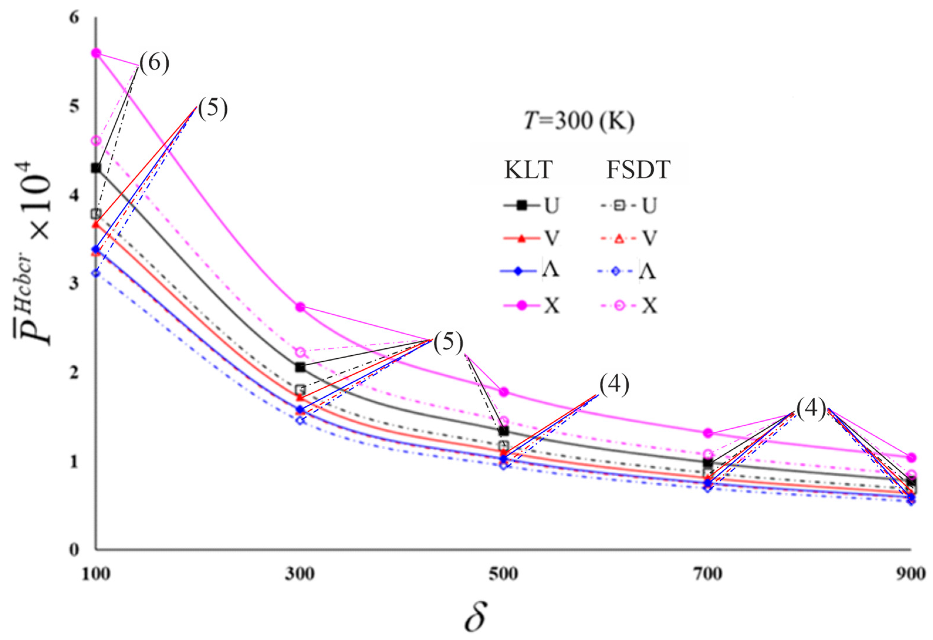
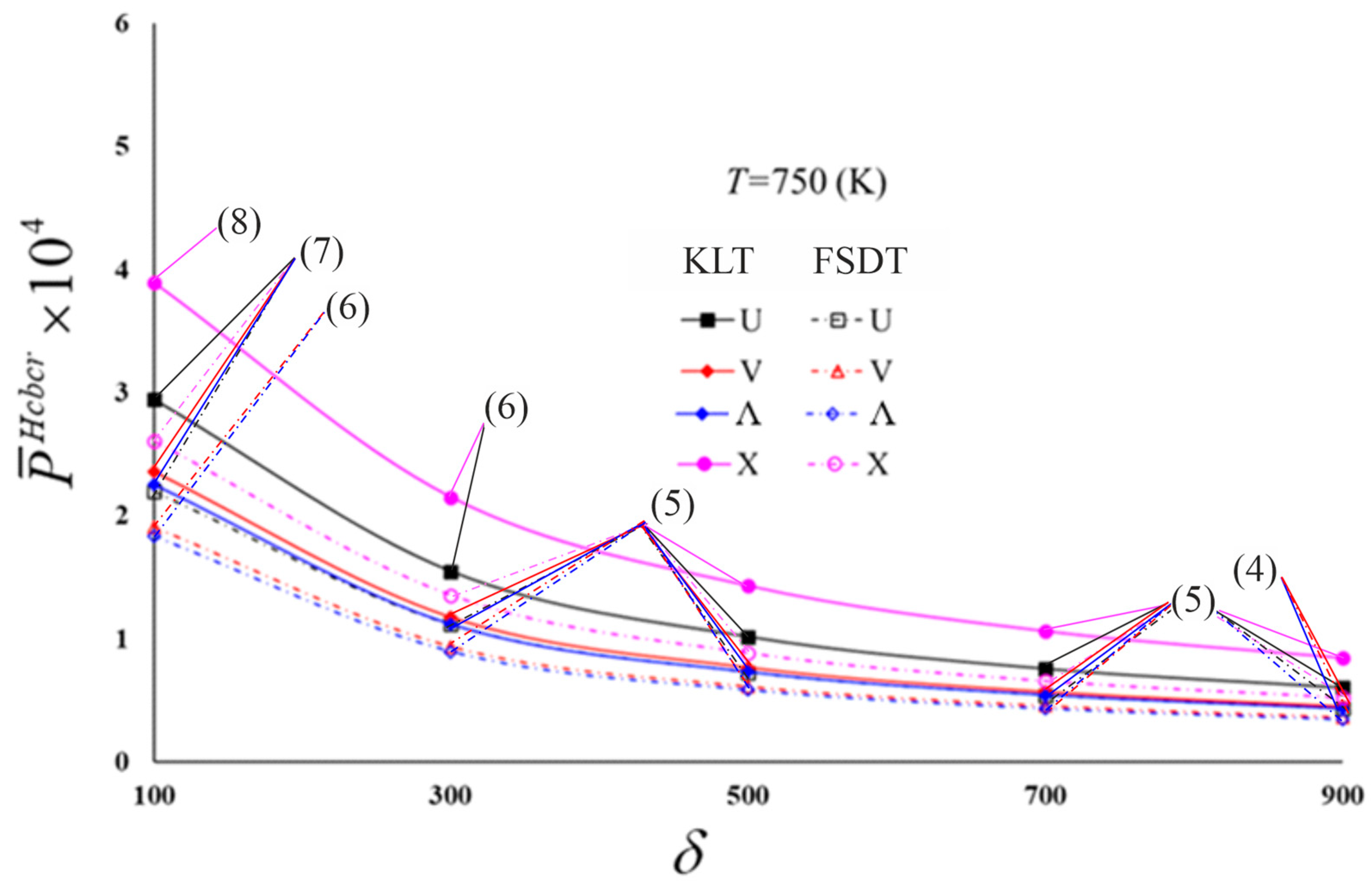
The most significant SDs effect on the critical combined load occurs in the X-model, and the least effect occurs in the Λ- and V-models.
(b)
The effect of temperature change on the critical combined load is more pronounced in the FSDT frame compared to the KLT.
(c)
While the increase in temperature change increases the effect of inhomogeneity on the critical combined load values in all models, considering the transverse shear strains significantly reduces the effects of the models.
(d)
The influence of transverse SDs on the P ¯ f s d t H c b c r changes irregularly for all models as the nondimensional load-proportional parameter rises.
(e)
The magnitudes of the nondimensional critical combined load and the corresponding circumferential wave numbers of four types of CNT-patterned cylindrical shells in thermal environments within two theories reduce as the nondimensional load-proportional parameter rises.
(f)
A consideration of the transverse SDs significantly rises the effect of temperature on the critical combined load.
(g)
In some cases, the difference of the influence of temperature on the critical combined load within the framework of FSDT and KLT is up to 13%.
(h)
Increasing the a / r ratio significantly reduces the values of nondimensional critical combined loads, whereas corresponding wave numbers decrease slightly.
(i)
At the small a / r , the influence of transverse SDs on the P ¯ f s d t H c b c r is quite large and is more likely to damage the structure.
(j)
The increase in the a / r significantly reduces the influence of transverse shear strains on the critical combined load at the fixed value of the r / t .
(k)
Although the effects of SDs on the P ¯ f s d t H c b c r for different models decrease when the a / r rises, the model types maintain their sensitivity.
(l)
Increasing the temperature significantly rises the SDs effect, as well as decreasing the rate of reduction in the SDs effect, which decreases with the increase in a / r .
(m)
The influence of the temperature is quite significant when the a / r ratio is small, the effect within FSDT is quite prominent compared to KLT, and the difference reduces as the a / r ratio increases.

Author Contributions

Conceptualization, M.A.; methodology, M.A.; software, M.A.; validation, M.A. and N.F.; formal analysis, M.A.; investigation, M.A.; resources, M.A.; writing—original draft preparation, M.A.; writing—review and editing, M.A., N.F., and A.H.S. All authors have read and agreed to the published version of the manuscript.

Funding

This article received no funding support.

Institutional Review Board Statement

Not applicable.

Informed Consent Statement

Not applicable.

Data Availability Statement

No data were reported in this study.

Conflicts of Interest

The authors declare no potential conflict of interest with respect to the research, authorship, and publication of this article.

Abbreviations

Symbols
a Length of cylindrical shell
e j ( j = 1 , 2 , 3 ) Efficiency parameters for CNTs
e x x ,   e y y ,     γ 0 x y Strain components at the mid-surface
f Shear stress shape function
F j ( z , T ) ( j = 1 , 2 ) Parameters including shear moduli and shear shape function
C i j , , D i j , H i j i 1 , Q i j i 1 Parameters depending on nanocomposite shell characteristics
K i Unknown amplitudes
L i j Differential operators
m Longitudinal wave number
m C N Mass of the CNT
M i j , M i i T   ( i = 1 , 2 ) Moments and thermal moments, respectively
n Circumferential wave number
n c r Circumferential wave numbers corresponding to critical loads
N i j , N i i T ( i = 1 , 2 ) Forces and thermal forces, respectively
N i j 0 ( i = 1 , 2 ) Membrane forces for the condition with zero initial moments
N a x Axial compressive load
N ¯ f s d t a x c r Nondimensional critical axial load within FSDT
N ¯ Nondimensional axial compressive load
P H c b c r Critical combined load
P ¯ L ,     P ¯ H Nondimensional lateral and hydrostatic pressures, respectively
P j ( j = 1 , 2 ) Uniform external pressures
P L , P H Lateral and hydrostatic pressures, respectively
P ¯ f s d t L c r , P ¯ k l t L c r Nondimensional critical lateral pressure within FSDT and KLT
P ¯ f s d t H c r , P ¯ k l t H c r Nondimensional critical hydrostatic pressure within FSDT and KLT
P ¯ f s d t H c b c r , P ¯ k l t H c b c r Nondimensional combined loads within FSDT and KLT
Q i Shear forces
r Radius of the cylindrical shell
t Thickness of the cylindrical shell
T Temperature
T 0 Reference temperature in which thermal strains are absent
Δ T Temperature rise
u ,   v , w Displacements in the x , y , z directions, respectively
U ,   Λ ,   X ,   V 
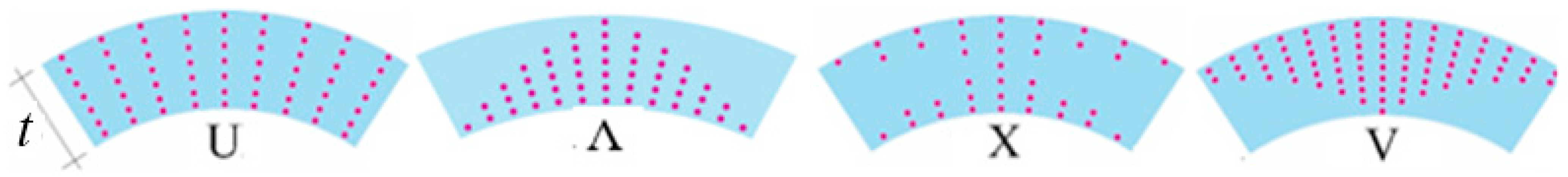
Patterns or CNT distribution in the matrix
V * C N Total volume fraction
V C N , V m Volume fraction of CNTs and polymer matrix, respectively
Y i i T ( Z , T ) , G i j T ( Z , T ) ( i = 1 , 2 , j = 1 , 2 , 3 ) Normal and shear elastic moduli of nanocomposites
Y i i T C N , G i j T C N ( i = 1 , 2 , j = 1 , 2 , 3 ) Normal and shear elastic moduli of CNT
Y ¯ i j ( Z , T ) ,     ( i , j = 1 , 2 , 6 ) Parameter containing elastic properties
Y T m , G T m Normal and shear elastic moduli of polymer matrix
x , y , z Coordinate axes
α 11 T C N ,     α 22 T C N Thermal expansion coefficients of CNTs
α T m Thermal expansion coefficients of the polymer
δ Nondimensional load-proportional parameter
Γ j   ( j = 3 , 4 ) Coefficients that depend on the shear stress shape function
ε j j ( j = x , y ) , γ i j ( i , j = x , y , z ) Strain components
Λ i Cofactors
μ i Parameters depending on wave numbers and shell properties
ν 12 ,   ν 21 Poisson’s ratios of nanocomposites
ν 12 C N , ν m Poisson’s ratios of CNTs and polymer, respectively
ρ Density of the nanocomposite
ρ C N , ρ m Densities of CNT and matrix, respectively
σ i j ( i , j = x , y , z ) Stress components
σ x Average axial compressive load
Φ Parameter including properties of nanocomposite cylindrical shell
Ψ Airy stress function
ψ 1 , ψ 2 Rotations of mid-surface normal about y and x axes, respectively
Abbreviation
CNTCarbon nanotube
KLTKirchhoff–Love theory
FSDTFirst-order shear deformation theory
INH-NCCSsInhomogeneous nanocomposite cylindrical shells
NCsNanocomposites
PaPascal, unit of Young’s modulus
KKelvin
SDsShear deformations
SWCNTsSingle-walled carbon nanotubes

Appendix A

Here, L i j   ( i , j = 1 , 2 , , 4 ) are differential operators and are defined as follows:
L 11 = t D 11 D 31 4 x 2 y 2 + D 12 4 x 4 ,       L 12 = D 13 4 x 4 D 14 + D 32 4 x 2 y 2 ,   L 13 = D 15 3 x 3 + D 35 3 x y 2 Γ 3 x ,       L 14 = D 18 + D 38 3 x 2 y L 21 = t D 21 4 y 4 + t D 22 D 31 4 x 2 y 2 ,       L 22 = D 32 + D 23 4 x 2 y 2 D 24 4 y 4 ,   L 23 = D 35 + D 25 3 x y 2 ,       L 24 = D 38 3 x 2 y + D 28 3 y 3 Γ 4 y L 31 = t C 11 4 y 4 + C 12 + C 21 + C 31 4 x 2 y 2 + C 22 4 x 4 L 32 = 1 r 2 x 2     C 23 4 x 4 C 24 + C 13 C 32 4 x 2 y 2 C 14 4 y 4 L 33 = C 25 3 x 3 + C 15 + C 35 3 x y 2 ,       L 34 = C 28 + C 38 3 x 2 y + C 18 3 y 3   L 41 = t r 2 x 2 ,       L 42 = N a x 2 x 2 P 1 2 2 x 2 + P 2 2 y 2 r ,     L 43 = Γ 3 x ,       L 44 = Γ 4 y .    
where Γ j = f t / 2 f t / 2 ,     j = 3 , 4 and the following definitions apply:
D 11 = H 11 1 C 11 + H 12 1 C 21 ,     D 12 = H 11 1 C 12 + H 12 1 C 22 ,     D 13 = H 11 1 C 13 + H 12 1 C 23 + H 11 2       D 14 = H 11 1 C 14 + H 12 1 C 24 + H 12 2 ,     D 15 = H 11 1 C 15 + H 12 1 C 25 + H 15 1 , D 18 = H 11 1 C 18 + H 12 1 C 28 + H 18 1 ,     D 21 = H 21 1 C 11 + H 22 1 C 21 , D 22 = H 21 1 C 12 + H 22 1 C 22 ,   D 23 = H 21 1 C 13 + H 22 1 C 23 + H 21 2 ,     D 24 = H 21 1 C 14 + H 22 1 C 24 + H 22 2 ,       D 25 = H 21 1 C 15 + H 22 1 C 25 + H 25 1 ,     D 28 = H 21 1 C 18 + H 22 1 C 28 + H 28 1 , D 31 = H 66 1 C 31 ,       D 32 = H 66 1 C 32 + 2 H 66 2 ,         D 35 = H 35 1 H 66 1 C 35 ,       D 38 = H 38 1 H 66 1 C 38 , C 11 = H 22 0 H ,     C 12 = H 12 0 H ,     C 13 = H 12 0 H 21 1 H 11 1 H 22 0 H ,     C 14 = H 12 0 H 22 1 H 12 1 H 22 0 H ,     C 15 = H 25 0 H 12 0 H 15 0 H 22 0 H , C 18 = H 28 0 H 12 0 H 18 0 H 22 0 H ,     C 21 = H 21 0 H ,     C 22 = H 11 0 H ,     C 23 = H 11 1 H 21 0 H 21 1 H 11 0 H ,     C 24 = H 12 1 H 21 0 H 22 1 H 11 0 H , C 25 = H 15 0 H 21 0 H 25 0 H 11 0 H ,       C 31 = 1 H 66 0 ,   C 28 = H 18 0 H 21 0 H 28 0 H 11 0 H ,     C 32 = 2 H 66 1 H 66 0 ,     C 35 = H 35 0 H 66 0 , C 38 = H 38 0 H 66 0 ,   H = H 11 0 H 22 0 H 12 0 H 21 0 .
in which
H 11 i 1 =   h / 2 h / 2 Y ¯ 11 ( Z , T ) z i 1 d z ,       H 12 i 1 =     h / 2 h / 2 Y ¯ 12 ( Z , T ) z i 1 d Z =     h / 2 h / 2 Y ¯ 21 ( Z , T ) z i 1 d z = H 21 i 1 ,       H 22 i 1 = h / 2 h / 2 Y ¯ 22 ( Z , T ) z i 1 d z , H 66 i 1 =   h / 2 h / 2 Y ¯ 66 ( Z , T ) z i 1 d z ,       H 15 i 2 = h / 2 h / 2 Y ¯ 11 ( Z , T ) F 1 ( z , T ) z i 2 d z ,           H 18 i 2 = h / 2 h / 2 Y ¯ 12 ( Z , T ) F 2 ( z , T ) z i 2 d z , H 25 i 2 = h / 2 h / 2 Y ¯ 21 ( Z , T ) F 1 ( z , T ) z i 2 d z ,           H 28 i 2 = h / 2 h / 2 Y ¯ 22 ( Z , T ) F 2 ( z , T ) z i 2 d z ,     H 35 i 2 = h / 2 h / 2 Y ¯ 66 ( Z , T ) F 1 ( z , T ) z i 2 d z ,   H 38 i 2 = h / 2 h / 2 Y ¯ 66 ( Z , T ) F 2 ( z , T ) z i 2 d z ,     i 1 = 0 ,   1 ,   2 ;   i 2 = 0 , 1 .

Appendix B

Q i j ( i , j = 1 , 2 , 3 , 4 ) are given by
Q 11 = t D 11 D 31 μ 1 2 μ 2 2 + D 12 μ 1 4 ,         Q 12 = D 14 + D 32 μ 1 2 μ 2 2 + D 13 μ 1 4 , Q 13 = D 15 μ 1 3 + D 35 μ 1 μ 2 2 + Λ 3 μ 1 ,   Q 14 = ( D 18 + D 38 ) μ 2 μ 1 2 ,       Q 21 = t D 21 μ 2 4 + D 22 D 31 μ 1 2 μ 2 2 ,       Q 22 = D 32 + D 23 μ 1 2 μ 2 2 + D 24 μ 2 4 ,       Q 23 = ( D 25 + D 35 ) μ 1 μ 2 2 ,     Q 24 = D 28 μ 2 3 + D 38 μ 1 2 μ 2 + Λ 4 μ 2 ,     Q 31 = t C 22 μ 1 4 + C 12 + C 21 + C 31 μ 1 2 μ 2 2 + C 11 μ 2 4 , Q 32 = C 23 μ 1 4 + C 24 + C 13 + C 32 μ 1 2 μ 2 2 + C 14 μ 2 4 + μ 1 2 / r , Q 33 = C 25 μ 1 3 + ( C 15 + C 35 ) μ 1 μ 2 2 ,     Q 34 = ( C 28 + C 38 ) μ 1 2 μ 2 + C 18 μ 2 3 ,     Q 41 = μ 1 2 t / r ,     Q 42 = N a x μ 1 2 + 0.5 P 1 μ 1 2 r + P 2 μ 2 2 ,       Q 43 = Λ 3 μ 1 ,         Q 44 = Λ 4 μ 2

References

  1. Volmir, A.S. Stability of Elastic Systems; Nauka: Moscow, Russia, 1967. [Google Scholar]
  2. Shen, H.S.; Chen, T.Y. Buckling and postbuckling behaviour of cylindrical shells under combined external pressure and axial compression. Thin-Walled Struct. 1991, 12, 321–334. [Google Scholar] [CrossRef]
  3. Anastasiadis, J.S.; Tabiei, A.; Simitses, G.J. Instability of moderately thick, laminated, cylindrical-shells under combined axial-compression and pressure. Compos. Struct. 1994, 27, 367–378. [Google Scholar] [CrossRef]
  4. Winterstetter, T.A.; Schmidt, H. Stability of circular cylindrical steel shells under combined loading. Thin-Walled Struct. 2002, 40, 893–910. [Google Scholar] [CrossRef]
  5. Tafresi, A.; Bailey, C.G. Instability of imperfect composite cylindrical shells under combined loading. Compos. Struct. 2007, 80, 49–64. [Google Scholar] [CrossRef]
  6. Praveen, A.P.; Rajamohan, V.; Mathew, A.T. Recent developments in investigation on buckling and post buckling responses of laminated composite shells. Polymer Compos. 2018, 39, 4231–4242. [Google Scholar] [CrossRef]
  7. Yang, L.C. Analytical investigation on the buckling of cylindrical shells under combined non-uniform axial compression and external pressure. Proc. Inst. Mech. Eng Part C-J. Mech. Eng. Sci. 2023. [Google Scholar] [CrossRef]
  8. Iijima, S. Synthesis of carbon nanotubes. Nature 1991, 354, 56–58. [Google Scholar] [CrossRef]
  9. Yu, M.F. Fundamental mechanical properties of carbon nanotubes: Current understanding and the related experimental studies. J. Eng. Mater. Techn. ASME 2004, 126, 271–278. [Google Scholar] [CrossRef]
  10. Hayashi, T.; Kim, Y.A.; Natsuki, T.; Endo, M. Mechanical properties of carbon nanomaterials. Chemphyschem 2007, 8, 999–1004. [Google Scholar] [CrossRef]
  11. Suzuki, K.; Nomura, S. On elastic properties of single-walled carbon nanotubes as composite reinforcing fillers. J. Compos. Mater. 2007, 41, 1123–1135. [Google Scholar] [CrossRef]
  12. Lu, J.Q.; Jiang, H. Theoretical modeling on mechanical-electrical coupling of carbon nanotubes. J. Computat. Theoret. Nanosci. 2008, 5, 449–463. [Google Scholar] [CrossRef]
  13. Xu, S.; Ray, G.; Abdel-Magid, B. Thermal behavior of single-walled carbon nanotube polymer–matrix composites. Compos. Part A 2006, 37, 114–121. [Google Scholar] [CrossRef]
  14. Cai, D.Y.; Song, M. Recent advance in functionalized graphene/polymer nanocomposites. J. Mater. Chem. 2010, 20, 7906–7915. [Google Scholar] [CrossRef]
  15. Su, L.S.; Tsai, J.L. Characterizing the mechanical properties of nanocomposites with aligned graphene. Polym. Compos. 2021, 42, 4005–4014. [Google Scholar] [CrossRef]
  16. Yadav, A.; Kumar, A.; Sharma, K.; Pandey, A.K. Determination of elastic constants of functionalized graphene-based epoxy nanocomposites: A molecular modeling and MD simulation study. J. Mol. Model. 2022, 8, 143. [Google Scholar] [CrossRef] [PubMed]
  17. Nurazzi, M.N.; Asyraf, M.R.M.; Khalin, A.; Abdullah, N.; Sabaruddin, F.A.; Kamarudin, S.H.; Ahmad, S.; Mahat, A.M.; Lee, C.L.; Aisyah, H.A.; et al. Fabrication, functionalization, and application of carbon nanotube-reinforced polymer composite: An overview. Polymers 2021, 13, 1047. [Google Scholar] [CrossRef]
  18. Lim, B.K.; Hwang, J.W.; Lee, D.; Hong, S.H. Fabrication processes and multi-functional applications of carbon nanotube nanocomposites. J. Compos Mater. 2012, 46, 1731–1737. [Google Scholar] [CrossRef]
  19. Meer, S.; Kausar, A.; Iqbal, T. Trends in conducting polymer and hybrids of conducting polymer/carbon nanotube: A Review. Polym.-Plast. Technol. Eng. 2016, 55, 1416–1440. [Google Scholar] [CrossRef]
  20. Fantuzzi, N.; Bacciocchi, M.; Agnelli, J.; Benedetti, D. Three-phase homogenization procedure for woven fabric composites reinforced by carbon nanotubes in thermal environment. Compos. Struct. 2020, 254, 112840. [Google Scholar] [CrossRef]
  21. Vartak, D.A.; Satyanarayana, B.; Munjal, B.S.; Vyas, K.B.; Bhatt, P.; Lal, A.K. Potential applications of advanced nano-composite materials for space payload. Aust. J. Mech. Eng. 2022, 20, 651–659. [Google Scholar] [CrossRef]
  22. Anashpaul, S.; Drosopoulos, G.A.; Adali, S. Minimum weight design of CNT/fiber reinforced laminates subject to a frequency constraint by optimal distribution of reinforcements across the thickness. Compos. Struct. 2023, 319, 117112. [Google Scholar] [CrossRef]
  23. Shen, H.-S. Postbuckling of nanotube-reinforced composite cylindrical shells in thermal environments, Part I: Axially-loaded shells. Compos. Struct. 2011, 93, 2096–2108. [Google Scholar] [CrossRef]
  24. Shen, H.-S. Postbuckling of nanotube-reinforced composite cylindrical shells in thermal environments, Part II: Pressure-loaded shells. Compos. Struct. 2011, 93, 2496–2503. [Google Scholar] [CrossRef]
  25. Shen, H.-S.; Xiang, Y. Postbuckling of nanotube-reinforced composite cylindrical shells under combined axial and radial mechanical loads in thermal environment. Compos. B Eng. 2013, 52, 311–322. [Google Scholar] [CrossRef]
  26. Hajlaoui, A.; Chebbi, E.; Dammak, F. Buckling analysis of carbon nanotube reinforced FG shells using an efficient solid-shell element based on a modified FSDT. Thin-Walled Struct. 2019, 144, 106254. [Google Scholar] [CrossRef]
  27. Hieu, P.T.; Tung, H.V. Postbuckling behavior of CNT-reinforced composite cylindrical shell surrounded by an elastic medium and subjected to combined mechanical loads in thermal environments. J. Thermoplast. Compos. Mater. 2019, 32, 1319–1346. [Google Scholar] [CrossRef]
  28. Sofiyev, A.H.; Tornabene, F.; Dimitri, R.; Kuruoglu, N. Buckling behavior of FG-CNT reinforced composite conical shells subjected to a combined loading. Nanomaterials 2020, 10, 419. [Google Scholar] [CrossRef]
  29. Monaco, G.T.; Fantuzzi, N.; Fabbrocino, F.; Luciano, R. Trigonometric solution for the bending analysis of magneto-electro-elastic strain gradient nonlocal nanoplates in hygro-thermal environment. Mathematics 2021, 9, 567. [Google Scholar] [CrossRef]
  30. Monaco, G.T.; Fantuzzi, N.; Fabbrocino, F.; Luciano, R. Critical temperatures for vibrations and buckling of magneto-electro-elastic nonlocal strain gradient plates. Nanomaterials 2021, 11, 87. [Google Scholar] [CrossRef]
  31. Cornacchia, F.; Fabbrocino, F.; Fantuzzi, N.; Luciano, R.; Penna, R. Analytical solution of cross- and angle-ply nano plates with strain gradient theory for linear vibrations and buckling. Mech. Adv. Mater. Struct. 2021, 28, 1201–1215. [Google Scholar] [CrossRef]
  32. Sofiyev, A.H.; Kuruoglu, N. Buckling analysis of shear deformable composite conical shells reinforced by CNTs subjected to combined loading on the two-parameter elastic foundation. Defence Techn. 2022, 18, 205–218. [Google Scholar] [CrossRef]
  33. Avey, M.; Fantuzzi, N.; Sofiyev, A.H. Mathematical modeling and analytical solution of thermoelastic stability problem of functionally graded nanocomposite cylinders within different theories. Mathematics 2022, 10, 1081. [Google Scholar] [CrossRef]
  34. Sun, G.X.; Zhu, S.B.; Teng, R.; Sun, J.; Zhou, Z.; Xu, X.S. Post-buckling analysis of GPLs reinforced porous cylindrical shells under axial compression and hydrostatic pressure. Thin-Walled Struct. 2022, 172, 108834. [Google Scholar] [CrossRef]
  35. Hieu, D.V.; Phi, B.G.; Sedighi, H.M.; Sofiyev, A.H. Size-dependent nonlinear vibration of functionally graded composite micro-beams reinforced by carbon nanotubes with piezoelectric layers in thermal environments. Acta Mech. 2022, 233, 2249–2270. [Google Scholar]
  36. Li, C.; Zhu, C.X.; Lim, C.W.; Li, S. Nonlinear in-plane thermal buckling of rotationally restrained functionally graded carbon nanotube reinforced composite shallow arches under uniform radial loading. Appl. Math. Mech. 2022, 43, 1821–1840. [Google Scholar] [CrossRef]
  37. Kumar, R.; Kumar, A.; Kumar, D.R. Buckling response of CNT based hybrid FG plates using finite element method and machine learning method. Compos. Struct. 2023, 319, 117204. [Google Scholar] [CrossRef]
  38. Kumar, S.; Ramesh, M.R.; Jeyaraj, P.; Doddamani, M. Buckling and dynamic responses of 3D printed nanocomposites and their graded variants. Compos. Struct. 2023, 316, 117031. [Google Scholar] [CrossRef]
  39. Tomczyk, B.; Bagdasaryan, V.; Gołąbczak, M.; Litawska, A. A new combined asymptotic-tolerance model of thermoelasticity problems for thin biperiodic cylindrical shells. Compos. Struct. 2023, 309, 116708. [Google Scholar] [CrossRef]
  40. Yang, Z.; Zhao, S.; Yang, J.; Liu, A.; Fu, J. Thermomechanical in-plane dynamic instability of asymmetric restrained functionally graded graphene reinforced composite arches via machine learning-based models. Compos. Struct. 2023, 308, 116709. [Google Scholar] [CrossRef]
  41. Avey, M.; Fantuzzi, N.; Sofiyev, A.H. Thermoelastic stability of CNT patterned conical shells under thermal loading in the framework of shear deformation theory. Mech. Adv. Mater. Struct. 2023, 30, 1828–1841. [Google Scholar] [CrossRef]
  42. Chakraborty, S.; Dey, T. Thermomechanical buckling and wrinkling characteristics of softcore sandwich panels with CNT reinforced composite face sheets. Euro. J. Mech. A-Solid. 2023, 98, 104894. [Google Scholar] [CrossRef]
  43. Sofiyev, A.H.; Fantuzzi, N. Stability analysis of shear deformable inhomogeneous nanocomposite cylindrical shells under hydrostatic pressure in thermal environment. Materials 2023, 16, 4887. [Google Scholar] [CrossRef]
  44. Dong, D.T.; Phuong, N.T.; Nam, V.H.; Ly, L.N.; Tien, N.V.; Duc, V.M.; Minh, T.Q.; Hung, V.T.; Giang, N.T.H. An analytical approach for nonlinear buckling analysis of torsionally loaded sandwich carbon nanotube reinforced cylindrical shells with auxetic Core. Adv. Appl. Math. Mech. 2023, 15, 468–484. [Google Scholar] [CrossRef]
  45. Shen, H.-S.; Noda, N. Postbuckling of FGM cylindrical shells under combined axial and radial mechanical loads in thermal environments. Int. J. Solid. Struct. 2005, 42, 4641–4662. [Google Scholar] [CrossRef]
  46. Sofiyev, A.H. Buckling analysis of FGM circular shells under combined loads and resting on the Pasternak type elastic foundation. Mech. Res. Communic. 2010, 37, 539–544. [Google Scholar] [CrossRef]
  47. Ambartsumian, S.A. Theory of Anisotropic Shells; NASA-TT-F-118; NASA: Washington, DC, USA, 1964.
  48. Shen, H.-S.; Wang, H.; Yang, D.Q. Vibration of thermally postbuckled sandwich plates with nanotube reinforced composite face sheets resting on elastic foundations. Int. J. Mech. Sci. 2017, 124–125, 253–262. [Google Scholar] [CrossRef]
  49. Griebel, M.; Hamaekers, J. Molecular dynamics simulations of the elastic moduli of polymer–carbon nanotube composites. Comput. Methods Appl. Mech. Eng. 2004, 193, 1773–1788. [Google Scholar] [CrossRef]
  50. Han, Y.; Elliott, J. Molecular dynamics simulations of the elastic properties of polymer/carbon nanotube composites. Comput. Mater. Sci. 2007, 39, 315–323. [Google Scholar] [CrossRef]
Figure 1. Nanocomposite cylindrical shell with different CNT models subjected to the combined load.
Mathematics 11 03781 g001
Figure 2. Shapes of the uniform and inhomogeneous distributions of CNTs in the thickness direction of the polymer matrix.
Mathematics 11 03781 g002
Figure 3. Distribution of P ¯ f s d t H c b c r and P ¯ k l t H c b c r for nanocomposite cylindrical shells with various models versus the δ at T = 300 (K).
Mathematics 11 03781 g003
Figure 4. Distribution of P ¯ f s d t H c b c r and P ¯ k l t H c b c r for nanocomposite cylindrical shells with various models versus the δ at T = 750 (K).
Mathematics 11 03781 g004
Figure 5. Distribution P ¯ k l t H c b c r for nanocomposite cylindrical shells with various models versus the δ for different temperatures.
Mathematics 11 03781 g005
Figure 6. Distribution of P ¯ f s d t H c b c r for nanocomposite cylindrical shells with various models versus the δ for different temperatures.
Mathematics 11 03781 g006
Figure 7. Distribution of P ¯ k l t H c b c r for nanocomposite cylindrical shells with various models in the thermal environment versus the a / r .
Mathematics 11 03781 g007
Figure 8. Distribution of P ¯ f s d t H c b c r for nanocomposite cylindrical shells with various models in the thermal environment versus the a / r .
Mathematics 11 03781 g008
Table 1. The temperature-dependent material properties of (10, 10) SWCNTs.
Temperature (K) Y 11 T C N
(TPa)
Y 22 T C N
(TPa)
G 12 T C N
(TPa)
α 11 T C N × 10 6 / K α 22 T C N × 10 6 / K
3005.64517.07962.06653.45795.1682
4505.54616.95632.37284.37585.0539
6005.49946.89842.92834.68524.9535
7505.45886.84823.83254.61524.8670
Table 2. Typical values of CNT efficiency parameters.
CNT Efficiency Parameters
  V * C N e 1 e 2 e 3
0.120.1371.6260.715
0.170.1421.6261.138
0.230.1411.5851.109
Table 3. Comparative study of P f s d t L c b c r for INH-NCCSs with the X-model with different load-proportional parameters.
P f s d t L c b c r ( MPa )   ( n c r = 4 ) for X-Model
T = 300 (K)T = 400 (K)T = 500 (K)
δ = 750 δ = 140 δ = 750 δ = 140 δ = 750 δ = 140
V * C N Shen and Xiang [25]
0.120.1120.2180.0980.1910.0840.166
0.170.1900.3700.1670.3250.1430.280
0.280.2420.4700.2130.4140.1830.358
V * C N Present study
0.120.1100.2220.0970.1960.0840.169
0.170.1870.3790.1650.3330.1420.286
0.280.2400.4860.2110.4270.1820.368
Table 4. Comparative study of P f s d t L c r for PMMA-based nanocomposite cylindrical shells with different CNT models.
P f s d t L c r ( n c r )
a Comparative StudiesUX
10 r t Present study775.23 (5)893.46 (5)
Shen [24]776.63 (5)927.40 (5)
Hajlaoui et al. [26]763.46 (5)886.32 (5)
10 3 r t Present study433.18 (4)477.97 (4)
Shen [24]433.04 (4)484.05 (4)
Hajlaoui et al. [26]438.47 (4)482.39 (4)
10 5 r t Present study344.02 (4)379.43 (4)
Shen [24]343.81 (4)382.59 (4)
Hajlaoui et al. [26]346.77 (4)381.51 (4)
Table 5. Distribution of P ¯ f s d t H c b c r and P ¯ k l t H c b c r for CNT-reinforced polymer-based cylindrical shells and corresponding wave numbers versus the δ load-proportional parameter in thermal environments.
P ¯ H c b c r × 10 4 ( n c r )
T = 300 (K)
UVΛX
δ KLTFSDTKLTFSDTKLTFSDTKLTFSDT
1004.303 (6)3.792 (6)3.677 (5)3.367 (5)3.388 (5)3.116 (5)5.599 (6)4.612 (6)
3002.059 (5)1.804 (5)1.720 (5)1.575 (5)1.585 (5)1.458 (5)2.737 (5)2.231 (5)
5001.344 (5)1.177 (5)1.109 (4)1.020 (4)1.030 (4)0.951 (4)1.786 (5)1.456 (5)
7000.991 (4)0.870 (4)0.815 (4)0.749 (4)0.756 (4)0.698 (4)1.322 (4)1.079 (4)
9000.783 (4)0.688 (4)0.644 (4)0.592 (4)0.598 (4)0.552 (4)1.044 (4)0.853 (4)
δ T = 450 (K)
1003.873 (6)3.309 (6)3.247 (6)2.920 (6)3.031 (6)2.738 (5)5.096 (7)4.035 (6)
3001.882 (5)1.595 (5)1.531 (5)1.373 (5)1.423 (5)1.280 (5)2.542 (5)1.975 (5)
5001.228 (5)1.041 (5)0.993 (4)0.893 (4)0.929 (5)0.836 (5)1.659 (5)1.289 (5)
7000.910 (4)0.773 (5)0.729 (4)0.656 (4)0.683 (4)0.616 (4)1.232 (5)0.960 (4)
9000.719 (4)0.611 (4)0.576 (4)0.518 (4)0.539 (4)0.487 (4)0.975 (4)0.758 (4)
δ T = 600 (K)
1003.453 (7)2.804 (6)2.805 (6)2.435 (6)2.642 (6)2.304 (6)4.544 (7)3.398 (7)
3001.716 (5)1.374 (5)1.351 (5)1.166 (5)1.269 (5)1.099 (5)2.366 (5)1.697 (5)
5001.120 (5)0.897 (5)0.882 (5)0.761 (5)0.828 (5)0.717 (5)1.544 (5)1.107 (5)
7000.831 (5)0.666 (5)0.648 (4)0.561 (4)0.613 (4)0.532 (4)1.146 (5)0.822 (5)
9000.659 (4)0.529 (4)0.512 (4)0.443 (4)0.484 (4)0.421 (4)0.911 (5)0.653 (4)
δ T = 750 (K)
1002.941 (7)2.195 (7)2.351 (7)1.908 (6)2.253 (7)1.828 (6)3.887 (8)2.602 (7)
3001.544 (6)1.113 (5)1.171 (5)0.935 (5)1.116 (5)0.895 (5)2.148 (6)1.352 (5)
5001.013 (5)0.726 (5)0.764 (5)0.610 (5)0.728 (5)0.584 (5)1.430 (5)0.883 (5)
7000.752 (5)0.539 (5)0.567 (5)0.453 (5)0.541 (5)0.433 (5)1.062 (5)0.656 (5)
9000.598 (5)0.429 (5)0.448 (4)0.359 (4)0.430 (4)0.345 (5)0.844 (5)0.521 (5)
Table 6. Distribution of critical combined loads and corresponding wave numbers of polymer-based cylindrical shells reinforced with the CNT in the thermal environment versus the a / r within two theories.
P ¯ H c b c r × 10 4
T = 300 (K)
UVOX
a / r KLTFSDTKLTFSDTKLTFSDTKLTFSDT
0.504.131 (5)2.397 (5)2.958 (4)2.001 (5)2.923 (5)1.978 (5)5.977 (6)2.839 (5)
0.752.033 (5)1.576 (5)1.566 (5)1.317 (5)1.491 (5)1.258 (5)2.837 (5)1.952 (5)
1.001.344 (5)1.177 (5)1.109 (4)1.020 (4)1.030 (4)0.951 (4)1.786 (5)1.456 (5)
1.251.034 (4)0.961 (4)0.909 (4)0.867 (4)0.821 (4)0.787 (4)1.318 (4)1.171 (4)
1.500.875 (4)0.838 (4)0.812 (4)0.788 (4)0.721 (4)0.704 (4)1.071 (4)0.996 (4)
a / r T = 450 (K)
0.503.977 (6)2.100 (5)2.815 (5)1.769 (5)2.786 (5)1.752 (5)5.779 (6)2.443 (6)
0.751.914 (5)1.403 (5)1.444 (5)1.168 (5)1.383 (5)1.122 (5)2.702 (5)1.723 (5)
1.001.228 (5)1.041 (5)0.993 (4)0.893 (4)0.929 (5)0.836 (5)1.659 (5)1.289 (5)
1.250.925 (4)0.842 (4)0.792 (4)0.746 (4)0.721 (4)0.682 (4)1.202 (4)1.034 (4)
1.500.765 (4)0.722 (4)0.692 (4)0.667 (4)0.619 (4)0.600 (4)0.954 (4)0.868 (4)
a / r T = 600 (K)
0.503.846 (6)1.753 (6)2.694 (5)1.506 (5)2.671 (6)1.495 (5)5.619 (7)1.994 (6)
0.751.809 (5)1.211 (5)1.331 (5)1.009 (5)1.286 (5)0.976 (5)2.585 (6)1.465 (5)
1.001.120 (5)0.897 (5)0.882 (5)0.761 (5)0.828 (5)0.717 (5)1.544 (5)1.107 (5)
1.250.820 (4)0.720 (4)0.678 (4)0.624 (4)0.624 (4)0.577 (4)1.090 (5)0.889 (4)
1.500.657 (4)0.606 (4)0.574 (4)0.545 (4)0.519 (4)0.496 (4)0.842 (4)0.738 (4)
a / r T = 750 (K)
0.503.709 (7)1.321 (6)2.573 (6)1.173 (5)2.550 (6)1.163 (6)5.427 (9)1.455 (6)
0.751.700 (6)0.967 (5)1.220 (5)0.816 (5)1.189 (5)0.797 (5)2.454 (6)1.136 (5)
1.001.013 (5)0.726 (5)0.764 (5)0.610 (5)0.728 (5)0.584 (5)1.430 (5)0.883 (5)
1.250.710 (5)0.580 (5)0.564 (6)0.494 (4)0.528 (4)0.464 (4)0.967 (5)0.711 (5)
1.500.549 (4)0.481 (4)0.456 (4)0.419 (4)0.419 (4)0.387 (4)0.729 (4)0.592 (4)
Disclaimer/Publisher’s Note: The statements, opinions and data contained in all publications are solely those of the individual author(s) and contributor(s) and not of MDPI and/or the editor(s). MDPI and/or the editor(s) disclaim responsibility for any injury to people or property resulting from any ideas, methods, instructions or products referred to in the content.

