Article

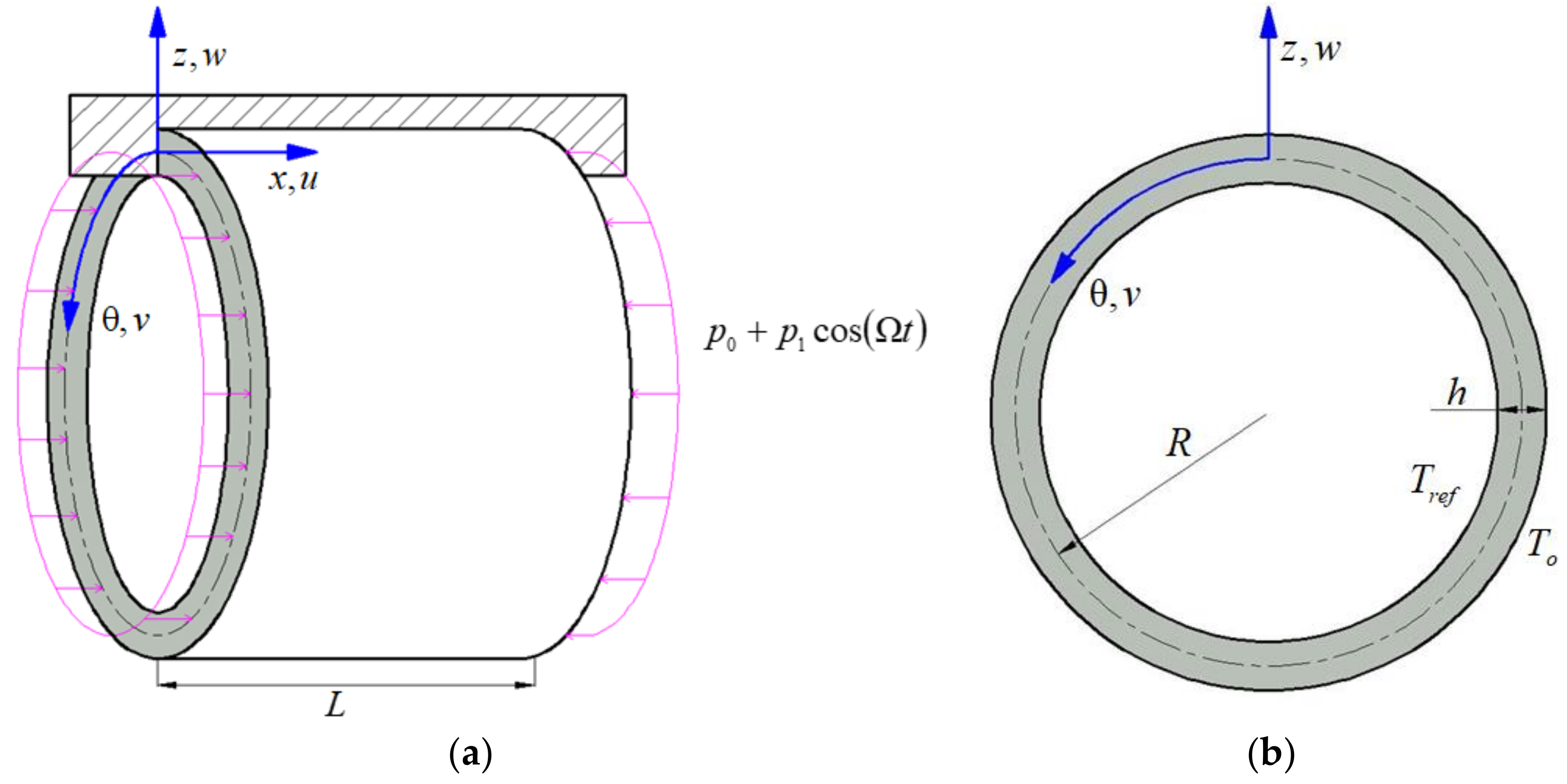
Static and Dynamic Stability of Carbon Fiber Reinforced Polymer Cylindrical Shell Subject to Non-Normal Boundary Condition with One Generatrix Clamped

1
College of Mechanical Engineering, Beijing Information Science and Technology University, Beijing 100192, China
2
Beijing Key Laboratory of Nonlinear Vibrations and Strength of Mechanical Structures, College of Mechanical Engineering, Beijing University of Technology, Beijing 100124, China
3
Department of Mechanics, Inner Mongolia University of Technology, Hohhot 010051, China
*
Author to whom correspondence should be addressed.
Mathematics 2022, 10(9), 1531; https://doi.org/10.3390/math10091531
Submission received: 15 March 2022 / Revised: 28 April 2022 / Accepted: 29 April 2022 / Published: 3 May 2022
(This article belongs to the Special Issue Modeling and Analysis in Dynamical Systems and Bistability)

Abstract

:
In this paper, static and dynamic stability analyses taking axial excitation into account are presented for a laminated carbon fiber reinforced polymer (CFRP) cylindrical shell under a non-normal boundary condition. The non-normal boundary condition is put forward to signify that both ends of the cylindrical shell are free and one generatrix of the shell is clamped. The partial differential motion governing the equations of the laminated CFRP cylindrical shell with a non-normal boundary condition is derived using the Hamilton principle, nonlinear von-Karman relationships and first-order deformation shell theory. Then, nonlinear, two-freedom, ordinary differential equations on the radial displacement of the cylindrical shell are obtained utilizing Galerkin method. The Newton-Raphson method is applied to numerically solve the equilibrium point. The stability of the equilibrium point is determined by analyzing the eigenvalue of the Jacobian matrix. The solution of the Mathieu equation describes the dynamic unstable behavior of the CFRP laminated cylindrical shells. The unstable regions are determined using the Bolotin method. The influences of the radial line load, the ratio of radius to thickness, the ratio of length to thickness, the number of layers and the temperature field of the laminated CFRP cylindrical shell on static and dynamic stability are investigated.

1. Introduction

Carbon fiber reinforced polymer (CFRP) laminates are widely used in many engineering fields, such as the ship, vehicle, and aerospace industries, because of their high strength, excellent material performance, light weight, high heat resistance and anti-corrosion properties. In recent years, scholars have carried out research on the mechanical properties of carbon fiber composite materials in order to expand their application range and maintain their reliability [1,2,3]. The stability characteristics of structures made of CFRP ensure their security and reliability. In unstable conditions, the vibration amplitude of the structure is unbounded and increases exponentially with time. Since the resulting vibration may completely destroy the structural members, leading to structural mutations, predictions of structural stability are of the utmost importance from the point of view of both design and optimization [4]. Cylindrical shells are among the most widely used structures in many engineering fields, such as rocket and aircraft propulsion systems and large deployable space annular antenna [5,6]. Hence, it is necessary to understand and predict the nonlinear stability characteristics of CFRP laminated cylindrical shells.
Numerous investigations of the stability characteristics of beam, plate and shell structures have been published to date. Kiral et al. [7] described the dynamic stability of a composite cantilever beam under periodic axial load delamination at predetermined positions. Ke et al. [8] studied the dynamic stability of functionally graded microbeams. In that report, the effects of gradient index, length scale parameters, the slenderness ratio and end supports on static buckling, free vibrations and the dynamic stability of FGM microbeams are discussed in detail. Couto et al. [9] studied the influence of non-uniform bending on transverse torsional buckling of slender steel beams at high temperature. Talebitooti [10] studied the buckling of laminated conical shells made of composite materials under uniformly distributed external loads according to first-order shear deformation theory. Maali et al. [11] studied the buckling behavior of thin defective conical plates under basic supported conditions. Bich et al. [12] studied the linear buckling behavior of functionally graded tapered plates under axial and external pressures. Gajdzicki et al. [13] carried out research on the stability of bi-directionally corrugated plates under compression and shear. Zeng et al. [14] studied the stability and vibrations of rectangular plates with side cracks. Dey et al. [15] studied the dynamic instability and post-buckling behavior of a composite, supported cylindrical shell plate under dynamic local edge load and transverse patch load. Finally, Han et al. [16] studied the dynamic stability of cylindrical shells under periodic axial loads with varying rotational speeds.
However, while there are numerous studies on the dynamic response of carbon fiber composites, few have examined their stability characteristics. Kolanua et al. [17] investigated the stability behavior and failure characteristics of carbon fiber reinforced polymer (CFRP) composite panels with a secondary bonded blade stiffener under compression. The suitability of a CFRP plate subjected to low-velocity impacts for the estimation of the critical load of delamination onset and the approximation of the load-displacement curve are investigated by Salvetti et al. [18]. Cui et al. [19] studied the failure process of CFRP electromagnetic riveting joints under high-speed loading. The deformation and stress capacity of CFRP was studied by Zhang et al. [20]. Juntanalikit et al. [21] studied the cyclic performance of reinforced concrete columns with non-ductile CFRP jackets by experimental and numerical methods. Reuter et al. [22] studied the shear strength of GFRP tubular structures using novel simulation methods. Time et al. [23] studied the fire stability of a CFRP shell structure with a medium-sized test device. Zhang and Zhao [24,25,26] studied the nonlinear response of a laminated CFRP cantilever plate under the action of moment excitation, in-plane airflow and supersonic airflow.
Cylindrical shells are often used as structural units. Hwu et al. [27], Viswanathan et al. [28] and Sarkheil et al. [29] respectively studied the free vibrations of a composite sandwich plate and cylindrical shell, an anti-symmetric cylindrical shell and a cylinder-conical shell. The nonlinear vibrations of water-filled cylindrical shells were studied by Amabili et al. [30]. Song et al. [31] studied the vibration behavior of carbon nanotube-reinforced, composite, closed cylindrical shells using Reddy’s high-order shear deformation theory. Zhang et al. [32] studied the nonlinear dynamics of a clamped, functional gradient material cylindrical shell under complex combined loads. Du et al. [33] discussed the internal resonance behavior of FGM cylindrical shells under a thermal environment. Sun et al. [34] studied the multi-pulse chaotic motion of a circular grid antenna and the nonlinear dynamics of an equivalent cylindrical shell. Liu et al. [35] studied the nonlinear vibrations of composite cylindrical shells with radial prestretched films at the ends. Wang [36] studied the nonlinear vibrations of rotating, composite laminated cylindrical shells with large amplitudes near the lowest resonance under radial harmonic excitation. Hao et al. [37] studied the aerodynamic and thermoelastic flutter characteristics of ceramic-metal gradient truncated conical shells. Wang et al. [38,39] studied the nonlinear dynamic response of rotating cylindrical shells under spectral neighborhood harmonic excitation using numerical methods and approximate analytical solutions. Shen et al. [40,41] studied large amplitude, nonlinear vibrations of shear deformed FGM cylindrical shells surrounded by elastic media.
Non-normal boundary conditions, i.e., when both ends are free and one generatrix of the shell is clamped, often occur in cylindrical shells, e.g., large annular antenna structures. However, few researchers have studied the stability of cylindrical shells under non-positive boundary conditions. In the present research, nonlinear static and dynamic stability analyses of CFRP laminated cylindrical shells with non-normal boundary conditions are carried out. Based on von-Karman-type nonlinear relationships, FSDT and the Hamilton principle, the nonlinear dynamic equation of CFRP laminated cylindrical shells was established using the Galerkin method and expressed as an ordinary differential equation describing radial displacement. The newton-Raphson method is used to numerically analyze the equilibrium point, and local stability is determined by the eigenvalues of the Jacobian matrix. The solution of the Mathieu equation describes the dynamic unstable behavior of a CFRP laminated cylindrical shell. The correctness of the results in this paper is verified by comparisons with the existing results. The influence of radial line load, the ratio of radius to thickness, the ratio of length to thickness, the number of layers and the temperature field on the static and dynamic stability of a CFRP laminated cylindrical shell is studied by parameterization.

2. Equations of Motion

A mechanical model of carbon fiber-reinforced, polymer laminated, cylindrical shells with length L , middle surface radius R and uniform thickness h , as shown in Figure 1, is considered. There are N s layers with a ply stacking sequence of (45/−45)s. The curvilinear coordinate system x , θ , z is located in the mid-surface of the CFRP laminated cylindrical shell along the axial direction, the circumferential direction and the radial direction, respectively. Displacement components u , v and w represent the displacements of an arbitrary point in directions x , θ and z , respectively. Non-normal boundary of cylindrical shells which are free at both ends and clamped at θ = 0 , i.e., one of the longitudinal sections, are considered, as shown in Figure 1a. Figure 1b presents the sections of x = L and x = 0 . The temperatures of the cylindrical shell surface are T o and T r e f , respectively. Axial excitation P is loaded at both ends ( x = 0 , x = L ) of the CFRP laminated cylindrical shell.
P = p 0 + p 1 cos Ω t
where p 0 and p 1 cos Ω 2 t are static and dynamic harmonic excitation, respectively.
According to first-order shear deformation theory [42], it is assumed that the displacement field of CFRP laminated cylindrical shells is
u x , θ , z = u 0 x , θ + z φ x x , θ
v x , θ , z = v 0 x , θ + z φ θ x , θ
w x , θ , z = w 0 x , θ
where u 0 , v 0 and w 0 represent the mid-plane displacements in directions x , θ and z , respectively. φ x and φ θ denote radial rotations in the θ and x directions, respectively.
Displacement field Equations (2)–(4) is substituted into the von Karman geometric nonlinear strain-displacement relation [43], and the nonlinear strain is determined as:
ε x ε θ γ θ z = ε x 0 ε θ 0 γ x θ 0 + z ε x 1 ε θ 1 γ x θ 1 ,   γ θ z γ x z = φ θ + 1 R w 0 θ 1 R v 0 w 0 x + φ x
where
ε x 0 ε θ 0 γ x θ 0 = u 0 x + 1 2 w 0 x 2 1 R v 0 θ + 1 R w 0 + 1 2 R 2 w 0 θ 2 1 R u 0 θ + v 0 x + 1 R w 0 x w 0 θ ,   ε x 1 ε θ 1 γ x θ 1 = φ x x 1 R φ θ θ 1 R φ x θ + φ θ x
where ε x and ε θ are the principal strains, and γ x θ , γ θ z , and γ x z denote the shear strains.
The constitutive relationship of laminated CFRP cylindrical shell, considering thermal stress, may be written as
σ x σ θ σ x θ σ θ z σ x z k = Q ¯ 11 Q ¯ 12 0 0 0 Q ¯ 12 Q ¯ 22 0 0 0 0 0 Q ¯ 66 0 0 0 0 0 Q ¯ 44 0 0 0 0 0 Q ¯ 55 k ε x ε θ γ x θ γ θ z γ x z α x α θ 2 α x θ 0 0 Δ T z k
where Q ¯ i j   i , j = 1 , 2 , 4 , 5 , 6 are the stiffness coefficients, Δ T is the temperature increment, and α x , α θ and α x θ are the coefficients of thermal expansion, which are expressed by
α x = α 1 cos 2 β + α 2 sin 2 β
α θ = α 1 sin 2 β + α 2 cos 2 β
α x θ = α 1 α 2 sin β cos β
where α 1 and α 2 are the coefficients of the thermal expansion in the different material directions, respectively.
It is supposed that the laminated CFRP cylindrical shell is initially stress free at T r e f . Assuming that the temperature increment is linear, i.e.,
Δ T = T r e f + z h T 0 T r e f
then the stiffness coefficients Q ¯ i j are given by
{ Q ¯ 11 Q ¯ 12 Q ¯ 22 Q ¯ 16 Q ¯ 26 Q ¯ 66 } = { C 4 2 C 2 S 2 S 4 4 C 2 S 2 C 2 S 2 C 4 + S 4 C 2 S 2 4 C 2 S 2 S 4 2 C 2 S 2 C 4 4 C 2 S 2 C 3 S C S 3 C 3 S C S 3 2 C S C 2 S 2 C S 3 C 3 S C S 3 C 3 S 2 C S C 2 S 2 C 2 S 2 2 C 2 S 2 C 2 S 2 C 2 S 2 2 } { Q 11 Q 12 Q 22 Q 66 }
Q ¯ 44 Q ¯ 45 Q ¯ 55 = C 2 S 2 C S C S S 2 C 2 Q 44 Q 55 ,   C = cos β ,   S = sin β
where β is the ply angle of the laminated CFRP cylindrical shell. The stiffness coefficients of material Q i j are
Q 11 = E 1 1 ν 12 ν 21 ,   Q 12 = ν 12 E 2 1 ν 12 ν 21 ,   Q 22 = E 2 1 ν 12 ν 21 , Q 66 = G 12 ,   Q 44 = G 23 ,   Q 55 = G 13
where ν 12 and ν 21 are Poisson’s ratios, E 1 and E 2 are Young’s moduli, and G 12 , G 23 and G 13 respectively are the shear modulus of the laminated CFRP cylindrical shell in different material directions.
Based on Hamilton’s principle, a set of nonlinear partial differential governing equations of motion for a CFRP laminated cylindrical shell are obtained, as follows:
N x x , x + 1 R N x θ , θ = I 0 u ¨ 0 + I 1 φ ¨ x
N x θ , x + 1 R N θ θ , θ + 1 R Q θ = I 0 v ¨ 0 + I 1 φ ¨ θ
N x x , x w 0 x + N x x 2 w 0 x 2 + 1 R N x θ , θ w 0 x + 2 R 2 N x θ , θ 2 w 0 x θ + 1 R N x y , x w 0 θ 1 R N θ θ + 1 R 2 N θ θ , θ w 0 θ + 1 R 2 N θ θ 2 w 0 θ 2 + Q x , x + 1 R Q θ , θ P 2 w 0 x 2 γ w ˙ 0 = I 0 w ¨ 0
M x x , x + 1 R M x θ , θ Q x = I 1 u ¨ 0 + I 2 φ ¨ x
M x θ , x + 1 R M θ θ , θ Q θ = I 1 v ¨ 0 + I 2 φ ¨ θ
where γ is the damping coefficient and superscript dots represent the derivative with respect to time. The mass moments of inertia in Equations (15)–(19) are expressed as
I η = η = 1 N z η z η + 1 ρ z i d z , η = 0 , 1 , 2
The resultant forces of stress and moment are calculated by
N x x N θ θ N x θ = A , B ε ( 0 ) ε ( 1 ) N x x T N θ θ T N x θ T ,   M x x M θ θ M x θ = B , D ε ( 0 ) ε ( 1 ) M x x T M θ θ T M x θ T , Q x Q θ = K A γ x z γ θ z
where K is the shear correction coefficient, given by Efraim as 5/6 [44]. The resulting thermal stress for the CFRP laminated cylindrical shell is defined as
N x x T N θ θ T N x θ T , M x x T M θ θ T M x θ T = k = 1 N z k z k + 1 Q 11 Q 12 0 Q 12 Q 22 0 0 0 Q 66 k α x α θ α x θ k Δ T , Δ T z d z
The tensile rigidity A i j , bending-tensile coupling rigidity B i j , and bending rigidity D i j of the laminated CFRP cylindrical shell determined as follows:
A i j , B i j , D i j = k = 1 N z k z k + 1 Q i j 1 , z , z 2 d z ,   i , j = 1 , 2 , 6
A i j = k = 1 N z k z k + 1 Q i , j 1 , z , z 2 d z ,   i , j = 4 , 5
According to Equations (20)–(24), the nonlinear motion equation can be expressed by the generalized displacement of laminated CFRP cylindrical shells, as follows:
A 11 2 u 0 x 2 + A 66 1 R 2 2 u 0 θ 2 + A 12 + A 66 1 R 2 v 0 x θ + B 11 2 φ x x 2 + B 66 1 R 2 2 φ x θ 2 + B 12 + B 66 1 R 2 φ θ x θ + A 11 w 0 x 2 w 0 x 2 + A 66 1 R 2 w 0 x 2 w 0 θ 2 + A 12 + A 66 1 R 2 w 0 θ 2 w 0 x θ + A 12 R w 0 x = I 0 u ¨ 0 + I 1 φ ¨ x
A 66 2 v 0 x 2 + A 22 1 R 2 2 v 0 θ 2 + A 12 + A 66 1 R 2 u 0 x θ + B 66 2 φ θ x 2 + B 22 1 R 2 2 φ θ θ 2 + B 12 + B 66 1 R 2 φ x x θ + A 66 1 R w 0 θ 2 w 0 x 2 + A 22 1 R 3 w 0 θ 2 w 0 θ 2 + A 12 + A 66 1 R w 0 x 2 w 0 x θ + A 22 R + K A 44 R 1 R w 0 θ + K R A 44 φ θ v 0 R = I 0 v ¨ 0 + I 1 φ ¨ θ
A 11 u 0 x 2 w 0 x 2 + A 12 1 R 2 u 0 x 2 w 0 θ 2 + 2 A 66 1 R 2 u 0 θ 2 w 0 x θ + A 12 + A 66 1 R 2 2 u 0 x θ w 0 θ + A 11 2 u 0 x 2 w 0 x + A 66 1 R 2 2 u 0 θ 2 w 0 x A 12 R u 0 x + A 12 + A 66 1 R 2 v 0 x θ w 0 x A 22 + K A 44 R 1 R v 0 θ + 2 A 66 1 R v 0 x 2 w 0 x θ + A 22 1 R 3 v 0 θ 2 w 0 θ 2 + A 12 1 R v 0 θ 2 w 0 x 2 + A 22 1 R 3 2 v 0 θ 2 w 0 θ + A 66 1 R 2 v 0 x 2 w 0 θ + K A 55 B 21 R φ x x + B 12 1 R 2 φ x x 2 w 0 θ 2 + 2 B 66 1 R 2 φ x θ 2 w 0 x θ + B 12 + B 66 1 R 2 2 φ x x θ w 0 θ + B 11 2 φ x x 2 w 0 x + B 11 φ x x 2 w 0 x 2 + B 66 1 R 2 2 φ x θ 2 w 0 x A 22 w 0 R 2 + K A 44 B 22 R 1 R φ θ θ + B 22 1 R 3 φ θ θ 2 w 0 θ 2 + 2 B 66 1 R φ θ x 2 w 0 x θ + B 66 1 R 2 φ θ x 2 w 0 θ + B 12 1 R φ θ θ 2 w 0 x 2 + B 12 + B 66 1 R 2 φ θ x θ w 0 x + B 22 1 R 3 2 φ θ θ 2 w 0 θ + 2 A 12 + 2 A 66 1 R w 0 x w 0 θ 2 w 0 x 2 + 3 2 A 11 w 0 x 2 2 w 0 x 2 + 3 2 A 22 1 R 4 w 0 θ 2 2 w 0 θ 2 + A 12 w R + K A 55 2 w 0 x 2 + A 22 w R + K A 44 1 R 2 2 w 0 θ 2 + A 12 2 R w 0 x 2 + A 22 2 R 1 R 2 w 0 θ 2 + 1 2 A 12 + A 66 1 R 2 w 0 x 2 2 w 0 θ 2 + 1 2 A 12 + A 66 1 R 2 w 0 θ 2 2 w 0 x 2 + N x x T 2 w 0 x 2 + 1 R 2 N y y T 2 w 0 θ 2 + 2 1 R N x θ T 2 w 0 x θ N y y T R P 2 w 0 x 2 γ w 0 t = I 0 w ¨ 0
B 11 2 u 0 x 2 + B 66 1 R 2 2 u 0 θ 2 + B 12 + B 66 1 R 2 v 0 x θ + D 11 2 φ x x 2 + D 66 1 R 2 2 φ x θ 2 + D 12 + D 66 1 R 2 φ θ x θ K A 55 φ x + B 11 w 0 x 2 w 0 x 2 + B 12 + B 66 1 R 2 w 0 θ 2 w 0 x θ + B 66 1 R 2 w 0 x 2 w 0 θ 2 + B 12 R K A 55 w 0 x = I 1 u ¨ 0 + I 2 φ ¨ x
B 66 2 v 0 x 2 + B 22 1 R 2 2 v 0 θ 2 + B 12 + B 66 1 R 2 u 0 x θ + D 66 2 φ θ x 2 + D 22 1 R 2 2 φ θ θ 2 + D 12 + D 66 1 R 2 φ x x θ K A 44 φ θ v 0 R + B 66 1 R w 0 θ 2 w 0 x 2 + B 12 + B 66 1 R w 0 x 2 w 0 x θ + B 22 1 R 3 w 0 θ 2 w 0 θ 2 + B 22 R 2 w 0 θ K A 44 1 R w θ = I 1 v ¨ 0 + I 0 φ ¨ θ
The surface of θ = 0 is clamped and both ends of the shell are free. This may be expressed by
u 0 = v 0 = w 0 = φ x = φ y = 0   at   θ = 0   and   θ = 2 π
N x x = N x θ = M x x = M x θ = Q x = 0   at   x = 0   and   x = L
h 2 h 2 N x x x = 0 , L R d θ = h 2 h 2 P R d θ
According to [5,42], displacements u0, v0, w0, φ x and φ θ of the shell, which satisfy the non-normal conditions, are written as
u 0 = n = 1 M m = 1 N u m n t cos m π x L Y n θ
v 0 = n = 1 M m = 1 N v m n t X m x sin n θ
w 0 = n = 1 M m = 1 N w m n t X m x Y n θ
φ x = n = 1 M m = 1 N φ x m n t cos m π x L Y n θ
φ θ = n = 1 M m = 1 N φ θ m n t X m x sin n θ
where
X i ( x ) = sin λ i x L + sinh λ i x L α i ( cosh λ i x L + cos λ i x L )
Y j ( θ ) = sin μ j θ 2 π sinh μ j θ 2 π + β j ( cosh μ j θ 2 π cos μ j θ 2 π )
cos λ i L cosh λ i L 1 = 0 ,   cos μ j 2 π cosh μ j 2 π 1 = 0
α i = sinh λ i L + sin λ i L cosh λ i L + cos λ i L ,   β j = sinh μ j 2 π + sin μ j 2 π cosh μ j 2 π + cos μ j 2 π
According to Noseir and Bhimaraddi [45,46], the influence of the inertia terms of u 0 , v 0 , φ x and φ θ in the rotation and in-plane on the nonlinear vibrations of the CFRP laminated cylindrical shell is very small compared to the radial inertia term given in Equation (15). Therefore, inertia terms u 0 , v 0 , φ x and φ θ can be omitted. Thus, we now focus on the first two modes of transverse displacement w . Using Galerkin’s method, both the in-plane and rotational displacement can be expressed as functions of the radial displacement. On this basis, the second order, nonlinear, ordinary differential equation of radial motion of CFRP laminated cylindrical shells is established
w ¨ 1 + μ 1 w ˙ 1 + ω 1 2 w 1 + m 2 w 1 2 + m 3 w 1 w 2 + m 4 w 2 2 + m 5 w 1 3 + m 6 w 1 2 w 2 + m 7 w 1 w 2 2 + m 8 w 2 3 + m 9 w 1 p 1 cos Ω t = 0
w ¨ 2 + μ 2 w ˙ 2 + ω 2 2 w 2 + n 2 w 1 2 + n 3 w 1 w 2 + n 4 w 2 2 + n 5 w 1 3 + n 6 w 1 2 w 2 + n 7 w 1 w 2 2 + n 8 w 2 3 + n 9 w 2 p 1 cos Ω t = 0
where ω 1 2 = m 1 + m 9 p 0 and ω 2 2 = n 1 + n 9 p 0 . All coefficients in Equation (19) can be found in Appendix A.
In order to obtain the dimensionless equation of laminated CFRP cylindrical shells, the following variables and parameters are introduced
τ = ω 1 t ,   w 1 = q 1 h ,   w 2 = q 2 h ,   Ω ¯ = Ω ω 1 ,   μ ¯ 1 = μ 1 ω 1 ,   μ ¯ 2 = μ 2 ω 1 ,   ω ¯ 1 = ω 1 ω 1 , ω ¯ 2 = ω 2 ω 1 ,   p ¯ 0 = p 0 ω 1 2 ,   p ¯ 1 = p 1 ω 1 2 ,   m ¯ ζ = m ζ h ω 1 2 ,   n ¯ ζ = n ζ h ω 1 2 ,   ζ = 2 , 3 , 4 , m ¯ ς = m ς h 2 ω 1 2 ,   n ¯ ς = n ς h 2 ω 1 2 ,   ς = 5 , 6 , 7 , 8
Equation (19) can be rewritten in non-dimensional form:
q ¨ 1 + μ ¯ 1 q ˙ 1 + ω ¯ 1 2 q 1 + m ¯ 2 q 1 2 + m ¯ 3 q 1 q 2 + m ¯ 4 q 2 2 + m ¯ 5 q 1 3 + m ¯ 6 q 1 2 q 2 + m ¯ 7 q 1 q 2 2 + m ¯ 8 q 2 3 + m ¯ 9 p ¯ 1 q 1 cos Ω ¯ τ = 0
q ¨ 2 + μ ¯ 2 q ˙ 2 + ω ¯ 2 2 q 2 + n ¯ 2 q 1 2 + n ¯ 3 q 1 q 2 + n ¯ 4 q 2 2 + n ¯ 5 q 1 3 + n ¯ 6 q 1 2 q 2 + n ¯ 7 q 1 q 2 2 + n ¯ 8 q 2 3 + n ¯ 9 p ¯ 1 q 2 cos Ω ¯ τ = 0
where “ ˙ ” signifies the derivative with respect to dimensionless time “ τ ”.

3. Static Bifurcation and Stability

In this section, dynamic harmonic excitation is set to zero and static excitation is selected as the controlling parameter to analyze the bifurcation and stability of the CFRP laminated cylindrical shell. The Newton-Raphson method is applied to numerically analyze the equilibrium points. Then, by solving the eigenvalues of the Jacobian matrix, the stability of the equilibrium point is obtained.
Equations (45) and (46) can be rewritten as a first-order system as follows:
q ˙ 1 = q 01
q ˙ 01 = μ ¯ 1 q 01 m 1 q 1 m 9 p 0 q 1 m ¯ 2 q 1 2 m ¯ 3 q 1 q 2 m ¯ 4 q 2 2 m ¯ 5 q 1 3 m ¯ 6 q 1 2 q 2 m ¯ 7 q 1 q 2 2 m ¯ 8 q 2 3
q ˙ 2 = q 02
q ˙ 02 = μ ¯ 2 q 02 n 1 q 2 n 9 p 0 q 2 n ¯ 2 q 1 2 n ¯ 3 q 1 q 2 n ¯ 4 q 2 2 n ¯ 5 q 1 3 n ¯ 6 q 1 2 q 2 n ¯ 7 q 1 q 2 2 n ¯ 8 q 2 3 n ¯ 9 p ¯ 1 q 2 cos Ω ¯ τ
Setting the left parts of Equations (47)–(50) to zero, the nonlinear algebraic equations are expressed as
q 01 = 0
μ ¯ 1 q 01 m ¯ 1 q 1 m ¯ 9 p 0 q 1 m ¯ 2 q 1 2 m ¯ 3 q 1 q 2 m ¯ 4 q 2 2 m ¯ 5 q 1 3 m ¯ 6 q 1 2 q 2 m ¯ 7 q 1 q 2 2 m ¯ 8 q 2 3 = 0
q 02 = 0
μ ¯ 2 q 02 n ¯ 1 q 2 n ¯ 9 p 0 q 2 n ¯ 2 q 1 2 n ¯ 3 q 1 q 2 n ¯ 4 q 2 2 n ¯ 5 q 1 3 n ¯ 6 q 1 2 q 2 n ¯ 7 q 1 q 2 2 n ¯ 8 q 2 3 = 0
The Jacobian matrix is indicated as
J = 0 1 0 0 q ˙ 01 q 1 q ˙ 01 q 01 q ˙ 01 q 2 q ˙ 01 q 02 0 0 0 1 q ˙ 02 q 1 q ˙ 02 q 01 q ˙ 02 q 2 q ˙ 02 q 02
where
q ˙ 01 q 1 = m ¯ 1 m ¯ 9 p 0 m ¯ 2 q 1 m ¯ 3 q 2 m ¯ 5 q 1 2 m ¯ 6 q 1 q 2 m ¯ 7 q 2 2
q ˙ 01 q 01 = μ ¯ 1
q ˙ 01 q 2 = m ¯ 3 q 1 m ¯ 4 q 2 m ¯ 6 q 1 2 m ¯ 7 q 1 q 2 m ¯ 8 q 2 2
q ˙ 01 q 02 = 0
q ˙ 02 q 1 = n ¯ 2 q 1 n ¯ 3 q 2 n ¯ 5 q 1 2 n ¯ 6 q 1 q 2 n ¯ 7 q 2 2
q ˙ 02 q 01 = μ ¯ 2
q ˙ 02 q 2 = n ¯ 1 n ¯ 9 p 0 n ¯ 3 q 1 n ¯ 4 q 2 n ¯ 6 q 1 2 n ¯ 7 q 1 q 2 n ¯ 8 q 2 2
q ˙ 02 q 02 = 0
By calculating the equilibrium points of Equations (51)–(54), critical static in-plane load p c r , which has nonzero equilibrium points, is found. The stability of the equilibrium point is determined by examining the maximum real part of the eigenvalue of the Jacobian matrix expressed in Equation (55).
In following analysis, a Ns-layer, antisymmetric angle-ply shell (45/−45)s with length L = 1   m is considered, and the shell’s material properties E 1 = 140 × 10 3   MPa , E 2 = 10 × 10 3   MPa , G 12 = 7 × 10 3   MPa , G 13 = 7 × 10 3   MPa , G 23 = 7 × 10 3   MPa , ν 12 = 0.25 , α 1 = 0.3 × 10 6   m / K and α 2 = 28 × 10 6   m / K are utilized. The temperatures of inner surfaces of the shell is 300 K.
In order to validate the present results, the dimensionless natural frequencies ( Ω n = ω n R ( 1 ν 2 ) ρ / E ) are compared with the results of Zhang et al. [47] and Song et al. [48] in Table 1, taking into account simply supported isotropic cylindrical shells with L / R = 20 , m = 1 and ν = 0.3 . As shown, the calculated results are in good agreement with existing ones. In addition, the dimensionless axial static buckling load P c r L 2 / E 02 h 3 of the simply supported orthotropic cylindrical shell is calculated and compared with the results of Lee et al. [49] and Gao et al. [50] in Table 2. The geometric parameters and material properties are as follows: h = 0.002 54   m , R / h = 100 , L / R = 2 , E 01 = 275.8 × 10 9   Pa , E 02 = 27.58 × 10 9   Pa , G 0 = 10.34 × 10 9   Pa , ν 12 = 0.25 , ν 21 = 0.025 and ρ = 1619.27   kg / m 3 . As can be seen, the results compare reasonably well.
Figure 2 shows the effects of the ratio of radius to thickness and temperature field on the critical static in-plane load. It is observed that with an increase of the ratio of radius to thickness, the critical static in-plane load decreases monotonically. On the other hand, with an increase of temperature difference between the inner and outer surface, the critical static in-plane load decreases. This is because increasing the ratio of radius to thickness and the temperature field can lead to a decrease in the stiffness of the system. The curves of critical in-plane load versus the ratio of length to thickness L / h with different temperature fields are shown in Figure 3. One can find that the critical static in-plane load decreases while the ratio of length to thickness or the temperature field increases. Figure 4 shows that the curves for a critical in-plane load versus the number of layers N s when the outer surface temperature T o is set at 400, 500 and 600, respectively. As in Figure 2 and Figure 3, with the increase of temperature field, the critical static in-plane load decreases. In addition, we observe that as the number of layers increases, the stiffness of the system increases monotonously, as does the critical in-plane load.
Now, the nonlinear static bifurcations and the stabilities of equilibrium points will be investigated. In this regard, point L / 2 , π , 0 on the CFRP laminated cylindrical shell is the referential location. Figure 5 illustrates the solution curves of the transverse displacement of the CFRP laminated cylindrical shell with different temperature fields when N s = 8 , L / h = 120 and R / h = 30 . As noted in Figure 5a–c, the outer surface temperatures T o are set at 400, 500 and 600, respectively. Here, the solid line is the stable equilibrium solution and the dashed line is the unstable equilibrium solution. Three solutions, i.e., two stable nonzero solutions and one unstable zero solution, occur when the in-plane load is greater than the critical load. By contrasting Figure 5a–c, we see that with an increase in the outer surface temperature, the critical static load increases, as does the nonzero equilibrium displacement of the referential location. The solution curves for the transverse displacement of the CFRP laminated cylindrical shell versus the static in-plane load with different numbers of layers N s when L / h = 120 , R / h = 30 and T o = 400   K are shown in Figure 6. As shown, the static bifurcation point are 31.6, 28.4 and 24.6 when the number of layers is set as N s = 8 , N s = 6 and N s = 4 , respectively. With an increase in the numbers of layers N s , the critical static load increases. Figure 7 illustrates the effects of the static in-plane load and the ratio of radius to thickness on the nonlinear static bifurcations and the stabilities of the equilibrium points of the CFRP laminated cylindrical shell when N s = 8 , R / h = 20 and T o = 400   K . As shown in Figure 7a–c, the values of the ratios of length to thickness are set at 80, 100 and 120, respectively. As the static in-plane load increases, nonlinear static bifurcation occurs in the system. Additionally, static bifurcation occurs earlier when the ratio of length to thickness is bigger. Figure 8 shows the solution curves for the transverse deflection of the CFRP laminated cylindrical shell versus the static in-plane load with different ratios of radius to thickness R / h when N s = 6 , L / h = 80 and T o = 400   K . Increasing the ratio of radius to thickness R / h may cause nonlinear static bifurcation to occur sooner.

4. Dynamic Stability Analysis

In this section, the dynamic stabilities of the CFRP laminated cylindrical shell are investigated. As noted in Equations (45) and (46), dynamic harmonic excitation is selected as the controlling parameter to investigate the dynamic stability of the system. Based on the Liapunov principle and studies [51,52], the dynamic unstable region of the nonlinear dynamic system can be determined by its linear parts.
The Mathieu equations, obtained by omitting all the nonlinear terms in Equations (45) and (46), can be written in the following form:
q ¨ 1 + m ¯ 1 q 1 + m ¯ 9 α 0 p c r q 1 + m ¯ 9 α 1 p c r q 1 cos Ω ¯ τ = 0
q ¨ 2 + n ¯ 1 q 2 + n ¯ 9 α 0 p c r q 2 + n ¯ 9 α 1 p c r q 2 cos Ω ¯ τ = 0
where α 0 and α 1 are the static and dynamic in-plane load factors, respectively. The static and dynamic loads can be expressed as p 0 = α 0 p c r and p 1 = α 1 p c r , respectively.
Using the Bolotin method, the approximated solutions with period T = 2 π / Ω ¯ are assumed to be
q 1 = a 1 sin Ω ¯ τ 2 + b 1 cos Ω ¯ τ 2
q 2 = a 2 sin Ω ¯ τ 2 + b 2 cos Ω ¯ τ 2
Substituting Equation (27) into Equation (26), and combining the coefficients of the sine and cosine function, we obtain the following equations:
1 4 Ω ¯ 2 + m ¯ 1 + m ¯ 9 α 0 p c r 1 2 m ¯ 9 α 1 p c r a 1 sin Ω ¯ τ 2 + 1 2 m ¯ 9 α 1 p c r a 1 sin 3 Ω ¯ τ 2 + 1 4 Ω ¯ 2 + m ¯ 1 + m ¯ 9 α 0 p c r + 1 2 m ¯ 9 α 1 p c r b 1 cos Ω ¯ τ 2 + 1 2 m ¯ 9 α 1 p c r b 1 cos 3 Ω ¯ τ 2 = 0
1 4 Ω ¯ 2 + n ¯ 1 + n ¯ 9 α 0 p c r 1 2 n ¯ 9 α 1 p c r a 2 sin Ω ¯ τ 2 + 1 2 n ¯ 9 α 1 p c r a 2 sin 3 Ω ¯ τ 2 + 1 4 Ω ¯ 2 + n ¯ 1 + n ¯ 9 α 0 p c r + 1 2 n ¯ 9 α 1 p c r b 2 cos Ω ¯ τ 2 + 1 2 n ¯ 9 α 1 p c r b 2 cos 3 Ω ¯ τ 2 = 0
Setting the coefficients of sin Ω ¯ τ 2 and cos Ω ¯ τ 2 of Equation (28) to zero, we obtain a series of algebraic equations which can be written as
1 4 Ω ¯ 2 + m ¯ 1 + m ¯ 9 α 0 p c r 1 2 m ¯ 9 α 1 p c r = 0
1 4 Ω ¯ 2 + m ¯ 1 + m ¯ 9 α 0 p c r + 1 2 m ¯ 9 α 1 p c r = 0
1 4 Ω ¯ 2 + n ¯ 1 + n ¯ 9 α 0 p c r 1 2 n ¯ 9 α 1 p c r = 0
1 4 Ω ¯ 2 + n ¯ 1 + n ¯ 9 α 0 p c r + 1 2 n ¯ 9 α 1 p c r = 0
Based on Equation (29), the dynamic stability of the CFRP laminated cylindrical shell subjected to axial excitation may be analyzed numerically. The unstable regions are plotted by the dynamic load factor against the excitation frequency on the plane α 1 , Ω ¯ for the first two modes.
The present dynamic unstable regions of the laminated composite cylindrical shell ( L / R = 1 , R / h = 100 ) are compared with those of Ganapathi et al. [53] and Dey et al. [54] in Figure 9. In this regard, a laminated composite cylindrical shell with the following material properties is considered: E 11 / E 22 = 25 , G 23 = 0.2 E 22 , G 12 = G 13 = 0.5 E 22 and ν 12 = 0.25 . The present results agree well with the results reported by Ganapathi et al. [53] and Dey et al. [54].
Figure 10 illustrates the effect of the temperature fields on the dynamic unstable regions of the CFRP laminated cylindrical shell when N s = 8 , L / h = 120 , R / h = 30 and α 0 = 0 . Figure 10 show the dynamic unstable regions of the first and second modes, respectively. The part between the two lines is the dynamic unstable region. Inside the dynamic unstable region, the CFRP laminated cylindrical shell vibrates with unbounded amplitudes, and as such, unstable behavior occurs. Outside the dynamic unstable region, the amplitudes of the CFRP laminated cylindrical shell are bounded, i.e., the shell is stable. One can observe that all the dynamic unstable regions become wider with an increase of dynamic in-plane load factor α 1 . Furthermore, with an increase of the temperature field, the unstable regions of both modes are translated to the lower parametric excitation frequency.
Figure 11 shows the linear response for the CFRP laminated cylindrical shell with an excitation frequency in the unstable region. It may be observed that the linear response of the CFRP laminated cylindrical shell grows exponentially and the shell becomes unstable. Figure 12 shows the nonlinear response of the CFRP laminated cylindrical shell with the same parameters. The amplitude of the nonlinear response is the same as that of the assumed initial amplitude, so we may consider this shell to also be unstable. Figure 13 and Figure 14 show the linear and nonlinear responses for the CFRP laminated cylindrical shell with an excitation frequency in the stability region. The frequency of the nonlinear response is higher than that of the linear response.
The dynamic unstable regions are shown in Figure 15; these illustrate the effect of the ratio of length to thickness L / h on the CFRP laminated cylindrical shell with T o = 400   K , N s = 8 , R / h = 30 and α 0 = 0 . It is found that with an increase of L / h , the dynamic unstable regions in both modes shift downward. The dynamic unstable regions of the CFRP laminated cylindrical shell with R / h = 10 , R / h = 20 and R / h = 30 are depicted in Figure 16 when T o = 400   K , N s = 8 , L / h = 100 and α 0 = 0 . As shown, the value of the unstable frequency decreases with an increase in the ratio of radius to thickness. Figure 17 shows the effect of number of layers N s on the dynamic unstable regions of the CFRP laminated cylindrical shell with T o = 400   K , L / h = 100 , R / h = 30 and α 0 = 0 . The number of layers was set at 8, 6, and 4, respectively. It is well known that when N s decreases, the unstable regions of the system begin at a lower frequency.

5. Conclusions

This paper presents static and dynamic stability analyses of a carbon fiber reinforced polymer (CFRP) laminated cylindrical shell under axial excitation. Non-normal boundary conditions were applied, i.e., both ends of the cylindrical shell were free and one generatrix of the shell was clamped. Based on von-Karman-type nonlinear relationships, first-order shear deformation theory and the Hamilton principle, the partial differential motion control equation of CFRP laminated cylindrical shells was derived. Using the Galerkin method, the nonlinear ordinary differential motion equation of the shell along the radial displacement was obtained. The newton-Raphson method was used to numerically analyze the equilibrium point, and the local stability was obtained by the eigenvalues of the Jacobian matrix. The Mathieu equation describes the dynamic unstable behavior of the CFRP laminated cylindrical shell. The correctness of the results in this paper was verified by comparisons with existing results. A parametric study was conducted to investigate the effects of the radial line load, the ratio of radius to thickness, the ratio of length to thickness, the number of layers and the temperature field on the static and dynamic stability of a CFRP laminated cylindrical shell. It can be concluded that:
(1)
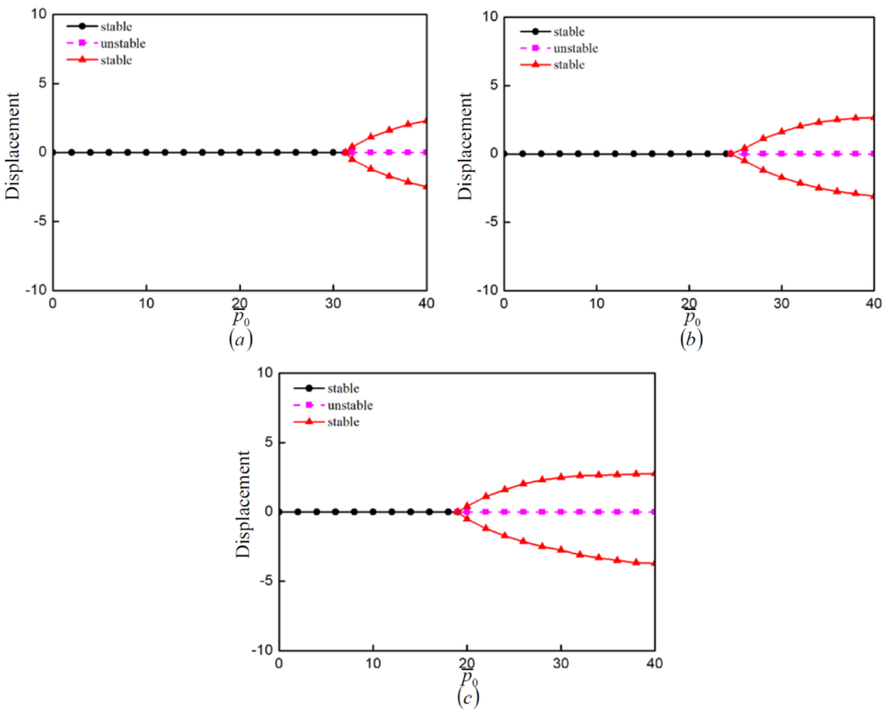
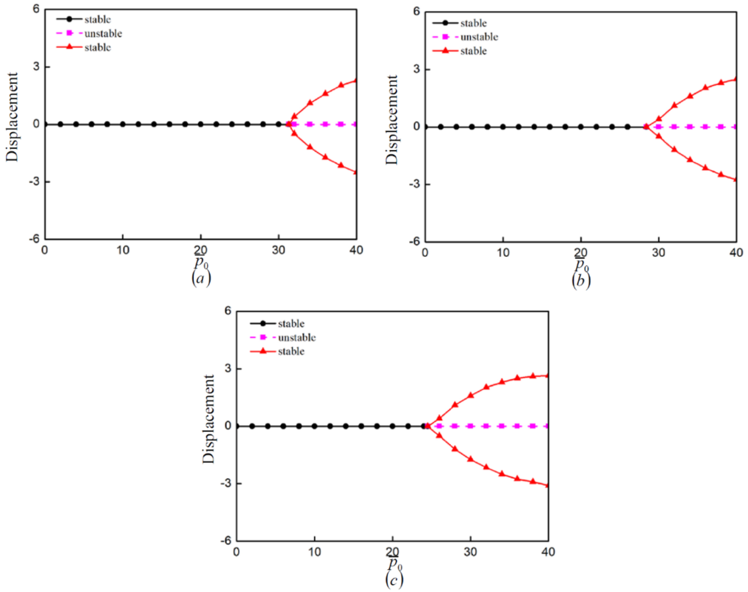
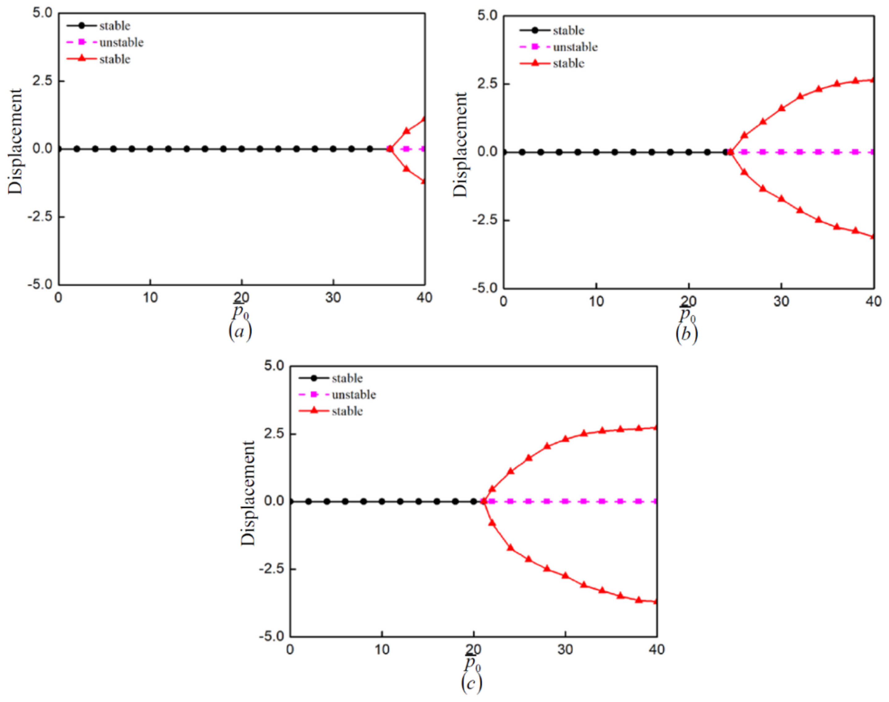
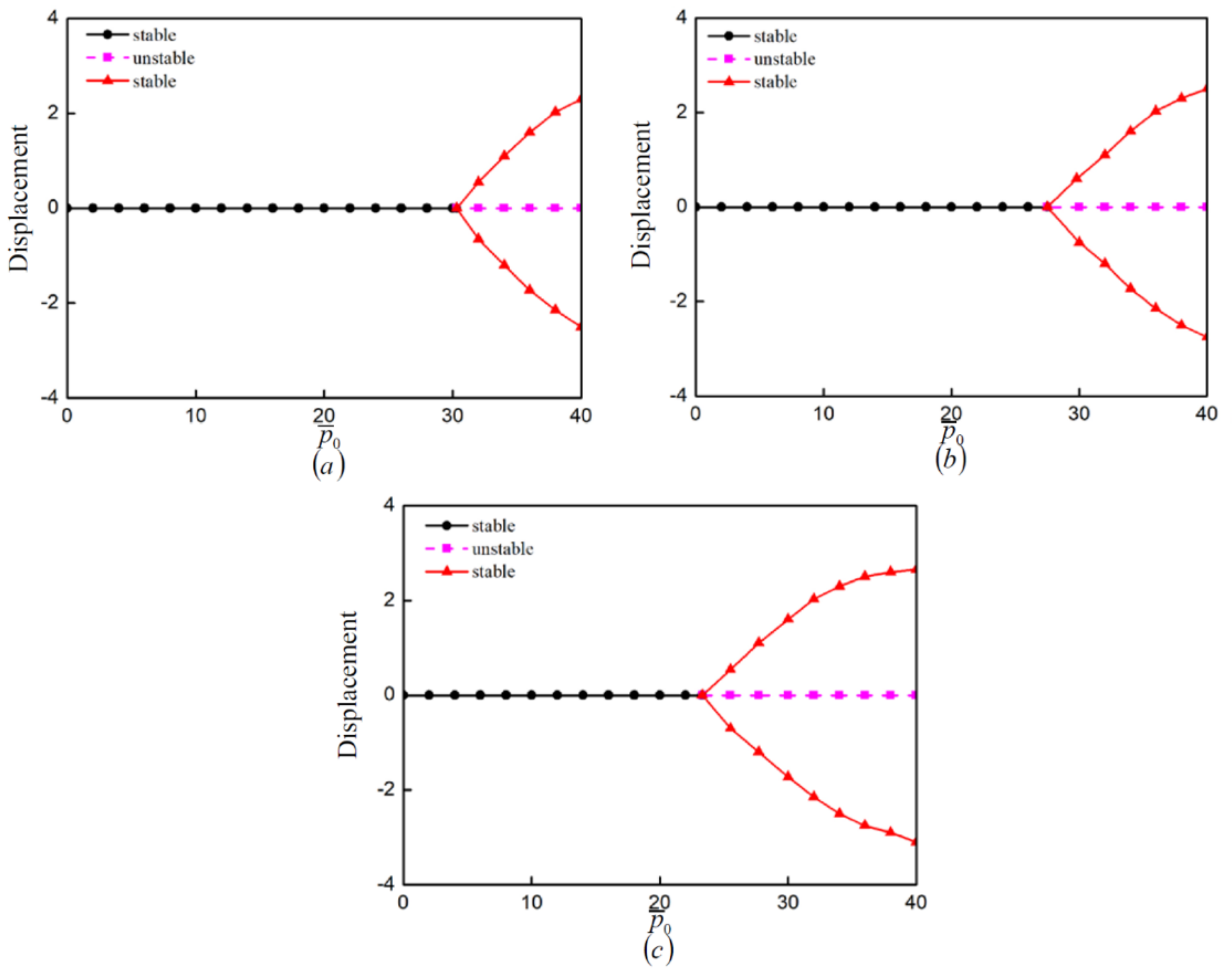
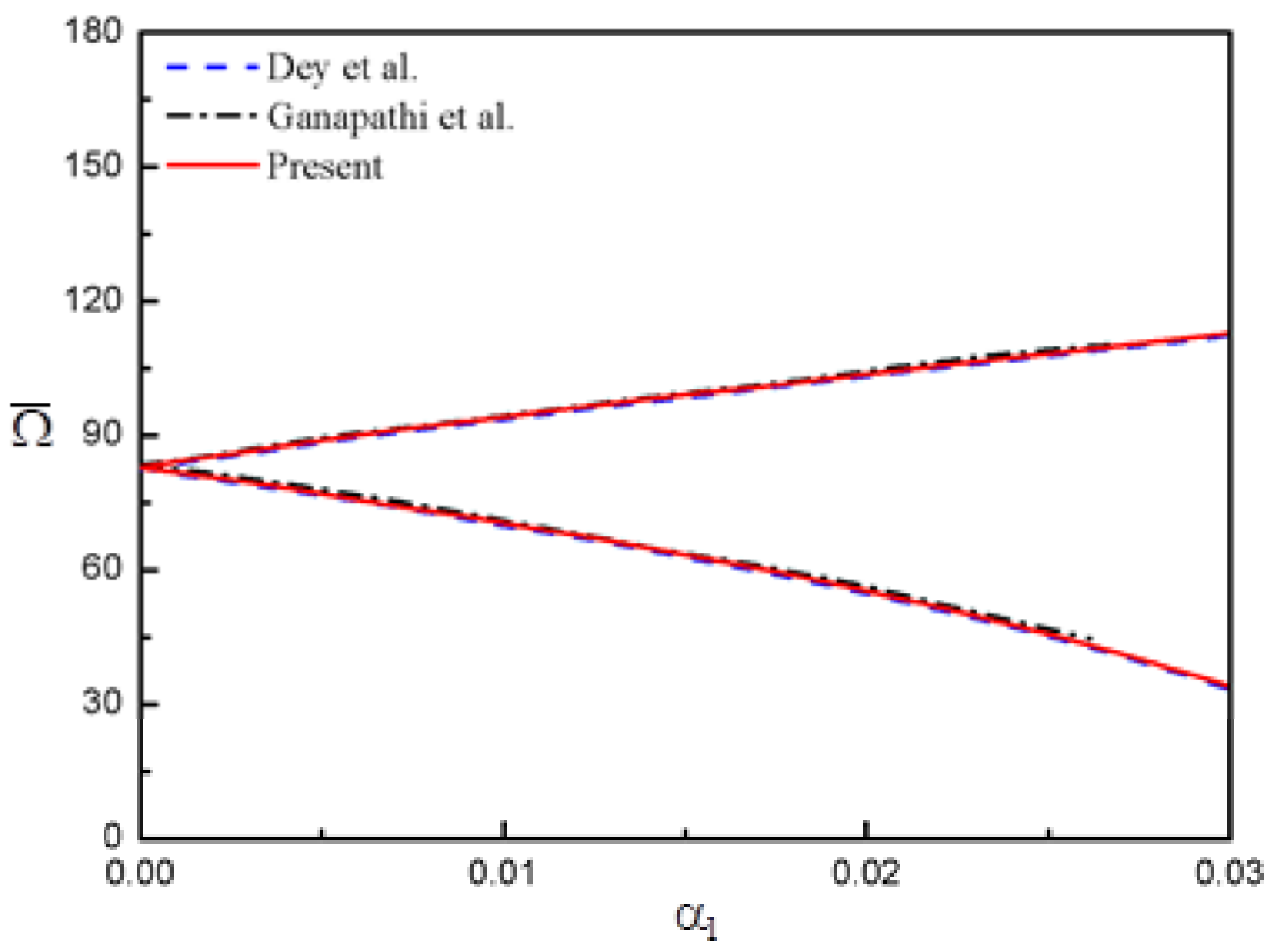
Bifurcation phenomena might occur when the static in-plane load is greater than the critical load.
(2)
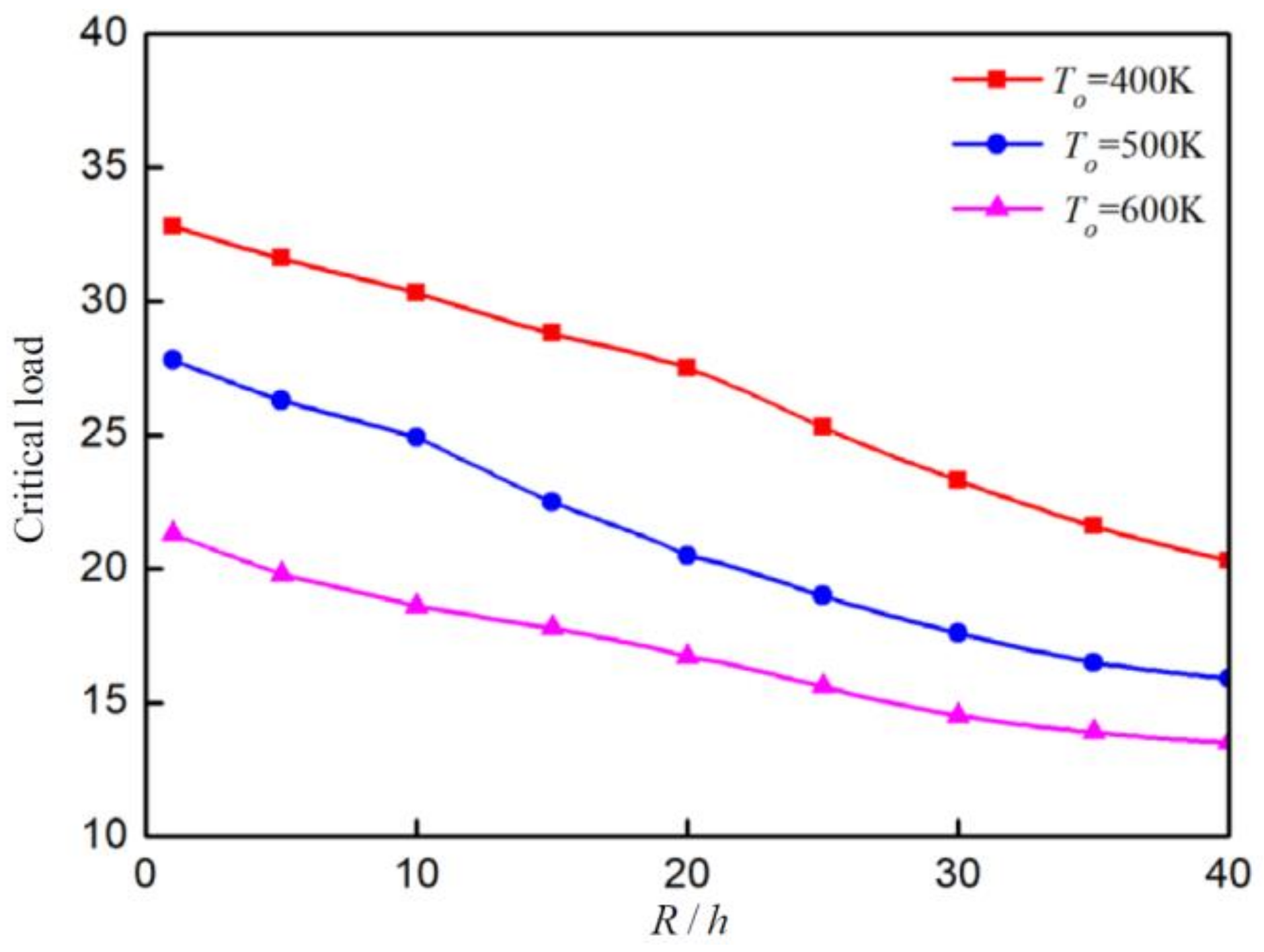
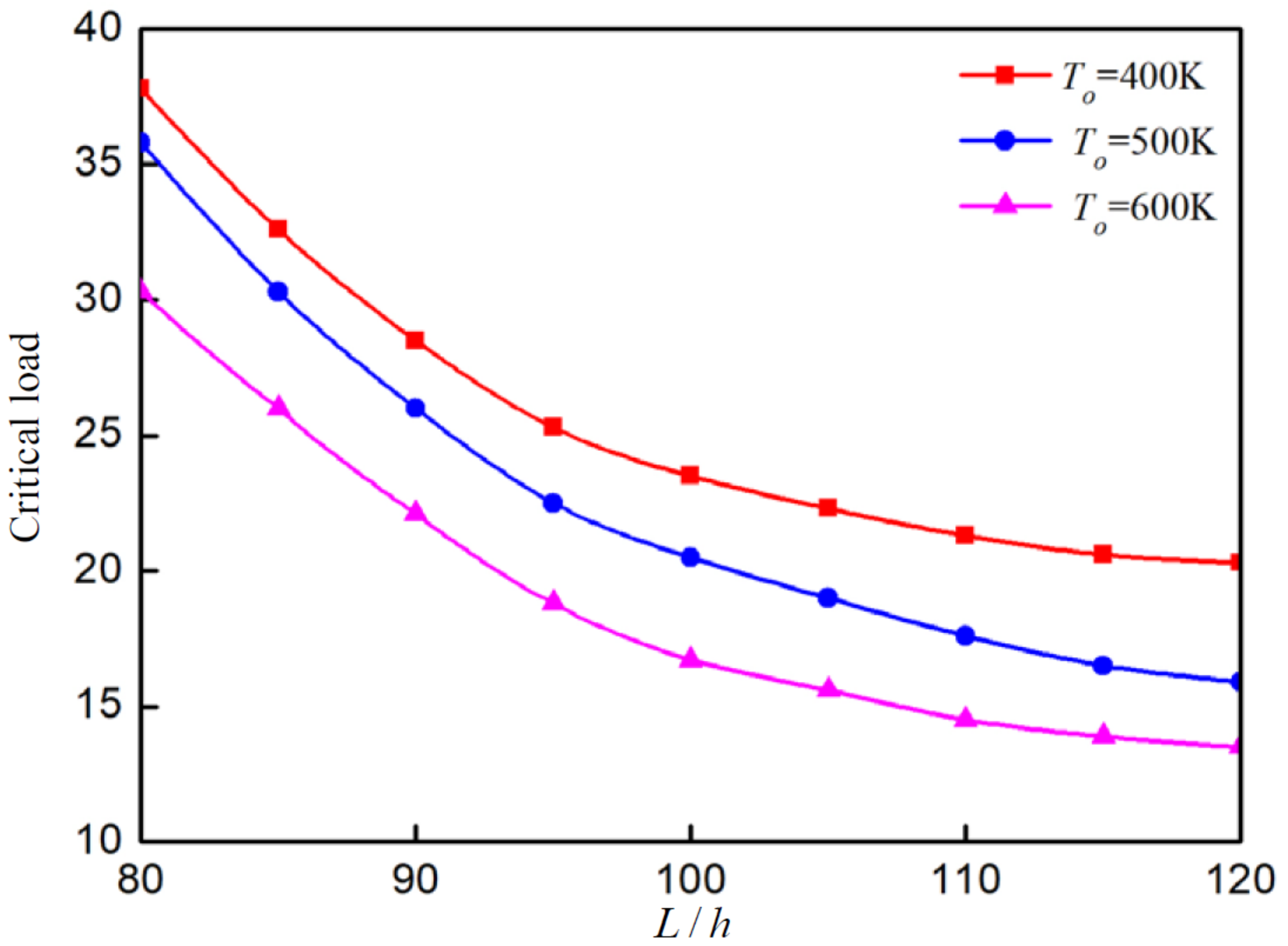
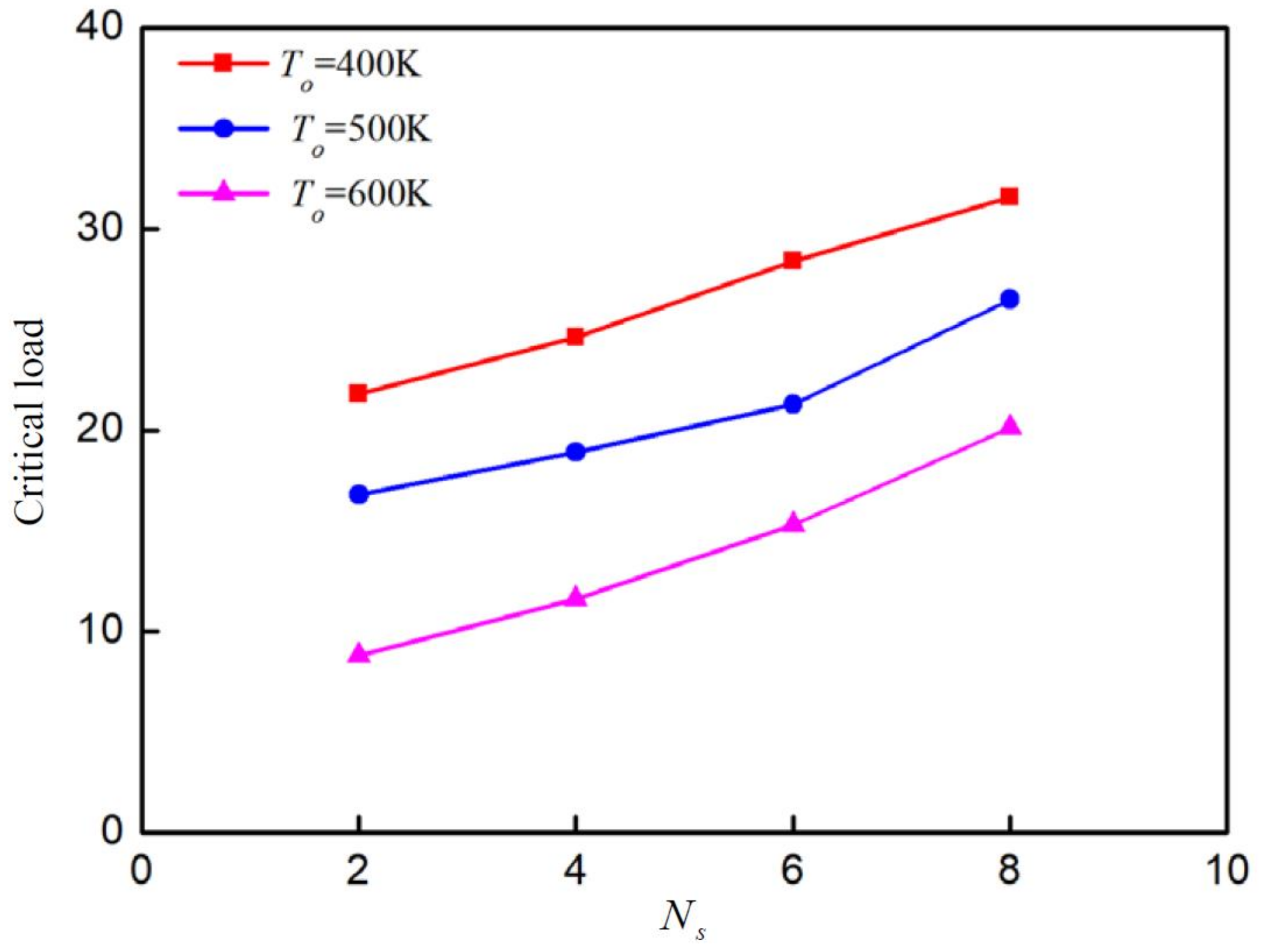
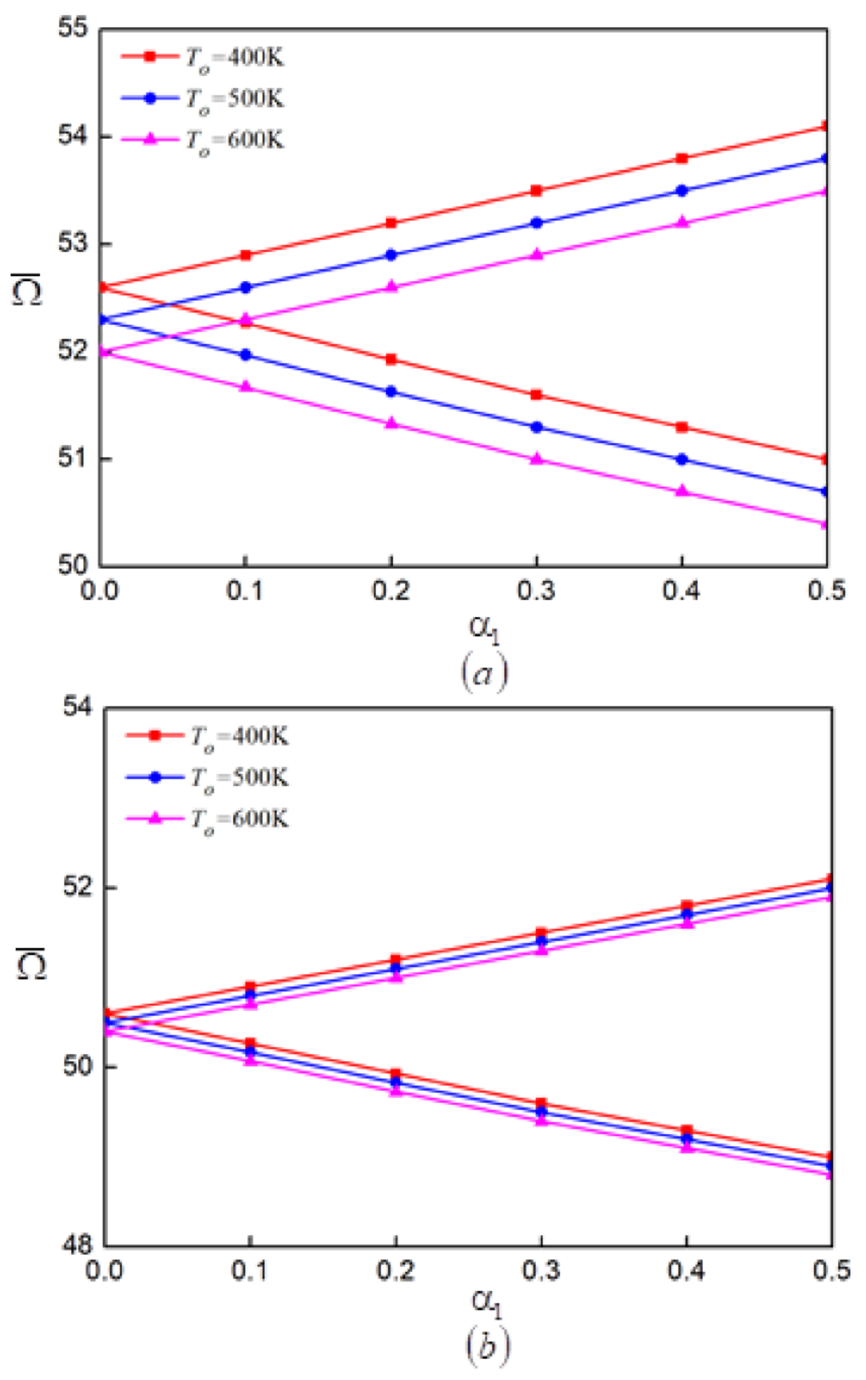
The ratio of radius to thickness, the ratio of length to thickness, the number of layers and the temperature field have significant effects on static bifurcation characteristics of a CFRP laminated cylindrical shell.
(3)
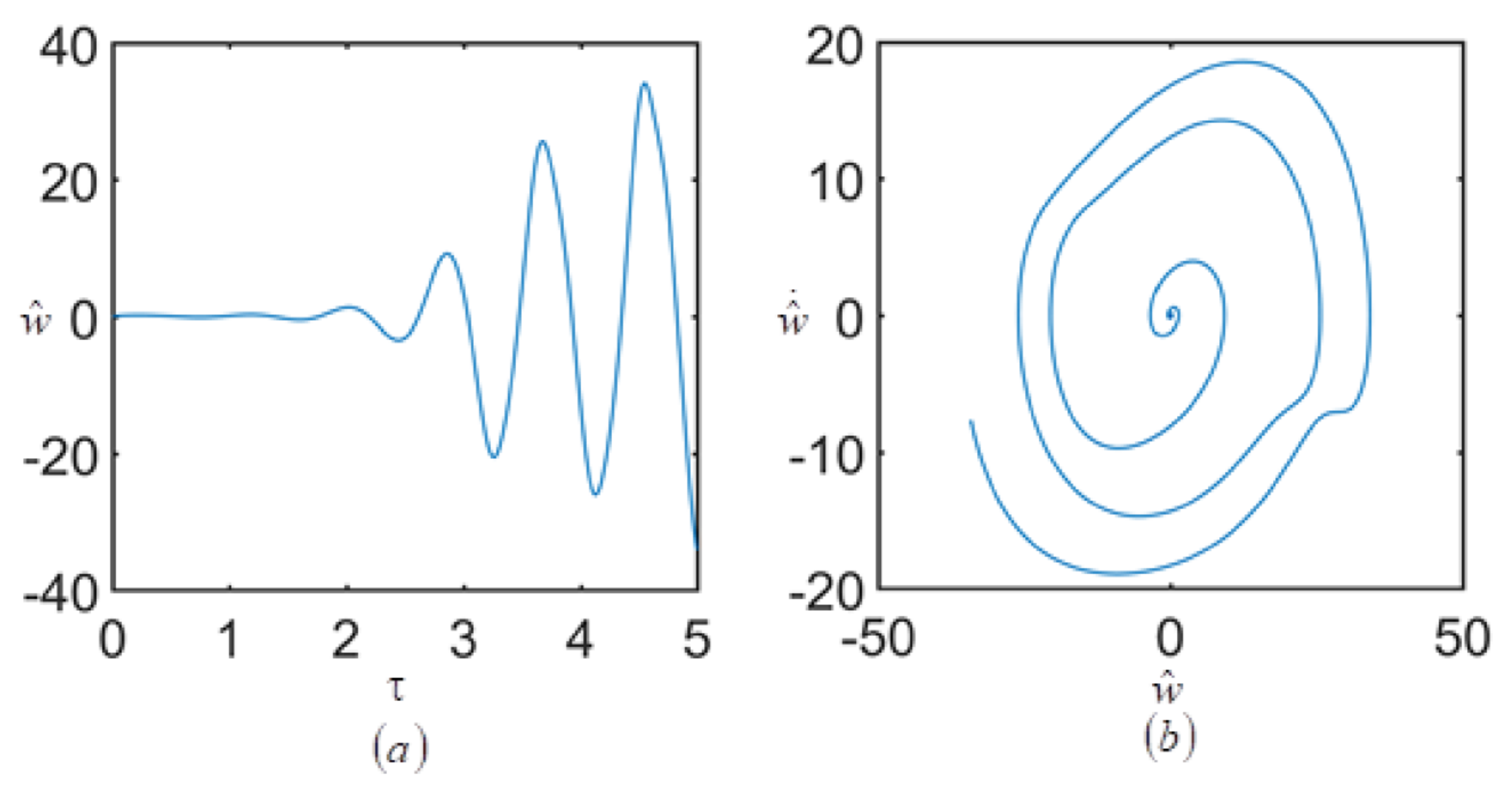
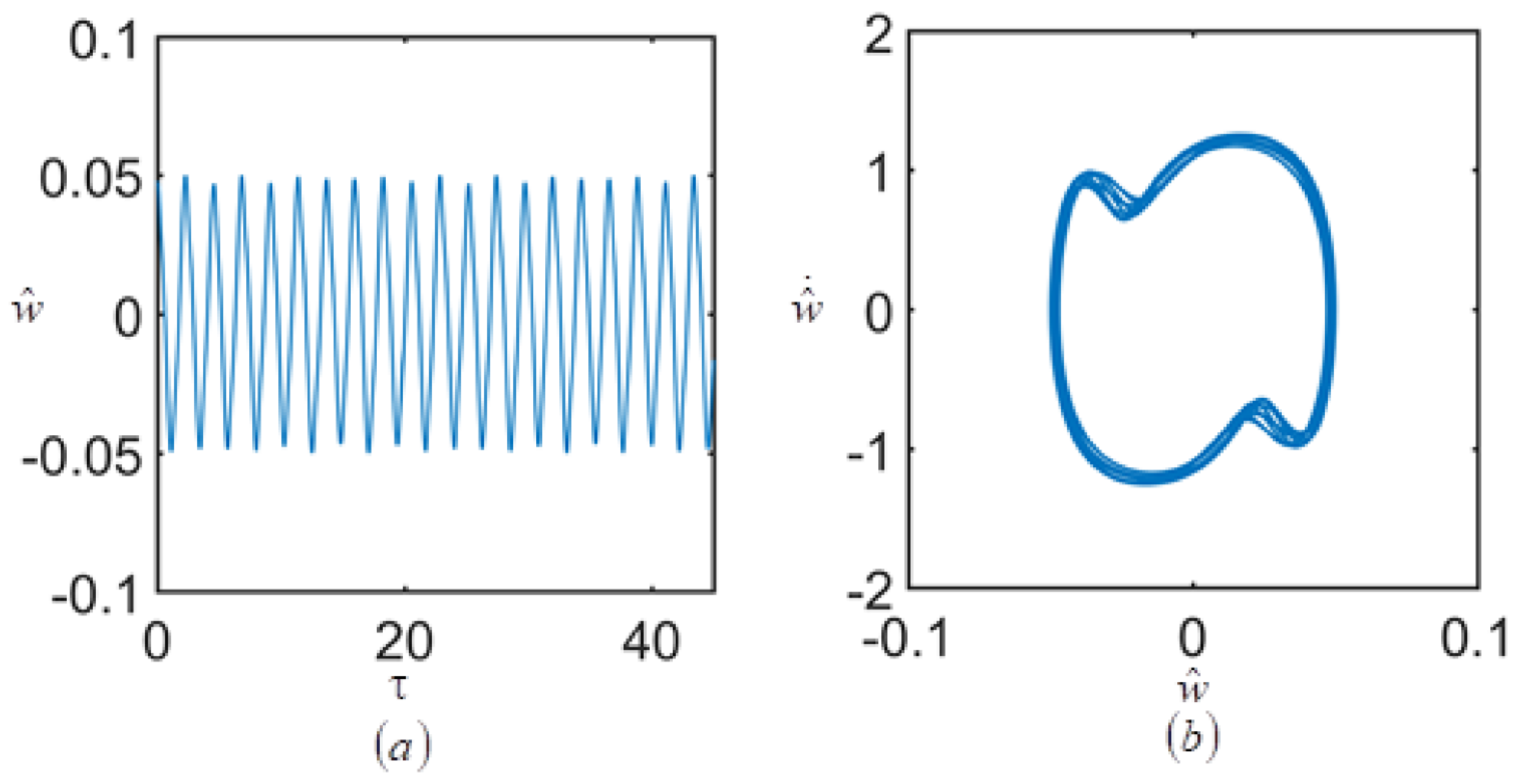
With an increase of ratio of radius to thickness, the ratio of length to thickness and the temperature field, the unstable regions in both modes are translated to a lower parametric excitation frequency.
(4)
When the number of layers decreases, the unstable regions of the system begin at a lower frequency.

Author Contributions

Conceptualization, S.Y. and W.Z.; methodology, Y.H.; software, L.L.; validation, S.Y. and W.M.; investigation, Y.H.; data curation, S.Y.; writing—original draft preparation, S.Y.; writing—review and editing, W.Z.; funding acquisition, S.Y., Y.H., W.Z. and W.M. All authors have read and agreed to the published version of the manuscript.

Funding

This research was funded by National Natural Science Foundation of China: 12002057, 11872127, 11832002 and 12102207; Scientific Research Project of Beijing Educational Committee: KM202111232023; Qin Xin Talents Cultivation Program, Beijing Information Science & Technology University: QXTCP C202102.

Institutional Review Board Statement

Not applicable.

Informed Consent Statement

Not applicable.

Acknowledgments

The authors gratefully acknowledge the supports of National Natural Science Foundation of China (NNSFC) through grant Nos. 12002057, 11872127, 11832002 and 12102207, Scientific Research Project of Beijing Educational Committee No. KM202111232023, Qin Xin Talents Cultivation Program, Beijing Information Science & Technology University QXTCP C202102.

Conflicts of Interest

The authors declare that they have no known competing financial interests or personal relationships that could have appeared to influence the work reported in this paper.

Appendix A

The coefficients obtained in Equations (42) and (43) are presented as follows
m 1 = e 5 e 4 ,   m 9 = e 2 e 4 ,   m 10 = e 1 e 4 ,   μ 1 = e 3 e 4 ,   n 1 = g 5 g 4 ,   n 9 = g 2 g 4 ,   n 10 = g 1 g 4 ,   μ 2 = g 3 g 4 , m 2 = a 1 b 3 e 10 e 4 Γ + a 3 b 1 e 10 e 4 Γ + a 2 b 3 e 9 e 4 Γ a 3 b 2 e 10 e 4 Γ + a 1 b 2 d 3 e 10 d 2 e 4 Γ + a 1 b 3 d 1 e 12 d 2 e 4 Γ + a 2 b 1 d 3 e 12 d 2 e 4 Γ a 3 b 1 d 1 e 12 d 2 e 4 Γ a 1 b 2 c 3 e 11 c 2 e 4 Γ + a 2 b 1 c 3 e 11 c 2 e 4 Γ a 2 b 3 c 1 e 11 c 2 e 4 Γ + a 3 b 2 c 1 e 11 c 2 e 4 Γ + e 6 e 4 , m 3 = + a 4 b 1 e 10 e 4 Γ + a 2 b 3 e 13 e 4 Γ a 3 b 2 e 13 e 4 Γ a 1 b 3 e 14 e 4 Γ + a 3 b 1 e 14 e 4 Γ a 4 b 2 e 9 e 4 Γ + a 2 b 1 c 4 e 11 c 2 e 4 Γ a 1 b 2 c 4 e 11 c 2 e 4 Γ a 4 b 1 d 4 e 12 d 2 e 4 Γ a 1 b 2 d 3 e 16 d 2 e 4 Γ + a 1 b 3 d 1 e 16 d 2 e 4 Γ + a 2 b 1 d 3 e 16 d 2 e 4 Γ + a 3 b 2 c 1 e 15 c 2 e 4 Γ a 1 b 2 c 3 e 15 c 2 e 4 Γ + a 2 b 1 c 3 e 15 c 2 e 4 Γ a 2 b 3 c 1 e 15 c 2 e 4 Γ + a 4 b 2 c 1 e 11 c 2 e 4 Γ a 3 b 1 d 1 e 16 d 2 e 4 Γ + e 7 e 4 , m 4 = a 4 b 2 e 13 e 4 Γ + a 4 b 1 e 14 e 4 Γ a 4 b 4 d 4 e 16 d 2 e 4 Γ a 1 b 2 c 4 e 15 c 2 e 4 Γ + a 2 b 1 c 4 e 15 c 2 e 4 Γ + a 4 b 2 c 1 e 15 c 2 e 4 Γ + e 8 e 4 , m 5 = a 1 b 4 e 10 e 4 Γ + a 5 b 1 e 10 e 4 Γ + a 2 b 4 e 9 e 4 Γ a 5 b 2 e 9 e 4 Γ a 1 b 2 c 5 e 11 c 2 e 4 Γ + a 2 b 1 c 5 e 11 c 2 e 4 Γ a 2 b 4 c 1 e 11 c 2 e 4 Γ + a 5 b 2 c 1 e 11 c 2 e 4 Γ a 1 b 2 d 4 e 12 d 2 e 4 Γ + a 1 b 4 d 1 e 12 d 2 e 4 Γ + a 2 b 1 d 4 e 12 d 2 e 4 Γ a 5 b 1 d 1 e 12 d 2 e 4 Γ + e 11 e 4 , m 6 = a 5 b 1 e 14 e 4 Γ + a 2 b 5 e 9 e 4 Γ a 6 b 2 e 9 e 4 Γ a 1 b 5 e 10 e 4 Γ + a 6 b 1 e 10 e 4 Γ + a 2 b 4 e 13 e 4 Γ a 5 b 2 e 13 e 4 Γ a 1 b 4 e 14 e 4 Γ + a 2 b 1 d 5 e 12 d 2 e 4 Γ a 6 b 1 d 1 e 12 d 2 e 4 Γ a 1 b 2 d 4 e 16 d 2 e 4 Γ + a 1 b 4 d 1 e 16 d 2 e 4 Γ + a 2 b 1 d 4 e 16 d 2 e 4 Γ + a 1 b 4 d 1 e 16 d 2 e 4 Γ + a 2 b 1 d 4 e 16 d 2 e 4 Γ a 5 b 1 d 1 e 16 d 2 e 4 Γ + a 2 b 1 c 6 e 11 c 2 e 4 Γ a 2 b 5 c 1 e 11 c 2 e 4 Γ + a 6 b 2 c 1 e 11 c 2 e 4 Γ a 1 b 2 c 5 e 15 c 2 e 4 Γ a 2 b 4 c 1 e 15 c 2 e 4 Γ + a 2 b 1 c 5 e 15 c 2 e 4 Γ a 1 b 2 c 6 e 11 c 2 e 4 Γ + a 5 b 2 c 1 e 15 c 2 e 4 Γ a 1 b 2 c 5 e 12 c 2 e 4 Γ + a 1 b 5 c 1 e 12 c 2 e 4 Γ + e 18 e 4 , m 7 = a 1 b 6 e 10 e 4 Γ + a 7 b 1 e 10 e 4 Γ + a 2 b 5 e 13 e 4 Γ a 6 b 2 e 13 e 4 Γ a 1 b 5 e 14 e 4 Γ + a 6 b 1 e 14 e 4 Γ + a 2 b 6 e 9 e 4 Γ a 7 b 2 e 9 e 4 Γ a 1 b 2 d 5 e 16 d 2 e 4 Γ + a 1 b 5 d 1 e 16 d 2 e 4 Γ + a 2 b 1 d 5 e 16 d 2 e 4 Γ a 6 b 1 d 1 e 16 d 2 e 4 Γ + a 6 b 2 c 1 e 15 c 2 e 4 Γ + a 7 b 2 c 1 e 11 c 2 e 4 Γ + a 2 b 1 c 6 e 15 c 2 e 4 Γ a 2 b 5 c 1 e 15 c 2 e 4 Γ a 2 b 6 c 1 e 11 c 2 e 4 Γ a 1 b 2 c 7 e 11 c 2 e 4 Γ + a 2 b 1 c 7 e 11 c 2 e 4 Γ a 1 b 2 c 6 e 15 c 2 e 4 Γ a 1 b 2 c 6 e 12 c 2 e 4 Γ + a 1 b 6 c 1 e 12 c 2 e 4 Γ + a 2 b 1 c 6 e 12 c 2 e 4 Γ a 7 b 1 c 1 e 12 c 2 e 4 Γ + e 19 e 4 , m 8 = a 2 b 6 e 13 e 4 Γ + a 7 b 2 e 13 e 4 Γ + a 1 b 6 e 14 e 4 Γ a 7 b 1 e 14 e 4 Γ a 1 b 2 d 6 e 16 d 2 e 4 Γ + a 1 b 6 d 1 e 16 d 2 e 4 Γ + a 2 b 1 d 6 e 16 d 2 e 4 Γ a 7 b 1 d 1 e 16 d 2 e 4 Γ a 1 b 2 c 7 e 15 c 2 e 4 Γ + a 2 b 1 c 7 e 15 c 2 e 4 Γ a 2 b 6 c 1 e 15 c 2 e 4 Γ + a 7 b 2 c 1 e 15 c 2 e 4 Γ + e 20 e 4 , n 2 = + a 2 b 3 g 9 g 4 Γ a 3 b 2 g 9 g 4 Γ a 1 b 3 g 9 g 4 Γ + a 3 b 1 g 10 g 4 Γ + a 1 b 3 d 1 g 12 d 2 g 4 Γ + a 2 b 1 d 3 g 12 d 2 g 4 Γ a 3 b 1 d 1 g 12 d 2 g 4 Γ a 1 b 2 c 3 g 11 c 2 g 4 Γ + a 2 b 1 c 3 g 11 c 2 g 4 Γ a 2 b 3 c 1 g 11 c 2 g 4 Γ + a 3 b 2 c 1 g 11 c 2 g 4 Γ a 1 b 2 d 3 g 12 d 2 g 4 Γ + g 6 g 4 , n 3 = + a 2 b 3 g 13 g 4 Γ a 3 b 2 g 13 g 4 Γ a 1 b 3 g 14 g 4 Γ + a 3 b 1 g 14 g 4 Γ a 4 b 2 g 9 g 4 Γ + a 4 b 1 g 10 g 4 Γ a 1 b 2 c 4 g 11 c 2 g 4 Γ + a 1 b 2 c 3 g 15 c 2 g 4 Γ a 4 b 1 d 1 g 12 d 2 g 4 Γ a 1 b 2 d 3 g 16 d 2 g 4 Γ + a 1 b 3 d 1 g 16 d 2 g 4 Γ + a 2 b 1 d 3 g 16 d 2 g 4 Γ a 3 b 1 d 1 g 16 d 2 g 4 Γ + a 2 b 1 c 3 g 15 c 2 g 4 Γ + a 2 b 1 c 4 g 11 c 2 g 4 Γ + a 4 b 2 c 1 g 11 c 2 g 4 Γ a 2 b 3 c 1 g 15 c 2 g 4 Γ + a 3 b 2 c 1 g 15 c 2 g 4 Γ + g 7 g 4 , n 4 = a 4 b 2 g 13 g 4 Γ + a 4 b 1 g 14 g 4 Γ a 1 b 2 c 4 g 11 c 2 g 4 Γ + a 2 b 1 c 4 g 15 c 2 g 4 Γ + a 4 b 2 c 1 g 15 c 2 g 4 Γ a 4 b 1 d 1 g 11 d 2 g 4 Γ + g 8 g 4 , n 5 = + a 2 b 4 g 9 g 4 Γ a 5 b 2 g 9 g 4 Γ a 1 b 4 g 10 g 4 Γ + a 5 b 1 g 10 g 4 Γ + a 1 b 2 d 4 g 12 d 2 g 4 Γ + a 1 b 4 d 1 g 12 d 2 g 4 Γ + a 2 b 1 d 4 g 12 d 2 g 4 Γ a 5 b 1 d 1 g 12 d 2 g 4 Γ + a 1 b 2 c 5 g 11 c 2 g 4 Γ + a 2 b 1 c 5 g 11 c 2 g 4 Γ a 2 b 4 c 1 g 11 c 2 g 4 Γ + a 5 b 2 c 1 g 11 c 2 g 4 Γ + g 17 g 4 , n 6 = + a 2 b 4 g 13 g 4 Γ a 5 b 2 g 13 g 4 Γ a 1 b 4 g 14 g 4 Γ + a 5 b 1 g 14 g 4 Γ + a 2 b 5 g 9 g 4 Γ a 6 b 2 g 9 g 4 Γ a 1 b 5 g 10 g 4 Γ + a 6 b 1 g 10 g 4 Γ a 1 b 2 d 4 g 16 d 2 g 4 Γ + a 1 b 4 d 1 g 16 d 2 g 4 Γ + a 2 b 1 d 4 g 16 d 2 g 4 Γ a 5 b 1 d 1 g 16 d 2 g 4 Γ a 2 b 4 c 1 g 15 c 2 g 4 Γ a 2 b 5 c 1 g 11 c 2 g 4 Γ a 1 b 2 c 6 g 11 c 2 g 4 Γ + a 2 b 1 c 5 g 15 c 2 g 4 Γ + a 6 b 2 c 1 g 11 c 2 g 4 Γ + a 2 b 1 c 6 g 11 c 2 g 4 Γ a 1 b 2 c 5 g 15 c 2 g 4 Γ a 1 b 2 d 5 g 12 d 2 g 4 Γ + a 5 b 2 c 1 g 15 c 2 g 4 Γ + a 1 b 5 d 1 g 12 d 2 g 4 Γ + a 2 b 1 d 5 g 12 d 2 g 4 Γ a 6 b 1 d 1 g 12 d 2 g 4 Γ + g 18 g 4 , n 7 = + a 2 b 6 g 9 g 4 Γ a 7 b 2 g 9 g 4 Γ a 1 b 6 g 10 g 4 Γ + a 7 b 1 g 10 g 4 Γ + a 2 b 5 g 13 g 4 Γ a 6 b 2 g 13 g 4 Γ a 1 b 5 g 14 g 4 Γ + a 6 b 1 g 14 g 4 Γ a 2 b 5 c 1 g 15 c 2 g 4 Γ + a 2 b 1 c 7 g 11 c 2 g 4 Γ a 2 b 6 c 1 g 11 c 2 g 4 Γ + a 7 b 2 c 1 g 11 c 2 g 4 Γ + a 2 b 1 c 6 g 15 c 2 g 4 Γ + a 6 b 2 c 1 g 15 c 2 g 4 Γ a 1 b 2 c 6 g 15 c 2 g 4 Γ a 1 b 2 d 6 g 12 d 2 g 4 Γ a 1 b 2 c 7 g 11 c 2 g 4 Γ + a 1 b 6 d 1 g 12 d 2 g 4 Γ + a 2 b 1 d 6 g 12 d 2 g 4 Γ a 7 b 1 d 1 g 12 d 2 g 4 Γ a 1 b 2 d 5 g 16 d 2 g 4 Γ + a 1 b 5 d 1 g 16 d 2 g 4 Γ + a 2 b 1 d 5 g 16 d 2 g 4 Γ a 6 b 1 d 1 g 16 d 2 g 4 Γ + g 19 g 4 , n 8 = a 1 b 6 g 14 g 4 Γ + a 7 b 1 g 14 g 4 Γ + a 2 b 6 g 13 g 4 Γ a 7 b 2 g 13 g 4 Γ a 1 b 2 d 6 g 16 d 2 g 4 Γ + a 1 b 6 d 1 g 16 d 2 g 4 Γ + a 2 b 1 d 6 g 16 d 2 g 4 Γ a 7 b 1 d 1 g 16 d 2 g 4 Γ a 1 b 2 c 7 g 15 c 2 g 4 Γ + a 2 b 1 c 7 g 15 c 2 g 4 Γ a 2 b 6 c 1 g 15 c 2 g 4 Γ + a 7 b 2 c 1 g 15 c 2 g 4 Γ + g 20 g 4 ,
where
Γ = a 1 b 2 a 2 b 1 ,   a 1 = 31.00835726 A 11 / L 7.871121054 L A 66 / R 2 , a 2 = 21.19550611 A 16 / L 0.01374976696 L A 26 / R 2 , a 3 = 1.316898663 L A 26 / R 3 ,   a 4 = 0.05435034699 L A 26 / R 3 , a 5 = 629.3381897 A 11 / L 2 + 11.58524211 A 66 / R 2 11.58524380 A 12 / R 2 , a 6 = 3130.142027 A 11 / L 2 56.62296173 A 66 / R 2 + 95.01717950 A 12 / R 2 , a 7 = 1642.614350 A 11 / L 2 + 5.21998485 A 66 / R 2 47.79767774 A 12 / R 2 , b 1 = 0.5428190419 A 16 / L 0.01374966901 L A 26 / R 2 , b 2 = 144.4460509 A 66 / L 0.7841786683 L A 22 / R 2 3.136714672 K L A 44 / R 2 , b 3 = 0.1641087045 L A 22 / R 3 ,   b 4 = 58.03431294 A 26 / R 2 , b 5 = 118.4772154 A 16 / L 2 49.61690248 A 26 / R 2 , b 6 = 2185.537826 A 16 / L 2 + 171.2842070 A 26 / R 2 , c 1 = 31.00835726 B 11 / L 7.871121054 L B 66 / R 2 , c 2 = 3.141803460 L A 55 K 31.00835727 D 11 / L 7.871121053 L D 66 / R 2 , c 3 = 1.316898663 L B 26 / R 3 ,   c 4 = 0.05435034702 L B 26 / R 3 , c 5 = 629.3381897 B 11 / L 2 + 11.58524211 B 66 / R 2 11.58524380 B 12 / R 2 , c 6 = 3130.142024 B 11 / L 2 56.62296171 B 66 / R 2 + 95.01717948 B 12 / R 2 , c 7 = 1642.614350 B 11 / L 2 + 5.21998492 B 66 / R 2 47.79767769 B 12 R 2 , d 1 = 144.4460509 B 66 / L 0.7841786683 L B 22 / R 2 3.136714672 K L B 44 / R 2 , d 2 = 0.5428190419 B 16 / L 0.01374966901 L B 26 / R 2 , d 3 = 0.1641087045 L B 22 / R 3 ,   d 4 = 58.03431294 B 26 / R 2 , d 5 = 118.4772154 B 16 / L 2 49.61690248 B 26 / R 2 , d 6 = 2185.537826 B 16 / L 2 + 171.2842070 B 26 / R 2 ,   e 1 = 25.09540907 , e 2 = 288.9114871 / L ,   e 3 = 6.273850301 L γ ,   e 4 = 6.273850303 L I 0 , e 5 = 288.9114871 A 55 K / L 6.273850307 L A 22 / R 2 15.71779897 L A 44 K / R 2 288.9114871 N x x T / L 15.71779897 L N θ θ T / R 2 , e 6 = 39.72963636 A 26 / R 3 ,   e 7 = 165.6765179 A 26 / R 3 ,   e 8 = 103.2852305 A 26 / R 3 , e 9 = 545.8105948 A 11 / L 2 6.64989922 A 66 / R 2 + 6.649896554 A 12 / R 2 , e 10 = 58.03431074 A 26 / R 2 ,   e 12 = 58.03431074 B 26 / R 2 , e 11 = 545.8105948 B 11 / L 2 6.64989922 B 66 / R 2 + 6.649896554 B 12 / R 2 , e 13 = 182.5445517 A 11 / L 2 143.4703132 A 66 / R 2 8.169858374 A 12 / R 2 , e 14 = 640.3323995 A 16 / L 2 + 17.60816090 A 26 / R 2 , e 15 = 182.5445517 B 11 / L 2 143.4703132 B 66 / R 2 8.169858374 B 12 / R 2 , e 16 = 640.3323995 B 16 / L 2 + 17.60816090 B 26 / R 2 , e 17 = 18183.70969 A 11 / L 3 18.0373938 L A 22 / R 4 + 197.449892 A 12 + 394.89978 A 66 / L R 2 , e 18 = 1209.128345 A 11 / L 3 + 5.069883616 L A 22 / R 4 242.5993347 A 12 + 485.19867 A 66 L R 2 , e 19 = 74011.22204 A 11 / L 3 59.75908863 L A 22 / R 4 356.845848 A 12 + 2841.38288 A 66 / L R 2 , e 20 = 9504.768786 A 11 / L 3 + 1.592447035 L A 22 / R 4 21.736372 A 12 + 43.4727439 A 66 / L R 2 , g 1 = 25.0954091 ,   g 2 = 1078.441452 / L ,   g 3 = 6.285173437 L γ ,   g 4 = 6.285173437 L I 0 , g 5 = 1078.441451 A 55 K / 6.285173436 L A 22 / R 2 42.00198451 L A 44 K / R 2 1078.441451 N x x T / L 42.00198451 L N θ θ T / R 2 , g 6 = 49.75797336 A 26 / R 3 ,   g 7 = 165.6765179 A 26 / R 3 ,   g 8 = 62.58299370 A 26 / R 3 , g 9 = 182.5480497 A 11 / L 2 27.31625097 A 66 / R 2 + 8.169718595 A 12 / R 2 , g 10 = 120.4374000 A 26 / R 2 ,   g 12 = 120.4374000 B 26 / R 2 , g 11 = 182.5480497 B 11 / L 2 27.31625097 B 66 / R 2 + 8.169718595 B 12 / R 2 , g 13 = 1188.606609 A 11 / L 2 3.31779223 A 66 / R 2 + 30.35534344 A 12 / R 2 , g 14 = 1536.656782 A 16 / L 2 120.4374000 A 26 / R 2 , g 15 = 1188.606609 B 11 / L 2 3.31779223 B 66 / R 2 + 30.35534344 B 12 / R 2 , g 16 = 1536.656782 B 16 / L 2 120.4374000 B 26 / R 2 , g 17 = 180.6408093 A 11 / L 3 + 1.690008865 L A 22 / R 4 33.432213 A 12 + 66.864426 A 66 / L R 2 , g 18 = 14810.2121 A 11 / L 3 59.7583037 L A 22 / R 4 1241.088955 A 12 + 2482.1779 A 66 / L R 2 , g 19 = 1585.526437 A 11 / L 3 + 4.777494122 L A 22 / R 4 291.12256 A 12 + 581.5127135 A 66 / L R 2 , g 20 = 23540.79961 A 11 / L 3 119.1995 L A 22 / R 4 119.3011 A 12 + 238.60223 A 66 / L R 2

References

  1. Montesano, J.; Bougherara, H.; Fawaz, Z. Application of infrared thermography for the characterization of damage in braided carbon fiber reinforced polymer matrix composites. Compos. Part B Eng. 2014, 60, 137–143. [Google Scholar] [CrossRef]
  2. Zhu, J.H.; Wei, L.; Wang, Z.; Liang, C.K.; Fang, Y. Application of carbon fiber reinforced polymer anode in electrochemical chloride extraction of steel-reinforced concrete. Constr. Build. Mater. 2016, 120, 275–283. [Google Scholar] [CrossRef]
  3. Zhu, J.H.; Zhu, M.; Han, N.; Liu, W.; Xing, F. Electrical and Mechanical Performance of Carbon Fiber-Reinforced Polymer Used as the Impressed Current Anode Material. Materials 2014, 7, 5438–5453. [Google Scholar] [CrossRef] [PubMed] [Green Version]
  4. Asadi, H.; Wang, Q. Dynamic stability analysis of a pressurized FG-CNTRC cylindrical shell interacting with supersonic airflow. Compos. Part B Eng. 2017, 118, 15–25. [Google Scholar] [CrossRef]
  5. Zhang, W.; Yang, S.W.; Mao, J.J. Nonlinear radial breathing vibrations of CFRP laminated cylindrical shell with non-normal boundary conditions subjected to axial pressure and radial line load at two ends. Compos. Struct. 2018, 190, 52–78. [Google Scholar] [CrossRef]
  6. Yang, S.W.; Zhang, W.; Mao, J.J. Nonlinear vibrations of carbon fiber reinforced polymer laminated cylindrical shell under non-normal boundary conditions with 1:2 internal resonance. Eur. J. Mech./A Solids 2019, 74, 317–336. [Google Scholar] [CrossRef]
  7. Kiral, B.G.; Kiral, Z.; Ozturk, H. Stability analysis of delaminated composite beams. Compos. Struct. 2015, 93, 342–350. [Google Scholar]
  8. Ke, L.L.; Wang, Y.S. Size effect on dynamic stability of functionally graded microbeams based on a modified couple stress theory. Compos. Struct. 2011, 79, 406–418. [Google Scholar] [CrossRef]
  9. Couto, C.; Maia, E.; Real, P.V.; Lopes, N. The effect of non-uniform bending on the lateral stability of steel beams with slender cross-section at elevated temperatures. Eng. Struct. 2018, 163, 153–166. [Google Scholar] [CrossRef]
  10. Talebitooti, M. Analytical and finite-element solutions for the buckling of composite sandwich conical shell with clamped ends under external pressure. Arch. Appl. Mech. 2017, 87, 59–73. [Google Scholar] [CrossRef]
  11. Maali, M.; Showkati, H.; Fatemi, S.M. Investigation of the buckling behavior of conical shells under weld-induced imperfections. Thin-Walled Struct. 2012, 57, 13–24. [Google Scholar] [CrossRef]
  12. Bich, D.H.; Phuong, N.T.; Tung, H.V. Buckling of functionally graded conical panels under mechanical loads. Compos. Struct. 2012, 94, 1379–1384. [Google Scholar] [CrossRef]
  13. Gajdzicki, M.; Perlinski, W.; Michalak, B. Stability analysis of bi-directionally corrugated steel plates with orthotropic plate model. Eng. Struct. 2018, 160, 519–534. [Google Scholar] [CrossRef]
  14. Zeng, H.C.; Huang, C.S.; Leissa, A.W.; Chang, M.J. Vibrations and stability of a loaded side-cracked rectangular plate via the MLS-Ritz method. Thin-Walled Struct. 2016, 106, 459–470. [Google Scholar] [CrossRef]
  15. Dey, T.; Ramachandra, L.S. Static and dynamic unstable analysis of composite cylindrical shell panels subjected to partial edge loading. Int. J. Non-Linear Mech. 2014, 64, 46–56. [Google Scholar] [CrossRef]
  16. Han, Q.K.; Qin, Z.Y.; Lu, W.X.; Chu, F.L. Dynamic stability analysis of periodic axial loaded cylindrical shell with time-dependent rotating speeds. Nonlinear Dyn. 2015, 81, 1649–1664. [Google Scholar] [CrossRef]
  17. Kolanua, N.R.; Rajub, G.; Ramji, M. Experimental and numerical studies on the buckling and post-buckling behavior of single blade-stiffened CFRP panels. Compos. Struct. 2018, 196, 135–154. [Google Scholar] [CrossRef]
  18. Salvetti, M.; Gilioli, A.; Sbarufatti, C.; Manes, A.; Giglio, M. Analytical model of the dynamic behaviour of CFRP plates subjected to low velocity impacts. Compos. Part B Eng. 2018, 142, 47–55. [Google Scholar] [CrossRef]
  19. Cui, J.; Dong, D.; Zhang, X.; Huang, X.; Lu, G. Influence of thickness of composite layers on failure behaviors of carbon fiber reinforced plastics/aluminum alloy electromagnetic riveted lap joints under high-speed loading. Int. J. Impact Eng. 2018, 115, 1–9. [Google Scholar] [CrossRef]
  20. Zhang, F.S.; Xu, J.Z.; Xu, G.D.; Zu, L. The buckling behavior of radome with different braided angles based on CFRP. Compos. Struct. 2017, 176, 597–607. [Google Scholar] [CrossRef]
  21. Juntanalikit, P.; Jirawattanasomkul, T.; Pimanmas, A. Experimental and numerical study of strengthening non-ductile RC columns with and without lap splice by Carbon Fiber Reinforced Polymer (CFRP) jacketing. Eng. Struct. 2016, 125, 400–418. [Google Scholar] [CrossRef]
  22. Reuter, C.; Sauerland, K.H.; Tröster, T. Experimental and numerical crushing analysis of circular CFRP tubes under axial impact loading. Compos. Struct. 2017, 174, 33–44. [Google Scholar] [CrossRef]
  23. Timme, S.; Trappe, V.; Korzen, M.; Schartel, B. Fire stability of carbon fiber reinforced polymer shells on the intermediate-scale. Compos. Struct. 2017, 178, 320–329. [Google Scholar] [CrossRef]
  24. Zhang, W.; Zhao, M.H. Nonlinear vibrations of a composite laminated cantilever rectangular plate with one-to-one internal resonance. Nonlinear Dyn. 2012, 70, 295–313. [Google Scholar] [CrossRef]
  25. Zhao, M.H.; Zhang, W. Nonlinear dynamics of composite laminated cantilever rectangular plate subject to third-order piston aerodynamics. Acta Mech. 2014, 225, 1985–2004. [Google Scholar] [CrossRef]
  26. Zhang, W.; Zhao, M.H.; Guo, X.Y. Nonlinear responses of a symmetric cross-ply composite laminated cantilever rectangular plate under in-plane and moment excitations. Compos. Struct. 2013, 100, 554–565. [Google Scholar] [CrossRef]
  27. Hwu, C.; Hsu, H.W.; Lin, Y.H. Free vibration of composite sandwich plates and cylindrical shells. Compos. Struct. 2017, 171, 528–537. [Google Scholar] [CrossRef]
  28. Viswanathan, K.; Javed, S. Free vibration of anti-symmetric angle-ply cylindrical shell walls using first-order shear deformation theory. J. Vib. Control 2016, 22, 1757–1768. [Google Scholar] [CrossRef]
  29. Sarkheil, S.; Foumani, M.S. Free vibrational characteristics of rotating joined cylindrical-conical shells. Thin-Walled Struct. 2016, 107, 657–670. [Google Scholar] [CrossRef]
  30. Amabili, M.; Balasubramanian, P.; Ferrari, G. Travelling wave and non-stationary response in nonlinear vibrations of water-filled circular cylindrical shells: Experiments and simulations. J. Sound Vib. 2016, 381, 220–245. [Google Scholar] [CrossRef]
  31. Song, Z.G.; Zhang, L.W.; Liew, K.M. Vibration analysis of CNT-reinforced functionally graded composite cylindrical shells in thermal environments. Int. J. Mech. Sci. 2016, 115–116, 339–347. [Google Scholar] [CrossRef]
  32. Zhang, W.; Hao, Y.X.; Yang, J. Nonlinear dynamics of FGM circular cylindrical shell with clamped-clamped edges. Compos. Struct. 2012, 94, 1075–1086. [Google Scholar] [CrossRef]
  33. Du, C.C.; Li, Y.H. Nonlinear resonance behavior of functionally graded cylindrical shells in thermal environments. Compos. Struct. 2013, 102, 164–174. [Google Scholar] [CrossRef]
  34. Sun, Y.; Zhang, W.; Yao, M.H. Multi-pulse chaotic dynamics of circular mesh antenna with 1:2 internal resonance. Int. J. Appl. Mech. 2017, 9, 1750060. [Google Scholar] [CrossRef]
  35. Liu, T.; Zhang, W.; Wang, J.F. Nonlinear dynamics of composite laminated circular cylindrical shell clamped along a generatrix and with membranes at both ends. Nonlinear Dyn. 2017, 90, 1393–1417. [Google Scholar] [CrossRef]
  36. Wang, Y.Q. Nonlinear vibration of a rotating laminated composite circular cylindrical shell: Traveling wave vibration. Nonlinear Dyn. 2014, 77, 1693–1707. [Google Scholar] [CrossRef]
  37. Hao, Y.X.; Yang, S.W.; Zhang, W.; Yao, M.H.; Wang, A.W. Flutter of high-dimension nonlinear system for a FGM truncated conical shell. Mech. Adv. Mater. Struct. 2018, 25, 47–61. [Google Scholar] [CrossRef]
  38. Wang, Y.Q.; Guo, X.H.; Chang, H.H.; Li, H.Y. Nonlinear dynamic response of rotating circular cylindrical shells with precession of vibrating shape, Part I: Numerical solution. Int. J. Mech. Sci. 2010, 52, 1217–1224. [Google Scholar] [CrossRef]
  39. Wang, Y.Q.; Guo, X.H.; Chang, H.H.; Li, H.Y. Nonlinear dynamic response of rotating circular cylindrical shells with precession of vibrating shape, Part II: Approximate analytical solution. Int. J. Mech. Sci. 2010, 52, 1208–1216. [Google Scholar] [CrossRef]
  40. Shen, H.S. Nonlinear vibration of shear deformable FGM cylindrical shells surrounded by an elastic medium. Compos. Struct. 2012, 94, 1144–1154. [Google Scholar] [CrossRef]
  41. Shen, H.S.; Wang, H. Nonlinear vibration of shear deformable FGM cylindrical panels resting on an elastic medium in thermal environments. Compos. Part B Eng. 2014, 60, 167–177. [Google Scholar] [CrossRef]
  42. Reddy, J.N. Mechanics of Laminated Composite Plates and Shells: Theory and Analysis; CRC Press: New York, NY, USA, 2004. [Google Scholar]
  43. Hao, Y.X.; Zhang, W.; Yang, L.; Wang, J.H. Dynamic Response of Cantilever FGM Cylindrical Shell. Appl. Mech. Mater. 2012, 130, 3986–3993. [Google Scholar] [CrossRef]
  44. Efraim, E.; Eisenberger, M. Exact vibration analysis of variable thickness thick annular isotropic and FGM plates. J. Sound Vib. 2007, 299, 720–738. [Google Scholar] [CrossRef]
  45. Noseir, A.; Reddy, J.N. A study of non-linear dynamic equations of higher-order deformation plate theories. Int. J. Non-Linear Mech. 1991, 26, 233–249. [Google Scholar] [CrossRef]
  46. Bhimaraddi, A. Large amplitude vibrations of imperfect antisymmetric angle-ply laminated plates. J. Sound Vib. 1993, 162, 457–470. [Google Scholar] [CrossRef]
  47. Zhang, X.M.; Liu, G.R.; Lam, K.Y. Vibration analysis of thin cylindrical shells using wave propagation approach. J. Sound Vib. 2001, 239, 397–403. [Google Scholar] [CrossRef]
  48. Song, Z.G.; Li, F.M. Aerothermoelastic analysis and active flutter control of supersonic composite laminated cylindrical shells. Compos. Struct. 2013, 106, 653–660. [Google Scholar] [CrossRef]
  49. Lee, D.S. Nonlinear dynamic buckling of orthotropic cylindrical shells subjected to rapidly applied loads. J. Eng. Math. 2000, 38, 141–154. [Google Scholar] [CrossRef]
  50. Gao, K.; Gao, W.; Wu, D.; Song, C. Nonlinear dynamic stability of the orthotropic functionally graded cylindrical shell surrounded by Winkler-Pasternak elastic foundation subjected to a linearly increasing load. J. Sound Vib. 2018, 415, 147–168. [Google Scholar] [CrossRef]
  51. Darabi, M.; Ganesan, R. Non-linear dynamic unstable analysis of laminated composite cylindrical shells subjected to periodic axial loads. Compos. Struct. 2016, 147, 168–184. [Google Scholar] [CrossRef]
  52. Lei, Z.X.; Zhang, L.W.; Liew, K.M.; Yu, J.L. Dynamic stability analysis of carbon nanotubereinforced functionally graded cylindrical panels using the element-free kp-Ritz method. Compos. Struct. 2014, 113, 328–338. [Google Scholar] [CrossRef]
  53. Ganapathi, M.; Balamurugan, V. Dynamic unstable analysis of laminated composite circular cylindrical shell. Comput. Struct. 1998, 69, 181–189. [Google Scholar] [CrossRef]
  54. Dey, T.; Ramachandra, L.S. Dynamic stability of simply supported composite cylindrical shells under partial axial loading. J. Sound Vib. 2015, 353, 272–291. [Google Scholar] [CrossRef]
Figure 1. Model of a CFRP laminated cylindrical shell: (a) the mechanical model, (b) the sections of x = L and x = 0 .
Mathematics 10 01531 g001
Figure 2. Critical in-plane load versus the ratio of radius to thickness R / h with different temperature fields.
Mathematics 10 01531 g002
Figure 3. Critical in-plane load versus the ratio of length to thickness L / h with different temperature fields.
Mathematics 10 01531 g003
Figure 4. Critical in-plane load versus the number of layers N s with different temperature fields.
Mathematics 10 01531 g004
Figure 5. The transverse deflection of the CFRP laminated cylindrical shell versus the static in-plane load with different temperature fields: (a) T o = 400   K , (b) T o = 500   K , (c) T o = 600   K .
Mathematics 10 01531 g005
Figure 6. The transverse deflection of the CFRP laminated cylindrical shell versus the static in-plane load with different numbers of layers N s : (a) N s = 8 , (b) N s = 6 , (c) N s = 4 .
Mathematics 10 01531 g006
Figure 7. The transverse deflection of the CFRP laminated cylindrical shell versus the static in-plane load with different ratios of length to thickness L / h : (a) L / h = 80 , (b) L / h = 100 , (c) L / h = 120 .
Mathematics 10 01531 g007
Figure 8. The transverse deflection of the CFRP laminated cylindrical shell versus the static in-plane load with different ratios of radius to thickness R / h : (a) R / h = 10 , (b) R / h = 20 , (c) R / h = 30 .
Mathematics 10 01531 g008
Figure 9. The dynamic unstable regions of a cross-ply laminated composite cylindrical shell ( L / R = 1 , R / h = 100 ) subjected to uniform periodic in-plane loading.
Mathematics 10 01531 g009
Figure 10. The dynamic unstable regions of the CFRP laminated cylindrical shell with different temperature fields: (a) first mode, and (b) second mode.
Mathematics 10 01531 g010
Figure 11. The linear response for the CFRP laminated cylindrical shell with an excitation frequency in the unstable region: (a) the time history on the plane ( τ ,   w ^ ) , and (b) the phase portrait on the plane ( w ^ ,   w ^ ˙ ) .
Mathematics 10 01531 g011
Figure 12. The nonlinear response for the CFRP laminated cylindrical shell with an excitation frequency in the unstable region: (a) the time history on the plane ( τ ,   w ^ ) , and (b) the phase portrait on the plane ( w ^ ,   w ^ ˙ ) .
Mathematics 10 01531 g012
Figure 13. The linear response for the CFRP laminated cylindrical shell with an excitation frequency in the stable region: (a) the time history on the plane ( τ ,   w ^ ) , and (b) the phase portrait on the plane ( w ^ ,   w ^ ˙ ) .
Mathematics 10 01531 g013
Figure 14. The nonlinear response for the CFRP laminated cylindrical shell with an excitation frequency in the stable region: (a) the time history on the plane ( τ ,   w ^ ) , and (b) the phase portrait on the plane ( w ^ ,   w ^ ˙ ) .
Mathematics 10 01531 g014
Figure 15. The dynamic unstable regions of the CFRP laminated cylindrical shell with different L / h : (a) the first mode, and (b) the second mode.
Mathematics 10 01531 g015
Figure 16. The dynamic unstable regions of the CFRP laminated cylindrical shell with different R / h : (a) the first mode, and (b) the second mode.
Mathematics 10 01531 g016
Figure 17. The dynamic unstable regions of the CFRP laminated cylindrical shell with different N s : (a) the first mode, and (b) the second mode.
Mathematics 10 01531 g017
Table 1. Comparison of the frequency parameters ( Ω n = ω n R ( 1 ν 2 ) ρ / E ) for a simply supported isotropic cylindrical shell with L / R = 20 , m = 1 and ν = 0.3 .
h / R n Zhang et al. [47]Song et al. [48]Present Study
0.0500.09295860.09293920.0929465
10.01610650.01612990.0151185
20.03930380.03932310.0393236
30.1098113 0.10976530.1096523
40.10981130.10976530.1098103
0.00200.09292960.09292960.0929236
10.01610110.01610110.01610032
20.00545320.00545360.0054532
30.00504180.00504240.0050423
40.00853400.00853440.0085354
Table 2. Comparison of a dimensionless axial static buckling load P c r L 2 / E 02 h 3 on a simply supported orthotropic cylindrical shell.
( m , n ) Lee et al. [49]Gao et al. [50]Present Study
(1, 1)78,139.7278,145.7378,151.26
(1, 2)29,556.7929,580.8329,578.52
(1, 3)13,850.6713,904.7513,895.28
(2, 1)32,341.2732,347.2832,343.52
(2, 2)19,852.9019,876.9319,856.36
(2, 3)12,046.7312,100.8212,089.65
Publisher’s Note: MDPI stays neutral with regard to jurisdictional claims in published maps and institutional affiliations.

