Article

Diffusion Mechanism of Slurry during Grouting in a Fractured Aquifer: A Case Study in Chensilou Coal Mine, China

1
State Key Laboratory of Geomechanics and Deep Underground Engineering, China University of Mining and Technology, Xuzhou 221116, China
2
School of Mines, China University of Mining and Technology, Xuzhou 221116, China
3
State Key Laboratory of Coal Resources and Safe Mining, China University of Mining and Technology, Xuzhou 221116, China
*
Author to whom correspondence should be addressed.
Mathematics 2022, 10(8), 1345; https://doi.org/10.3390/math10081345
Submission received: 9 March 2022 / Revised: 9 April 2022 / Accepted: 15 April 2022 / Published: 18 April 2022

Abstract

:
Grouting is one of the main technical means to prevent water inrush hazards in coal seam floor aquifers. It is of great significance to elucidate the diffusion law of slurry in the process of grouting in fractured aquifers for safe mining in coal mines. In this paper, the mechanism of slurry diffusion in horizontal fractures of fractured aquifers was studied based on the Bingham slurry with time-varying characteristics; additionally, a one-dimensional seepage grouting theoretical model considering the temporal and spatial variation of slurry viscosity under constant grouting rate was established. In this model, the grouting pressure required by the predetermined slurry diffusion radius can be obtained by knowing the grouting hole pressure and injection flow. Slurry properties, fracture parameters, grouting parameters, and water pressure were the parameters affecting the slurry diffusion process. Looking at the problem of water disaster prevention of coal seam floor in the Working Face 2509 of the Chensilou Coal Mine, according to the aquifer parameters and model calculation results, a grouting scheme with a slurry diffusion radius of 20 m and grouting pressure of 12 MPa was proposed. Finally, with the comparative analysis of the transient electromagnetic method (TEM) and water inflow before and after grouting, it was verified that the design grouting pressure and the spacing of grouting holes were reasonable and the grouting effect was good.

1. Introduction

With the exploitation of coal resource extending deeper in China, the threat of mine water disasters to coal mining safety is becoming more and more obvious [1,2,3,4,5]. In the mining process of a Carboniferous–Permian coal seam in a North China coal field, the working face is seriously threatened by a high pressure limestone aquifer [6,7] in the coal seam floor (Figure 1). As a kind of coal mine geological guarantee technology, grouting technology is often applied in mining to control for water disasters, and the analysis of slurry diffusion rules and grouting effects in grouting engineering are urgent and difficult problems [8,9,10,11].
At present, many scientific researchers have been conducting significant research on slurry diffusion rules, and fruitful research results have been achieved [12,13,14,15,16]. Grouting theory is the basis for the study of slurry diffusion rules, which can provide guidance for the design and implementation of grouting engineering [17,18,19,20,21,22]. The existing grouting theories mainly include pore rock mass grouting theory [23], fractured rock mass grouting theory [24], fracturing grouting theory [25], compaction grouting theory [26], and dynamic water grouting theory [27]. Theoretical analysis is an effective means to study the rules of slurry diffusion, in which the rule of slurry flow in a single fracture is the basis of the study of slurry diffusion rules.
Some scholars simulated the grout diffusion rule in hydrostatic and hydrodynamic conditions through artificial equipment, and put forward the flow equation of slurry in a single fracture [28,29,30,31]. A quasi-three-dimensional fracture grouting test system was developed for hydrodynamic conditions, the slurry diffusion rule was studied and the grouting plugging method of water inrush in fractured rock mass was put forward [32]. The grouting plugging mechanism of rock mass was studied by using a seepage grouting simulation test device with three-dimensional constant pressure [33].
The evaluation of grouting effect is an indispensable step in grouting engineering [34,35]. Liu et al., treated loess strata in the tunnel by curtain grouting and evaluated the grouting effect through ground penetrating radar (GPR) and numerical simulation method [36]. It was concluded that grouting can effectively block the inflow and seepage of groundwater, and effectively control disasters such as water and mud inflow in the heading face. Zhang et al., systematically classified the grouting effect evaluation methods and put forward the inspection methods and standards of various grouting technologies, which provided a reference for the grouting construction of similar projects [37]. In addition, many scholars studied the diffusion law of cement slurry in planar fractures by numerical simulation software and obtained the parameters such as diffusion radius and grouting pressure of slurry [8,9,38,39,40,41,42].
The above research mainly focused on grouting simulation experiments in the laboratory, nevertheless, most of the grouting projects for mine water disaster control are carried out in limestone or sandstone aquifers, and the parameters in the grouting process are often determined based on experience and lack of corresponding theoretical basis [43]. More importantly, as the most commonly used grouting in engineering, the viscosity of cement slurry is time-varying; that is, the viscosity tends to increase with time, and the slurry diffusion radius will be much smaller if time variability is considered. However, many grouting diffusion theories ignored this property, and the viscosity used in the establishment of the grouting diffusion model was fixed as the initial viscosity value [44]. The theoretical values used in the model were obviously much larger than the actual values, and the grouting hole distance designed was also unreasonable, which was difficult to ensure the grouting effect when used to guide the construction. In the light of existing problems, this paper aims to study the diffusion mechanism and grouting effect of slurry with time-dependent behavior of viscosity, and then provides guidance for the design and implementation of aquifer grouting engineering.

2. Methodology

2.1. Basic Assumptions of Slurry Flow Model

The following hypotheses are presented [32]:
  • The slurry is non-compressible and isotropic.
  • The influence of fracture roughness is not considered and the migration velocity of grouting slurry on the fracture walls is constant at 0.
  • Slurry does not enter the rock mass during the flow process and penetrate through the fracture walls.
  • Constant pressure and uniform speed grouting are adopted in the grouting method.
  • The fractures are horizontally distributed and evenly distributed, and the influence of gravity on the slurry diffusion process is not considered.
  • The right side of slurry under static water pressure is abrupt, and the additional stress caused by slurry movement and groundwater displacement is ignored.

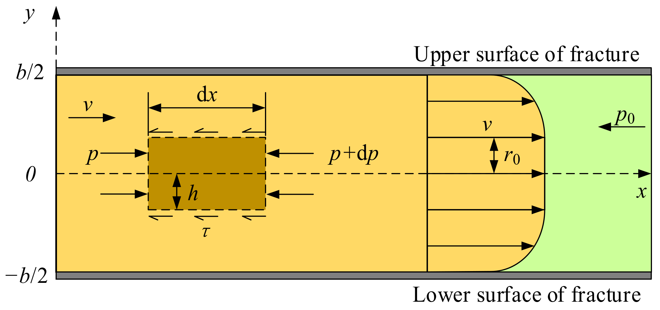
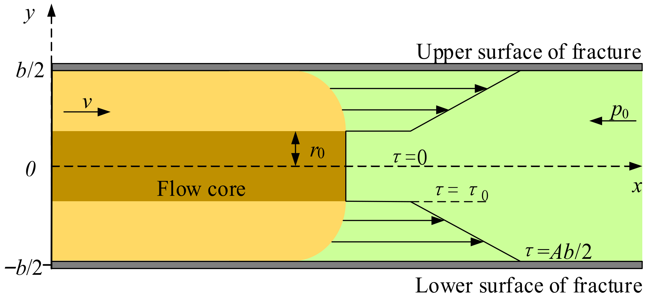
2.2. Basic Equations of the Slurry Flow Model

To study the diffusion law of slurry under fluid–solid coupling, it is necessary to accurately describe all the details of slurry flow in fractures. Therefore, the Navier–Stokes (N-S) equation is used as the motion equation of slurry diffusion, which is based on momentum conservation, and its expression is [45]
ρ v t + ρ v v = p I + μ v + v T 2 3 μ v I + F
where ρ is slurry density, ν is flow velocity, t is grouting time, is divergence operator, p is grout pressure, I is identity tensor, μ is slurry viscosity, and F is volume force.
The flow law of slurry can be expressed by a continuity equation because the flow process is continuous. The slurry is assumed incompressible in the flow process and the continuity equation is based on mass conservation. The continuity equation is expressed as [45]
ρ t + ρ v = 0
In the actual grouting process, the compressibility of the slurry is negligible [1], therefore, Equations (1) and (2) can be rewritten as
ρ v t + ρ v v = p I + μ v + v T + F
ρ v = 0
The inertia term in the equation can be ignored if the viscous deformation stress of slurry is ignored, Equation (3) can be further simplified as [45]
ρ v t = p I + μ v + v T + F
The constitutive relation of slurry flow is expressed the viscosity of slurry, the general expressions is
τ = μ γ ˙ 2 3 μ v I
Ignoring the compressibility of the slurry, Equation (6) can be simplified as
τ = μ γ ˙
In Equation (7), γ ˙ is the engineering strain rate tensor, and the expression is
γ ˙ = v + v T
The viscosity of slurry has time-varying characteristics. The results show that slurry with low water cement ratio (w/c) is a power-law fluid (w/c = 0.5~0.7), the w/c of Bingham fluid slurry is 0.8–1.0, and slurry with w/c > 2.0 is Newtonian fluid [32]. The w/c used for grouting the limestone aquifer in coal measures is generally 1.0, so it is considered as Bingham fluid. The viscosity variation law is in the form of exponential function
μ t = μ t 0 e k t
Therefore, the expression of Bingham fluid constitutive equation is
τ = τ 0 + μ γ ˙
By substituting Equation (9) into Equation (10), the rheological equation of Bingham fluid with the curve which not passing through the origin is usually given as [32]
τ = τ 0 + μ t 0 e k t γ ˙

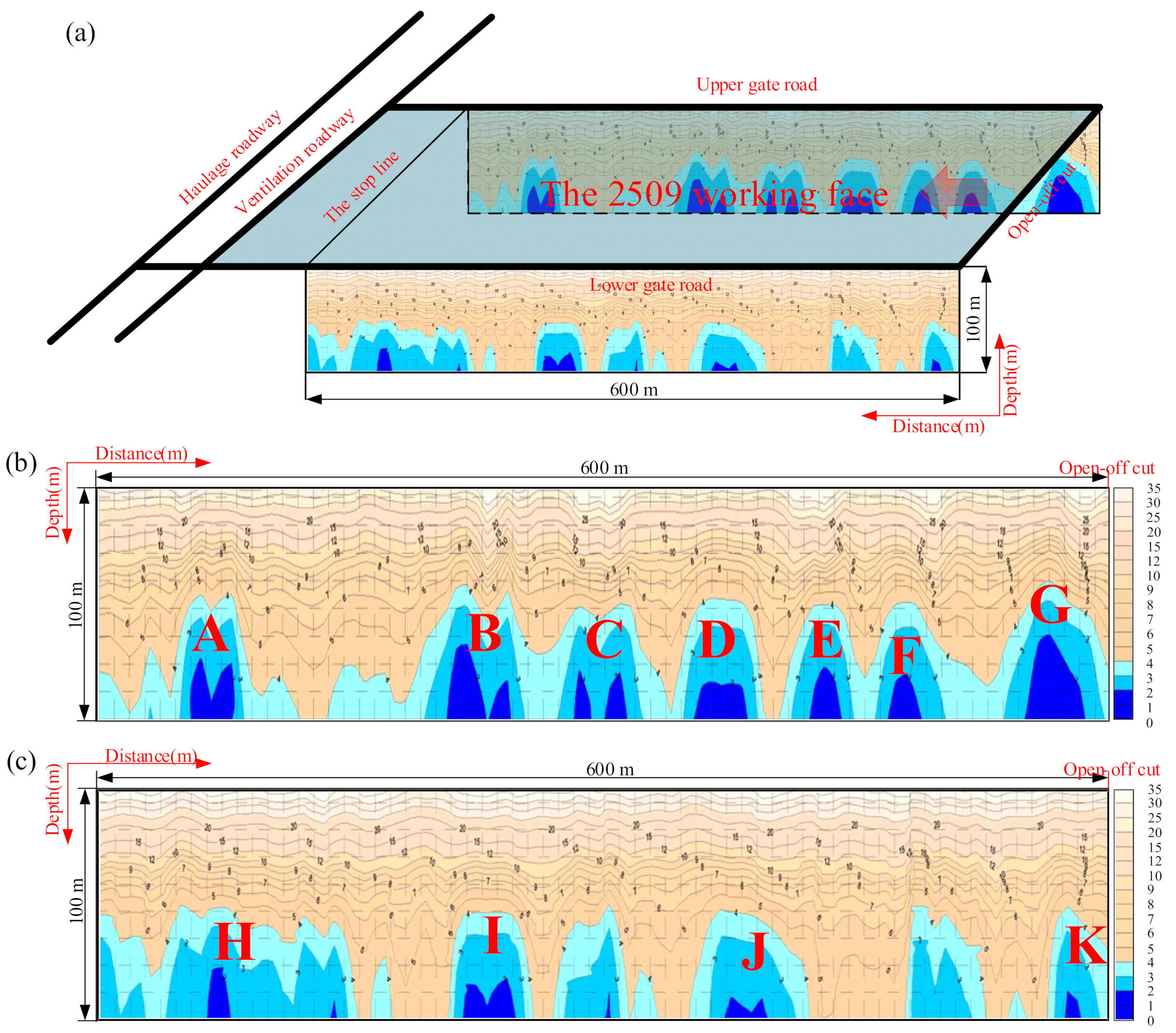
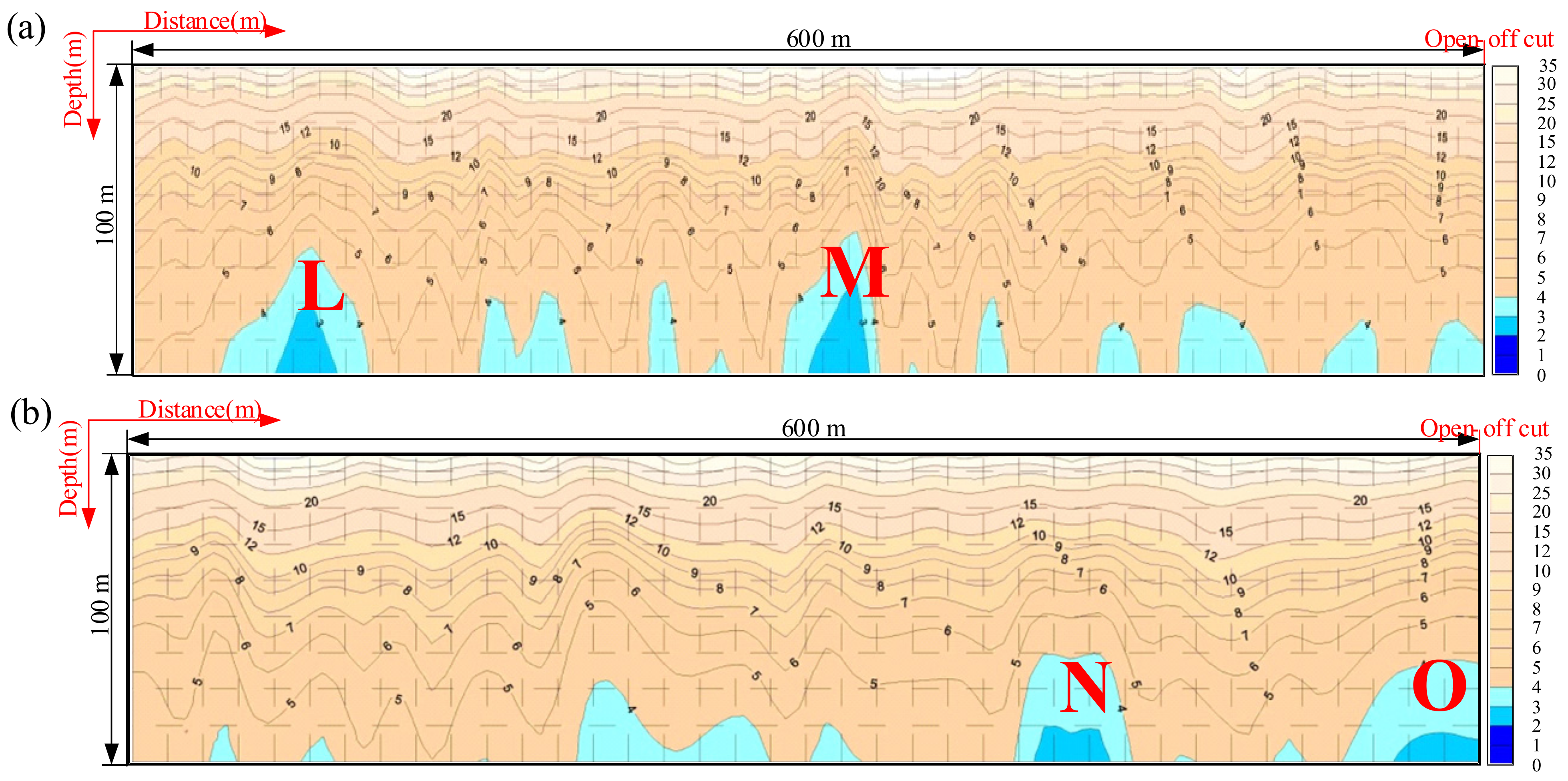
2.3. Detection Methods of Water Abundance of Working Face Floor

Due to the growing threat of water disasters, it has become particularly important to detect water abundance within the seam floor before stoping. On the basis of The Detailed Rules for Water Disaster Prevention and Control of Coal Mines (NCMSA 2018), geophysical and drilling exploration methods should be applied simultaneously when a high-pressure karst aquifer and good water abundance exist in the coal seam floor [46]. Therefore, the transient electromagnetic method (TEM) and drilling exploration were used simultaneously to detect the floor of working face to detect the water bearing properties of the limestone. TEM is based on the time domain electromagnetic induction method. By manually supplying current pulse square wave, the law of the secondary magnetic field is observed to determine the characteristics of the geological structure. In the TEM detection results, the areas where the attenuation rate of the secondary magnetic field slows down mainly indicate areas where the rock stratum is broken, the water-abundance is strong, or a fracture has developed.

3. Mathematical Modeling of the Suspension Diffusion Process

The negligence of the influence of gravity on slurry diffusion in a single plate fracture with equal opening makes it possible to simplify to a two-dimensional problem, and therefore the slurry diffusion form is axisymmetric diffusion. The rectangular coordinate system as shown in the Figure 2 with the symmetry axis and vertical direction of the fracture as the coordinate axis. We analyze the forces in view of the micro element of slurry, taking the fracture center as the symmetry axis.
As shown in Figure 2, b is fracture width, p0 is hydrostatic pressure, dx is micro element length, dp is slurry pressure increment per unit volume, h is half the height of the micro element.
According to the sectional shear force distribution formula at any position in the fracture, the distribution law of shear stress along the fracture width direction can be obtained based on the stress analysis of the micro element
τ = y d p d x
The order of the pressure gradient in x direction is
A = d p d x
Besides, the flow core zone is in the symmetric region of the fracture center when Bingham fluid flows in the fracture (see Figure 3).
Assuming that the shear stress on the edge of the flow core zone is τ0, the distribution of shear stress is [32]
τ = 0 , r 0 < y < r 0 τ 0 , y = ± r 0 A y , r 0 < y < b 2 A b 2 , y = ± b 2
thus, we can obtain
τ 0 = r 0 d p d x
That is, the radius of the flow core area is
r 0 = τ 0 · A 1
In addition, the flow core area is not greater than the fracture width
r 0     b 2
thus, we can obtain [47]
d p d x     2 τ 0 b
Equation (18) shows that there is a starting pressure gradient when unsteady Bingham slurry flows
λ = 2 τ 0 b
Combining Equations (11) and (12) results in
d v d y = τ 0 μ t 0 e k t + y μ t 0 e k t · d p d x
The boundary conditions can be written as
y = ± b 2 , v = 0 y     r 0 , v = v r 0     b 2
Substituting Equation (21) into Equation (20), the benchmark solution of velocity can be given as [47]
v = b 2 4 y 2 8 μ t 0 e k t d p d x τ 0 μ t 0 e k t b 2 y , r 0     y     b 2 b 2 4 r 0 2 8 μ t 0 e k t d p d x τ 0 μ t 0 e k t b 2 r 0 , y     r 0
By integrating and averaging the slurry velocity in the fracture width direction, the average slurry velocity in the fracture can be obtained as [47]
v ¯ = b 2 12 μ t 0 e k t d p d x + 3 τ 0 b + 4 τ 0 3 d p d x 2 b 3
Assuming that the grouting flow is Q, then
Q = 2 π x b v ¯ = b 3 π x 6 μ t 0 e k t d p d x + 3 τ 0 b + 4 τ 0 3 d p d x 2 b 3
Considering the pressure gradient of slurry is generally much greater than its own shear yield stress in grouting engineering, the high-order minor term in Equation (24) can be ignored and integrate x in Equation (24)
p = 3 τ 0 b x 6 μ t 0 e k t Q π b 3 l n x + C
The injection amount of slurry is equal to the diffusion amount of slurry in the fracture according to the law of mass conservation, we have
Q t = b π r t 2 r c 2
The radius of grouting hole, rc, can be ignored since the grouting hole size is very small compared with the slurry diffusion area, Equation (26) can be written as
t = Q π b r t 2
With the diffusion of slurry, the slurry pressure in the fracture gradually decreases. When the farthest point of slurry diffusion is rt, the slurry stops diffusion. Then we can obtain
x = r t , p = p 0 x = r c , t = 0
By substituting Equation (28) into Equation (25), the relationship between grouting pressure and slurry diffusion distance can be obtained
p = p 0 + 3 τ 0 b r t r c + 6 μ t 0 e k Q π b r t 2 Q π b 3 l n r t r c
Equation (29) shows the grouting pressure required for predetermined slurry diffusion radius can be obtained by known grouting hole pressure and injection flow. Slurry properties, fracture parameters, grouting parameters, and water pressure are the parameters affecting the slurry diffusion process.

4. Validation with In Situ Engineering

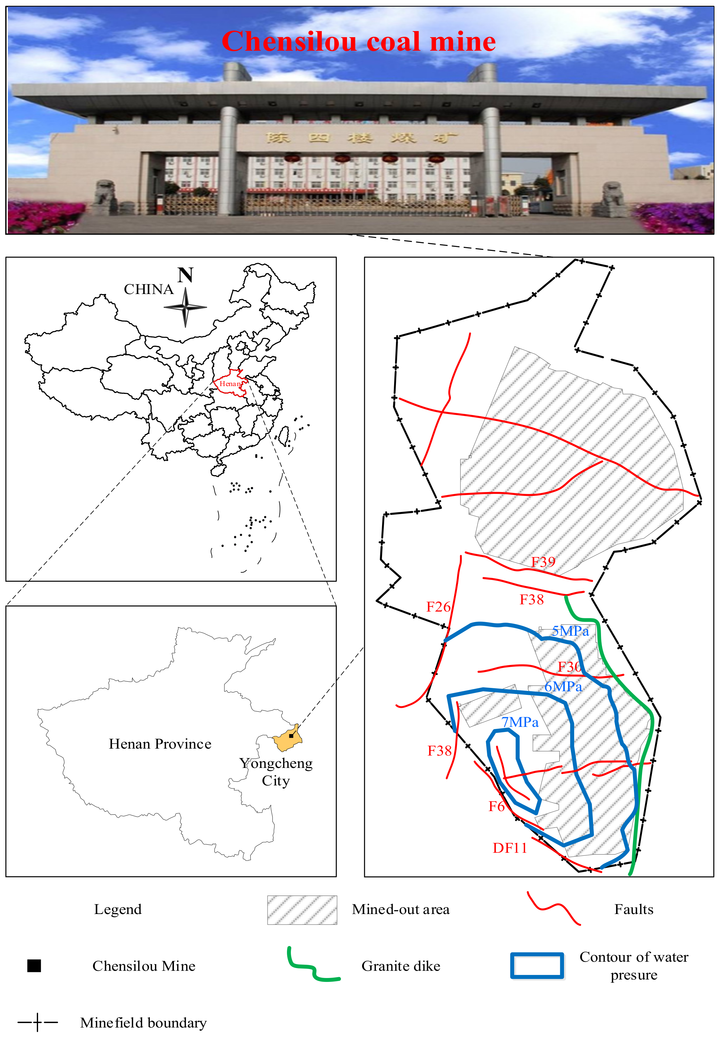
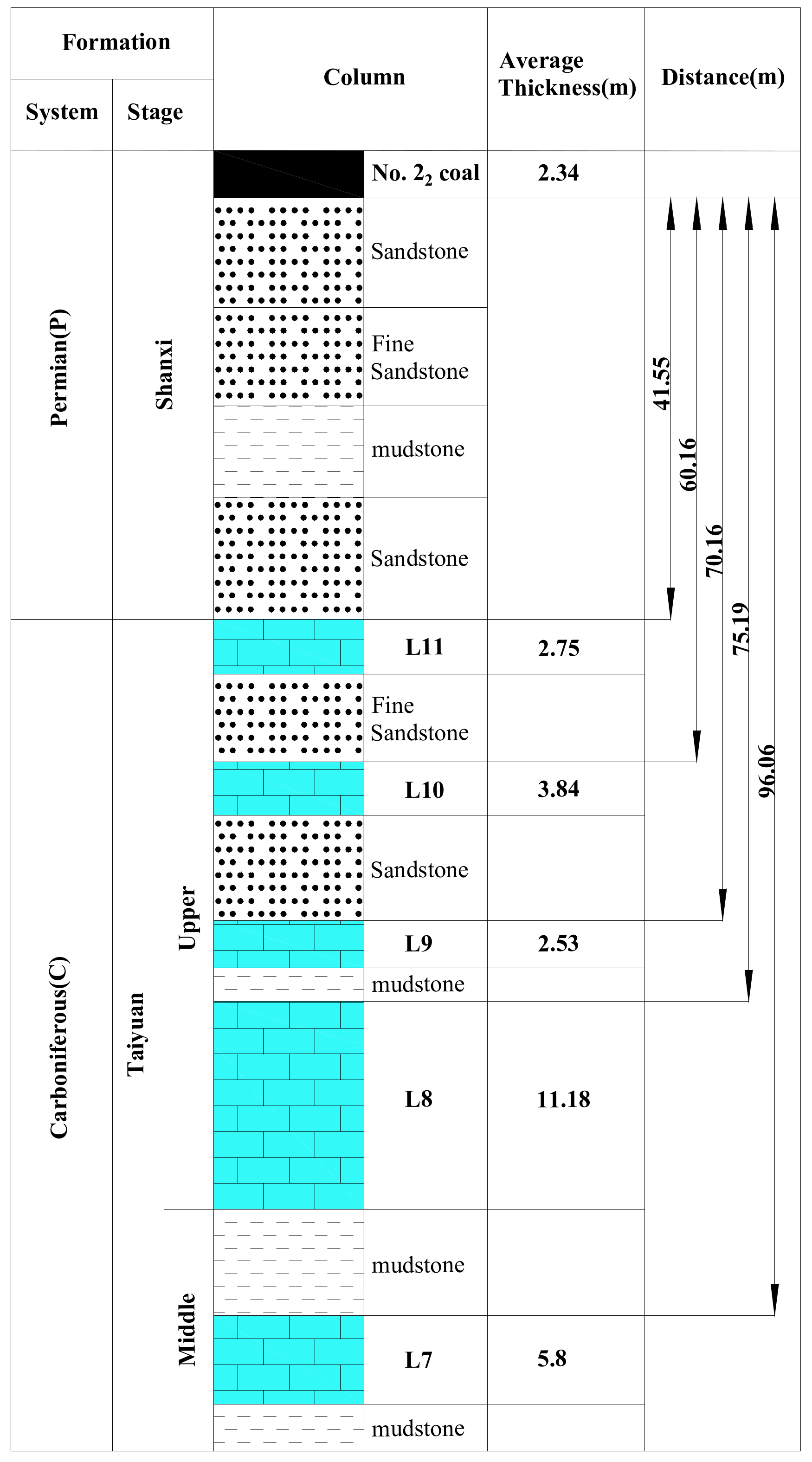
4.1. Overview of the Chensilou Coal Mine

The Chensilou Coal Mine is located in the northeast of Yongcheng-Xiayi coal mining area, Henan Province in China (Figure 4) [48]. It covers an area of 62 square kilometers and has an annual production of 4.5 million metric tons. Working Face 2509 is mined in 22 coal seams, creating a complex structure and fold developed with an average thickness of 2.34 m; 22 normal faults were actually exposed during roadway excavation. According to the hydrogeological data collected during the roadway excavation, karst and fractures are relatively developed, which belong to the aquifer with medium water abundance, and the indirect water-filled source of Working Face 2509 is limestone water in the upper Taiyuan formation (L11–L8). The 22 coal seam floors are 41.55 m, 60.16 m, 70.16 m, and 75.19 m away from L11, L10, L9, and L8 limestone of upper Taiyuan formation, respectively (Figure 5).
According to observation data of water pressure, the floor of Working Face 2509 was subject to the highest hydrostatic pressure of limestone aquifer in the upper Taiyuan formation is 5.34 MPa. The calculation formula of safe head pressure in working face floor according to the NCMSA was [46]
P = T s · M
where P is the water pressure at the base of the floor aquitard (MPa), TS is the water inrush coefficient (MPa/m), the NCMSA states that the water inrush coefficient should not exceed 0.06 MPa/m in an area where the coal seam floor has been fractured or 0.1 MPa/m in an unfractured area, M is the thickness of the aquitard (m).
As the floor of Working Face 2509 was complex a structure and fold developed, so the TS was selected according to the seam floor has been fractured to calculate the thickness of the aquitard. Then [46]
M = P 0.06
Therefore, to make the aquifuge thickness of Working Face 2509’s floor reach the safety aquifuge (89 m) and realize the role of blocking water, it was finally determined to transform L8 to an aquitard, thereby ensuring the safe mining of Working Face 2509.

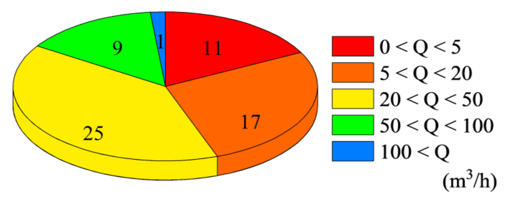
4.2. Detection Results of Water Abundance of Working Face Floor

From Figure 6, we can see that 11 areas showed an attenuated secondary magnetic field under TEM; i.e., zones A, B, …, K, were all located 50 m below the floor of Working Face 2509, and the water-rich areas were located 70 m below working face floor. It was believed that L8 was rich in water in these zones.
As the most direct and accurate method, drilling was often used to determine the distribution of water rich areas in the floor of working face. A total of 63 boreholes were drilled in the L8 aquifer and the water inflow was analyzed to verify the abnormal areas obtained by TEM. For the various boreholes, by water inflow group as shown in Figure 7, the numbers with water inflow above 5 m3/h and exceeding 50 m3/h were 52 and 10, respectively. The drilling results confirmed the existence of the water rich areas in the floor detected by TEM in Working Face 2509.

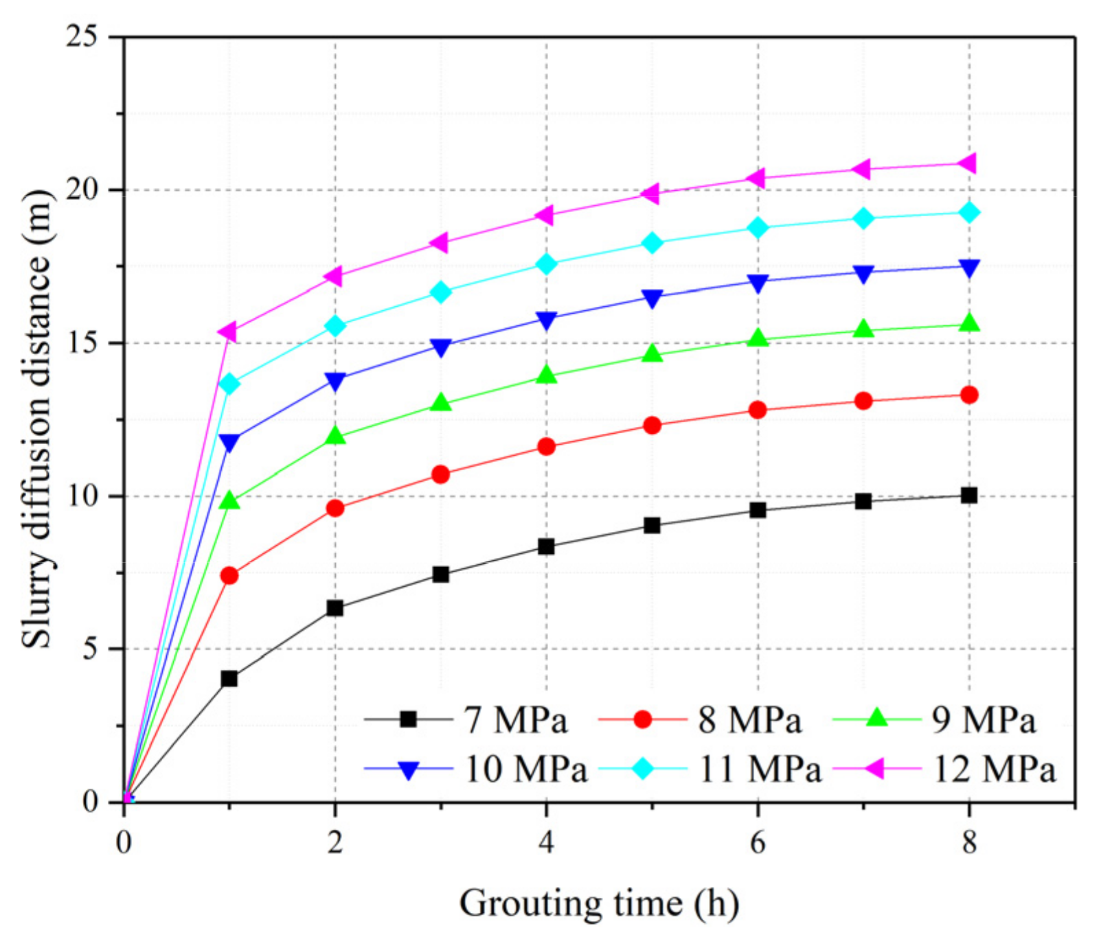
4.3. Determination of Grouting Pressure

Equation (29) shows the relationship between slurry diffusion distance and the grouting pump pressure. According to grouting material of the Chensilou Coal Mine, the following parameters were applied: the hydrostatic pressure p0 was 5.34 MPa, the fracture width b was 0.5 mm, the radius of grouting hole rc was 4.45 × 10⁻² m2, and the slurry injection flow Q was 150 L/min. According to the existing research results, and by taking the effects of the viscosity, separated water ratio, and compressive strength of stone body of slurry into account, the value of w/c of the slurry should be 0.8–1.0. The larger the w/c, the easier the slurry settles and the higher the stone rate [49]. To ensure the filling and blocking effect owing to the large water inflow of the floor of Working Face 2509, the w/c of slurry selected was 1.0, and hence the slurry can be regarded as Bingham fluid.
Substituting the above data into Equation (29), the relationship between the slurry diffusion distance with grouting time under different grouting pressure is shown in Figure 8. As can be seen from Figure 8, the grout diffusion distance has a prominent stage characteristic with the change of grouting pump pressure. The slurry diffusion distance increases with the increase in grouting time with different grouting pressure; however, the growth rate decreases gradually and the change rate of slurry diffusion distance becomes smaller and smaller. When the grouting time reaches a certain value, the slurry diffusion distance will tend to a stable value. If the grouting was continued at this time, the slurry diffusion range was limited and the grouting became more and more difficult.
The general view was that the greater the grouting pressure, the greater the slurry diffusion distance. However, higher grouting pressure will expand the fracture and widen the flow channel, and the time required to reach the limit diffusion distance will also increase, even leading to roadway floor and wall heave, and the slurry will diffuse to the section that does not need reinforcement [1]. Therefore, the grouting pressure should be reasonably determined. The research showed that, after high-pressure grouting, the diffusion distance of Bingham slurry in the fracture development direction was designed as 20–30 m [7], and the conservative value of 20 m was adopted in this paper. According to these analysis results, the final pressure was 12 MPa when the designed slurry diffusion radius rt was 20 m.

4.4. Testing the Effectiveness of Grouting Reinforcement

Grouting effectiveness test was carried out on floor limestone aquifers of Working Face 2509. The results showed that the areas and size of the water rich areas detected by TEM was significantly reduced, indicating that the grouting was effective (see Figure 9).
To determine the effectiveness of the grouting reinforcement, the water rich areas detected by TEM named L, M, N, and O were drilled, two or three test holes in each drilling site. As was already mentioned, it was considered as a safe condition if the water flow of a single test hole was less than 5 m3/h. A total of nine testing holes were drilled and the test results are shown in Table 1, which displays that the smallest water inflow was 0.5 m3/h (N1 hole), and the largest was 4.5 m3/h (L2 hole). Water inflows at all test holes were under 5 m3/h and reduced clearly compared with those listed in Figure 7. It was proved by practice that the grouting reinforcement was successful for no floor water inrush occurred during production of Working Face 2509.

5. Conclusions

To prevent water-bursting disasters from occurring in the floor of a mine in the North China coalfield and to minimize deaths and economic loss, grouting transformation for limestone aquifers in coal floor is an effective means.
In this paper, by regarding slurry as a Bingham liquid of time-dependent behavior, the slurry diffusion mechanism in the horizontal fracture of a fractured aquifer was studied. A theoretical model of one-dimensional permeation grouting considering the temporal and spatial variation of slurry viscosity under constant grouting rate was developed. In this model, the grouting pressure required for predetermined slurry diffusion radius can be obtained by known grouting hole pressure and injection flow.
The mathematical modeling of the suspension diffusion process was verified in the Chensilou Coal Mine. To ensure the safe mining of Working Face 2509, the floor of the working face should be grouted to the bottom of the L8 limestone aquifer, according to the geological conditions of Working Face 2509 and the water inrush coefficient, so as to make the floor a safe water resisting layer of the working face that reaches 89 m. The grouting areas of fractured aquifer were determined according to TEM and drilling results, the grouting pressure with predetermined slurry diffusion distance was determined by using the slurry diffusion theoretical model, and it was found that the final pressure was 12 MPa when the designed slurry diffusion radius was 20 m. To guarantee the grouting quality under high water pressure, cement was regard as the main dry material of the grouting slurry and the grouting method of repeated pipe fixation was used. Finally, it has been proved by practice that the grouting reinforcement was successful in eliminating floor water inrush during production of Working Face 2509.

Author Contributions

M.Z. is responsible for the in situ investigation, data curation, and paper writing; D.M. is responsible for model investigation and funding acquisition; H.B. is responsible for the data processing and part of the paper writing. All authors have read and agreed to the published version of the manuscript.

Funding

The work presented in this paper was financially supported by the National Natural Science Foundation of China (grant no. 41977238 and 52122404) and the Graduate Innovation Program of China University of Mining and Technology.

Institutional Review Board Statement

Not applicable.

Informed Consent Statement

Not applicable.

Data Availability Statement

The study did not report data.

Acknowledgments

We would like to acknowledge the reviewers for their invaluable comments.

Conflicts of Interest

The authors declare no conflict of interest.

References

  1. Hu, Y.; Liu, W.; Shen, Z.; Gao, K.; Liang, D.; Cheng, S. Diffusion mechanism and sensitivity analysis of slurry while grouting in fractured aquifer with horizontal injection hole. Carbonate Evaporite 2020, 35, 1–16. [Google Scholar] [CrossRef]
  2. Zhang, J.; Liu, L.; Zhang, F.; Cao, J. Development and application of new composite grouting material for sealing groundwater inflow and reinforcing wall rock in deep mine. Sci. Rep. 2018, 8, 5642. [Google Scholar]
  3. Ju, J.; Xu, J.; Yang, J. Experimental Study on the Flow Behavior of Grout Used in Horizontal Directional Drilling Borehole Grouting to Seal Mining-Induced Overburden Fractures. Geofluids 2021, 2021, 8823902. [Google Scholar] [CrossRef]
  4. Wang, J.; Ma, D.; Li, Z.; Huang, Y.; Du, F. Experimental investigation of damage evolution and failure criterion on hollow cylindrical rock samples with different bore diameters. Eng. Fract. Mech. 2022, 260, 108182. [Google Scholar] [CrossRef]
  5. Ma, D.; Zhang, J.; Duan, H.; Huang, Y.; Li, M.; Sun, Q.; Zhou, N. Reutilization of gangue wastes in underground backfilling mining: Overburden aquifer protection. Chemosphere 2021, 264, 128400. [Google Scholar] [CrossRef] [PubMed]
  6. Han, C.; Zhang, W.; Zhou, W.; Guo, J.; Yang, F.; Man, X.; Jiang, J.; Zhang, C.; Li, Y.; Wang, Z.; et al. Experimental investigation of the fracture grouting efficiency with consideration of the viscosity variation under dynamic pressure conditions. Carbonate Evaporite 2020, 35, 30. [Google Scholar] [CrossRef]
  7. Liu, S.; Yu, F.; Xu, Y.; Huang, L.; Guo, W. Full-floor Grouting Reinforcement for Working Faces with Large Mining Heights and High Water Pressure: A Case Study in China. Mine Water Environ. 2020, 39, 268–279. [Google Scholar] [CrossRef]
  8. Zhang, C.; Chang, J.; Li, S.; Liu, C.; Qin, L.; Bao, R.; Liu, H.; Cheng, R. Experimental study comparing the microscopic properties of a new borehole sealing material with ordinary cement grout. Environ. Earth Sci. 2019, 78, 149. [Google Scholar]
  9. Ma, D.; Duan, H.; Liu, W.; Ma, X.; Tao, M. Water–Sediment Two-Phase Flow Inrush Hazard in Rock Fractures of Overburden Strata During Coal Mining. Mine Water Environ. 2020, 39, 308–319. [Google Scholar] [CrossRef]
  10. Gong, J.; Rossen, W.R. Modeling flow in naturally fractured reservoirs: Effect of fracture aperture distribution on dominant sub-network for flow. Petrol. Sci. 2017, 14, 138–154. [Google Scholar] [CrossRef] [Green Version]
  11. Shimada, H.; Hamanaka, A.; Sasaoka, T.; Matsui, K. Behaviour of grouting material used for floor reinforcement in underground mines. Int. J. Min. Reclam. Environ. 2014, 28, 133–148. [Google Scholar] [CrossRef]
  12. Chen, Y.; Zhou, C.; Sheng, Y. Formulation of strain-dependent hydraulic conductivity for a fractured rock mass. Int. J. Rock Mech. Min. 2007, 44, 981–996. [Google Scholar] [CrossRef]
  13. Chien, S.; Ou, C. A novel technique of harmonic waves applied electro-osmotic chemical treatment for soil improvement. Appl. Clay Sci. 2011, 52, 235–244. [Google Scholar] [CrossRef]
  14. Ma, D.; Kong, S.; Li, Z.; Zhang, Q.; Wang, Z.; Zhou, Z. Effect of wetting-drying cycle on hydraulic and mechanical properties of cemented paste backfill of the recycled solid wastes. Chemosphere 2021, 282, 131163. [Google Scholar] [CrossRef]
  15. Miller, E.A.; Roycroft, G.A. Compaction Grouting Test Program for Liquefaction Control. J. Geotech. Geoenviron. 2004, 130, 355–361. [Google Scholar] [CrossRef]
  16. Stoll, M.; Huber, F.M.; Trumm, M.; Enzmann, F.; Meinel, D.; Wenka, A.; Schill, E.; Schäfer, T. Experimental and numerical investigations on the effect of fracture geometry and fracture aperture distribution on flow and solute transport in natural fractures. J. Contam. Hydrol. 2019, 221, 82–97. [Google Scholar] [CrossRef]
  17. Draganović, A.; Stille, H. Filtration and penetrability of cement-based grout: Study performed with a short slot. Tunn. Undergr. Space Technol. 2011, 26, 548–559. [Google Scholar] [CrossRef]
  18. Draganović, A.; Stille, H. Filtration of cement-based grouts measured using a long slot. Tunn. Undergr. Space Technol. 2014, 43, 101–112. [Google Scholar] [CrossRef]
  19. Eklund, D.; Stille, H. Penetrability due to filtration tendency of cement-based grouts. Tunn. Undergr. Space Technol. 2008, 23, 389–398. [Google Scholar] [CrossRef] [Green Version]
  20. Funehag, J.; Gustafson, G. Design of grouting with silica sol in hard rock—New methods for calculation of penetration length, Part I. Tunn. Undergr. Space Technol. 2008, 23, 1–8. [Google Scholar] [CrossRef]
  21. Gothäll, R.; Stille, H. Fracture dilation during grouting. Tunn. Undergr. Space Technol. 2009, 24, 126–135. [Google Scholar] [CrossRef]
  22. Ma, D.; Duan, H.; Zhang, J.; Liu, X.; Li, Z. Numerical simulation of water-silt inrush hazard of fault rock: A three-phase flow model. Rock Mech. Rock Eng. 2022; in press. [Google Scholar]
  23. Takano, S.; Hayashi, K.; Zen, K.; Rasouli, R. Controlled Curved Drilling Technique in the Permeation Grouting Method for Improvement Works of an Airport in Operation. Proc. Eng. 2016, 143, 539–547. [Google Scholar] [CrossRef] [Green Version]
  24. Gothäll, R.; Stille, H. Fracture–fracture interaction during grouting. Tunn. Undergr. Space Technol. 2010, 25, 199–204. [Google Scholar] [CrossRef]
  25. Zhang, Q.; Zhang, L.; Liu, R.; Wen, S.; Zheng, Z.; Wang, H.; Zhu, G. Split grouting theory based on slurry-soil coupling effects. Chin. J. Geotech. Eng. 2016, 38, 323–330. [Google Scholar]
  26. Li, P.; Zhang, Q.; Zhang, X.; Li, S.; Zhang, W.; Li, M.; Wang, Q. Analysis of fracture grouting mechanism based on model test. Rock Soil Mech. 2014, 35, 3221–3230. [Google Scholar]
  27. Pinto, A.; Tomásio, R.; Marques, G. Ground Improvement with Jet Grouting Solutions at the New Cruise Terminal in Lisbon, Portugal. Proc. Eng. 2016, 143, 1495–1502. [Google Scholar] [CrossRef] [Green Version]
  28. Amadei, B.; Savage, W.Z. An analytical solution for transient flow of Bingham viscoplastic materials in rock fractures. Int. J. Rock Mech. Min. Sci. 2001, 38, 285–296. [Google Scholar] [CrossRef]
  29. Zhan, K.; Sui, W.; Gao, Y. A model for grouting into single fracture with flowing water. Rock Soil Mech. 2011, 32, 1659–1663. [Google Scholar]
  30. Zhang, G.; Zhan, K.; Sui, W. Experimental investigation of the impact of flow velocity on grout propagation during chemical grouting into a fracture with flowing water. J. China Coal Soc. 2011, 36, 403–406. [Google Scholar]
  31. Ma, D.; Wang, J.; Cai, X.; Ma, X.; Zhang, J.; Zhou, Z.; Tao, M. Effects of height/diameter ratio on failure and damage properties of granite under coupled bending and splitting deformation. Eng. Fract. Mech. 2019, 220, 106640. [Google Scholar] [CrossRef]
  32. Li, S.; Liu, R.; Zhang, Q.; Sun, Z.; Zhang, X.; Zhu, M. Research on C-S Slurry diffusion Mechanism with Time-Dependent Behavior of Viscosity. Chin. J. Rock Mech. Eng. 2013, 32, 2415–2421. [Google Scholar]
  33. Wang, Q.; Feng, Z.; Wang, L.; Tang, D.; Feng, C.; Li, S. Numerical analysis of grouting radius and grout quantity in fractured rock mass. J. China Coal Soc. 2016, 41, 2588–2595. [Google Scholar]
  34. Shen, S.; Wang, Z.; Horpibulsuk, S.; Kim, Y. Jet grouting with a newly developed technology: The Twin-Jet method. Eng. Geol. 2013, 152, 87–95. [Google Scholar] [CrossRef]
  35. Zhang, W.; Zhu, X.; Xu, S.; Wang, Z.; Li, W. Experimental study on properties of a new type of grouting material for the reinforcement of fractured seam floor. J. Mater. Res. Technol. 2019, 8, 5271–5282. [Google Scholar] [CrossRef]
  36. Liu, P.; Liang, S.; Zheng, L. Application of Curtain Grouting Reinforcement Technique in Tunnel with High Water Content Loess Stratum. Chin. J. Undergr. Space Eng. 2018, 14, 1137–1144. [Google Scholar]
  37. Zhang, M.; Zhang, W.; Sun, G. Evalution technique of grouting effect and its application to engineering. Chin. J. Rock Mech. Eng. 2006, 25 (Suppl. S2), 3909–3918. [Google Scholar]
  38. Gustafson, G.; Claesson, J.; Fransson, Å. Steering Parameters for Rock Grouting. J. Appl. Math. 2013, 269594. [Google Scholar] [CrossRef]
  39. Masumoto, K.; Sugita, Y.; Fujita, T.; Martino, J.B.; Kozak, E.T.; Dixon, D.A. A clay grouting technique for granitic rock adjacent to clay bulkhead. Phys. Chem. Earth Parts A B C 2007, 32, 691–700. [Google Scholar] [CrossRef]
  40. Wang, K.; Wang, L.; Ren, B.; Fan, H. Study on Seepage Simulation of High Pressure Grouting in Microfractured Rock Mass. Geofluids 2021, 6696882. [Google Scholar] [CrossRef]
  41. Watanabe, N.; Hirano, N.; Tsuchiya, N. Diversity of channeling flow in heterogeneous aperture distribution inferred from integrated experimental-numerical analysis on flow through shear fracture in granite. J. Geophys. Res. Solid Earth 2009, 114, B04208. [Google Scholar] [CrossRef]
  42. Zhu, D.; Guo, Y.; Wang, W.; Guo, G.; An, T. Grouting Reinforcement Technique in Wind Oxidation Zone by Power Law Superfine Cement Slurry Considering the Time-Varying Rheological Parameters. Adv. Civ. Eng. 2019, 2495850. [Google Scholar] [CrossRef] [Green Version]
  43. Ma, D.; Duan, H.; Zhang, J. Solid grain migration on hydraulic properties of fault rocks in underground mining tunnel: Radial seepage experiments and verification of permeability prediction. Tunn. Undergr. Space Technol, 2022; in press. [Google Scholar]
  44. Ruan, W. Research on diffusion of grouting and basic properties of grouts. Chin. J. Geotech. Eng. 2005, 27, 69–73. [Google Scholar]
  45. Li, S.; Zheng, Z.; Liu, R.; Wang, X.; Zhang, L.; Wang, H. Analysis on fracture grouting mechanism considering grout-rock coupling effect. Chin. J. Rock Mech. Eng. 2017, 36, 812–820. [Google Scholar]
  46. Zhai, M.; Bai, H.; Wu, L.; Wu, G.; Yan, X.; Ma, D. A reinforcement method of floor grouting in high-water pressure working face of coal mines: A case study in Luxi coal mine, North China. Environ. Earth Sci. 2022, 81, 28. [Google Scholar] [CrossRef]
  47. Zhang, L.; Zhang, Q.; Liu, R.; Li, S.; Wang, H.; Li, W.; Zhang, S.; Zhu, G. Penetration grouting mechanism of quick setting slurry considering spatiotemporal variation of viscosity. Rock Soil Mech. 2017, 38, 443–452. [Google Scholar]
  48. Li, H.; Bai, H.; Wu, J.; Wang, C.; Ma, Z.; Du, Y.; Ma, K. Mechanism of water inrush driven by grouting and control measures—A case study of Chensilou mine, China. Arab. J. Geosci. 2017, 10, 468. [Google Scholar] [CrossRef]
  49. Shan, R.; Yang, H.; Zhang, L.; Guo, Z.; Liu, X. Research on proportion and applicable conditions of cement stable slurry. Coal Eng. 2014, 46, 97–100. [Google Scholar]
Figure 1. Disaster caused by floor water inrush in a mine working face.
Mathematics 10 01345 g001
Figure 2. Force analysis of slurry motion [32].
Mathematics 10 01345 g002
Figure 3. Sectional shear force distribution [32].
Mathematics 10 01345 g003
Figure 4. Location of the study area.
Mathematics 10 01345 g004
Figure 5. Histogram of the floor strata.
Mathematics 10 01345 g005
Figure 6. TEM results along the gate road of Working Face 2509 before grouting: (a) TEM detection profile; (b) the upper gate road; (c) the lower gate road.
Mathematics 10 01345 g006
Figure 7. Number of boreholes with different water inflows (Q).
Mathematics 10 01345 g007
Figure 8. Variation of slurry diffusion distance with grouting time under different grouting pressures.
Mathematics 10 01345 g008
Figure 9. TEM results along the gate road of Working Face 2509 after grouting: (a) the upper gate road; (b) the lower gate road.
Mathematics 10 01345 g009
Table 1. Water inflow statistics of the drilling test.
Zone No.Hole No.Water Inflow (m3/h)
LL13
L24.5
MM12
M24
M32
NN10.5
N23
OO13.5
O24
Publisher’s Note: MDPI stays neutral with regard to jurisdictional claims in published maps and institutional affiliations.

