Article

Synthesized Landing Strategy for Quadcopter to Land Precisely on a Vertically Moving Apron

1
Faculty of Mechanical and Aerospace Engineering, Sejong University, Seoul 05006, Korea
2
Department Mechanical Engineering, Vietnam Maritime University, Haiphong 180000, Vietnam
3
Department of Computer Science and Engineering, Sejong University, Seoul 05006, Korea
4
Department of Aerospace Engineering, Convergence Engineering for Intelligent Drone, Sejong University, Seoul 05006, Korea
*
Authors to whom correspondence should be addressed.
Mathematics 2022, 10(8), 1328; https://doi.org/10.3390/math10081328
Submission received: 21 March 2022 / Revised: 8 April 2022 / Accepted: 14 April 2022 / Published: 17 April 2022
(This article belongs to the Special Issue Advanced Control Theory with Applications)

Abstract

:
Quadcopter unmanned aerial vehicles have become increasingly popular for various real-world applications, and a significant body of literature exists regarding the improvement of their flight capabilities to render them fully autonomous. The precise landing onto moving platforms, such as ship decks, is one of the remaining challenges that is largely unresolved. The reason why this operation poses a considerable challenge is because landing performance is considerably degraded by the ground effect or external disturbances. In this paper, we propose a synthesized landing algorithm that allows a quadcopter to land precisely on a vertically moving pad. Firstly, we introduce a disturbance observer-based altitude controller that allows the vehicle to perform robust altitude flight in the presence of external disturbances and the ground effect, strictly proving the system’s stability using Lyapunov’s theory. Secondly, we derive an apron state estimator to provide information on the landing target’s relative position. Additionally, we propose a landing planner to ensure that the landing task is completed in a safe and reliable manner. Finally, the proposed algorithms are implemented in an actual quadcopter, and we demonstrate the effectiveness and applicability of our method through real flight experiments.

1. Introduction

Today, unmanned aerial vehicles (UAVs) have become an important tool in many real-world applications that span from civil to military and scientific areas. Typical applications include ground target surveillance, environmental exploration, delivery services, and search and rescue [1]. Quadcopters are one of the most popular and important types of UAV. They possess several favorable qualities that render them superior to other types of UAV, namely, a simple structure, affordable cost, high maneuverability, and reliable operation [2]. These attributes and the multitude of applications have made them a highly popular topic for research.
However, the quadcopter is also a nonlinear, underactuated system [3], which makes it difficult to maintain tight performance control. The inevitable presence of system uncertainties and disturbances makes it very difficult to achieve highly stable and robust flights. A variety of control algorithms have been introduced to address these issues, including the proportional–integral–derivative (PID) technique [4], the backstepping algorithm [5], the sliding mode control (SMC) [6,7], the disturbance observer-based approach [8], the adaptive fast finite-time control [9], and the resilient method [10]. Each solution has its specific advantages and shortcomings, and the choice of algorithm usually depends on the type of application. Nevertheless, the diverse and ubiquitous applicability of quadcopters means that the search for new algorithms to improve their autonomous control performance remains an ongoing and rewarding challenge for the scientific community.
Since quadcopters can only carry fairly small payloads, the size and capacity of their battery are also limited, which requires them to frequently land to be recharged. Furthermore, in many applications, such as autonomous delivery, search and rescue, and environmental exploration, landing is a core mission component that the quadcopter needs to achieve without fail. Hence, finding an efficient and reliable autonomous landing algorithm is both important and necessary. To that end, many approaches have been investigated, including a vector field-based precision landing strategy [11] and an adaptive landing controller using optical flow for use in a micro-air vehicle [12]. However, in both studies, the landing platform was flat and stationary. In contrast, a control method for a quadcopter to land robustly on a tilting pad has been presented in [13], while in [14], the vehicle successfully lands on a slope through a vision-based surface orientation estimator.
Thus, while the problem of landing on stationary platforms has been addressed in many studies, resulting in a variety of solutions, when it comes to landing on a moving apron, those solutions cannot deliver satisfactory performance, which is why many researchers have directed their efforts toward solving this issue. One of the proposed solutions involves a motion-capture-system-based control method that allows a quadcopter to land on a vertically moving apron [15]. However, this solution is both expensive and limited to indoor applications due to its reliance on an indoor-based vision system. Meanwhile, by using global positioning system data, one study succeeded in having quadcopters perform a search and land on a mobile landing pad using a vision-based controller [16]. Optical cameras were also integrated with a variety of other control strategies, including PID, backstepping, fuzzy logic, and neural networks [17,18]. However, due to their operation on the visual part of the spectrum, the cameras used in these studies may not be appropriate in low light conditions, i.e., if the vehicle is operated at night or in areas that lack sufficient light. At the same time, other studies have focused on improving the hardware and both the accuracy and reliability of algorithms that estimate the state of the landing pad [19,20]. Tracking gimbals and highly visually detectable landing surfaces were used to enhance the target’s detectability and reduce the target-lost probability [21,22].
Ship decks are notoriously difficult landing platforms for quadcopters, purely because of the large external disturbances caused by the sea state and weather. Nevertheless, the heaving vessel deck landing problem has been addressed by some studies using a variety of control algorithms, including PID [23], SMC [24], and robust controllers [25,26]. However, none of these studies went beyond numerical simulations. To the best of our knowledge, only one study in the literature has managed to solve the problem of landing on a vertically moving apron (employing cameras operating in the visual part of the spectrum) and demonstrated the solution using actual vehicles and ship deck emulators [27]. However, the emulators used in that study were only capable of small vertical movements compared to the heaving motion of actual ship decks. Thus, a solution that has been fully tested in a realistic setting involving a vertically moving pad, such as a ship deck, remains to be found and is urgently needed for many applications, including ocean observations, disaster monitoring, and search and rescue. Here, in an effort to achieve a more complete and applicable landing algorithm, we propose a novel autonomous landing strategy that enables quadcopters to perform precision landings on a heaving apron under the influences of external disturbances. Our work contributes to and extends the current knowledge in four ways:
(1) A disturbance observer-based (DOB) controller is proposed to enable robust landing performance in disturbed environments. Lyapunov theory is used to perform a strict stability analysis of this closed-loop system.
(2) An apron state estimator (ASE) is introduced to provide the quadcopter’s landing planner and controller with stable and reliable data, significantly improving landing accuracy. Additionally, a landing planner is proposed to govern the landing task in a safe and precise manner.
(3) An infrared (IR) camera is used to determine the apron state, providing this approach with two crucial advantages compared with cameras operating in the visual range: (i) It remains functional even in dark or low-light environments, and (ii) it reduces the cost of the landing system and simplifies its setup as it can function using commercially available IR LEDs.
(4) Unlike existing studies that either restricted themselves to the presentation of results from numerical simulations [23,24,25,26] or where the experimental setup lacked the necessary realism to approximate real-world conditions [27], we devised an experimental setup with a moving apron to realistically simulate the heaving motion of a ship deck. The effectiveness of our strategy is tested experimentally, and the quadcopter needs to precisely land on the vertically moving apron. The successful completion of these realistic experiments demonstrates that our method is suitable for use in real-world applications.
The main advantages of this approach are best highlighted through a direct comparison with the most related work in the literature [27] (Table 1).
The remainder of this paper is structured as follows: Section 2 introduces the quadcopter dynamical model and problem statement. In Section 3, we present the main results, including the disturbance observer-based altitude control, the apron state estimator, and the landing planner. Section 4 describes the experimental setup and results while the conclusions are provided in Section 5.

2. Quadcopter Dynamics and Problem Statement

A typical configuration of the quadcopter is shown in Figure 1. With four motors, the vehicle can generate thrust forces F i ( i = 1 , . . . , 4 ) that contribute to the control inputs as:
u z = F 1 + F 2 + F 3 + F 4 u ϕ = L ( F 2 F 4 ) u θ = L ( F 3 F 1 ) u ψ = c d ( F 1 + F 2 F 3 + F 4 )
The quadcopter dynamics was described and verified in various existing studies [27,28,29]. Its full cascaded dynamical model can be described as:
ϕ ¨ = J y J z J x θ ˙ ψ ˙ + 1 J x u ϕ θ ¨ = J z J x J y ϕ ˙ ψ ˙ + 1 J y u θ ψ ¨ = J x J y J z ϕ ˙ θ ˙ + 1 J z u ψ x ¨ = 1 m ( c ϕ s θ c ψ + s ϕ s ψ ) u z y ¨ = 1 m ( c ϕ s θ s ψ s ϕ c ψ ) u z z ¨ = g + 1 m ( c ϕ c θ ) u z
with x , y being the vehicle’s position, z the altitude, and ϕ , θ , ψ the attitude (in the inertial coordinate { E } ); m is the mass; J x , J y , and J z are the inertia momentum about the x , y , and z axes; g is the gravitational acceleration; L is the vehicle’s arm length; and c d is the force-to-torque coefficient. The symbols c · and s · represent c o s ( · ) and s i n ( · ) , respectively.
Taking external disturbances into account, the altitude dynamics is rewritten as [28]:
z ¨ = g + γ m ( c ϕ c θ ) u z + δ
where
γ = 1 1 ρ r 2 / ( 4 z p ) 2
with ρ R + , r is the propeller radius, and z p is the distance from the propeller’s center to the ground; δ is the external disturbance.
Assumption 1.
The disturbance, δ, and its time derivative are bounded, i.e., the followings holds: δ δ L and δ ˙ v δ L , where δ L and v δ L are unknown constants.
Since the determination of an exact value of ρ is difficult, its nominal value, ρ ¯ , is used. Let γ ¯ be the nominal value of γ correspondingly, and let Δ γ = γ γ ¯ . Thus, (3) becomes:
z ¨ = g + γ ¯ + Δ γ m ( c ϕ c θ ) u z + δ
Let d = δ + c ϕ c θ m Δ γ u z be the lumped disturbance. Then, (3) is rewritten as:
z ¨ = g + γ ¯ m ( c ϕ c θ ) u z + d
In the following sections, we design a disturbance observer-based controller u z to manipulate the vehicle to land on a vertically moving apron, i.e., the desired altitude of the quadcopter is time-varying under the ground effect and external disturbances.

3. Main Results

3.1. Disturbance Observer-Based Altitude Controller

Let the altitude tracking error be defined as:
e z = z z d
Then, we have the following:
e ˙ z = z ˙ z ˙ d
and
e ¨ z = z ¨ z ¨ d
From (6) and (9), we have the dynamics of the altitude tracking error as:
e ¨ z = g + γ ¯ m ( c ϕ c θ ) u z + d z ¨ d
Lemma 1
([30]). Given a system x ˙ = h ( x ) + u + ξ ( t , x ) , where x R n , h ( x ) is a vector of smooth functions, and u is the control signal, then the following disturbance observer is introduced:
ξ ^ ( t , x ) = μ + λ ( x ) μ ˙ = L ( x ) μ L ( x ) ( h ( x ) + u + λ ( x ) )
where L ( x ) = λ ( x ) / x denotes the observer gain, and λ ( x ) is selected in such way that L ( x ) is a positive-definite gain matrix for all x R n . The disturbance observer (11) ensures that the observation error ξ ˜ ( t , x ) = ξ ( t , x ) ξ ^ ( t , x ) exponentially tends to a residual set containing the zero whose radius is adjustable by tuning the function λ ( x ) . If δ L = 0 , the observer error exponentially tends to the origin.
Let (10) be rewritten as:
e ¨ z = ν z
with ν z being a virtual control input:
ν z = g + γ ¯ m ( c ϕ c θ ) u z + d z ¨ d
The selection of equivalent input ν z is based on the stability of the altitude error dynamics. Thus, by defining the following variable:
σ = e ˙ z + Λ e z ( e z 2 + 1 ) 1 2
a control law is proposed as:
ν z = K e ˙ z K Λ e z ( e z 2 + 1 ) 1 2
where K and Λ are control gains. By substituting (16) into (13), the following disturbance observer-based controller is obtained:
u z = m γ ¯ c ϕ c θ [ K e ˙ z K Λ e z ( e z 2 + 1 ) 1 2 ζ + g + z ¨ d d ^ ]
where:
ζ = Λ e z ˙ ( e z 2 + 1 ) 3 2
d ^ = μ + Γ σ
μ ˙ = Γ μ Γ [ g z ¨ d + γ ¯ m ( c ϕ c θ ) u z + ζ + Γ σ ]
where d ^ is the estimated disturbance, and Γ is the observer gain. Then, the time-derivative of (14) along (10) gives:
σ ˙ = e ¨ z + Λ e z ˙ ( e z 2 + 1 ) 3 2 = g + γ ¯ m ( c ϕ c θ ) u z + d z ¨ d + Λ e z ˙ ( e z 2 + 1 ) 3 2 = K e ˙ z K Λ e z ( e z 2 + 1 ) 1 2 + d ˜
where d ˜ = d d ^ .
From (18) and (19), one can obtain:
d ˜ ˙ = d ˙ + Γ μ + Γ [ g z ¨ d + γ ¯ m ( c ϕ c θ ) u z + ζ + Γ σ ] Γ σ ˙
which can be simplified as:
d ˜ ˙ = d ˙ Γ d ˜
The stability of the closed-loop system with the proposed disturbance observer-based controller is summarized in the following theorem.
Theorem 1.
For a given time-varying altitude command z d , the control law (16) asymptotically stabilizes the quadcopter system (2) with the vertical dynamics under the lumped disturbance as described in (6), i.e., the altitude tracking error, e z , is forced to zero in a finite time.
Proof. 
Consider the following Lyapunov candidate function:
V = ( e z 2 + 1 ) 1 2 1 + 1 2 σ 2 + 1 2 d ˜ 2
Then, the derivative of V is:
V ˙ = e ˙ z e z ( e z 2 + 1 ) 1 2 + σ ˙ σ + d ˜ ˙ d ˜
Substituting (20) and (22) into (24) yields:
V ˙ = e z ( e z 2 + 1 ) 1 2 σ e z ( e z 2 + 1 ) 1 2 Λ e z ( e z 2 + 1 ) 1 2 K σ 2 + σ d ˜ + d ˙ d ˜ Γ d ˜ 2
Considering the fact that a b ϵ a 2 + b 2 / ( 4 ϵ ) , ∀ ϵ > 0 , one obtains:
V ˙ ( Λ ϵ ) e z 2 ( e z 2 + 1 ) 1 ( K 1 4 ϵ ϵ ) σ 2 ( Γ 1 4 ϵ ϵ ) d ˜ 2 + 1 4 ϵ d ˙ 2 λ Ω 2 + ε
where λ : = m i n ( λ 1 , λ 2 , λ 3 ) , with λ 1 : = Λ ϵ > 0 , λ 2 : = K 1 4 ϵ ϵ > 0 , and λ 3 : = Γ 1 4 ϵ ϵ > 0 ; Ω : = [ e z ( e z 2 + 1 ) 1 2 , σ , d ˜ ] T ; moreover, ε : = sup t 0 ( 1 4 ϵ d ˙ 2 ) .
Following the comparison principle in [31], inequality (26) indicates the closed-loop system is uniformly and ultimately bounded, and the altitude tracking error converges to a small neighborhood of the origin. This completes the proof. □

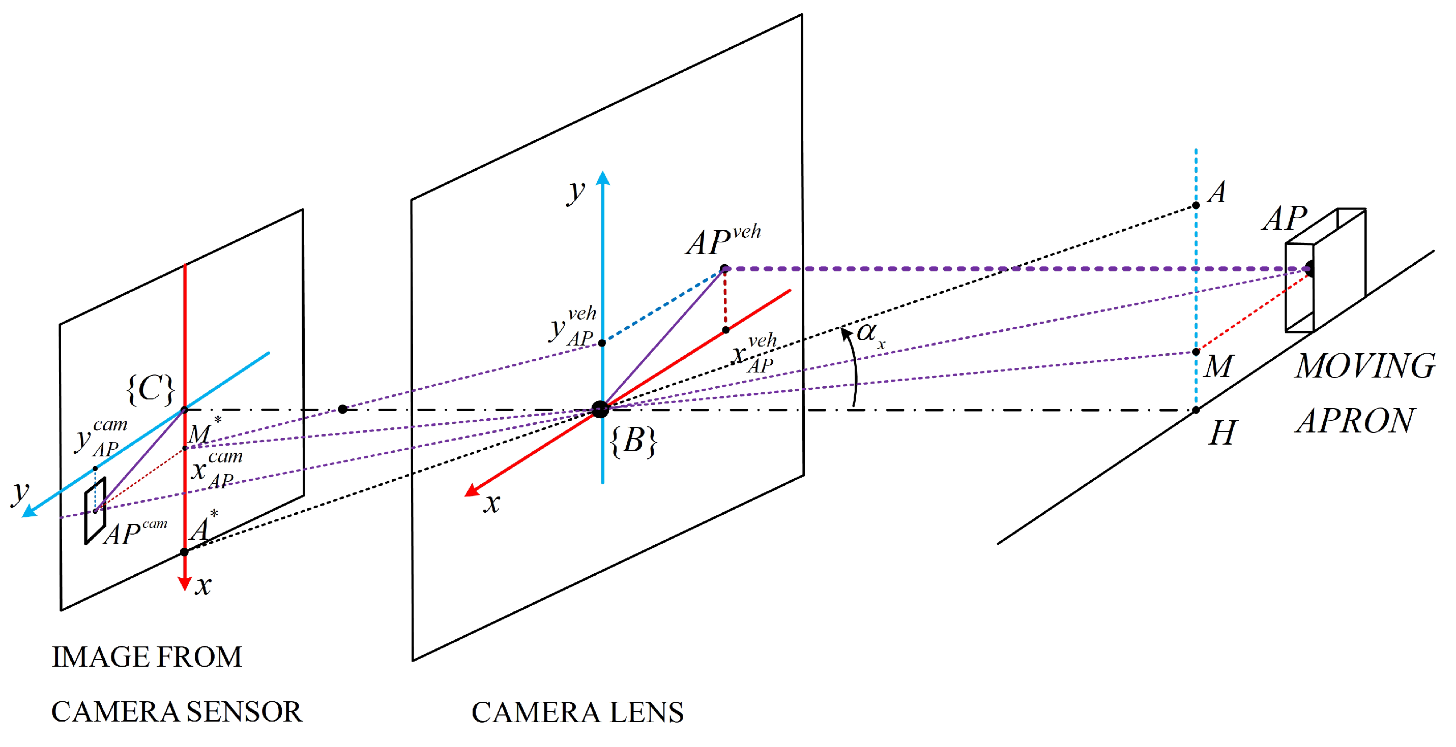
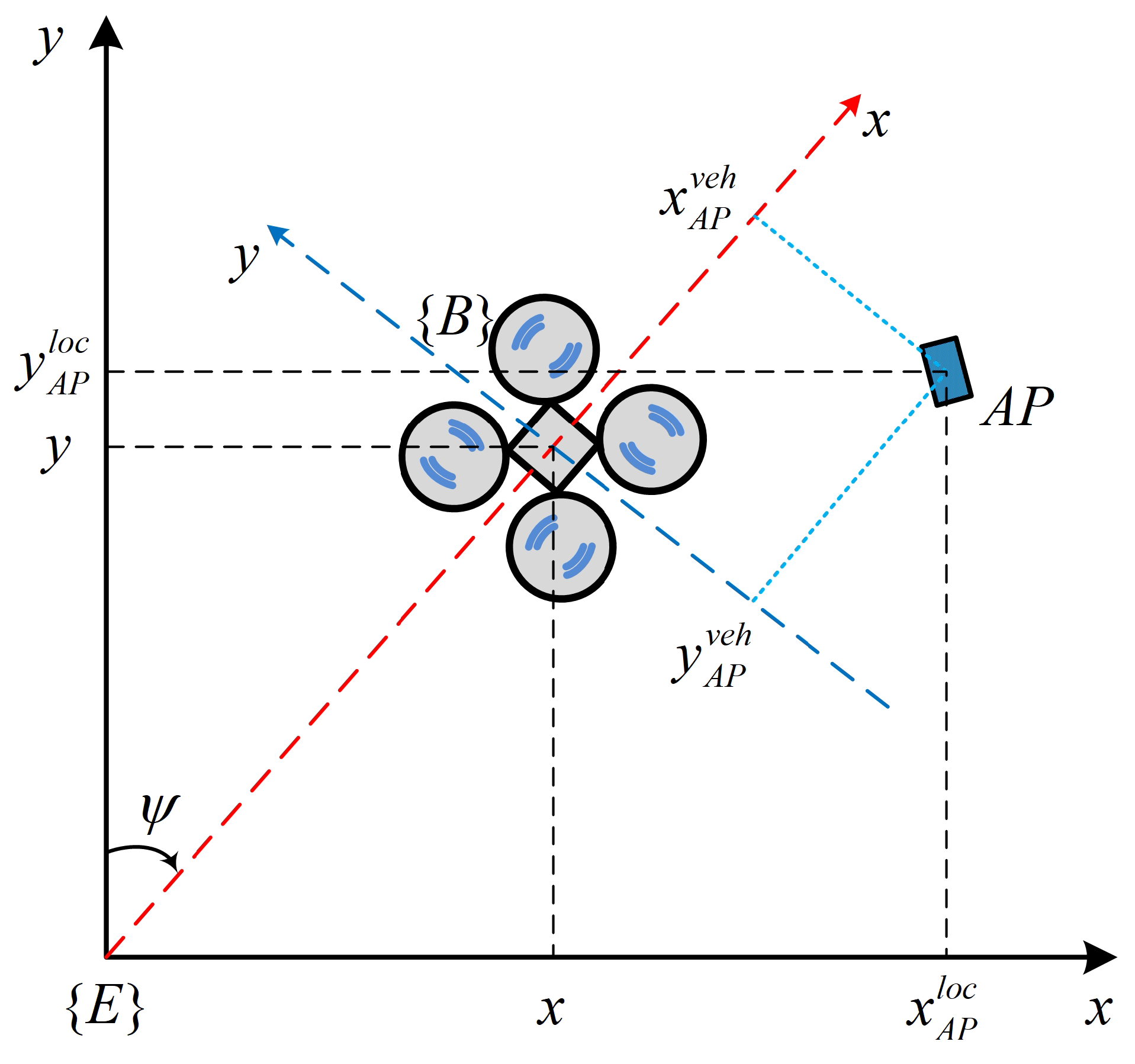
3.2. Apron State Estimator

Based on geometrical optics analyses, we derive an apron state estimator (ASE) which processes the IR camera’s data to provide the landing controller with reliable information about the apron’s position and velocity.
From the geometrical optics scheme in Figure 2, the raw position ( x A P v e h and y A P v e h ) of the apron, in the quadcopter’s body-fixed coordinate { B } , can be determined.
First, considering two pairs of similar triangles ( M H B , A * C B ) and ( A H B , A * C B ), one obtains:
H M ¯ H B = C M * ¯ C B t a n α x = C A * C B
with α x and α y being the fields of view (FOV) of the IR camera in its horizontal and vertical axes, respectively. Manipulating (27) yields:
H M ¯ = H B t a n α x C A * C M * ¯
Substituting y A P v e h = H M ¯ , z = H B , x m a x c a m = C A * , and x A P c a m = C M * ¯ into (28), we have:
y A P v e h = z t a n α x x m a x c a m x A P c a m
Similarly, the following can be obtained:
x A P v e h = z t a n α y y m a x c a m y A P c a m
Next, the raw position, obtained from (29) and (30), will be used in a Kalman filter [32] to estimate the corresponding velocity. In order to apply the filter, a state model and a measurement model need to be determined.
Let p A P | t = [ x A P | t v e h , v x A P | t v e h , y A P | t v e h , v y A P | t v e h ] T be the apron’s state (including position and velocity) at the time point t. Then, the state at the time point t + 1 can be computed as:
p A P | t + 1 = A K F p A P | t + w t
where t s represents the measurement’s sampling time; w t = [ 0 , w x , 0 , w y ] T is a vector of the state transition noises; and A K F is the system state matrix:
A K F = 1 t s 0 0 0 1 0 0 0 0 1 t s 0 0 0 1
The measurement can be modeled as:
z t = H K F p A P | t + υ t
with z t being the measurement vector and υ t = [ υ x , υ y ] T being the measurement noises. The measurement matrix H K F is defined as:
H K F = 1 0 0 0 0 0 1 0
To be used in the quadcopter’s controllers, the landing target state in { B } needs to be converted to one in { E } (see Figure 3) through the following coordinate transformation:
p A P l o c = s ψ 0 c ψ 0 0 s ψ 0 c ψ c ψ 0 s ψ 0 0 c ψ 0 s ψ p A P + p Q l o c
where p A P l o c is the apron’s state and p Q l o c is the quadcopter’s state in { E } .

3.3. Landing Planner

In order for the landing mission to be achieved safely and precisely, an autonomous landing planner is proposed. The planner will enable a predefined procedure as the landing task is triggered. The autonomous landing procedure is as follows:
  • Step 1: Start.
  • Step 2: Horizontally move to the landing area.
  • Step 3: If the apron is visible, jump to Step 4. Otherwise, jump to Step 11.
  • Step 4: Horizontally approach the apron.
  • Step 5: If the quadcopter and the apron are horizontally close, jump to Step 6. Otherwise, jump to Step 4.
  • Step 6: Descend over the apron.
  • Step 7: If the apron is lost, jump to Step 8. Otherwise, jump to Step 5.
  • Step 9: If the quadcopter and the apron are vertically close, jump to Step 10.
  • Step 10: Final approach the apron’s surface.
  • Step 11: If the quadcopter has used the maximum search attempts, jump to Step 14. Otherwise, jump to Step 12.
  • Step 12: Climb to the search altitude.
  • Step 13: If the landing target is visible, jump to Step 4. Otherwise, jump to Step 14.
  • Step 14: Land at its current position.
  • Step 15: If the quadcopter is fully landed, jump to Step 16.
  • Step 16: Landing complete.

4. Experiment and Discussions

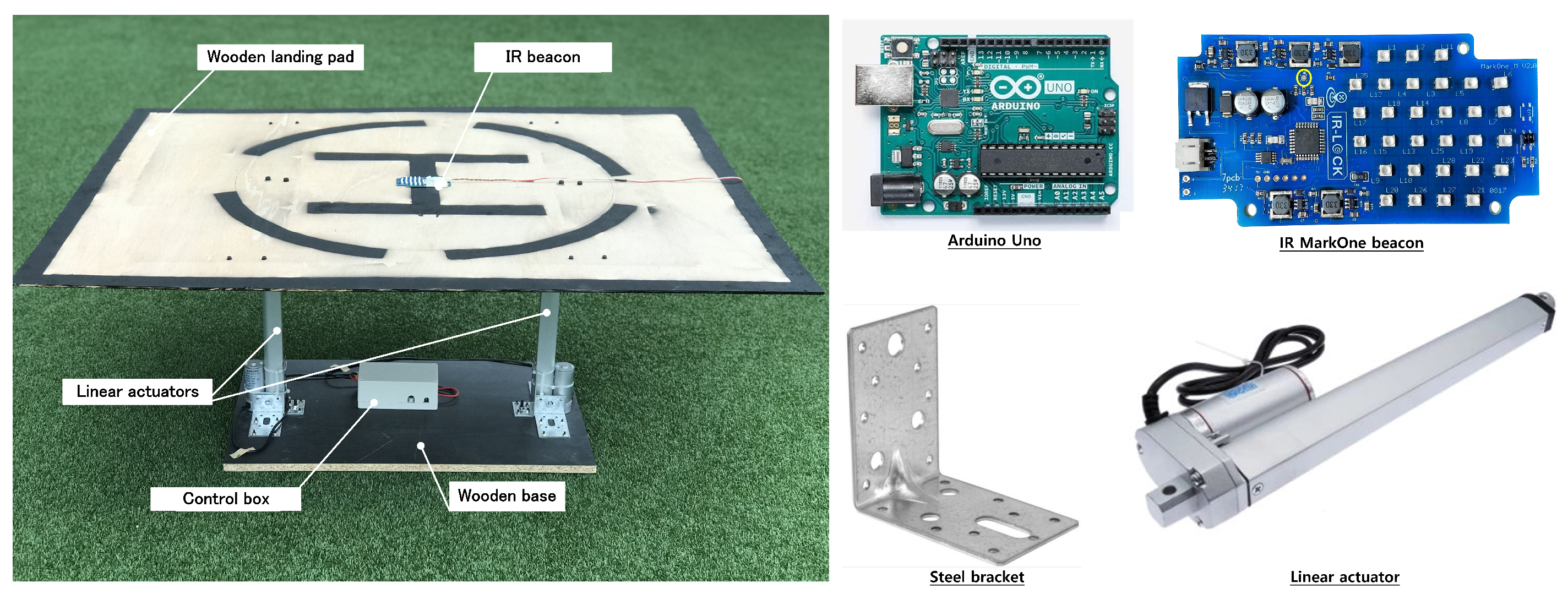
4.1. Experimental Setup

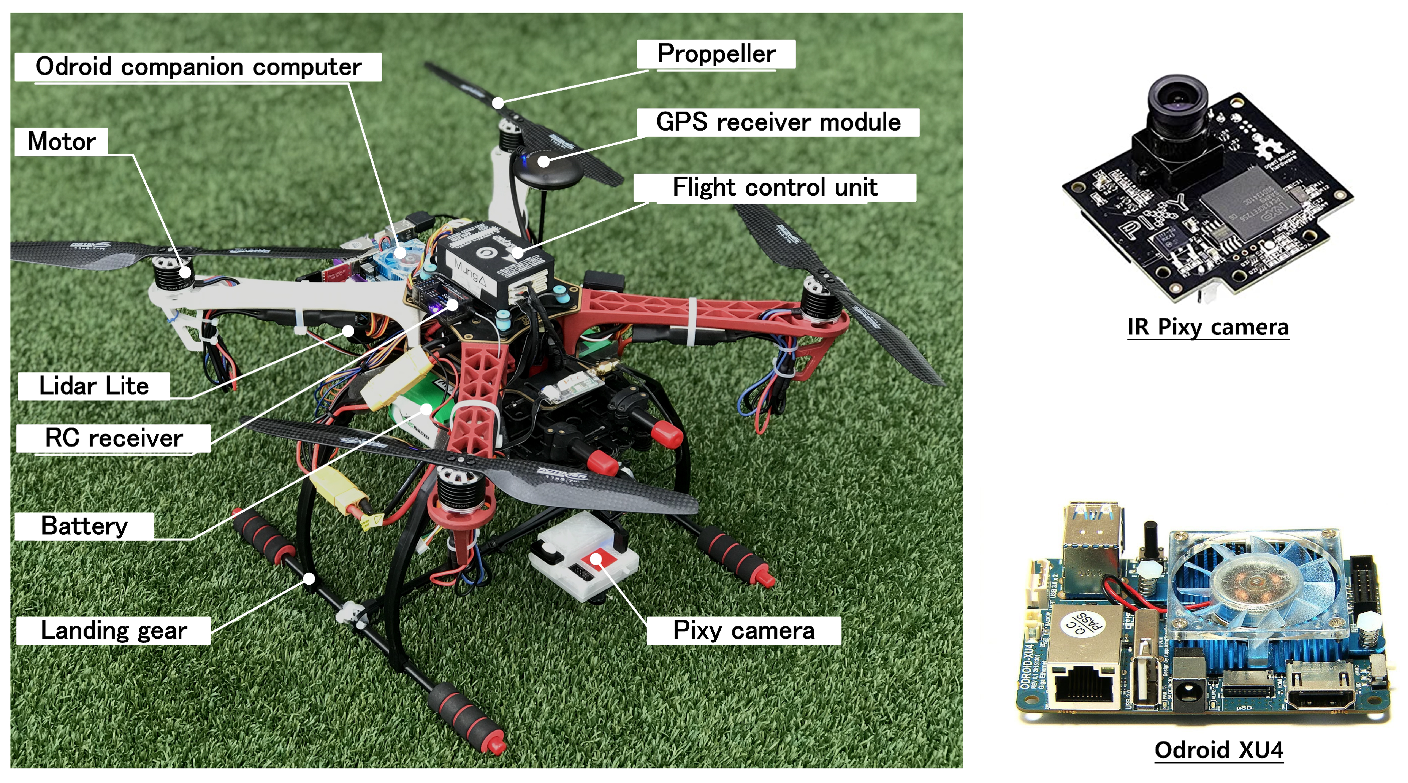
4.1.1. Experimental Quadcopter Platform

The quadcopter used in the experiment (Figure 4) is operated by an onboard computer Pixhawk FCU. The vehicle is also equipped with an inertial navigation system (INS), which is for its attitude and acceleration determination purpose. A light-detecting and ranging sensor LidarLite V3 is used to provide the altitude information, and a commercial GPS receiver is used for positioning. Additionally, a Li-Po battery and a power regulator for power supply, a set of radio frequency transmitters/receivers for manual control, and a pair of wireless telemetry for ground station monitoring are utilized.
We use an IR Pixy camera [33] to detect the apron and determine its position. The measurement is updated at a frequency of 50 Hz. In addition, we use an Odroid XU4 [34] as a companion computer to operate the proposed algorithms (Figure 5). This Odroid XU4 and the Pixhawk FCU exchange data through the Mavlink protocol. Detailed information about the quadcopter dynamic parameters and the IR camera’s FOV is listed in Table 2.

4.1.2. Vertical Moving Apron
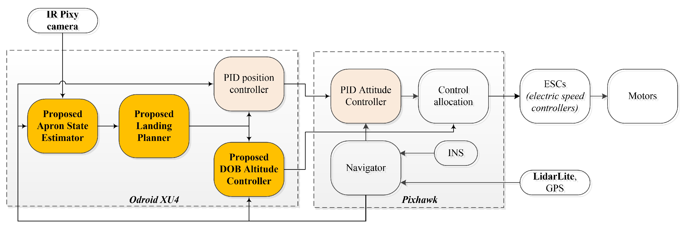
The vertical moving apron is devised to simulate an actual landing pad on a vessel deck (Figure 6). On the apron’s surface, we attach an IR MarkOne beacon which plays the role of a landing target to be detected by the IR camera. The heaving motion is generated by two linear actuators (i.e., cylinders) which are controlled by an Arduino Uno [35] through two motor drivers. Once the platform is powered, it is able to create a maximum lift force of 200 N. The apron can move up and down at a speed of 90 mm/s, and the vertical stroke is of 300 mm (see Table 3).

4.1.3. Software

While the low-level processing (including attitude controllers and a navigator) is operated on the Pixhawk FCU at 400 Hz, the proposed algorithms are implemented on the Odroid XU4 and run at 100 Hz (Figure 5). The DOB altitude controller parameters are listed in Table 4. It is worth noting that the horizontal position and the attitude controllers are designed using the PID control technique and will not be described since they are beyond the scope of this paper.

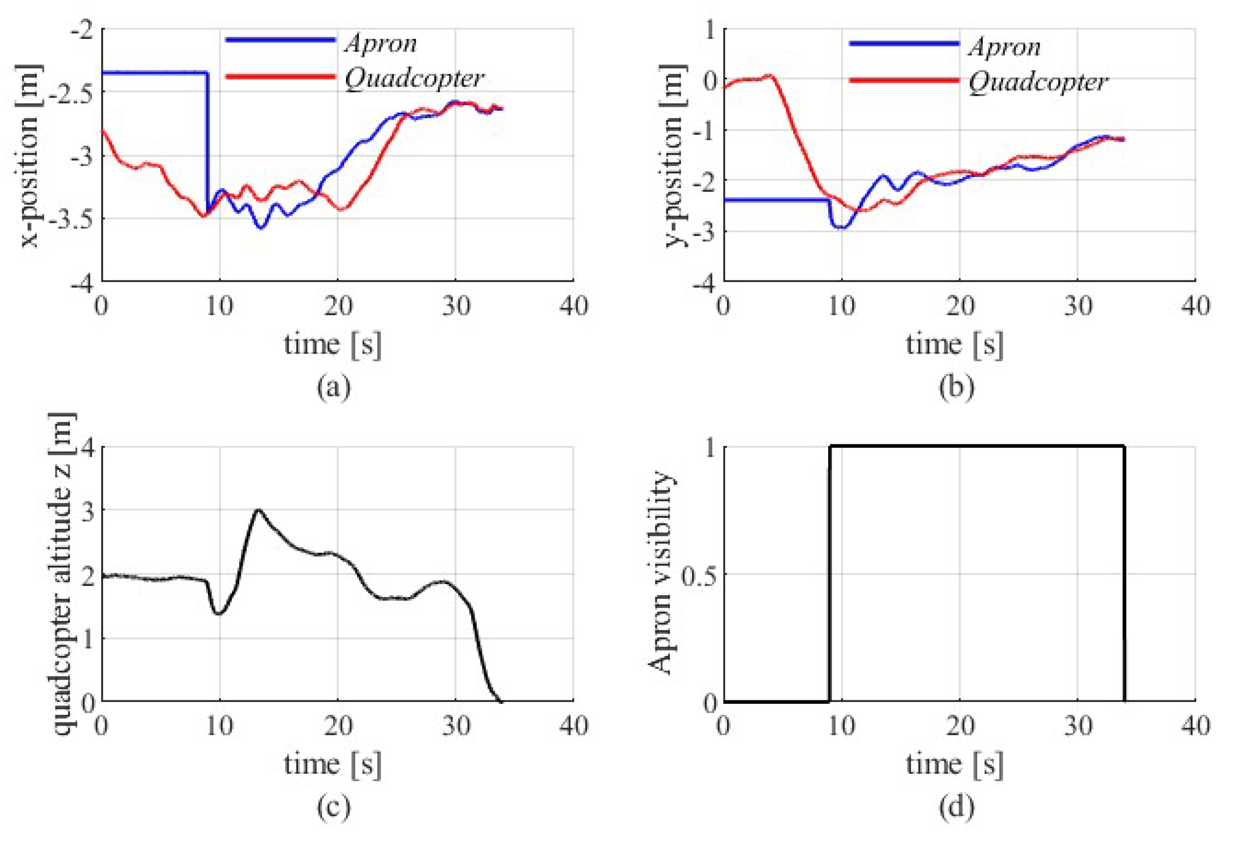
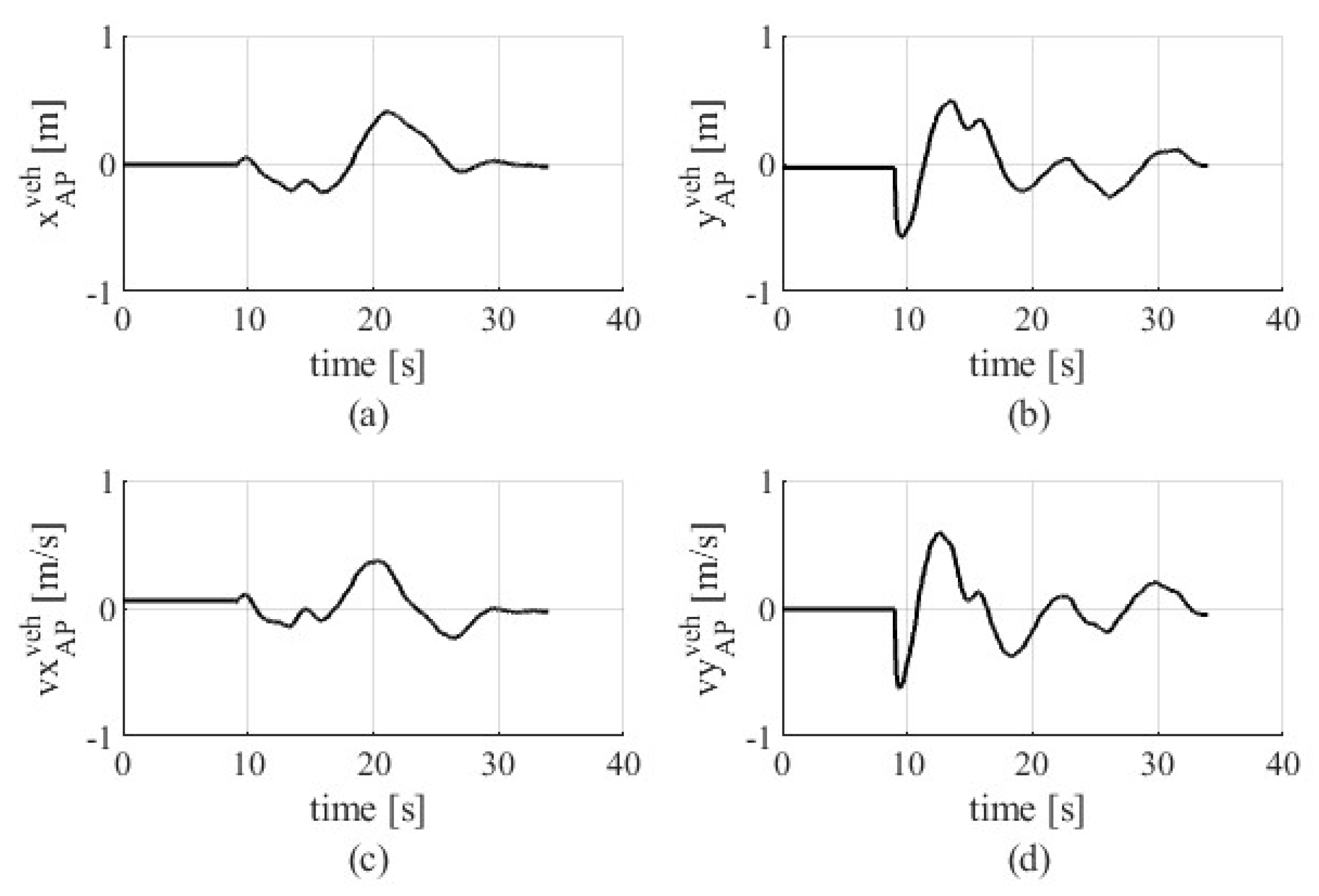
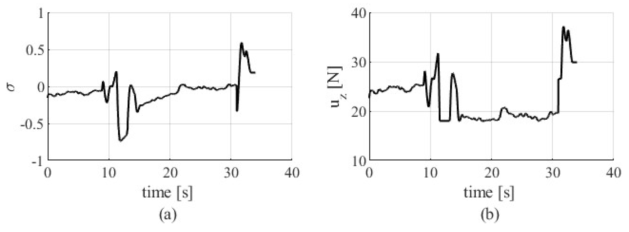
4.2. Experimental Results and Discussions

The experiment is conducted as follows: First, after taking-off, the vehicle climbs to reach an altitude of 2.0 m above the ground. Second, while the quadcopter is at a location away from the landing area (about 3 m), the autonomous landing is triggered. The vehicle starts moving horizontally toward the landing area based on GPS data. Afterward, it exhibits the precision landing procedure. A video of the demonstration can be found at https://youtu.be/0UYcAUZR-x8 (accessed on 13 April 2022).
To focus on the landing performance (Figure 7, Figure 8 and Figure 9), the flight data are shown from the landing-triggered time point. The experimental performance can be divided into two phases: (1) the GPS-based landing area approach and (2) the IR-camera-based precision landing.
The first phase is from t = 0 to t = 9 s (Figure 7a,b). In this phase, the vehicle horizontally approaches the landing area ( x = 3.2 m, y = 2.0 m in { E } ) from its current hovering location ( x = 2.8 m, y = 0.3 m in { E } ). The quadcopter’s altitude is maintained at 2.0 m while it is moving toward the landing area (Figure 7c). During this period, the IR camera is away from the apron, and as a result, it does not detect the IR beacon (Figure 7d).
From t = 9 s, as the quadcopter moves horizontally in the landing area and the beacon is detected (Figure 7d), the second stage begins. If we look at Figure 7c, it is seen that, as the camera detects the beacon, the quadcopter’s altitude measurement declines from 2.0 m to 1.5 m. This is because when the quadcopter is over the apron, this landing platform shortens the distance measured by the LidarLite range sensor. The altitude controller responds to this sudden change by lifting the vehicle up (from t = 10 s). Afterward, because the landing mission is still being undertaken, the altitude controller forces the vehicle to move down (until t = 28 s). During this period, the position controller continues to manipulate the quadcopter to horizontally come closer to the apron (Figure 7a,b). As the quadcopter and the apron are horizontally close, i.e., the horizontal distance between them is under a predefined threshold (0.15 m), the landing planner allows the vehicle to descend over the pad until the landing is completed.
The apron state estimation results (Figure 8) indicate that the proposed ASE works stably and reliably. In addition, the stability of our DOB altitude control algorithm is also validated as the σ converges to zero, and the control input u z remains stable and chattering free (Figure 9).

5. Conclusions

This paper presented a synthesized strategy for a quadcopter to land precisely on a vertical moving apron. The successful landing experiment clearly demonstrated the effectiveness, reliability, and applicability of our work. The IR Pixy camera and the proposed ASE enhance the target’s position determination and allow the vehicle to approach the target precisely. In addition, the proposed DOB altitude control algorithm enables the quadcopter’s ability to exhibit the landing mission stably and rapidly in actual flight conditions with many kinds of external disturbances. The landing planner delivered a safe and reliable autonomous landing. Our synthesized strategy is extensible and can be applied to real-world applications that require landing on a heaving vessel deck. Our future work is dedicated to the solution for the problem of precision landing on a three-dimensional moving apron.

Author Contributions

Conceptualization, N.X.M. and S.K.H.; methodology, N.X.M.; software, N.X.M.; validation, N.X.M., N.P.N., D.B.P. and N.N.D.; formal analysis, N.X.M.; investigation, N.X.M., N.P.N., D.B.P. and N.N.D.; resources, N.X.M.; data curation, N.X.M.; writing—original draft preparation, N.X.M.; writing—review and editing, N.X.M.; visualization, N.X.M.; supervision, N.X.M.; project administration, N.X.M.; funding acquisition, N.X.M. and S.K.H. All authors have read and agreed to the published version of the manuscript.

Funding

This research received no external funding.

Acknowledgments

This research was supported by the MSIT (Ministry of Science and ICT), Korea, under the ITRC (Information Technology Research Center) support program (IITP-2022-2018-0-01423) supervised by the IITP (Institute for Information & Communications Technology Planning & Evaluation) and was supported by Basic Science Research Program through the National Research Foundation of Korea (NRF) funded by the Ministry of Education (2020R1A6A1A03038540).

Conflicts of Interest

The authors declare no conflict of interest.

References

  1. Idrissi, M.; Salami, M.; Annaz, F. A Review of Quadrotor Unmanned Aerial Vehicles: Applications, Architectural Design and Control Algorithms. J. Intell. Robot. Syst. 2022, 104, 22. [Google Scholar] [CrossRef]
  2. Chamola, V.; Kotesh, P.; Agarwal, A.; Naren; Gupta, N.; Guizani, M. A Comprehensive Review of Unmanned Aerial Vehicle Attacks and Neutralization Techniques. Ad Hoc Netw. 2021, 111, 102324. [Google Scholar] [CrossRef] [PubMed]
  3. Xuan-Mung, N.; Hong, S.K. Robust backstepping trajectory tracking control of a quadrotor with input saturation via extended state observer. Appl. Sci. 2019, 9, 5184. [Google Scholar] [CrossRef] [Green Version]
  4. Pounds, P.E.; Bersak, D.R.; Dollar, A.M. Stability of small-scale UAV helicopters and quadrotors with added payload mass under PID control. Auton. Robot. 2012, 33, 129–142. [Google Scholar] [CrossRef]
  5. Nguyen, A.T.; Xuan-Mung, N.; Hong, S.K. Quadcopter adaptive trajectory tracking control: A new approach via backstepping technique. Appl. Sci. 2019, 9, 3873. [Google Scholar] [CrossRef] [Green Version]
  6. Ding, S.; Li, S. Second-order sliding mode controller design subject to mismatched term. Automatica 2017, 77, 388–392. [Google Scholar] [CrossRef]
  7. Wang, H.; Pan, Y.; Li, S.; Yu, H. Robust Sliding Mode Control for Robots Driven by Compliant Actuators. IEEE Trans. Control Syst. Technol. 2019, 27, 1259–1266. [Google Scholar] [CrossRef]
  8. Nguyen, N.P.; Mung, N.X.; Thanh, H.L.N.N.; Huynh, T.T.; Lam, N.T.; Hong, S.K. Adaptive Sliding Mode Control for Attitude and Altitude System of a Quadcopter UAV via Neural Network. IEEE Access 2021, 9, 40076–40085. [Google Scholar] [CrossRef]
  9. Ji, R.; Ma, J.; Ge, S.S. Modeling and Control of a Tilting Quadcopter. IEEE Trans. Aerosp. Electron. Syst. 2020, 56, 2823–2834. [Google Scholar] [CrossRef]
  10. Chang, X.H.; Liu, Y.; Shen, M. Resilient Control Design for Lateral Motion Regulation of Intelligent Vehicle. IEEE/ASME Trans. Mechatron. 2019, 24, 2488–2497. [Google Scholar] [CrossRef]
  11. Ho, H.W.; Croon, G.C.D.; Kampen, E.V.; Chu, Q.P.; Mulder, M. Adaptive Gain Control Strategy for Constant Optical Flow Divergence Landing. IEEE Trans. Robot. 2018, 34, 508–516. [Google Scholar] [CrossRef]
  12. Goncalves, V.M.; Mclaughlin, R.; Pereira, G.A. Precise Landing of Autonomous Aerial Vehicles Using Vector Fields. IEEE Robot. Autom. Lett. 2020, 5, 4337–4344. [Google Scholar] [CrossRef]
  13. Cabecinhas, D.; Naldi, R.; Silvestre, C.; Cunha, R.; Marconi, L. Robust Landing and Sliding Maneuver Hybrid Controller for a Quadrotor Vehicle. IEEE Trans. Control Syst. Technol. 2016, 24, 400–412. [Google Scholar] [CrossRef]
  14. Dougherty, J.A.; Lee, T. Monocular estimation of ground orientation for autonomous landing of a quadrotor. J. Guid. Control Dyn. 2016, 39, 1407–1416. [Google Scholar] [CrossRef]
  15. Hu, B.; Lu, L.; Mishra, S. A Control Architecture for Time-Optimal Landing of a Quadrotor Onto a Moving Platform. Asian J. Control 2018, 20, 1701–1712. [Google Scholar] [CrossRef]
  16. Ghommam, J.; Saad, M. Autonomous Landing of a Quadrotor on a Moving Platform. IEEE Trans. Aerosp. Electron. Syst. 2017, 53, 1504–1519. [Google Scholar] [CrossRef]
  17. Qi, Y.; Jiang, J.; Wu, J.; Wang, J.; Wang, C.; Shan, J. Autonomous landing solution of low-cost quadrotor on a moving platform. Robot. Auton. Syst. 2019, 119, 64–76. [Google Scholar] [CrossRef]
  18. Tzoumanikas, D.; Li, W.; Grimm, M.; Zhang, K.; Kovac, M.; Leutenegger, S. Fully autonomous micro air vehicle flight and landing on a moving target using visual–inertial estimation and model-predictive control. J. Field Robot. 2019, 36, 49–77. [Google Scholar] [CrossRef] [Green Version]
  19. Liu, X.; Zhang, S.; Tian, J.; Liu, L. An onboard vision-based system for autonomous landing of a low-cost quadrotor on a novel landing pad. Sensors 2019, 19, 4703. [Google Scholar] [CrossRef] [Green Version]
  20. Araar, O.; Aouf, N.; Vitanov, I. Vision Based Autonomous Landing of Multirotor UAV on Moving Platform. J. Intell. Robot. Syst. Theory Appl. 2017, 85, 369–384. [Google Scholar] [CrossRef]
  21. Borowczyk, A.; Nguyen, D.T.; Nguyen, A.P.V.; Nguyen, D.Q.; Saussié, D.; Ny, J.L. Autonomous Landing of a Multirotor Micro Air Vehicle on a High Velocity Ground Vehicle. Ifac-Papersonline 2017, 50, 10488–10494. [Google Scholar] [CrossRef]
  22. Tan, C.K.; Wang, J.L.; Paw, Y.C.; Liao, F. Robust linear output feedback controller for autonomous landing of a quadrotor on a ship deck. Int. J. Control 2019, 92, 2791–2805. [Google Scholar] [CrossRef]
  23. Tan, L.; Wu, J.; Yang, X.; Song, S. Research on optimal landing trajectory planning method between an UAV and a moving vessel. Appl. Sci. 2019, 9, 3708. [Google Scholar] [CrossRef] [Green Version]
  24. Huang, Y.; Zheng, Z.; Sun, L.; Zhu, M. Saturated adaptive sliding mode control for autonomous vessel landing of a quadrotor. IET Control Theory Appl. 2018, 12, 1830–1842. [Google Scholar] [CrossRef]
  25. Lu, Q.; Ren, B.; Parameswaran, S. Shipboard landing control enabled by an uncertainty and disturbance estimator. J. Guid. Control Dyn. 2018, 41, 1502–1520. [Google Scholar] [CrossRef]
  26. Tan, C.K.; Wang, J.; Paw, Y.C.; Liao, F. Autonomous ship deck landing of a quadrotor using invariant ellipsoid method. IEEE Trans. Aerosp. Electron. Syst. 2016, 52, 891–903. [Google Scholar] [CrossRef]
  27. Wang, L.; Bai, X. Quadrotor Autonomous Approaching and Landing on a Vessel Deck. J. Intell. Robot. Syst. Theory Appl. 2018, 92, 125–143. [Google Scholar] [CrossRef]
  28. Lee, J.W.; Xuan-Mung, N.; Nguyen, N.P.; Hong, S.K. Adaptive altitude flight control of quadcopter under ground effect and time-varying load: Theory and experiments (Early access). JVC/J. Vib. Control 2021. [Google Scholar] [CrossRef]
  29. Xuan-Mung, N.; Hong, S.K. Barometric Altitude Measurement Fault Diagnosis for the Improvement of Quadcopter Altitude Control. In Proceedings of the 2019 19th International Conference on Control, Automation and Systems (ICCAS), Jeju, Korea, 15–18 October 2019; Volume 2019. [Google Scholar] [CrossRef]
  30. Do, K.D.; Pan, J. Nonlinear control of an active heave compensation system. Ocean Eng. 2008, 35, 558–571. [Google Scholar] [CrossRef] [Green Version]
  31. Khalil, H. Nonlinear Systems, 3rd ed.; Prentice Hall: Upper Saddle River, NJ, USA, 2002. [Google Scholar]
  32. Kim, P. Kalman Filter for Beginners with Matlab Examples; A-JIN Publishing Company: Seoul, Korea, 2010. [Google Scholar]
  33. CMUcam5 Pixy. Available online: http://www.cmucam.org/projects/cmucam5 (accessed on 13 April 2022).
  34. Odroid XU4 User Manual. Available online: https://magazine.odroid.com/wp-content/uploads/odroid-xu4-user-manual.pdf (accessed on 13 April 2022).
  35. Arduino Uno Rev3. Available online: https://store-usa.arduino.cc/products/arduino-uno-rev3 (accessed on 13 April 2022).
Figure 1. A typical quadcopter configuration.
Mathematics 10 01328 g001
Figure 2. The position of the apron image in the camera-sensor-fixed coordinate ( { C } ) and the apron position in the quadcopter’s body-fixed coordinate ( { B } ).
Mathematics 10 01328 g002
Figure 3. The apron position in the quadcopter’s body-fixed coordinate ( { B } ) and in the local earth-fixed coordinate ( { E } ).
Mathematics 10 01328 g003
Figure 4. The experimental quadcopter platform and its equipped devices.
Mathematics 10 01328 g004
Figure 5. Block diagram of the system signal flow.
Mathematics 10 01328 g005
Figure 6. The apron is used to simulate a heaving vessel deck.
Mathematics 10 01328 g006
Figure 7. Landing target approaching control performance, including (a,b) the positions and (c) the altitude of the quadcopter and (d) the visibility of the apron.
Mathematics 10 01328 g007
Figure 8. The apron state estimation results, including (a,b) the relative position and (c,d) the relative velocity of the apron in { B } .
Mathematics 10 01328 g008
Figure 9. (a) The variable σ and (b) the control input ( u z ) performance of the proposed DOB altitude controller.
Mathematics 10 01328 g009
Table 1. Comparing our proposed work and the most related work in the literature [27].
Comparison Criteria[27]Our WorkMerit
Landing (altitude) controllerPIDProposed DOB controllerImproved Reliability
Our solution is theoretically and practically reliable for quadcopter landing on ship decks in the presence of significant external disturbances.
Emulator stroke (heaving amplitude of landing platform)6 cm30 cmHigher Realism
The large stroke of our emulator provides a more realistic approximation of the ship deck’s vertical motion, thus ensuring that our work can be directly applied to real-world applications.
Camera systemVisual spectrum cameraIR cameraMultifunction
Our approach remains functional even in dark or low-light environments.
Number of beacons41Simplicity
Requiring only one landing beacon, our system can be quickly and easily installed on any landing platform.
Table 2. The parameters of the quadcopter dynamics and pixy camera’s FOV.
SymbolValueUnit
m 2.71 kg
J x ,   J y ,   J z 0.0172 ,   0.0143 ,   0.0221 kg·m 2
L 0.225 m
g 9.81 m/s 2
α x ,   α y 60 ,   47 deg
Table 3. Parameters of the apron.
ParameterValueUnit
Length × Width 1.05 × 0.85 m
Height 0.45 0.75 m
Vertical stroke300mm
Vertical speed90mm/s
Table 4. Controller gains, observer gains, and camera data sampling time used in the experiment.
SymbolValue and UnitDescription
K 0.85 Controller gain
Λ 10.47 Controller gain
Γ 1.6 Observer gain
t s 0.02 sSampling time
Publisher’s Note: MDPI stays neutral with regard to jurisdictional claims in published maps and institutional affiliations.

