Article

An Optimal H-Infinity Controller for Left Ventricular Assist Devices Based on a Starling-like Controller: A Simulation Study

1
Department of Medical Equipment Technology, College of Applied Medical Science, Majmaah University, Al Majma’ah City 11952, Saudi Arabia
2
Department of Physics, College of Arts, Fezzan University, Traghen 71340, Libya
3
Department of Zoology, College of Arts, Fezzan University, Traghen 71340, Libya
4
Department of Biomedical Equipment Technology, Inaya Medical College, Riyadh City 13541, Saudi Arabia
5
Department of Electrical Engineering, College of Engineering, Tripoli University, Tripoli 22131, Libya
6
Biomedical Engineering Department, College of Engineering, Imam Abdulrahman Bin Faisal University, Dammam 31441, Saudi Arabia
*
Authors to whom correspondence should be addressed.
Mathematics 2022, 10(5), 731; https://doi.org/10.3390/math10050731
Submission received: 29 January 2022 / Revised: 17 February 2022 / Accepted: 24 February 2022 / Published: 25 February 2022

Abstract

:
Left ventricular assist devices (LVADs) are emerging innovations that provide a feasible alternative treatment for heart failure (HF) patients to enhance their quality of life. In this work, a novel physiological control system to optimize LVAD pump speed using an H-infinity controller was developed. The controller regulates the calculated target pump flow vs. measured pump flow to meet the changes in metabolic demand. The method proposes the implementation of the Frank–Starling mechanism (FSM) approach to control the speed of an LVAD using the left ventricle end-diastolic volume (Vlved) parameter (preload). An operating point was proposed to move between different control lines within the safe area to achieve the FSM. A proportional–integral (PI) controller was used to control the gradient angle between control lines to obtain the flow target. A lumped parameter model of the cardiovascular system was used to evaluate the proposed method. Exercise and rest scenarios were assessed under multi-physiological conditions of HF patients. Simulation results demonstrated that the control system was stable and feasible under different physiological states of the cardiovascular system (CVS). In addition, the proposed controller was able to keep hemodynamic variables within an acceptable range of the mean pump flow (Qp) (max = 5.2 L/min and min = 3.2 L/min) during test conditions.

1. Introduction

A patient with heart failure (HF) may have difficulty continuing the heart cycle due to the prevention of or reduced blood flow to the heart. HF may affect the right or left side of the heart, or both. This could be a chronic (persistent) or severe (short-term) disease. Several causes, including coronary artery disease, congenital disabilities, excessive high blood pressure, heart attacks, and valve disorders, usually cause HF [1]. The most severe form of heart disease is congestive HF, which can cause pulmonary edema, while less common HF can cause peripheral edema. Despite the spread of this disease in several countries, medical treatment is well established in this field. Improving the quality of life for those who suffer from the disease remains a difficult challenge [2,3].
Although medical HF management has been enhanced, cardiac transplantation remains the best treatment for HF at the end stage. Nevertheless, the lack of transplantation donor hearts, drug limitations, and surgical procedures have aided in implementing numerous schemes of mechanical support for the most seriously ill HF patients [4]. Left ventricular assist devices (LVADs), known as implantable rotary blood pumps (IRBPs), can turn into a viable long-term alternative for the bridging of cardiac transplants or indefinite assistance (destination therapy). The third generation of the ventricular assist device (VAD) can offer a valuable solution, due to its ability to perform long-term functions in working conditions compatible with human body physiology. Compact sizes and light weights are the key features of the design that make it secure for patients. It improves patients’ ability to leave the hospital and return to a healthy life [5].
VADs, including both the pulsatile flow (PF) and the continuous flow (CF) (or IRBPs), are mechanical pump systems used to replace the HF function as a whole or partially. Generally, VADs are used for limited periods, particularly in patients with transplant bridges or a cardiovascular recovery; other medications are intended for high or long-term implantation in patients with HF. Supporting systems may be either LVAD or a right ventricular assistance device (RVAD) or both bi-ventricular (BiVAD) at the same time. BiVAD support systems could be pneumatic and pulsatory extracorporeal devices. Technically, these devices are so well designed to achieve clinical application. The third generation of VADs involve continuous flow rotor pumps that use a rotating pump to transmit flow and blood pressure. These VADs are fully levitating, rotating without mechanical contact, hydrodynamic bearings, magnetic layers, or combinations of the two [6,7].
VAD is a pump that helps the heart maintain blood flow from the weak left ventricle (LV) to the aorta. The VAD characteristic response to hydrodynamic load changes contradicts the body’s requirements [6]. The pumps steadily decrease pressure and flow difference, and the body needs more fluid to increase the pressure. The operating speed of the VAD should, therefore, be adjusted to satisfy the physiological demand of a patient based on a changing preload and afterload [8]. However, hemolysis induction, thrombus, and tissue damage at the VAD induction may occur in the LV at relatively high LVAD rates of operation. Therefore, any control strategy should be able to regulate the flow through the VAD. A feedback control method is usually used to adjust the current signal (pulse-width modulation signal) and then flow signals according to the patient’s activity. This scenario depends on multiple parameters leading from increasing or decreasing the current supply, which monitors the flow of blood and adjusts it according to the requirements [9,10].
In VAD pumps, there is only one control input, which is the pump speed, and only one control output, which is the pump flow rate. However, IRBPs are required for meeting various medical demands (control objectives), such as:
  • Maintaining the circulation of a patient with HF.
  • Controlling the flow rate to meet the changes in metabolic demand.
  • Making a physiological flow pattern (pulsatile flow).
  • Unloading the left ventricle.
  • Preventing inflow suction.
  • Preventing aortic valve insufficiency.
Therefore, the pump speed is controlled by various control methods (VAD control) based on multiple input information (VAD variables) to meet these demands. Based on this concept, several physiological regulation control methods for VAD were proposed and validated in different clinical conditions. These include the flow rate control [11,12], pump differential pressure [13], aortic pressure [14], pulsatility index [15] or heart rate regulation [16], suction limit control [17], and aortic valve function [18]. On the other hand, controlling VAD pumps requires continuous flow and pressure sensors. However, using pressure and flow sensors increases the complexity of implementation, due to the need for periodic calibration, which minimizes battery life and decreases overall device reliability [10].
Several research groups were developed, and they implemented sensorless approaches to estimate the flow and differential pressure [19,20,21]. Nevertheless, after a closer analysis of these approaches, it was evident that some pumps’ features lead to significant differences among the estimator algorithms proposed empirically and, probably, to each pump design. As a result, suction or overperfusion may occur at any time of work operation for VAD pumps [10]. Therefore, to solve this issue, suction limit control was proposed to solve the challenges under perfusion caused by a low set-point value for the flow [22,23]. Suction limit control maximizes the perfusion by operating the pump at the most significant possible speed before suction. However, because the region of suction start is often limited, ventricular suction occurs frequently in response to a decrease in preload. Additionally, this control strategy may expose the patient to an increased risk of over-perfusion due to the difficulties in detecting the over-perfusion or suction [24]. A physiological controller for VADs means a variable speed control of the VAD pump based on the physiological demand of HF patients. However, this kind of VAD control remains a significant challenge [8,25]. Therefore, to achieve this goal, it is essential to implement the principle of the Frank–Starling mechanism (FSM). In recent work, Bakouri et al. [12] presented a clinically intuitive Starling-like controller for pump flow that mimics the heart’s Frank–Starling law—the LV outflow decreases as the preload, i.e., the LV filling pressure, increases.
The current study presents an advanced physiological control method that utilizes the sensorless estimator to estimate the pump flow. The objective of this controller is to emulate FSM by controlling the operating point through the preload control lines within the safe zone to prevent suction and over-prefusion. Furthermore, an optimal H-infinity control method is proposed to adopt the physiological requirements for an LVAD. To our knowledge, this is the first study in which an H-infinity controller is employed to control an LVAD.

2. Materials and Methods

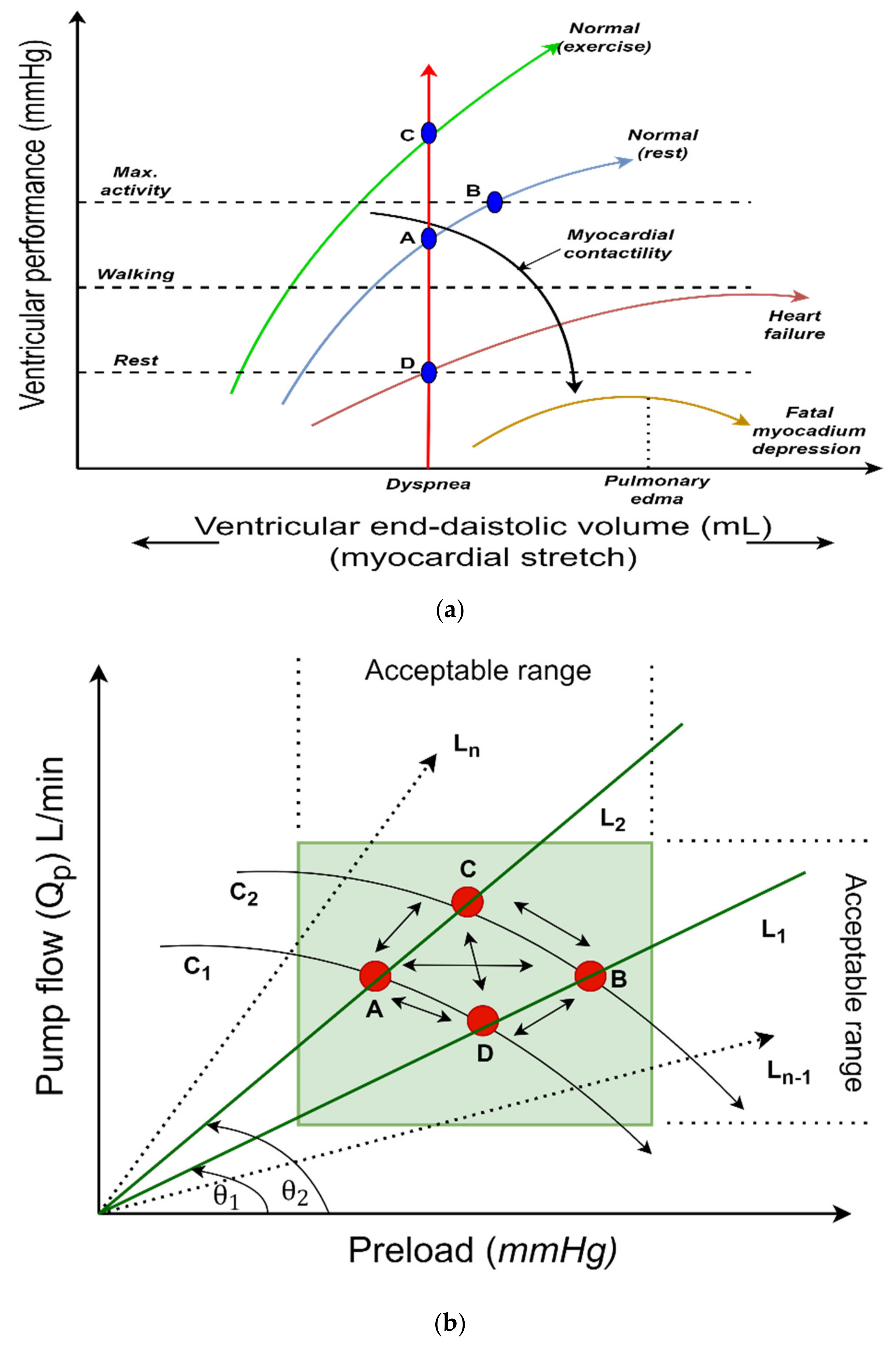
2.1. Control Strategy

In general, Starling’s law of the heart states that increasing ventricular filling pressure (or preload) increases stroke volume or cardiac output. As a result, variations in myocardial contractility can be achieved at any given filling pressure for the heart or by the decrease in contractility, which results in a reduction in the output and vice versa, as shown in Figure 1a. It has been well established through studies in the literature and animal experimental results that the pump flow pulsatility is dependent on the LV filling pressure. Therefore, we used this dependency to implement a control method to drive the VAD pump [26,27].
Figure 1b depicts the operation mechanism of a Starling-like controller. In this mechanism, the system operating point is defined as the point at which the target flow preload line intersects with the system flow preload curve (denoted by the letter ‘C’ in Figure 1b). This mechanism is formed by altering the LVAD speed at any given instant in time. As a result, pump flow pulsatility decreases, and the pump flow increases when the LVAD speed is increased. However, reducing the LVAD speed provides the inverse response when the LVAD speed is decreased. In addition, circulatory circumstances influence the system flow preload curve. For example, increasing the total circulatory volume causes the flow preload curve in the system to move to the right (from C1 to C2, as illustrated in Figure 1b).

2.2. Pump Flow Estimator Model

A pump flow estimator model was developed and validated by our research group to estimate the mean pump flow of an LVAD [28]. Two dynamical time variant single-input single-output autoregressive models with exogenous input (ARX) were used as a series connection to achieve this object. In the first ARX model, the pulse-width modulation signal ( P W M ) was used to estimate the pulsatility index of the pump rotational speed ( P I ω ) as:
ξ 1 ( n + 1 ) + i = 1 k a i ( n i + 1 ) ξ 1 ( n i + 1 ) = j = 1 m b j ( n j + 1 ) u ( n j l + 1 ) + e 1 ( n )
Here, ξ 1 ( n ) is the P I ω , u ( n ) is the P W M , a ( n ) and b ( n ) are the output and input time varying system parameters, respectively; e 1 ( n ) is the model noise, l is the delay value, n is the sampling time, and k and m are the model output and input orders, respectively.
The output of the first ARX model was used as the input to the second ARX model to estimate the pulsatile flow ( Q p ) as:
ξ 2 ( n + 1 ) + i = 1 k c i ( n i + 1 ) ξ 2 ( n i + 1 ) = j = 1 m d j ( n j + 1 ) ξ 1 ( n j q + 1 ) + e 2 ( n )
Here, ξ 2 ( n ) is the estimated Q p , and c ( n ) and d ( n ) are the output and input time varying system parameters, respectively; e 2 ( n ) is the model noise and q is the delay value.
In both models, a recursive least square method was used to estimate the model parameters of the system. The resulting dynamical estimator model can be given as:
ξ ( n + 1 ) = A ξ ( n ) + B u ( n ) + μ ( n ) Q p ( n ) = C ξ ( n ) + D u ( n )
where ξ ( n ) is the states of model estimator, u ( n ) is the pump control input, which is the pulse width modulation, P W M , μ ( n ) is the process noise, Q p is the system output, and A ,   B ,   C and D are the model matrices.

2.3. Controller Design

This work aimed to design an automatic controller by changing the control output based on the difference between a given point and a measured process variable. Thus, the device output value is transmitted as the system input. In particular, an optimal H-infinity controller was used to drive the LVAD by regulating the target pump flow and measuring the pump flow for each cardiac cycle [29]. Figure 2 depicts the proposed control system to obtain a Starling-like controller. In this Figure, the gradient angle (θ) is calculated using a proportional–integral (PI) controller. As a result, the angle automatically adjusts the pump flow within the corresponding upper or lower limits (green square). Therefore, this angle can be calculated as:
θ = k p , θ ( e Q p + e P I Q p ) + k i , θ ( e Q p + e P I Q p )
where k p , θ is the proportional gain and k i , θ is the integral gain. Therefore, the target pump flow ( Q t ) can be calculated based on θ as:
Q t = P I Q P tan ( θ )
where P I Q P is the pulsatility of the pump flow. If either the pump flow or pump flow pulsatility lie outside their corresponding upper or lower limits, the gradient angle ( θ ) is automatically modified using the PI controller to adjust the pump flow or pump flow pulsatility back to their corresponding upper or lower limits.
In this method, an H-infinity controller was proposed to robustly drive the LVAD pump. Therefore, the model in Equation (1) is linearized by the fractional transformations method as:
ξ ( n + 1 ) = A ξ ( n ) + B 1 δ ( n ) + B 2 u ( n ) η ( n ) = C 1 ξ ( n ) + D 11 δ ( n ) + D 12 u ( n ) Q ( n ) = C 2 ξ ( n ) + D 21 δ ( n ) + D 22 u ( n )
In terms of the input and output vectors, the P ( s ) , which represent the interconnected system, can be written as:
η ( n ) = P η δ δ ( n ) + P η u u ( n ) Q ( n ) = P Q δ δ ( n ) + P Q u u ( n )
where η is the regulated output that needs to be minimized and δ is the exogenous input. Thus, we can write the pump control input as:
u ( n ) = K Q ( n )
as a result, it is feasible to represent the dependency of η on δ as:
η ( n ) = Τ η δ δ ( n )
where Τ η δ is known as the lower linear fractional transformation and given by:
Τ η δ = P η δ + P δ u K ( 1 P Q u K ) 1 P Q δ
Here, we need to minimize Τ η δ in accordance with the infinity norm to find the controller, K ( s ) ; therefore, we can write:
Τ η δ = sup ω σ ˜ Τ η δ j ω
Therefore, the controller, K ( s ) , is only be stabilizable for the P ( s ) if and only if the infinity norm of the closed transfer function, Τ η δ , is less than a specified level ( λ = positive scalar):
M i n Τ η δ λ
To obtain K ( s ) , the system used weighting matrices of controller gain ( K c ) and estimator gain ( K e ) as a pert from the solution of two algebraic Riccati equations:
K c = D 12 D 12 1 B 2 ψ + D 12 C 1
K e = D 12 D 21 1 C 2 Ω + D 21 B 1
where ψ and Ω are the positive semi-definite solutions to the Riccati equations for the controller and estimator, respectively:
ψ = R i c A B 2 ( D 12 D 12 ) 1 D 12 C 1 λ 2 B 1 B 1 B 2 ( D 12 D 12 ) 1 B 2 C ˜ 1 C ˜ 1 A B 2 ( D 12 D 12 ) 1 D 12 C 1
Here, C ˜ 1 = 1 D 12 ( D 12 D 12 ) 1 D 12 C 1
Ω = R i c A B 1 ( D 21 D 21 ) 1 D 21 C 2 λ 2 C 1 C 1 C 2 ( D 21 D 21 ) 1 C 2 B ˜ 1 B ˜ 1 A B 1 ( D 21 D 21 ) 1 D 21 C 2
Here, B ˜ 1 = B 1 1 D 21 ( D 21 D 21 ) 1 D 21 .
It is necessary that positive semidefinite solutions to the two Riccati equations satisfy the spectral radius criteria given below, in order to be used as a stabilizing compensator. Therefore, we can write:
ρ ψ Ω < λ 2
Thus the compensator model is given by:
ξ n + 1 = A ξ ( n ) + B 2 u ( n ) + B 1 δ ( n ) + η ( n ) K e ( Q ( n ) Q ( n ) )
Here, Q ( n ) = C 2 ξ ( n ) + ( λ 2 D 21 B 1 ψ ) ξ ( n ) , δ ( n ) = ( λ 2 B 1 ψ ) ξ ( n ) , η ( n ) = ( 1 λ 2 Ω ψ ) 1 and u ( n ) = K c ξ ( n ) , where u , ξ , δ , and Q are the control inputs to the plant, estimated states, estimated exogenous inputs, and estimated measured outputs, respectively.
Therefore, the controller matrix K ( s ) is written as:
K ( s ) = A B 2 K c η ( n ) K e C 2 + λ 2 ( B 1 B 1 η ( n ) K e D 21 B 1 ) ψ η ( n ) K e K c 0
and the state space of the closed loop system can be written as:
ξ ( n + 1 ) ξ ( n + 1 ) = A B 2 K c η ( n ) K e C 2 A B 2 K c + λ 2 B 1 B 1 ψ η ( n ) K e ( C e + λ 2 D 21 B 1 ψ ) ξ ( n ) ξ ( n ) + B 1 η ( n ) K e D 21 δ ( n )
η ( n ) Q ( n ) = C 1 D 12 K c C 2 0 ξ ( n ) ξ ( n ) + 0 D 21 δ ( n )

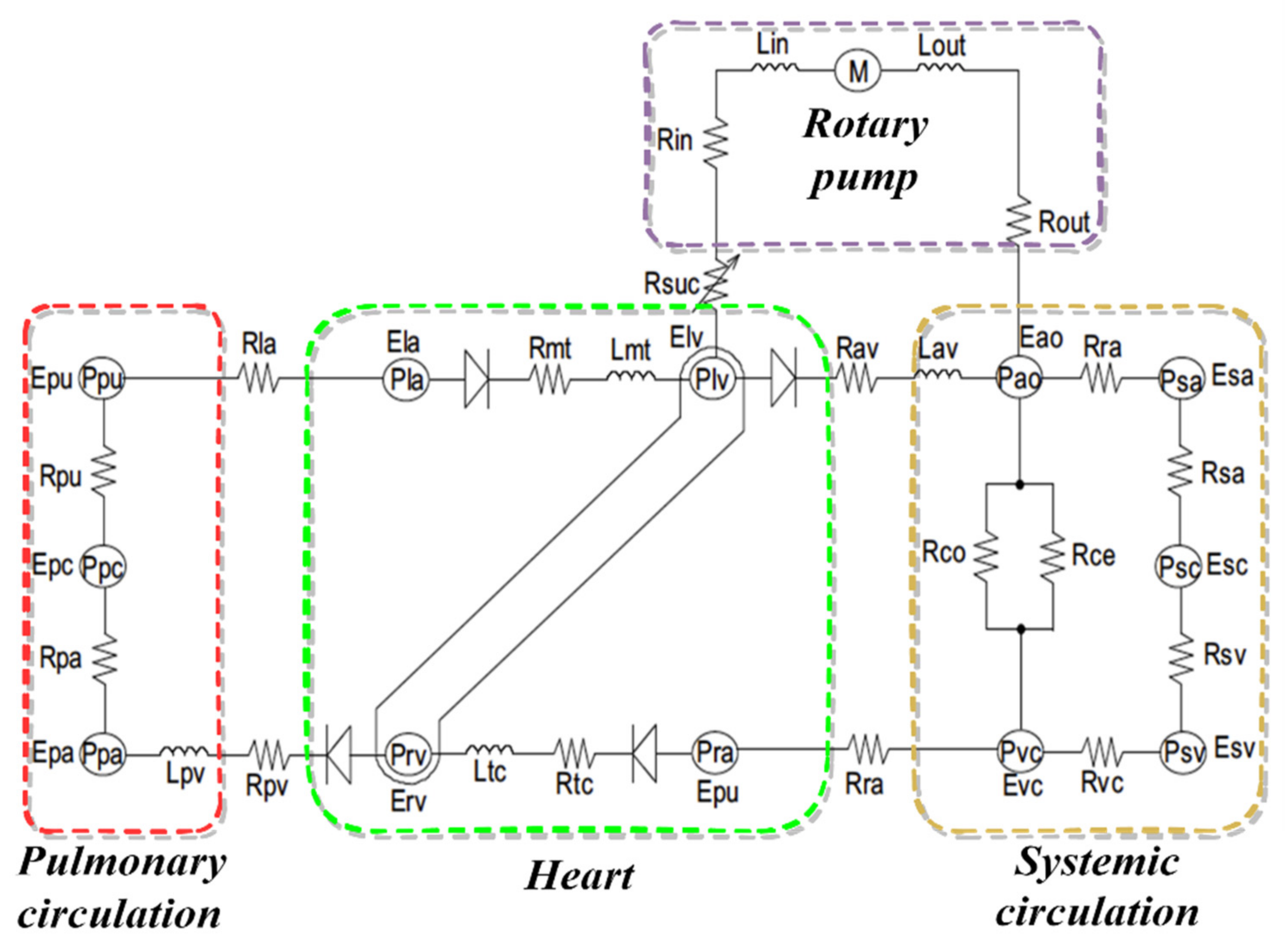
2.4. Cardiovascular System Model

This work was evaluated using a lumped parameter model of the cardiovascular system (CVS) that our research group developed. The model was implemented by incorporating a dynamic heart (left and right hearts, systemic, and pulmonary circulations) with an LVAD pump, as shown in Figure 3. The model was implemented and validated using experimental data collected from five greyhounds. The dogs were implanted with LVADs under various operational settings in this model. This included changes in the total circulatory, systemic vascular resistance, and cardiac contractility.
The pressure–volume characteristics of the CVS hemodynamic model can be mathematically described as:
(a)
Blood vessel compartment ( V k ):
V k = D k D u , k C k
where k represents one of the following:
Pulmonary peripheral vessel (pa);
Pulmonary veins (pvs);
Vena cava (vc);
Aorta (ao);
Systemic veins (svs);
Systemic peripheral vessel (sa).
D u , k is the unstressed volume of the corresponding vessel and C k is the compliance of the corresponding vessel.
(b)
Blood flow across the valves ( Q k ):
Q k = P k P k + 1 R k P k P k + 1 0 P k < P k + 1
where k represents one of the following:
Mitral valve (mt);
Tricuspid valve (tv);
Aortic valve (av);
Pulmonary valve (pv).
P k is the upstream pressure, P k + 1 is the downstream pressure of the corresponding valve, and R k is the resistance of the corresponding valve.
(c)
Pressure in the heart chamber ( P i )
P i = e v ( t ) E e s , k ( V k V s , k ) + ( 1 e v ( t ) ) P 0 , k ( e λ k ( V k V d , k ) 1 )
where k represents one of the following:
Left ventricular (lv);
Right ventricular (rv);
Left atrium (la);
Right atrium (ra).
E e s , n is the slope of the end-systolic pressure–volume, V k is the volume of the heart chamber, V s , k is the end-systolic volume of the heart chamber at zero pressure, V d , k is the end-diastolic volume of the heart chamber at zero pressure, and P 0 , k , λ k are the stiffness of the heart chamber at the end diastolic.
In this model, the steady resistance for inlet ( R i n ) and outlet ( R o u t ) cannulas was modeled to create stress, whereas the steady inductance for inlet ( L i n ) and outlet ( L o u t ) cannulas was modeled to create the flow rate modifications. A suction resistance ( R s u c ) was used before the intake cannula to simulate suction occurrences. The validation of this model is accomplished in both healthy and HF patients and the full details on the system model and validation can be found in [30]. Table A1 in Appendix A illustrates all nomenclature for the CVS, estimator model, and designed controller.

2.5. Simulation Protocols

The control method and CVS model were developed in MATLAB (MathWorks, Inc., Natick, MA, USA), including an ordinary differential equation (ODE) solver package. Table 1 illustrates the CVS model parameters at healthy and HF conditions that are used as the baseline during simulations. Two simulation scenarios were proposed and conducted to evaluate the control method in response to CVS parameters for the total period of 60 s. In the first scenario (rest scenario or blood loss), the total blood volume (Vtotal) was reduced by 500 mL at 30 s and the system parameters were kept to complete the cardiac cycle. This simulation is obtained to assess the quick responsiveness of the controller to change the speed for the LVAD to provide initial support for the patient under HF conditions. For the exercise scenario, the controller was evaluated under severe HF conditions by changing the system parameters of CVS for 30 s. To achieve this scenario, left ventricular contractility (Elv) and right ventricular contractility (Erv) were linearly increased by 20% and the systemic peripheral resistance (Rsa) was decreased by 50%. This simulation aims to evaluate the controller responses to the circulatory perturbations (via a change in the controller gradient).

3. Results

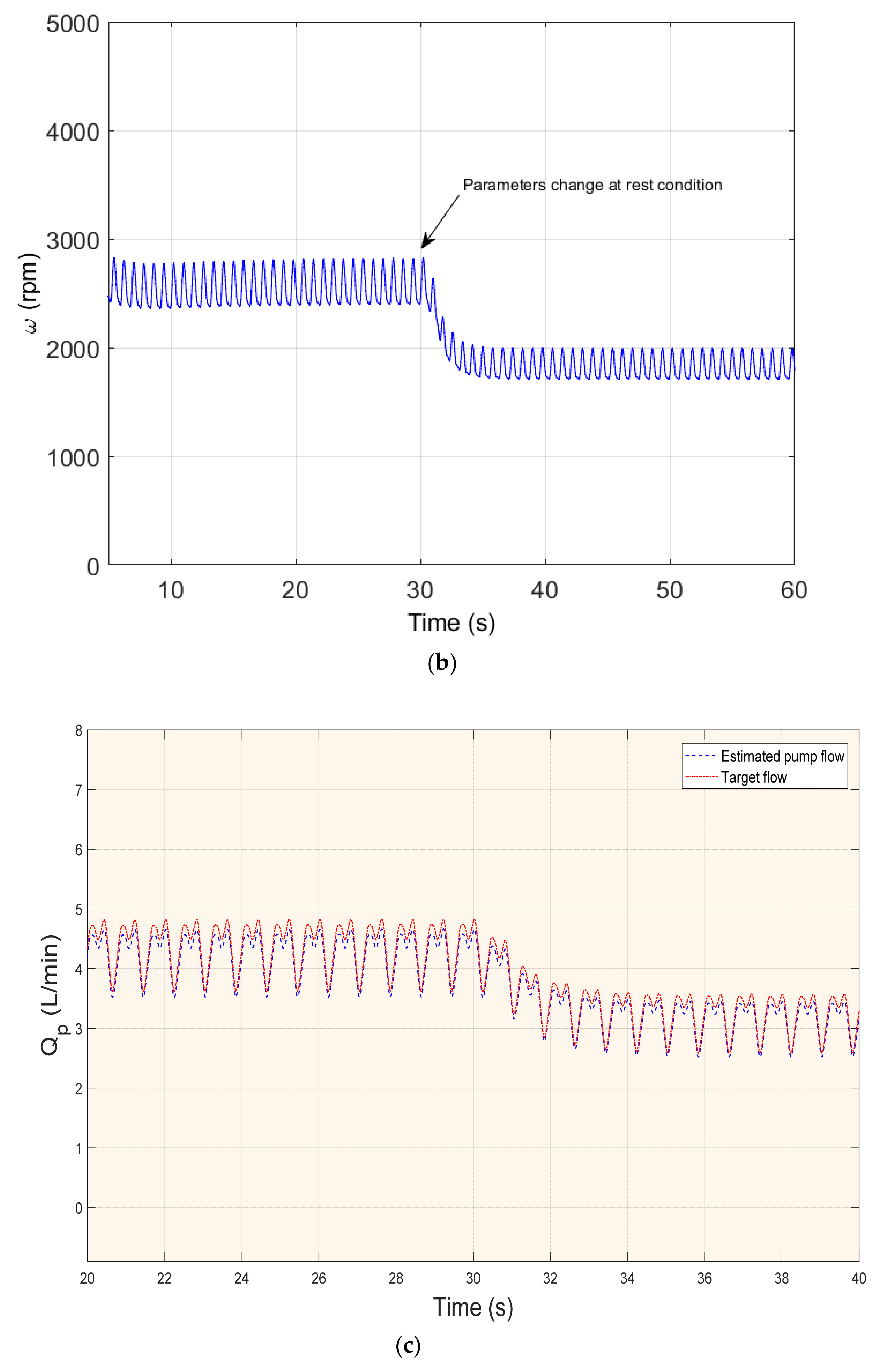
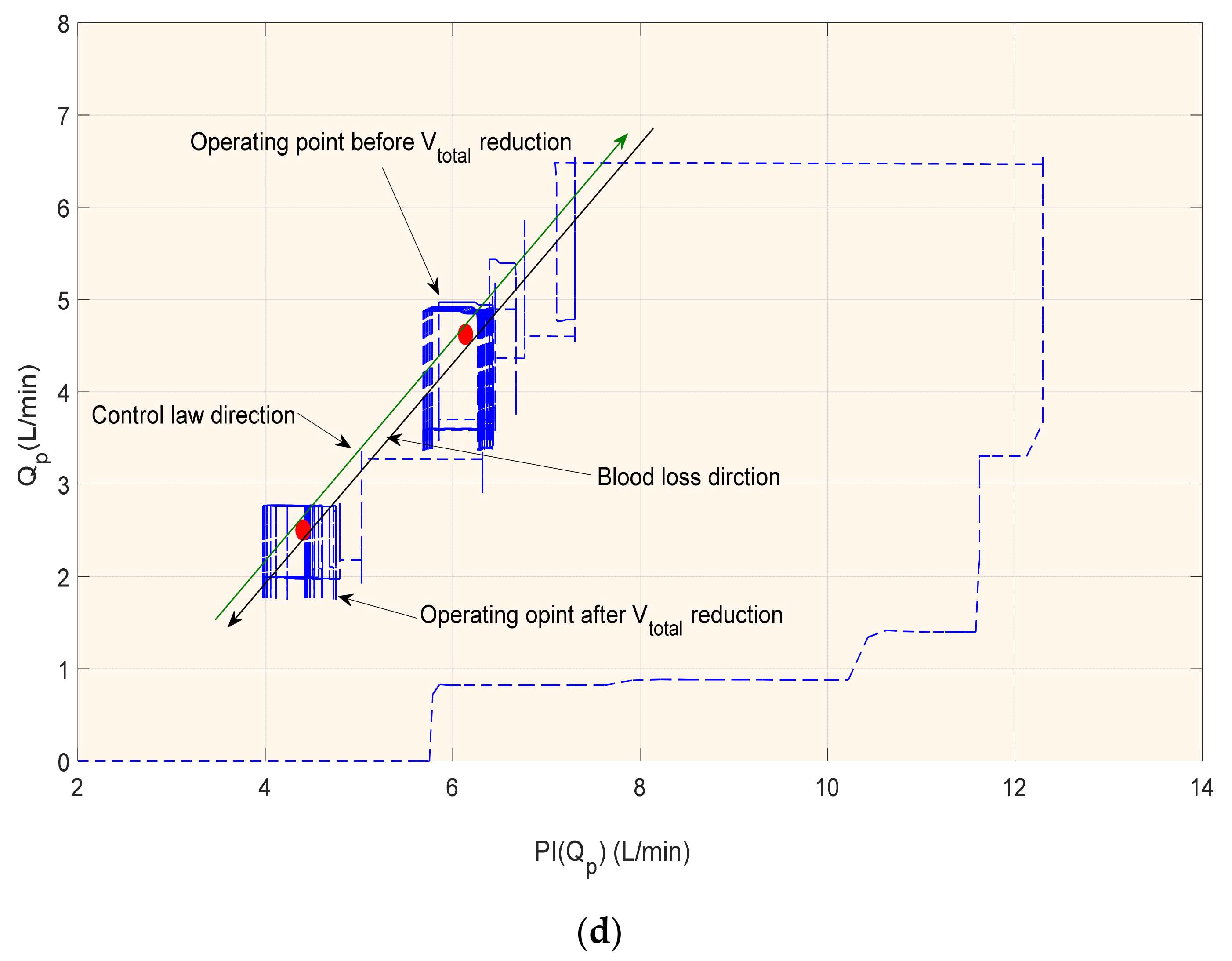
3.1. Rest Scenario or Blood Loss

In this scenario, the system parameters were changed by reducing Vtotal with 500 mL at 30 s. It resulted in the slight movement of LV and RV pressure–volume loops (Stroke work, SW) to the left, as shown in Figure 4a. Consequently, the LV and RV end-diastolic and end-systolic volumes (Vlved, Vrved) and pressures (Plved, Prved) were decreased. Therefore, the controller was quick in its response to change the average pump speed (ω) from 2850 rpm to 1950 rpm, as shown in Figure 4b, and then change the pump flow (Qp) from 4 L/min to 3.1 L/min as shown in Figure 4c.
In the rest scenario, the sudden drop in LVAD flow resulted in changes to the flow pulsatility and, therefore, movement of the operating point down and to the left along with the target preload flow line. When the pump flow drops below the minimum 3 L/min, the controller switches to a new control line with a new upper steeper slope (k = 1.5) in order to increase the average pump flow. After this increase in flow, the operating point immediately settles to the new line, as shown in Figure 4d.

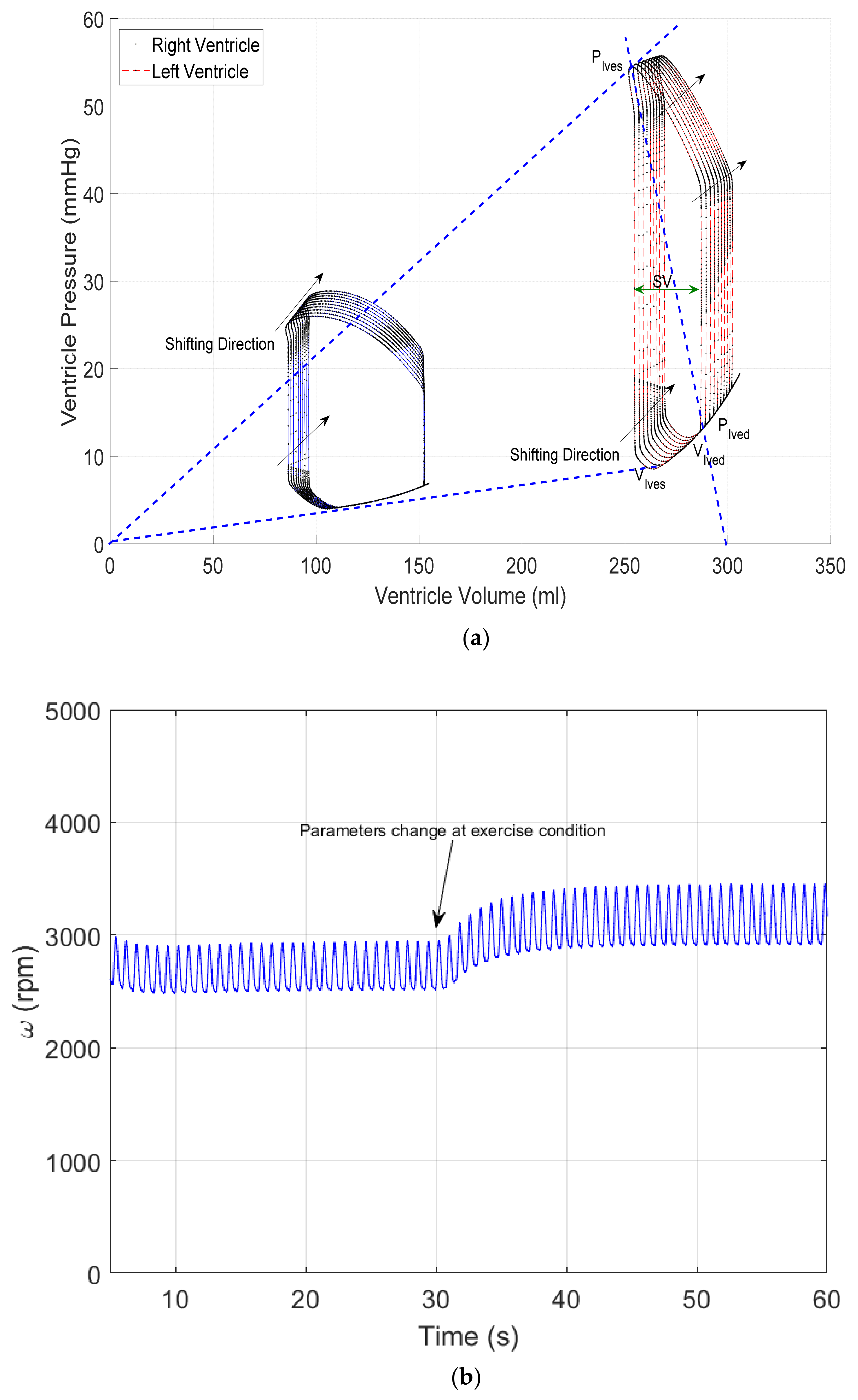
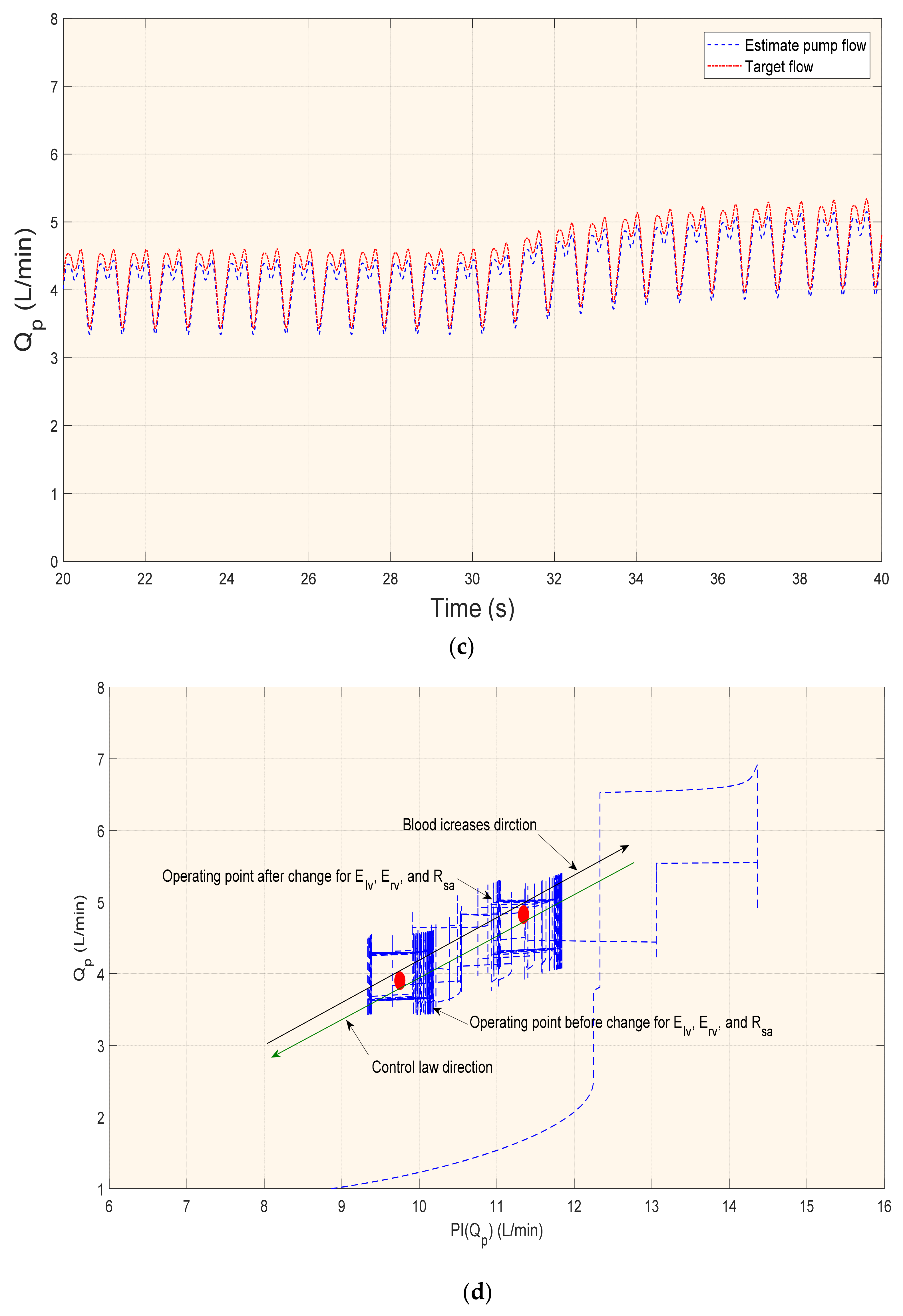
3.2. Exercise Scenario

Figure 5 shows the results of the hemodynamic parameters in the exercise condition. A severe condition of HF was simulated by inducing the system parameters at 30 s to evaluate the shift of the operating point outside the green zone. As a result, the controller shifted the SW to the right and produced larger Vlved and Vrved, as shown in Figure 5a. Consequently, both the peak-systolic LV pressure and SW were decreased. Therefore, the controller quickly responded to increase the ω from 2850 rpm to 3450 rpm, as shown in Figure 5b, and then changed Qp from 4.5 L/min to 5.2 L/min, as shown in Figure 5c.
In the exercise scenario, the sudden rise in the LVAD flow resulted in changes to the flow pulsation by the movement of the operating point up and to the right, along with the target preload flow line. When the average pump flow rises above the upper limit of 5 L/min, the control unit switches to a new control line with a lower slope (k = 0.5) in order to decrease the average pump flow. After this drop in the flow, the operation point immediately settles to the new line, as shown in Figure 5d. Table 2 shows the hemodynamic variables during the test conditions of HF associated with an LVAD.

4. Discussion

In a healthy human, the system of Frank–Starling regulates the heart’s pumping, where the volume of the LV is adjusted to reflect the changes in preload (that refers to the end-diastolic heart muscle fiber sarcomere length). This means that the LV ejects whatever the blood volume received. Instead, VADs are relatively insensitive to the preload, and hence the amount of blood supplied cannot be determined or sensed automatically [31]. Therefore, a pump control technique should maintain the flow within a secure operating zone. However, several conditions can harm the patient and sometimes lead to death. For example, over-pumping or a decrease in the preload, or reverse pumping flow and pulmonary edema caused by under pumping and the resulting reduction in the applied pressure of the differential pump, are the most adverse conditions that can be harmful to the patient and can be easily identified and prevented [8].
Different researchers claim that the preload parameter (left ventricle end-diastolic pressure) is an accurate parameter to detect or measure in order to physiologically adapt the cardiac perfusion [10,32]. Therefore, this work aimed to calculate the preload by implementing the Starling-like controller approach. In addition, the study investigated metabolic demand management techniques and, thus, cardiac preload adaptation. Therefore, the design method was to keep the Starling-like controller’s operating points within a safe and acceptable range. Figure 4 and Figure 5 illustrate that the mode of the adaptive operation point is achieved. The PI controller successfully changes the gradient angle of the preload line based on physiological demand. Table 2 depicts how all the hemodynamic variables varied within an acceptable domain during test conditions. One of the many challenges of establishing a suitable solution includes a broad range of HF physiological properties; poor ventricular function without essential residual cardiac function boosts ventricular function where sufficient aortic valve flow is possible [33,34]. Most VADs available on the market, both second and third generations, operate at a set target of operating points determined by a per-patient specialist clinician. Unless VADs are to be generally accepted as a care choice for HF patients, the quality of life of implant recipients must be maximized, and a pump management technique is thought to be essential to achieve this [35,36].
As reported in [27], a common constraint of the previously proposed control strategies is that most medical practitioners have not been able to understand the underlying philosophy. Thus, they easily return to the non-physiological speed manual control whenever inappropriate patient responses occur. However, decoupling an LVAD from the cardiovascular system under a manual pump speed control may cause adverse effects to patients, such as abdominal absorption or inadequate cardiovascular output, especially when there are variations in the cardiovascular state. This study developed and implemented a physiological controller based on sensorless and non-invasive approaches to indicate CVS preload and metabolic demand changes. This approach was designed to emulate the clinically obvious FSM to medical practitioners. The pump flow was non-invasively estimated using the PWM parameter and thus used to calculate target flow.
In recent work, Fetanat et al. [37] developed an adaptive physiological control algorithm for an IRBP to accommodate interpatient and intrapatient variations. The algorithm was implemented and tested to automatically adjust the heart pump to prevent suction and pulmonary congestion based on detecting Plved. The method used a pressure sensor to detect Plved in real-time mode. A different study was developed with a physiological controller using the features of pump inlet pressure. The perfusion of pump flow was adopted using the multi-objective controller to prevent LV suction, overload, and pump backflow. This method was successfully evaluated, in vitro, under different physiological conditions [38]. However, the implantation of additional sensors is not desirable, resulting in thrombus formation, reducing the system’s reliability, increasing cost, and requiring regular calibration due to measurement deviations.
This study has certain limitations to its conclusions because the software model omitted reflex control and auto-regulatory systems. There may be a significant impact on the current control strategy from the reflex and autoregulatory systems’ ability to adjust to short-term changes in the cardiovascular system automatically. The baroreceptor response was also found to be relevant in HF and exercise conditions, suggesting that further modification of the model to add the reflex control system is needed to evaluate the controller [39]. The proposed control algorithms also need to be considered for evaluation in animal experiments and clinical trials in the future.

5. Conclusions

In this study, an optimal H-infinity controller was used for designing a physiological controller, and subsequently implemented to drive an LVAD for HF patients. The control method was developed and evaluated using MATLAB software. This software consisted of three models: pump flow estimator, an LVAD, and CVS. The design method was implemented to emulate FSM by changing the safe range (green zone) operating points under different physiological conditions. The boundaries of the green zone were limited by the maximum and minimum of the pump flow. The PI controller was also used to change the angle of the preload control lines within the green zone to achieve optimum physiological perfusion.
The experimental procedure was designed to evaluate the implemented system in two scenarios ranging from rest to exercise of the HF patient. In both scenarios, the hemodynamic parameters of CVS were induced at 30 s to evaluate the quick response of the controller to change the operating points within the preload control lines. The simulation results demonstrated that the proposed controller was robust to change the system parameters of CVS within an acceptable clinical domain to prevent suction and over perfusion.

Author Contributions

Conceptualization, M.B.; methodology, M.B. and A.-H.A.; software, M.B., A.A. and K.A.; validation, M.B., A.A. and A.-H.A.; formal analysis, M.B., S.A., A.G., H.F.I. and A.-H.A.; visualization, all authors were involved; writing—original draft preparation, all authors were involved in the manuscript writing. All authors have read and agreed to the published version of the manuscript.

Funding

This research was funded by the deputyship for Research and Innovation, Ministry of Education, Saudi Arabia, grant number IFP-2020-31.

Institutional Review Board Statement

Not applicable.

Informed Consent Statement

Not applicable.

Data Availability Statement

Not applicable.

Acknowledgments

The authors extend their appreciation to the deputyship for Research and Innovation, Ministry of Education in Saudi Arabia for funding this research work through the project number IFP-2020-31.

Conflicts of Interest

The authors declare no conflict of interest.

Appendix A

The following table is shown as the nomenclature for the CVS, estimator model, and for the designed controller.
Table A1. Nomenclature of the CVS, estimator, and controller.
SymbolDescription
cardiovascular System Model
R i n inlet cannula resistance
R o u t outlet cannula resistance
L i n inlet cannula inductance
L o u t outlet cannula inductance
P t h o r 1   and   P t h o r 2 intrathoracic pressures
R s u c suction resistance
V k blood vessel compartment
Q k blood flow across the valves
P i pressure in heart chamber
Estimator Model
P W M pulse-width modulation
P I ω pulsatility index of pump rotational speed
Q p pulsatile flow
ξ ( n ) states of model estimator
u ( n ) pump control input
μ ( n ) system noise
Controller
P I Q P pulsatility of pump flow
θ gradient angle
Τ η δ lower linear fractional transformation
ψ   and   Ω positive semi-definite solutions to the Riccati equations
K c controller gain
K e estimator gain
λ positive scalar
K ( s ) controller matrix
P ( s ) plant (LVAD)

References

  1. Cowie, M.R. The heart failure epidemic: A UK perspective. Echo Res. Pract. 2017, 4, 15–20. [Google Scholar] [CrossRef] [PubMed] [Green Version]
  2. Cowie, M.R. Incidence and aetiology of heart failure; a population-based study. Eur. Heart J. 1999, 20, 421–428. [Google Scholar] [CrossRef] [PubMed]
  3. Fox, K.; Cowie, M.; Wood, D.; Coats, A.; Gibbs, J.; Underwood, S.; Turner, R.; Poole-Wilson, P.; Davies, S.; Sutton, G. Coronary artery disease as the cause of incident heart failure in the population. Eur. Heart J. 2001, 22, 228–236. [Google Scholar] [CrossRef] [PubMed]
  4. Chatterjee, A.; Schmitto, J.D. The evolution of mechanical circulatory support (MCS): A new wave of developments in MCS and heart failure treatment. J. Thorac. Dis. 2018, 10 (Suppl. S15), S1688. [Google Scholar] [CrossRef]
  5. Frazier, O.H. Mechanical cardiac assistance: Historical perspectives. Semin. Thorac. Cardiovasc. Surg. 2000, 12, 207–219. [Google Scholar] [CrossRef]
  6. Mehra, M.R.; Uriel, N.; Naka, Y.; Cleveland, J.C., Jr.; Yuzefpolskaya, M.; Salerno, C.T.; Walsh, M.N.; Milano, C.A.; Patel, C.B.; Hutchins, S.W.; et al. A fully magnetically levitated left ventricular assist device. N. Engl. J. Med. 2019, 380, 1618–1627. [Google Scholar] [CrossRef]
  7. Pac, M.; Kocabeyoglu, S.S.; Kervan, U.; Sert, D.E.; Koca, S.; Ece, I.; Pac, F.A. Third generation ventricular assist device: Mid-term outcomes of the HeartWare HVAD in pediatric patients. Artif. Organs 2018, 42, 141–147. [Google Scholar] [CrossRef]
  8. Bozkurt, S. Physiologic outcome of varying speed rotary blood pump support algorithms: A review study. Australas. Phys. Eng. Sci. Med. 2016, 39, 13–28. [Google Scholar] [CrossRef]
  9. Stevens, M.C.; Stephens, A.; AlOmari, A.H.H.; Moscato, F. Physiological control. In Mechanical Circulatory and Respiratory Support; Elsevier Inc.: Amsterdam, The Netherlands, 2018; pp. 627–657. [Google Scholar]
  10. AlOmari, A.H.; Savkin, A.V.; Stevens, M.; Mason, D.G.; Timms, D.L.; Salamonsen, R.F.; Lovell, N.H. Developments in control systems for rotary left ventricular assist devices for heart failure patients: A review. Physiol. Meas. 2012, 34, 1. [Google Scholar] [CrossRef]
  11. Fetanat, M.; Stevens, M.; Hayward, C.; Lovell, N.H. A Sensorless Control System for an Implantable Heart Pump using a Real-time Deep Convolutional Neural Network. IEEE Trans. Biomed. Eng. 2021, 68, 3029–3038. [Google Scholar] [CrossRef]
  12. Bakouri, M.A.; Salamonsen, R.F.; Savkin, A.V.; AlOmari, A.H.; Lim, E.; Lovell, N.H. A Sliding Mode-Based Starling-Like Controller for Implantable Rotary Blood Pumps. Artif. Organs 2014, 38, 587–593. [Google Scholar] [CrossRef]
  13. Huang, F.; Ruan, X.; Fu, X. Pulse-pressure–enhancing controller for better physiologic perfusion of rotary blood pumps based on speed modulation. ASAIO J. 2014, 60, 269–279. [Google Scholar] [CrossRef]
  14. Wu, Y.; Allaire, P.E.; Tao, G.; Olsen, D. Modeling, estimation, and control of human circulatory system with a left ventricular assist device. IEEE Trans. Control Syst. Technol. 2007, 15, 754–767. [Google Scholar] [CrossRef]
  15. Arndt, A.; Nüsser, P.; Graichen, K.; Müller, J.; Lampe, B. Physiological control of a rotary blood pump with selectable therapeutic options: Control of pulsatility gradient. Artif. Organs 2008, 32, 761–771. [Google Scholar] [CrossRef]
  16. Chang, Y.; Gao, B.; Gu, K. A model-free adaptive control to a blood pump based on heart rate. Asaio J. 2011, 57, 262–267. [Google Scholar] [CrossRef]
  17. Son, J.; Du, D.; Du, Y. Feedback Control of Rotary Blood Pump for Preventing Left Ventricular Suction. In Proceedings of the 2019 American Control Conference (ACC), Philadelphia, PA, USA, 10–12 July 2019; pp. 5426–5431. [Google Scholar]
  18. Petukhov, D.; Korn, L.; Walter, M.; Telyshev, D. A novel control method for rotary blood pumps as left ventricular assist device utilizing aortic valve state detection. BioMed Res. Int. 2019, 2019, 1732160. [Google Scholar] [CrossRef] [Green Version]
  19. Telyshev, D.V. A Mathematical Model for Estimating Physiological Parameters of Blood Flow through Rotary Blood Pumps. Biomed. Eng. 2020, 54, 163–168. [Google Scholar] [CrossRef]
  20. Wang, Y.; Peng, J.; Rodefeld, M.D.; Luan, Y.; Giridharan, G.A. A sensorless physiologic control strategy for continuous flow cavopulmonary circulatory support devices. Biomed. Signal Process. Control 2020, 62, 102130. [Google Scholar] [CrossRef]
  21. Ayre, P.J.; Vidakovic, S.S.; Tansley, G.D.; Watterson, P.A.; Lovell, N.H. Sensorless flow and head estimation in the VentrAssist rotary blood pump. Artif. Organs 2020, 24, 585–588. [Google Scholar] [CrossRef]
  22. Wang, Y.; Koenig, S.C.; Slaughter, M.S.; Giridharan, G.A. Rotary blood pump control strategy for preventing left ventricular suction. ASAIO J. 2015, 61, 21–30. [Google Scholar] [CrossRef] [PubMed]
  23. Ishii, K.; Saito, I.; Isoyama, T.; Nakagawa, H.; Emiko, N.; Ono, T.; Shi, W.; Inoue, Y.; Abe, Y. Development of Normal-Suction Boundary Control Method Based on Inflow Cannula Pressure Waveform for the Undulation Pump Ventricular Assist Device. Artif. Organs 2012, 36, 812–816. [Google Scholar] [CrossRef] [PubMed]
  24. Reesink, K.; Dekker, A.; Van der Nagel, T.; Beghi, C.; Leonardi, F.; Botti, P.; De Cicco, G.; Lorusso, R.; Van der Veen, F.; Maessen, J. Suction due to left ventricular assist: Implications for device control and management. Artif. Organs 2007, 31, 542–549. [Google Scholar] [CrossRef] [PubMed]
  25. Liang, L.; Meki, M.; Wang, W.; Sethu, P.; El-Baz, A.; Giridharan, G.A.; Wang, Y. A suction index based control system for rotary blood pumps. Biomed. Signal Process. Control 2020, 62, 102057. [Google Scholar] [CrossRef]
  26. Salamonsen, R.; Mason, D.; Ayre, P. Response of Rotary Blood Pumps to Changes in Preload and Afterload at a Fixed Speed Setting Are Unphysiological When Compared with the Natural Heart. Artif. Organs 2011, 35, E47–E53. [Google Scholar] [CrossRef]
  27. Salamonsen, R.F.; Lim, E.; Gaddum, E.; Alomari, A.H.; Gregory, S.D.; Stevens, M.; Mason, D.G.; Fraser, J.F.; Timms, D.; Karunanithi, M.K.; et al. Theoretical foundations of a Starling-like controller for rotary blood pumps. Artif. Organs 2012, 36, 787–796. [Google Scholar] [CrossRef]
  28. Bakouri, M.A.; Savkin, A.V.; Alomari, A.H. Nonlinear modelling and control of left ventricular assist device. Electron. Lett. 2015, 51, 613–615. [Google Scholar] [CrossRef]
  29. Xu, S.Y.; Chen, T.W. Robust H-infinity control for uncertain stochastic systems with state delay. IEEE Trans. Autom. Control 2002, 47, 2089–2094. [Google Scholar]
  30. Lim, E.; Dokos, S.; Salamonsen, R.; Rosenfeldt, F.; Ayre, P.; Lovell, N. Numerical Optimization Studies of Cardiovascular-Rotary Blood Pump Interaction. Artif. Organs 2012, 36, E110–E124. [Google Scholar] [CrossRef]
  31. Giridharan, G.; Skliar, M. Control Strategy for Maintaining Physiological Perfusion with Rotary Blood Pumps. Artif. Organs 2003, 27, 639–648. [Google Scholar] [CrossRef]
  32. Arndt, A.; Nüsser, P.; Lampe, B. Fully autonomous preload-sensitive control of implantable rotary blood pumps. Artif. Organs 2010, 34, 726–735. [Google Scholar] [CrossRef]
  33. Wu, Y. Adaptive physiological speed/flow control of rotary blood pumps in permanent implantation using intrinsic pump parameters. Asaio J. 2009, 55, 335–339. [Google Scholar] [CrossRef]
  34. Pauls, J.P.; Stevens, M.C.; Bartnikowski, N.; Fraser, J.F.; Gregory, S.D.; Tansley, G. Evaluation of physiological control systems for rotary left ventricular assist devices: An in-vitro study. Ann. Biomed. Eng. 2016, 44, 2377–2387. [Google Scholar] [CrossRef]
  35. Shekar, K.; Gregory, S.D.; Fraser, J.F. Mechanical circulatory support in the new era: An overview. Crit. Care 2016, 20, 66. [Google Scholar] [CrossRef] [Green Version]
  36. Wang, Y.; Koenig, S.C.; Wu, Z.; Slaughter, M.S.; Giridharan, G.A. Sensor-based physiologic control strategy for biventricular support with rotary blood pumps. Asaio J. 2018, 64, 338–350. [Google Scholar] [CrossRef]
  37. Fetanat, M.; Stevens, M.; Hayward, C.; Lovell, N.H. A physiological control system for an implantable heart pump that accommodates for interpatient and intrapatient variations. IEEE Trans. Biomed. Eng. 2019, 67, 1167–1175. [Google Scholar] [CrossRef] [Green Version]
  38. Petrou, A.; Monn, M.; Meboldt, M.; Schmid Daners, M. A novel multi-objective physiological control system for rotary left ventricular assist devices. Ann. Biomed. Eng. 2017, 45, 2899–2910. [Google Scholar] [CrossRef]
  39. Creager, M.A. Baroreceptor reflex function in congestive heart failure. Am. J. Cardiol. 1992, 69, 10–16. [Google Scholar] [CrossRef]
Figure 1. Physiological control method. (a) Cardiac function curves at different contractility conditions. (b) Preload control mechanism; A, B, C, D: operating points; L 1 , L 2 , L n , L n 1 : preload control lines; C 1 , C 2 : flow preload curve; θ 1 ,   θ 2 : angles.
Mathematics 10 00731 g001
Figure 2. Physiological control method.
Mathematics 10 00731 g002
Figure 3. Electrical equivalent circuit analogue of CVS–LVAD interaction. R i n : inlet cannula resistances; R o u t : outlet cannula resistances; L i n : inlet cannula inertances; L o u t : outlet cannula inertances; R s u c : suction resistance; and P t h o r 1 and P t h o r 2 : intrathoracic pressures.
Mathematics 10 00731 g003
Figure 4. Hemodynamic variable results in the rest condition; (a) pressure–volume loops; (b) pump speed; (c) estimated flow vs. target pump flow; (d) pump flow pulsatility vs. estimated flow.
Mathematics 10 00731 g004aMathematics 10 00731 g004bMathematics 10 00731 g004c
Figure 5. Hemodynamic variable results in the exercise condition; (a) pressure–volume loops; (b) pump speed; (c) estimated flow vs. target pump flow; (d) pump flow pulsatility vs. estimated flow.
Mathematics 10 00731 g005aMathematics 10 00731 g005b
Table 1. CVS model parameters used to simulate heart failure conditions.
VariableUnitHealthyHeart Failure (HF)
V t o t a l mL53005800
E e s , r v mm Hg/mL1.72350.5322
E e s , l v mm Hg/mL3.54430.7100
R s a mm Hg*s/mL0.74111.1100
Table 2. Hemodynamic data of the model for both healthy and heart failure patients.
VariableUnitHF + LVAD
NormalRestExercise
Target flow (Qt)L/min4.953.655.52
Pump flow (Q)L/min4.53.405.05
Left ventricle end-diastolic volume (Vlved)mL120140.00285.3
Left ventricle end-diastolic pressure (Plved)mmHg9.508.5012.79
Left ventricle end-systolic volume (Vlves)mL65.5050.00252.4
Left ventricle end-systolic pressure (Plves)mmHg120116.553.50
Stroke volume (SV)mL102.0090.0035.00
Publisher’s Note: MDPI stays neutral with regard to jurisdictional claims in published maps and institutional affiliations.

