1. Introduction
Quantum dot lasers have superior features compared to quantum well counterparts [
1,
2,
3,
4] such as temperature independence, a low threshold current [
5], they can be operated with low chirp for both ground state (Grs) and excited state (Exs) lasing [
4], and have better resistance values for optical feedback [
6]. The feature of being relatively insensitive to temperature makes quantum dot (Q-Dot) lasers avoid the need for thermoelectric coolers [
7]. Since these mentioned features mean that Q-Dot lasers are compact, cheap, lightweight, and low power systems, they are appropriate candidates for applications in optical communications [
7].
Low-cost directly adjustable lasers will play an important role in next-generation telecommunication links for developing uncooled and non-insulating communication devices. As a result, Q-Dot lasers are very promising for such applications. In optical communication systems, a 1.55 µm light source is required because of the low loss in transmission. InGaAs-GaAs Q-Dot devices do not allow laser emissions over 1.45 µm, which causes information loss in long-distance transmissions. For this reason, to achieve standard long-distance transmission, one uses long-haul optical transmission at a wavelength of up to 1.55 µm. Consequently, one chooses the InAs-InP(113)B Q-Dot lasers with the InAs Q-Dot laser grown on an InP substrate that emits at a wavelength of 1.55 µm [
3,
8,
9]. Owing to their simple fabrication methods and low manufacturing costs, the gain-switched semiconductor laser diodes are preferred over their counterparts. Therefore, in this study, we used the gain-switching method to obtain short pulses. To date, although several studies have been performed to investigate 1.55 µm InAs-InP Q-Dot lasers, to the best of our knowledge, no detailed work has been performed under the gain-switching condition for InAs-InP Q-Dot lasers based on multi-population rate equations involving nonlinear gain. For this, an external optical Gaussian beam (EOGB) was applied to the excited state (Exs) of the Q-Dot laser with current injection to the wetting layer (Wly) to investigate the properties of the gain-switched pulses. Although, Q-Dot lasers have superior performance, they cannot always satisfy the expected features in reality due to the homogeneous and inhomogeneous broadenings and the gain compression factor [
10,
11,
12]. To obtain an appropriate and suitable approach to experimental results theoretically, as many aspects of real experiments as possible should be taken into account when performing the simulation. For this, the effect of the homogeneous and the inhomogeneous broadening with the effect of the gain compression were taken into consideration in this study. Therefore, this paper is organized as follows:
Section 2 introduces the theoretical description of multi-population rate equations for the direct relaxation model considering the nonlinear-gain case. The obtained results discussed in
Section 3 show that by applying an EOGB into the Exs, very short pulses, with a pulse width of around 26 ps and high peak power, are generated due to the Exs emissions at low currents. In addition, it was shown that the contribution of excited state to gain-switched output pulses does not depend on only the value of the inhomogeneous broadening but also on the magnitude of the applied current. Furthermore, the effect of homogeneous and inhomogeneous broadening on the differential gain, the gain compression factor, and the threshold current is also investigated. Finally, our results are summarized and concluded in
Section 4.
2. Materials and Methods
The laser model used in this study for InAs-InP(113)B Q-Dot is based on the multi population rate equations for the direct relaxation model described in [
2,
11,
13]. The laser carrier and photon density equations were solved by the fourth order Runge–Kutta method using MATLAB software to investigate the carrier dynamics in the two lowest energy levels, Grs and Exs. The initial values of carrier and photon densities were taken to be a zero. A stimulated emission term was also added to the Exs to allow lasing from both states. The effect of temperature and carrier loss were neglected in the study. We assumed that the carriers were directly injected from the contacts to the Wly; therefore, the carrier dynamics were not considered in the barrier. Direct transition from the Wly to the Grs was introduced to reproduce the experimental results [
2,
11,
13]. The Q-Dot active region consists of the Q-Dots ensemble having different sizes. In the model, in order to consider the effect of the inhomogeneous broadening (Γ
ihom), the Q-Dot ensemble is divided into 2X + 1 groups, depending on their resonant energies for the interband transition [
14,
15].
Figure 1 shows the relaxation mechanisms in the xth Q-Dot subgroup. Energies of Exs and Grs of xth Q-Dot are represented as
and
, respectively. As a result, the longitudinal cavity photon modes of up to 2P + 1 are constructed in the cavity [
13]. When the index x is equal to X, this situation corresponds to the central Q-Dot group. When index p is equal to P, this case corresponds to the central mode with the transitional energies of
and
for Exs and Grs, respectively. Each Q-Dot group energy width (
) and mode energy separation (
) are assumed to be equal and taken to be as 1 meV [
13]. The xth Q-Dot group energy and pth mode energies are indicated by:
When injection current I is applied to the Wly of the Q-Dot laser, some carriers move to the lower state and with a capture time of for the transition from the Wly to and a relaxation time of for the Wly to the transition. Some photons are emitted from the Wly due to spontaneous emission over a time . However, in the Exs, some carriers are relaxed into the with a relaxation time . Furthermore, the more energetic carriers are thermally transferred to the Wly with a time . The other carriers recombine spontaneously with an emission time or by the stimulated emission of photons. The same mechanism for the carrier dynamics transitions is applied at the Grs level. The same processes occur for the carrier population in the Grs level with regard to the Exs.
The capture and relaxation times can be calculated [
13] as:
Here
is the carrier density in the Wly,
,
are the phonon and Auger coefficients in the Wly and Exs, respectively. Their values are estimated experimentally [
16].
is the occupation probabilities in xth group of Q-Dot in the Exs and Grs.
is the degeneracy of the Exs and Grs,
is the Q-Dot density and
is the carrier density in the Exs and Grs of xth Q-Dot.
is the density rate of xth Q-Dot in the Exs and Grs.
To calculate
, the Q-Dot size distribution is assumed to be a Gaussian function given as:
The full-width half-maximum of the Gaussian function is given as Γ
inh = 2.35 σ. In other words, Γ
inh is described as inhomogeneous broadening. The carrier escape time is related to the carrier capture time [
17] and given as:
where
is the degeneracy of the Wly, k
B is the Boltzmann constant, T is the temperature, and E
Wly is the energy of the Wly.
Change in the carrier density in the Wly, Exs, and Grs and change in the photon density in the Exs and Grs for the multi-modes rate equations are given as:
V is the volume,
q is the charge,
Γ is the confinement factor, and
vg is the group velocity.
, and
indicate the average capture times from the Wly to Exs and from the Wly to Grs in Q-Dot ensemble. They are defined as follows:
Nonlinear gain in Exs and Grs is given as:
c,
εo,
ħ,
nr, and
mo are the speed of light, dielectric constant in free space, Planck constant, refractive index of active medium, and free mass of electron, respectively.
, is the transition matrix element [
10] and it is estimated approximately at 2m
oEExs0,Grs0 for InAs [
17].
is the photon density of the
pth mode emitted from Exs and Grs. The homogeneous broadening of the stimulated emission process is assumed to be Lorentzian such that
,
is the full-width half-maximum of homogeneous broadening.
The gain saturation parameter,
of the Exs and Grs, is given as:
where
is the photon lifetime and it is computed from the following equations:
where R1 and R2 are the reflectivities of the mirrors and
L is the length of the laser.
is the internal loss, while the mirror loss is calculated using to the equation:
.
in Equation (20) is the Lorentzian function and given as:
The photon density in Exs and Grs is expressed as:
where
is the spontaneous coupling factor.
opt in Equation (13) is the photon density due to the applied EOGB to Exs in a round-trip time τ
RT = 2 L/v
g. This term is equal to the number of photons per second per volume irradiating the Exs level in a single round-trip.
Pi indicates the applied peak power of the Gaussian pulse to Exs.
The parameters used in the simulations are given in
Table 1. The values of these parameters were obtained from [
13,
18,
19,
20].
In the algorithm, firstly the constant values and parameters of the laser are determined from
Table 1. After that, since the process repeats for every Q-Dot and every mode, the number of modes (i.e.,
p) and number of Q-Dots (i.e.,
x) are defined. As a result, the created simulation consists of three intertwined loops. Before starting all loops, the current is applied to the Wly of the laser. The outermost loop returns as many as the number of quantum dots we have determined (here, our results are relevant to three Q-Dots). In this loop, the energy differences are found with Equation (1). Inside the quantum dot loop, there is a second loop that is repeated according to the mode number. Within the mode loop, the energy differences between the modes are calculated by Equation (2). After these steps are completed, the homogeneous and inhomogeneous broadenings are calculated using Equations (8) and (19). By using the calculated homogeneous and inhomogeneous broadenings and the equations that are numbered as Equations (17), (18) and (20), the material gain and gain compression factor of Exs and Grs are calculated. After that, the third loop that provides the calculation of carrier and photon densities of Exs and Grs is started. In this loop, the rate equations defined as Equations (12)–(14), (23) and (24) are solved using fourth order Runge–Kutta Method. When this loop is completed, the photon and carrier density values of the relevant mode of the related quantum dot is reached. Then, the loops repeated by the number of modes and repeated by the number of quantum dots are finished, respectively. In our study, three Q-Dots and three modes were examined and, according to this algorithm, there are three modes for each Q-Dot. Since there are three Q-Dots, the center Q-Dot corresponds to the second Q-Dot. Similar to other Q-Dots, there are three modes for the second Q-Dot. Additionally, the results are written using the modes of the center Q-Dot (it is the second Q-Dot for our simulation). The sum of the modes can be calculated by summing the three modes taken from the second Q-Dot.
3. Discussion and Results
A 1.55 μm InAs-InP (113)B Q-Dot laser was used in the simulation. The following equation was used to calculate the applied AC current
I, with frequency
, and amplitude
Irf [
21,
22].:
Unlike previous studies, here, the nonlinear gain was included in multi-population rate equations.
X and P are taken as X = P = 1 (i.e., it was assumed that there are three Q-Dot ensembles) and an Γhom of 15 meV and Γihom of 45 meV has been used in the following results unless stated otherwise. For these values the gain compression factor, is calculated as 7.8 × 10⁻¹⁶ cm3 for Exs and Grs. To observe the radiation simultaneously from both Exs and Grs, the Irf was taken to be 40 mA in the simulations.
Since Γ
hom and Γ
ihom affect the threshold current (
Ith), the differential gain and the gain compression factor [
10,
12], first without EOGB, and the effect of Γ
hom and Γ
ihom on these mentioned parameters were investigated. Subsequently, an EOGB was applied to the Exs to observe how the optical beam illumination affects the gain-switching output pulses.
The
Ith was calculated as 30 mA for Exs and 2 mA for Grs for the linear-gain case (
= 0) (see
Figure 2a); 21 mA for Exs and 2 mA for Grs for the nonlinear-gain case (
≠ 0) were obtained (see
Figure 2b). The total threshold current (Grs + Exs) for both cases was calculated as 2 mA. As seen in
Figure 2b, deviation from
Figure 2a due to
is because of the direct relaxation from the Wly to Grs.
Γ
ihom changes between 30 and 80 meV at room temperature [
23,
24], therefore, we changed it from 30 meV to 80 meV. In this case, Γ
hom is taken as to be 15 meV at room temperature [
11]. Similarly, since the range of Γ
hom is between 10 and 30 meV [
2], Γ
hom is changed from 10 to 30 meV and Γ
ihom is taken to be 45 meV.
For the center subgroup of the Q-Dot (second subgroup), when Γ
ihom is changed from 30 meV to 80 meV, as the I
th of Exs drops from 27 mA to 10 mA the I
th of Grs increases from 1 mA to 6 mA (see
Figure 3). If Γ
ihom is greater than 70 meV, the threshold current increases as the photon density of Grs decreases and finally the threshold currents of Grs and Exs become the same at 11 mA. The effect of Γ
ihom on the differential gain is shown in
Figure 4. As seen in the figure, as Γ
ihom increases, the differential gain of Exs and Grs decreases. Similar results were also observed in [
12].
The behavior of Γ
hom on
Ith and on differential gain is similar to that of Γ
ihom, providing similar differential gain characteristics as in
Figure 4 when Γ
hom is increased from 10 meV to 30 meV. For the center subgroup of the Q-Dot, as Γ
hom is increased from 10 meV to 30 meV,
Ith of Exs decreases up to 22.5 meV (dropping from 26 mA to 10 mA) and after that point it slightly increases.
Ith of Grs increases from 1 mA to 6 mA (see
Figure 5). When Γ
hom is greater than 22.5 meV the photon density of Grs decreases, whereas the threshold current increases, yielding a threshold current of 14 mA, which is equal to that of the Exs.
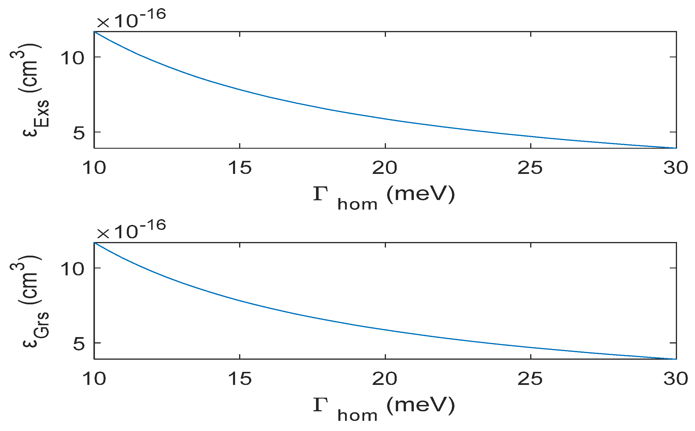
Figure 6 indicates the effect of Γ
hom on the gain compression factors of Exs and Grs. As seen in the figure, the gain compression factor decreases with the increasing Γ
hom.
As seen in the results, the differential gain of Exs is greater than that of the Grs because degeneracy of the Exs is twice that of the Grs. However, the gain compression factor is the same for Grs and Exs. Our results also showed that the output power decreases with the increasing Γhom and Γihom.
As mentioned before, the threshold current was obtained at 2 mA for the Grs and 24 mA for the Exs for the nonlinear-gain case. Therefore, to observe the gain-switched output pulses and also the simultaneous emission from both the Grs and the Exs, we applied I
rf of 40 mA.
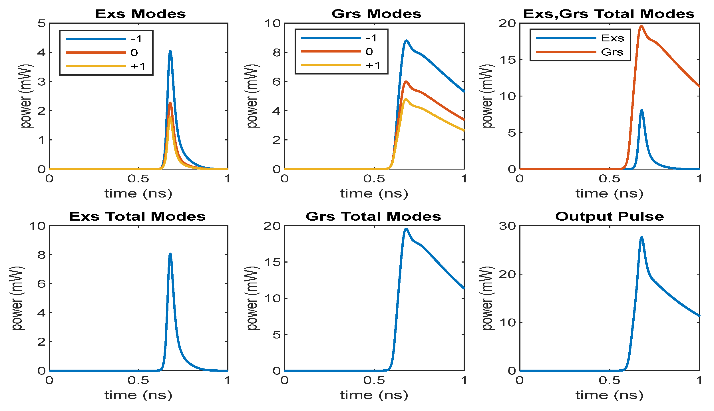
Figure 7 indicates the gain-switched output pulses for an I
rf of 40 mA. As shown in the figures, the Grs pulse width is longer (370 ps), while the Exs pulse width is narrow (43 ps). It can be also observed from the figure that the Exs and Grs together contribute to the output pulses since the applied current magnitude is greater than the threshold currents of both states. Therefore, the generated pulses are due to both Exs and Grs emission. The total (Exs + Grs) pulse width is 255 ps and the peak power is 28 mW. As seen in the results, the pulse width of the gain-switched output pulses are long. We also observed that increasing the injection current leads to both the peak power and pulse width increasing. The reason for the increase in the output pulse width with the current is that, although the photon density of the Grs increases with the current, the Grs photon density decreases slowly after reaching the maximum value, as seen in
Figure 7. However, the Exs photon density decreases rapidly compared to that of the Grs, yielding a shorter output pulse. It can be said that the long pulses in the InAs-InP (113)B lasers are emitted from the InP ground state.
For InGaAs-GaAs lasers, it was shown that [
22] Grs emission is completely saturated in the light-current characteristics, while the Exs emission increases with the increasing current. As a result, if the injection current is increased, the Exs radiation becomes dominant over that of Grs, yielding shorter pulses owing to Exs radiation. Investigation on the InAs-GaAs monolithic Q-Dot lasers revealed that, when the applied injection current increases, the width of the gain-switched pulse decreases [
25]. However, in the case of InAs-InP (113)B lasers, the Grs emission does not go to saturation completely (see
Figure 2) with the increasing injection current, instead both Grs and Exs emissions increase with the increasing current. Therefore, as mentioned before, the output pulse width of InAs-InP lasers increases with the increasing injection current as compared to that of InAs-GaAs lasers.
Furthermore, our results showed that as Γ
hom and Γ
ihom increase the
Ith of Exs decreases, whereas
Ith of Grs increases (see
Figure 3 and
Figure 5). Therefore, according to the magnitude of the applied current, even with a smaller value of Γ
ihom, the contribution of Exs to output pulses is possible. In order to show this, 25 mA of
Irf current is applied and the gain-switched output pulses were obtained for Γ
ihom = 30 meV (Γ
ihom < Δ
Edif = E
Exs0-E
Grs0 =48 meV) and Γ
ihom = 55 meV (Γ
ihom > Δ
Edif = 48 meV). As seen in
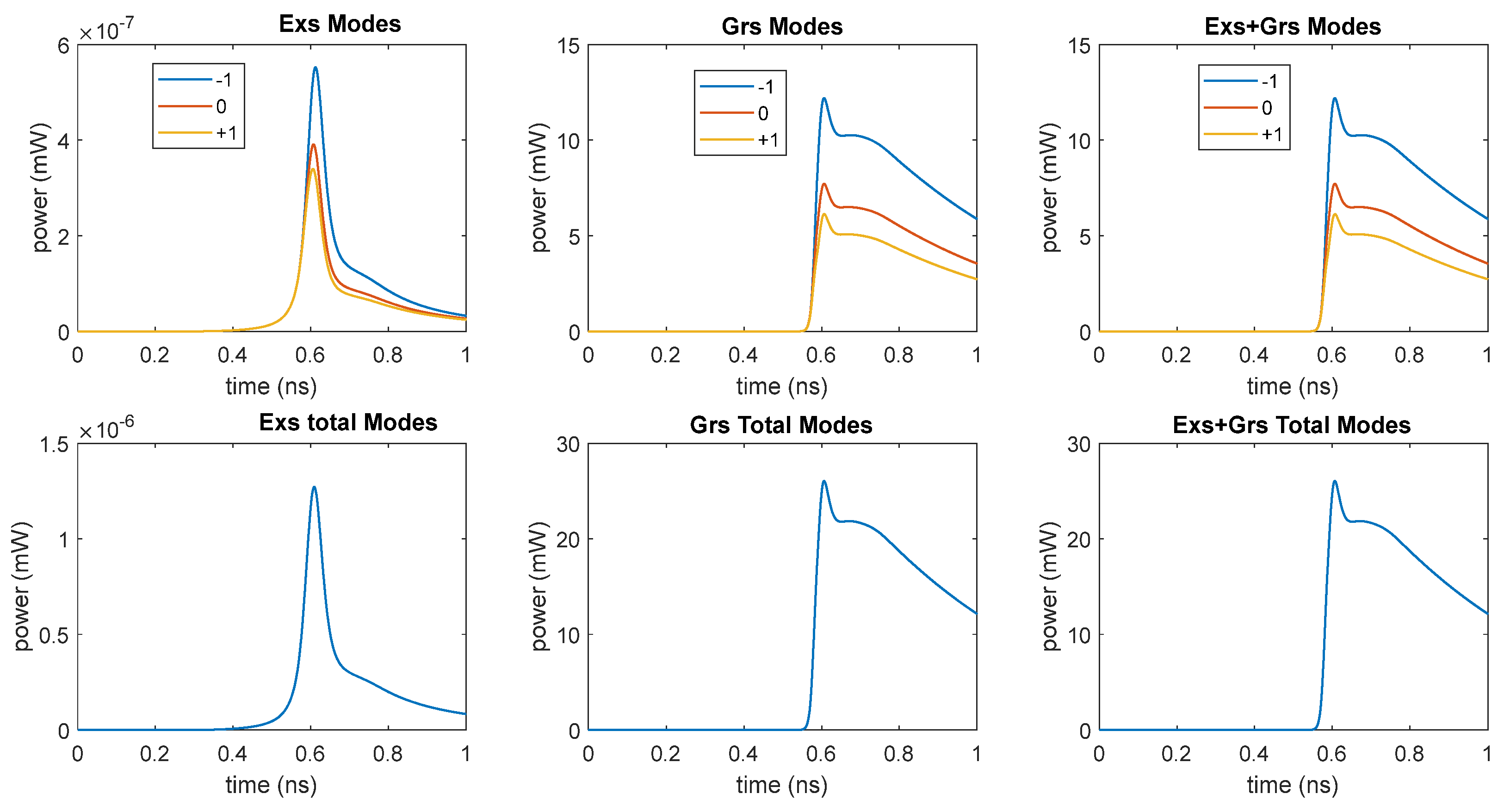
Figure 8 and
Figure 9, the output pulse with a full-width half-maximum (FWHM) of 386 ps and peak power of 26 mW for Γ
ihom = 30 meV is generated from Grs emission only. However, since
Ith of Exs decreased for Γ
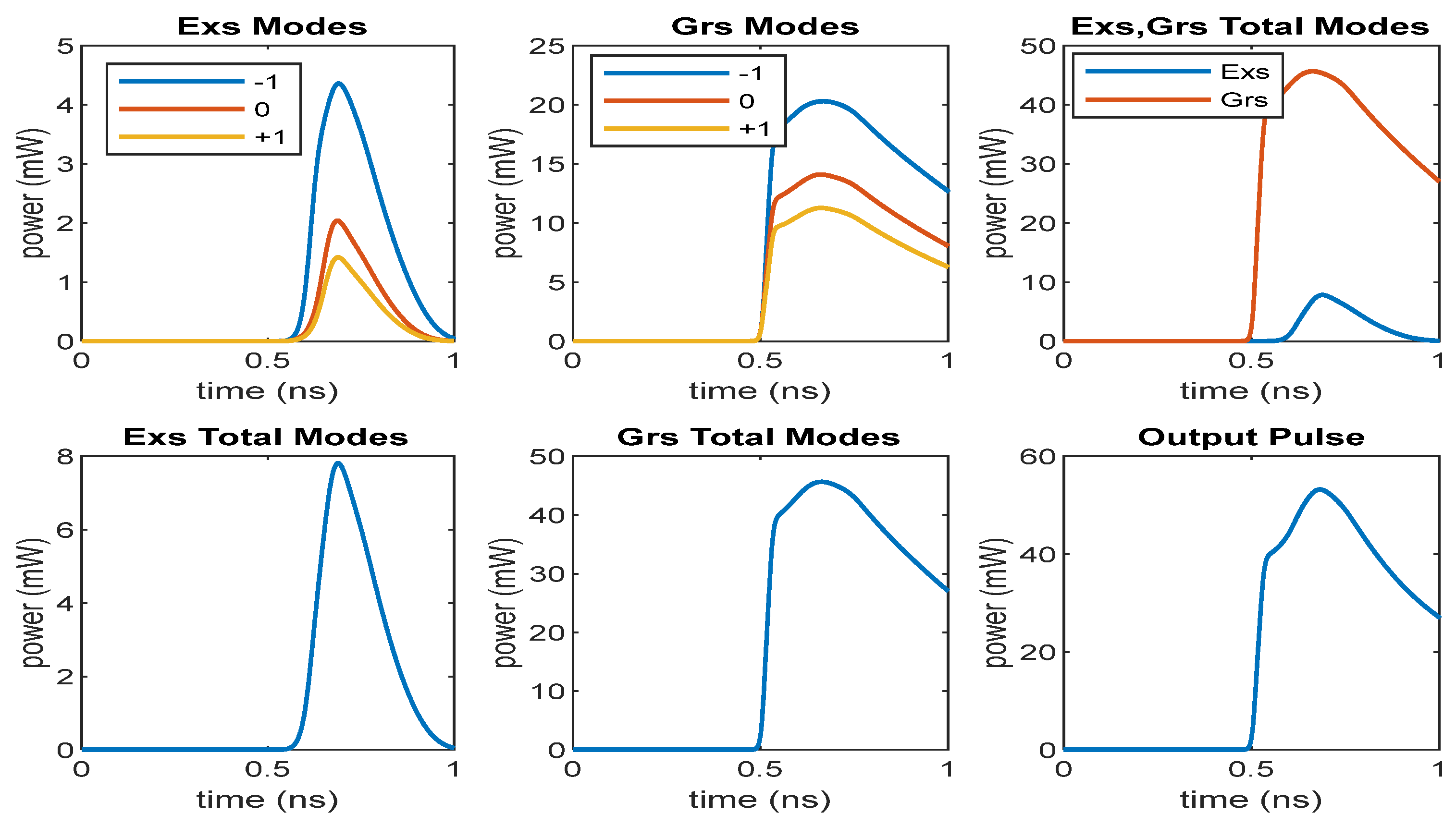
ihom = 55 meV, both Grs and Exs contribute the output pulse providing an FWHM of 233 ps and peak power of 10 mW. If we apply a current greater than the peak current of 25 mA, for example 60 mA for Γ
ihom = 30 meV, both Grs and Exs contribute to the lasing process simultaneously, as shown in
Figure 10 producing an FWHM of 478 ps and peak power of 53 mW. Briefly, we can say that the contribution of Exs to gain-switched output pulses depend on not only the value of Γ
ihom, which is smaller or greater than the energy difference between Exs and Grs, but also on the magnitude of the applied current. In addition, it can be also observed from the results that the width of pulses are long due to dominant effect of the Grs emission as mentioned before. Wang et al. [
12] showed that if Γ
ihom is smaller than the energy difference between Exs and Grs (Δ
Edif = E
Exs0-E
Grs0), lasing occurs only due to Grs if Γ
ihom is greater than the Δ
Edif; both Grs and Exs contribute to the lasing process. However, as seen from our results, Exs lasing depends on the magnitude of current as well as on the value of Γ
ihom.
According to obtained results, we can say that it is impossible to generate gain-switched short pulses with a high peak power as long as the Grs emission is dominant over the Exs emission for InAs-InP QD lasers. Since the threshold current of Exs is much higher than that of Grs and increasing the injection current makes both Grs and Exs emissions increase, Exs emissions cannot be dominant over Grs emissions. Therefore, in order to obtain gain-switched short pulses with high peak power at low currents, the Exs emission must be sustained while Grs emission must be suppressed. For this reason, an external Gaussian pulse beam to the Exs was applied. When an optical beam is applied to the Exs, depending on the peak value of the applied optical beam, the threshold currents of Grs and Exs can become zero (see
Figure 11). Furthermore, the photon density of the Exs can exceed that of the Grs up to a certain current range. This yields gain-switched short pulses exhibiting high power at low currents.
Figure 11 shows light vs. dc current characteristics obtained by applying an EOGB with a peak power of 10 mW and a width of 10 ps. In order to see the zero-threshold current for both the states, the dc current was applied up to 50 mA. As seen in the figure, the power of Exs is greater than that of the Grs up to some current value with the application of optical beam and the threshold currents become zero for both states as explained before.
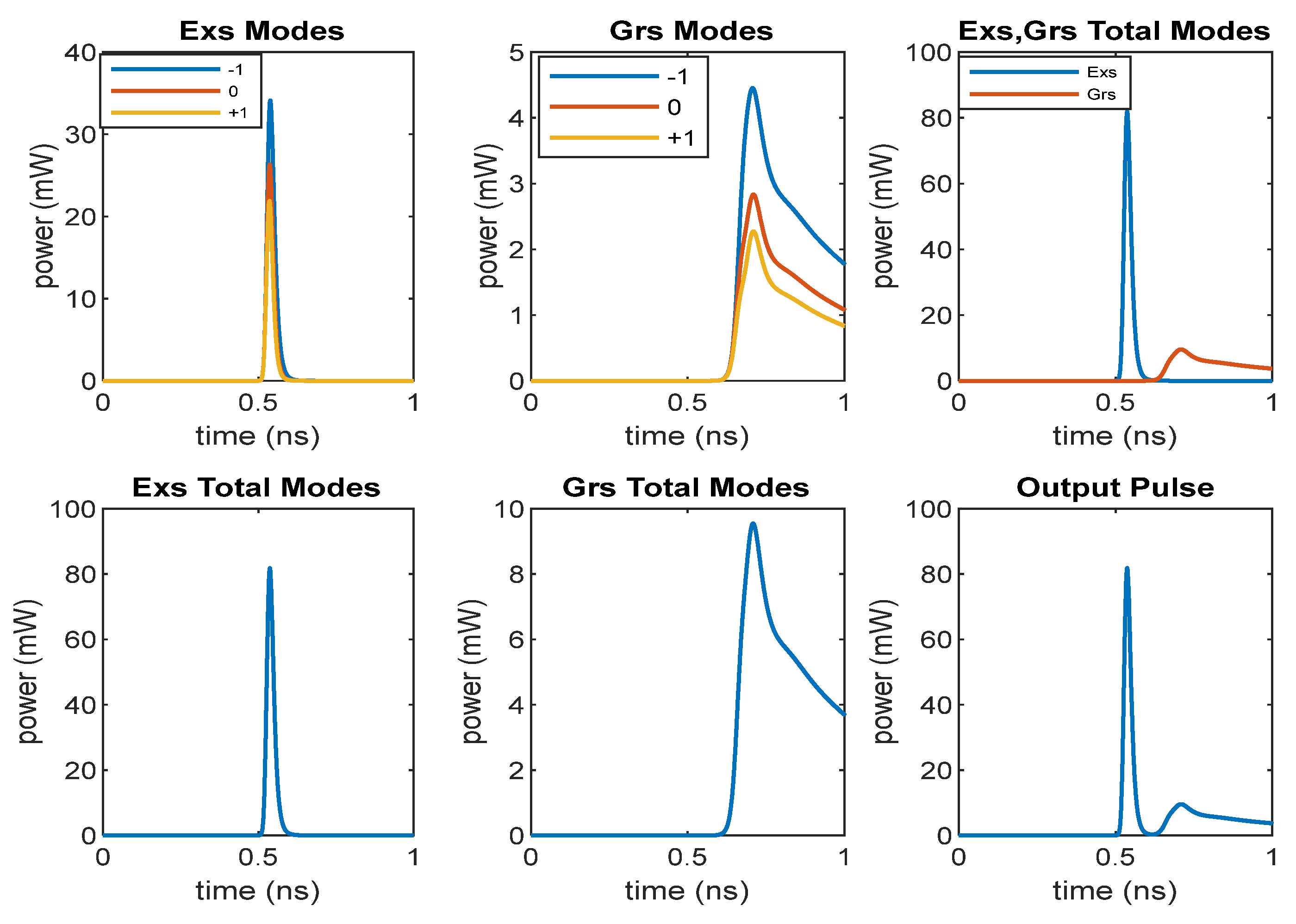
Figure 12 indicates the gain-switched output pulses under the optical beam having a peak power of 10 mW and a width of 10 ps for I
rf of 12 mA. As seen in the figure, Exs emission is dominant over Grs emission, which means the output pulse is generated due to Exs emission. Therefore, the width of the output pulse is narrow (26 ps) and the peak power is high (82 mW) even though the applied current is low. Additionally, the peak power of EOGB must be increased to further increase the peak power of the output pulse.
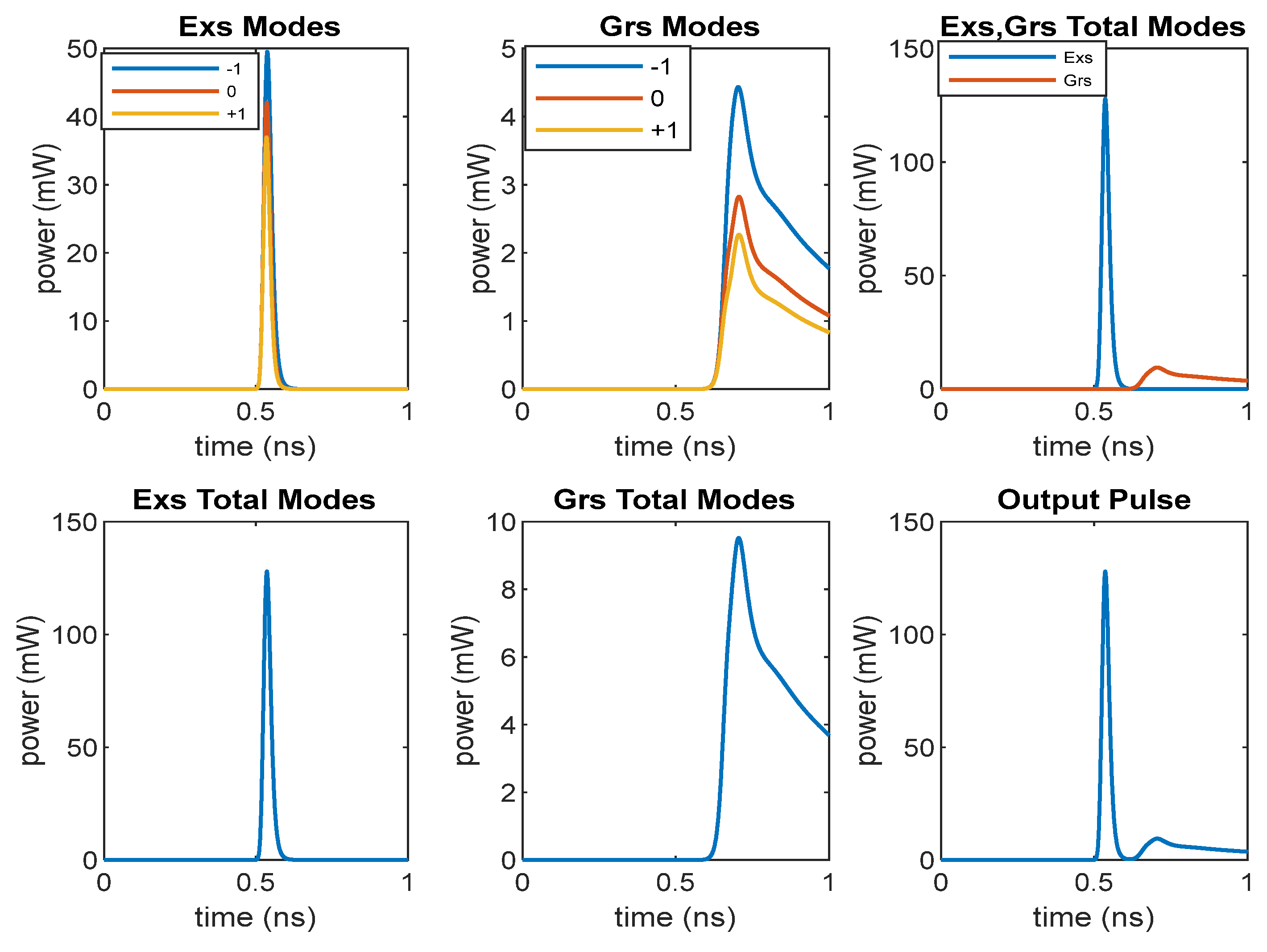
Figure 13 shows output pulses for an optical beam peak power of 20 mW for I
rf of 12 mA. As seen in the figure, while the peak power of the output increases, the width of the output pulse slightly increases and provides a value of 27 ps. Furthermore, according to the applied current, we can adjust the magnitude of the optical beam to obtain short pulses.
It was also found that changes in the laser parameters do not affect the output pulse width and peak power significantly in the presence of the optical beam. However, without EOGB, the output pulses are strongly affected by the change in the laser parameters. Similar results were also obtained for the InAs-InP (113)B quantum dot laser based on single mode rate equations [
26].
Regarding the zero-gain compression factor, our results demonstrated that the behavior of gain-switching characteristics with and without EOGB are similar for liner-gain and nonlinear-gain cases except that higher peak power and narrower output pulses are obtained for the linear-gain case.
As a conclusion, when an EOGB is applied to the Exs, the photon emission of Exs becomes dominant over the Grs, providing shorter output pulses with a high peak power. The Exs emission can be tuned for the C-band optical communication window with proper band energy engineering and growth optimization, such as the double cap procedure [
27,
28].


