Article

Deep Neural Network Memory Performance and Throughput Modeling and Simulation Framework

1
Engineering Faculty, Ruppin Academic Center, Emek Hefer 4025000, Israel
2
Electrical and Computer Engineering Faculty, Technion—Israel Institute of Technology, Haifa 3200003, Israel
*
Author to whom correspondence should be addressed.
Mathematics 2022, 10(21), 4144; https://doi.org/10.3390/math10214144
Submission received: 4 October 2022 / Revised: 25 October 2022 / Accepted: 3 November 2022 / Published: 6 November 2022

Abstract

:
Deep neural networks (DNNs) are widely used in various artificial intelligence applications and platforms, such as sensors in internet of things (IoT) devices, speech and image recognition in mobile systems, and web searching in data centers. While DNNs achieve remarkable prediction accuracy, they introduce major computational and memory bandwidth challenges due to the increasing model complexity and the growing amount of data used for training and inference. These challenges introduce major difficulties not only due to the constraints of system cost, performance, and energy consumption, but also due to limitations in currently available memory bandwidth. The recent advances in semiconductor technologies have further intensified the gap between computational hardware performance and memory systems bandwidth. Consequently, memory systems are, today, a major performance bottleneck for DNN applications. In this paper, we present DRAMA, a deep neural network memory simulator. DRAMA extends the SCALE-Sim simulator for DNN inference on systolic arrays with a detailed, accurate, and extensive modeling and simulation environment of the memory system. DRAMA can simulate in detail the hierarchical main memory components—such as memory channels, modules, ranks, and banks—and related timing parameters. In addition, DRAMA can explore tradeoffs for memory system performance and identify bottlenecks for different DNNs and memory architectures. We demonstrate DRAMA’s capabilities through a set of experimental simulations based on several use cases.

1. Introduction

The usage of deep neural networks (DNNs) is continuously growing in various applications, such as IoT, edge devices, mobile, and high-performance servers in cloud platforms and data centers [1,2,3]. In recent years, DNNs have demonstrated phenomenal prediction and classification capabilities in various applications, including image recognition [4], natural language processing [5], lifelong learning frameworks [6], and recommendation systems [7,8]. DNNs have also been emergingly used for solving complex scientific problems, such as strong-field Feynman’s formulation with preclassification scheme [9]. The authors of [10] studied a denoising method based on DNNs for the vertical seismic profile record received by distributed optical fiber acoustic sensing in seismic exploration. Various methods based on one-dimensional convolutional neural networks and recurrent neural networks for a haze concentration prediction have been studied by [11] and [12], respectively. However, the remarkable accuracy of DNNs comes with a high computational complexity and huge memory system throughput for both network training and inference. These challenges have become major entry barriers for DNNs on various computational platforms due to both the platforms’ limits in performance, cost, and energy and their limited memory system bandwidth.
In recent years, there has been significant growth in the use of dedicated accelerators [13,14], such as systolic arrays (SAs) and graphics processing units (GPUs), which can offer more efficient processing of DNNs than general purpose CPUs. An SA is a spatial computing system that consists of a network of processing elements that rhythmically perform computations and pass data through the system. A GPU is a single instruction multiple data (SIMD) architecture. Similar to SAs, GPUs consist of arrays of processing elements that run the same operation simultaneously; however, GPUs have two fundamental differences from SAs:
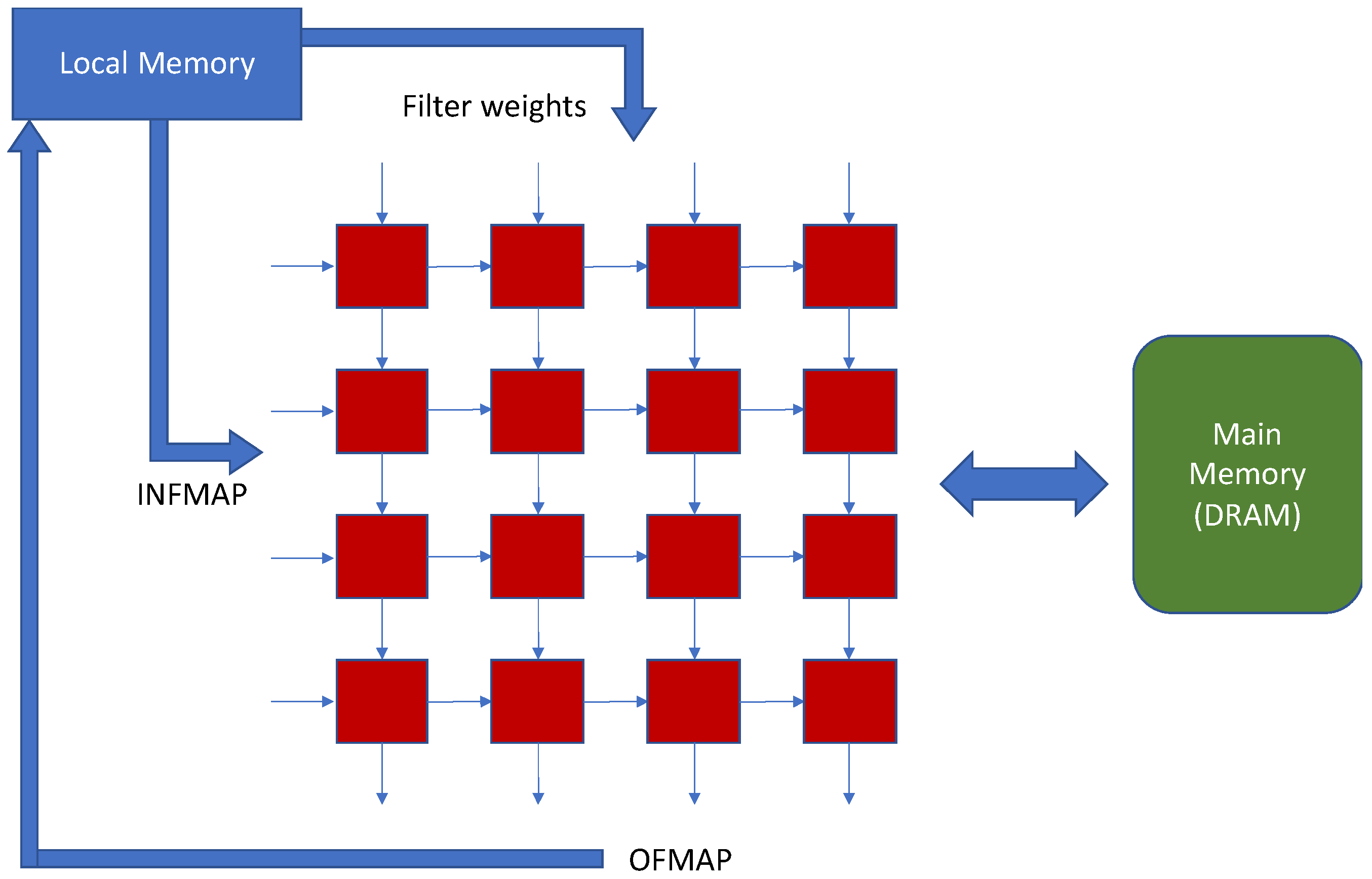
  • While GPU processing elements are programable and execute the same operation simultaneously, SA processing elements can only execute a fixed operation (usually a multiply-and-accumulate).
  • Unlike the SA, however, the processing elements in GPUs cannot pass data directly but, rather, must exchange data via memory. This introduces a major benefit for the SA, since it utilizes memory bandwidth more efficiently.
Both SAs and GPUs are highly dependent on the performance and throughput of their memory systems. This has been further intensified in recent years with advances in semiconductor technologies, which has led to an exponentially growing gap between the speeds of computing elements and memory systems [15].
In this paper, we introduce DRAMA, a deep neural network memory simulator. DRAMA extends the SCALE-Sim [16] simulator, which is commonly used to mimic DNN inference on SAs, with a detailed, accurate, and extensive simulation environment of the associated memory system. SCALE-Sim is a cycle-accurate functional simulator that can process matrix multiplications and convolutions for various DNN architectures. SCALE-Sim allows designers and architects to perform architectural and performance exploration by simulating various DNNs with different SA configurations while considering various system tradeoffs. While SCALE-Sim can accurately model memory accesses performed by the SA to the local memory, it lacks accurate modeling of the main memory system. Due to the growing impact of memory systems on DNN processing performance, it is essential to model the complete memory system accurately. To overcome this issue, DRAMA offers an extension to SCALE-Sim that can simulate the detailed building blocks of main memory, such as memory channels, modules, ranks and banks, and related timing parameters. In addition, DRAMA offers a broad range of configuration parameters that can help in exploring various memory system configuration tradeoffs and identifying bottlenecks for different DNN architectures. This is further demonstrated in Section 4, where we present an architectural exploration for various ResNet-18 [17] memory systems using the DRAMA simulation environment.
We summarize the contributions of this paper as follows:
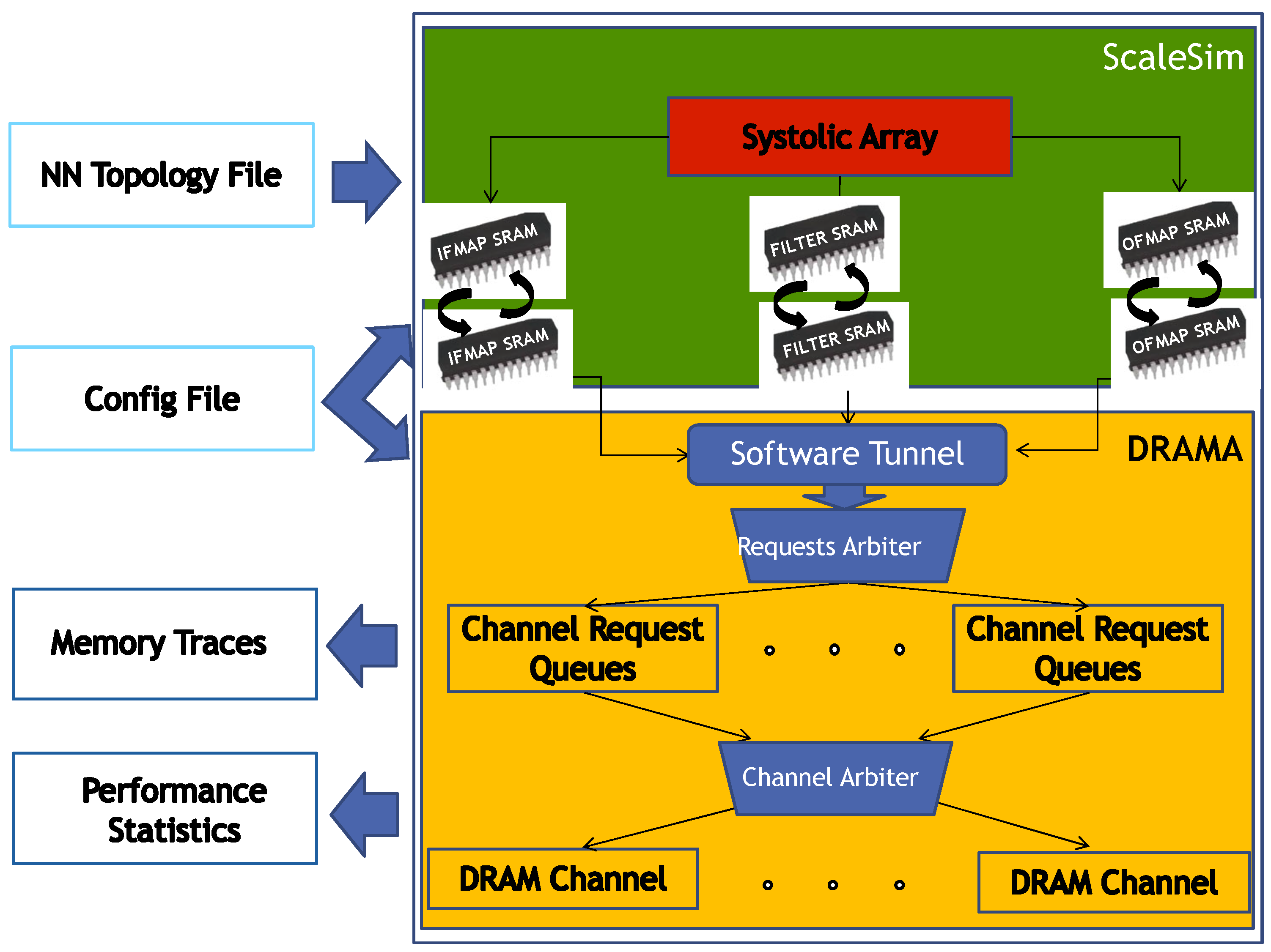
  • We introduce DRAMA, a novel open-source simulation environment that can perform detailed, accurate, and extensive simulation of SA memory systems.
  • DRAMA can run either as an extension to the SCALE-Sim simulator to model the entire memory system accurately or as a standalone main memory simulator.
  • DRAMA offers a broad range of configuration parameters, which can help to perform an accurate memory system exploration for DNNs and to understand the interplay between key memory system parameters.
  • DRAMA generates an accurate main memory trace file that takes into account main memory system configuration and related timing parameters.
  • We demonstrate the impact of memory system parameters on SA performance and memory system throughput through an experimental analysis of several case studies.
The remainder of this paper is organized as follows: Section 2 provides related background and reviews previous work. Section 3 describes the DRAMA simulation environment architecture and flow of operation. Section 4 presents the experimental results. Finally, Section 5 summarizes our conclusions.

2. Background and Prior Works

We start our background discussion by providing an overview on systolic arrays and their memory system. Next, we provide an overview of prior work and, in particular, the SCALE-Sim environment that is extended by this study.

2.1. Systolic Arrays
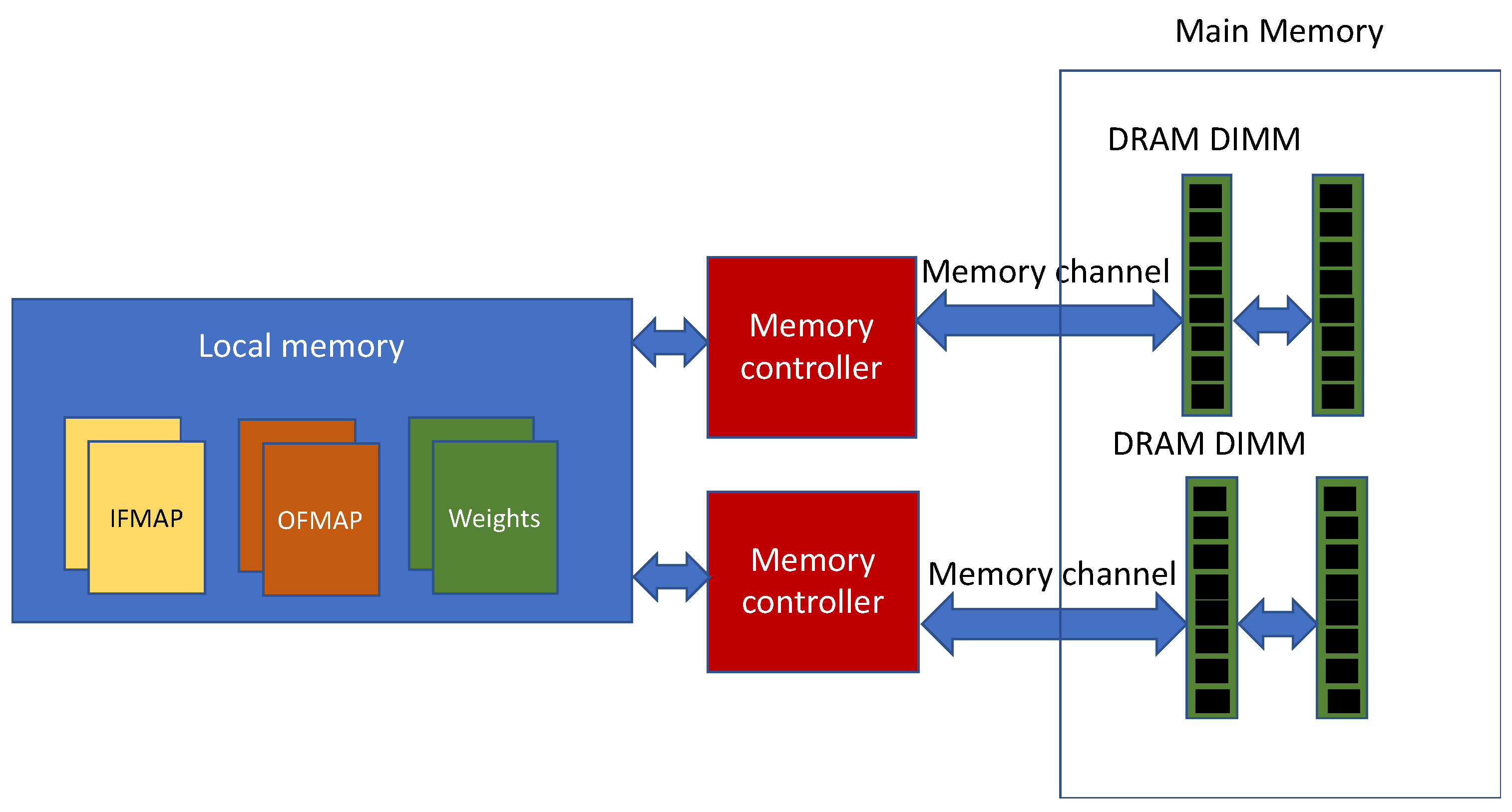
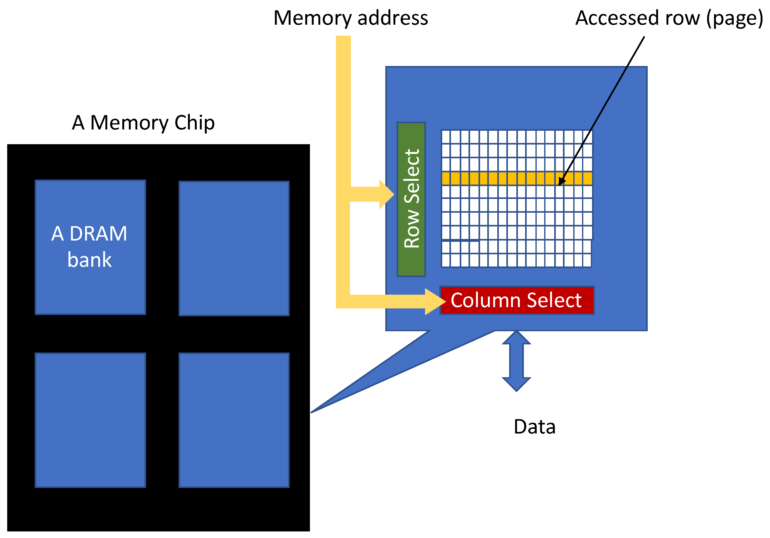
Systolic arrays (SAs) belong to the group of spatial architectures that are commonly used for DNN convolution or general matrix multiplication [1,18]. An SA (illustrated by Figure 1) consists of a two-dimensional mesh array of tightly coupled processing elements (PEs) that can forward data directly between PEs in the same row and column through unidirectional connections. Each PE has an arithmetic logic unit (ALU)—which is typically a multiply-and-accumulate functional unit—and a local storage element that is used to store intermediate computations. Matrix multiplication performed by the SA multiplies the input feature map matrix (INFMAP) by the filter weights and produces the output feature map (OFMAP). The INFMAP and filter weights are read from the SA local memory and the OFMAP is written to the local memory. One of the key advantages of SAs is their mesh structure, which can save a significant number of memory accesses by taking advantage of reusing forwarded data that have been processed by neighboring PEs.

2.2. Memory System

The SA memory system is depicted in Figure 2 and includes three key elements: a local memory, single or multiple memory controllers, and a main memory. The local memory, which is located near the SA, is typically a small and fast memory. The SA continuously accesses the local memory through the process of matrix multiplication. The local memory stores three double buffers (also termed ping-pong buffers) for the IFMAP, OFMAP, and filter weights [1,18]. The double buffers in the local memory allow the SA to execute the matrix multiplication in parallel with fetching the next IFMAP and weights from main memory and writing the previous OFMAP to main memory. All main memory access requests are enqueued onto the memory controller job queue, which manages all read and write access to the main memory [19]. The SA can employ multiple memory controllers, where every controller is connected to a different memory channel. Multiple memory channels can perform parallel memory access operations and, thereby, increase memory bandwidth. Every memory channel consists of one or more dual in-line memory modules (DIMMs). A DIMM consists of multiple memory chips that are soldered to the DIMM. There are two DIMM configurations: a single-rank DIMM and a dual-rank DIMM. In a single-rank DIMM, the memories are soldered onto one side of the DIMM, while, in a dual-rank DIMM, the memories are soldered onto both sides. Using a dual-rank configuration increases the DIMM storage capacity by a factor of two.
The memory chips in DIMMs are dynamic random-access memories (DRAMs) [20], which are slower than the local memory but have a significantly larger storage capacity. As illustrated in Figure 3, every DRAM chip is organized into multiple memory banks. A bank consists of a two-dimensional matrix of memory elements, and each element is uniquely associated with an individual address. Memory elements within the same row have consecutive memory addresses. The memory address provided by the SA for read or write operations is partitioned into a row-select part and a column-select part. The row-select activates access to a single row (also known as a page), while the column-select accesses the particular memory element within the row. Consecutive memory accesses within the same row in a bank can be performed quickly, since the row has been already activated, and the individual memory elements can be directly accessed from the previously read row. This mode of operation is termed fast page mode (FPM). When a new memory access switches to a different row, the time required for the access will become longer, since the new row needs to be activated.
One of the methods of enhancing main memory efficiency is to increase the number of memory banks, since larger numbers of banks will increase the likelihood of FPM access. The number of banks and pages that are available for FPM access in the main memory is given by Equation (1).
Total number of banks = C × D × R × B
where C is the number of memory channels, D is the number of DIMMs, R is the number of ranks, and B is the number of banks.
The efficiency of the memory system is crucial to SA performance and throughput. It is necessary for the next IFMAP and weights to be ready in the local memory before the current matrix multiplication is completed. In addition, the previous OFMAP must also be written to main memory prior to the completion of the SA. If the memory system is a bottleneck, the SA will become stalled.

2.3. SCALE-Sim

SCALE-Sim [16] is a cycle-accurate functional simulator that mimics SA accelerators for DNNs. It can simulate both matrix multiplication and the convolutions that are used by many DNN models. SCALE-Sim allows designers to configure different SA architectures and validate their performance and throughput while considering various tradeoffs. It can also model the memory system in a limited level of a detail. The memory accesses run by SCALE-Sim are limited to the local memory, where it simulates the double buffers of IFMAPs, OFMAPs, and weights. SCALE-Sim generates cycle-accurate read accesses to the local memory, which are required for continuous SA operation. In addition, it accurately models the write accesses that are the outputs of the SA to the OFMAP buffer in the local memory. It should be noted that SCALE-Sim models the main memory using a single configuration parameter that represents the main memory average bandwidth. It does not model the main memory channels, DIMMs, ranks, banks, or the detailed timing parameters related to the main memory. In addition, SCALE-Sim generates trace files, which consist of all memory accesses for IFMAPs, OFMAPs, and weights and can be used for offline processing and analysis of memory traffic. To guarantee continuous operation of the SA, SCALE-Sim also uses the main memory traces to determine whether the prefetching of the data required for the SA operation (INFMAP and weights) and the writing of the previous OFMAP have been completed prior to the next computation task.

2.4. Prior Related Simulation Environments

Memory system simulation environments can be partitioned into three classes: statistical, cycle-accurate, and RTL-based. Statistical simulators typically use a statistical model for the memory system latency [21,22,23]. Such simulators offer the advantage of a high simulation speed; however, they incur a lack of accuracy, which can vary significantly between different use cases. The authors of [21] approached DRAM latency modeling into a classification problem and used machine learning models for predicting the DRAM access time. They used synthetic traces to train their machine learning model and validated their results on several benchmarks. The authors of [23] suggested an abstract, cycle-approximate transaction-level model of a DRAM memory controller for virtual prototyping. Their model extracts the timing behavior from hardware description language simulation and creates a conditional distribution function that is used by the transaction-level model.
Cycle-accurate simulators accurately model the memory system but at the cost of longer execution time. In recent years, several cycle-accurate DRAM simulators have been developed for general applications [24,25,26,27,28,29,30]. These simulators are tightly coupled to the evolving DRAM JDEC standard, and some of them are also tightly coupled to general-purpose single-core and multi-core CPU simulators [31,32,33]. DRAMSim2 is a common DRAM simulator, which was introduced by [24]. DRAMSim2 is a cycle-accurate DDR2/3 DRAM simulator that is aimed to provide an integration model for DRAM memory model. The simulator can measure a single DRAM channel performance and also includes a verification tool to validate the results of simulation in conjunction with a visualization tool. DRAMSim3 is a successor to DRAMSim2 and is capable of supporting configurable DRAM parameters. The simulator employs system-level interfaces to interact with a CPU simulator, such as gem5 [31] or a trace frontend. In addition, it can run thermal and power modeling. Ramulator [26] is a cycle-accurate DRAM simulator that supports various DRAM standards, such as DDR3 and DDR4. Ramulator can be run in two different modes: as a standalone simulator or as an integrated framework with gem5. The simulator is built as a hierarchy of state machines, where each state machine is defined by the supported DRAM standard. DrSim [27] is a cycle-accurate DRAM simulator that is similar to DRAMSim2. The simulator can also run as a standalone simulator or integrated with gem5. DrSim can simulate controller policies and various DRAM organizations and timing parameters. USIMM simulator was introduced by [28] and is mainly focused on the memory accesses scheduling rather than DRAM subsystem architecture. Gem5 [31] is a full CPU and memory system simulator, which includes cache hierarchy and DRAM memory controller. DRAMSys 3.0 simulator was introduced by [29] and offered a design exploration framework for different design parameters, such as power, errors, compliance, waveform generation, and bus monitoring. DRAMsys 3.0 modeled a single memory controller and a DRAM memory that complied with one of the supported standards (e.g., DDR3 or DDR4). The authors of [22] extended DRAMSys using a lookup table to speed up simulation time for dense memory traces. Their tool focused on DRAM latency estimation based on a neural network. DRAMSys4.0 [30] is a revised version of DRAMSys3.0 that supports the latest DRAM standards, such as DDR5. DRAMSys4.0 can operate as a standalone simulator with trace players, a gem5-coupled simulator, and a TLM-AT-compliant library. The simulator is also equipped with a trace analyzer for DRAM subsystem design space exploration. RTL-based simulators [34] use hardware description languages (HDLs) to accurately simulate DRAM controllers and memory system elements; however, they suffer from a lack of scalability and require long simulation times. Table 1 summarizes all related works and presents their simulation scope, memory system level modeling, DRAM technology, and simulation method. The proposed DRAMA simulation environment offers the following strengths with respect to the prior works:
  • DRAM can be integrated with SA simulators, such as SCALE-Sim.
  • While many of the existing simulators are tightly coupled to specific standards, DRAMA allows flexible memory system configuration.
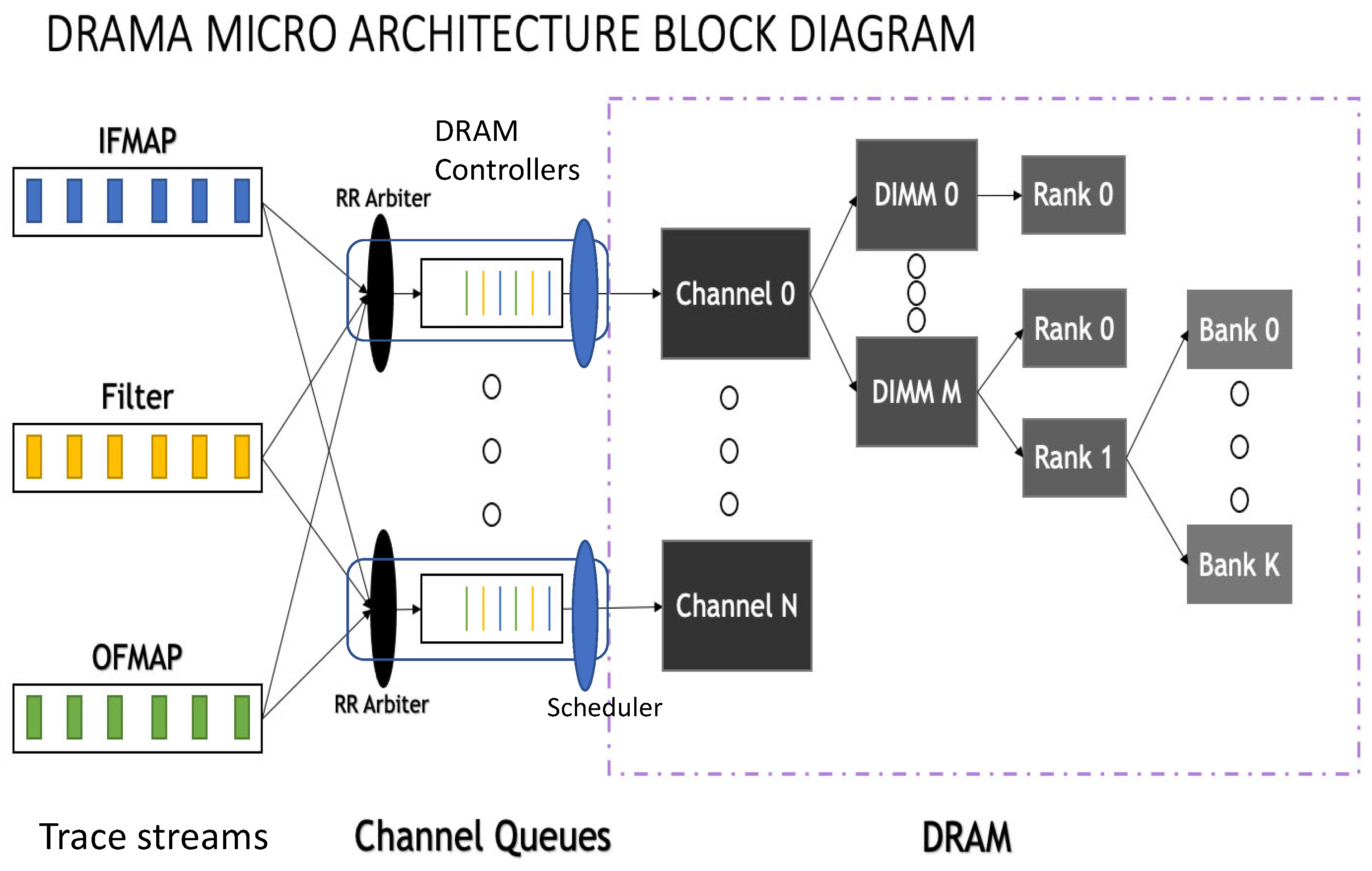
  • DRAMA supports multiple memory channels topology, while many of the prior work simulation environments are limited to a single channel or a single DRAM.

3. DRAMA Simulation Environment Framework

In this study, we present DRAMA, a deep neural network memory hierarchy simulator. DRAMA offers a plug-and-play extension to the SCALE-Sim simulator and can either be simply integrated with other DNN simulators or run as a standalone simulator. DRAMA offers a highly configurable simulation environment, which can be very useful for system architects to explore different memory hierarchies, topologies, and related parameters and tune overall SA and memory system performance. DRAMA is designed in python and is provided as open-source code in GitHub (https://github.com/DRAMA-technion/DRAMA (accessed on 5 November 2022)). We start by introducing DRAMA operation flow, describe its architecture, and discuss the implementation details. Next, we present DRAMA’s configuration settings and, finally, we describe the details of the simulator outputs.

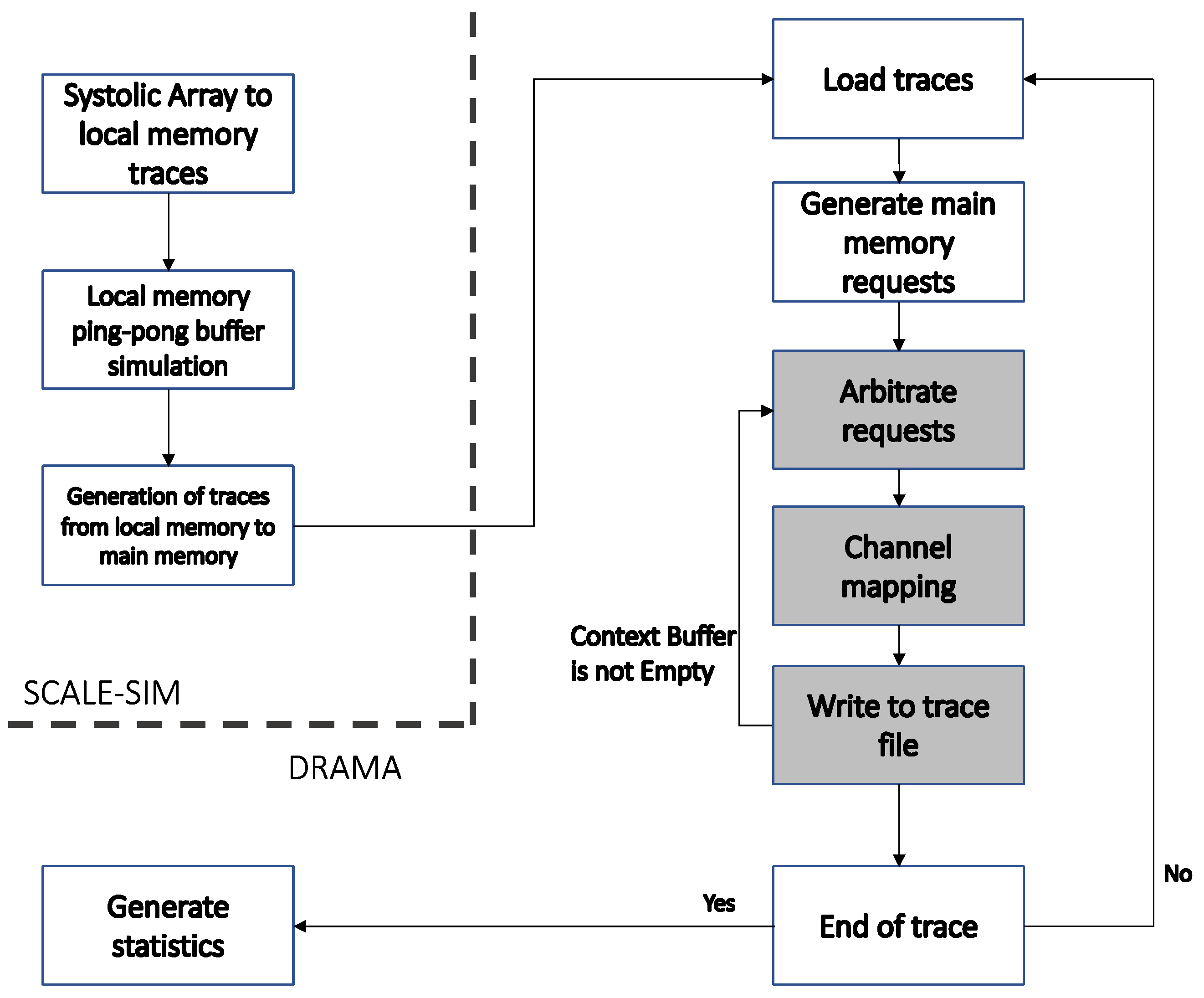
3.1. DRAMA Architecture

Figure 4 and Figure 5 illustrate DRAMA’s operation flow and block diagram, respectively, in conjunction with SCALE-Sim. The block diagram and flow represent the software implementation of DRAMA (the hardware representation of DRAMA is illustrated in Figure 6). SCALE-Sim simulation consists of three main functions:
  • A simulation of the SA processing and generation of local memory access traces.
  • A simulation of the requests targeted to the local memory ping-pong buffers.
  • Generation of the trace to the main memory for prefetching the next INFMAPs and filter weights and for writing the previous OFMAPs.
As illustrated in Figure 5, SCALE-Sim reads the topology parameters of the neural network from the topology file [16]. The file specifies the number of layers and type, INFAMP dimensions, and filter dimensions. The configuration file, which will be described later, is used to specify the simulation parameters for both SCALE-Sim and DRAMA.
As part of DRAMA’s software architecture, we have designed a software interface such that all main memory access traces from SCALE-Sim are channeled into DRAMA. This software interface allows co-simulation of DRAMA and SCALE-Sim to take place simultaneously. DRAMA reads the main memory traces and generates main memory requests, which are forwarded to the detailed main memory simulation engines. The requests, which are initiated by different sources (INFMAPs, filter weights, and OFMAPs), are arbitrated by the request arbiter and are enqueued to one of the main memory channel queues. The mapping is performed such that every memory region (defined by start address and end address) is mapped to an individual channel. Then, all accesses in the queues are arbitrated by the channel arbiter. For every request that is scheduled for main memory access, DRAMA performs the following actions:
  • It calculates the overall time required by the DRAM channel to serve the request.
  • It updates the simulator performance statistics counters.
  • It removes the request from the channel queue.
Once the request processing is complete, the main memory access details are written to the trace file. This process is repeated for as long as there are access requests in the channel queue. Once the requests in all queues have been processed, the simulator checks whether additional traces have been generated. If there are new main memory access traces, the process will be repeated, as illustrated in Figure 4; otherwise, the simulation will be terminated and DRAMA will generate the simulation statistics. DRAMA simulation outputs are described in detail in Section 3.3.
The main memory system hardware architecture that is simulated by DRAMA is illustrated in Figure 6. The system consists of a set of DRAM controllers, where each controller is assigned to an individual DRAM channel. Each DRAM controller compromises:
  • An arbiter, which arbitrates the stream of memory requests destined for the DRAM channel. The arbiter operates in a round-robin (RR) manner and adds the requests to the request queue.
  • A request queue, which includes all pending requests. The queue is managed in a first-in-first-out (FIFO) manner.
  • A scheduler, which schedules the request in the head of queue to be served by the DRAM channel as soon as it becomes available. The scheduler removes the served request from the memory controller queue.
The DRAM channel topology can be viewed as a tree structure. Every channel consists of multiple DIMMs of single or dual rank. All memory chips in a rank operate as a single logical memory, which is partitioned into multiple banks. The number of channels, DIMMs, ranks, and banks are specified in the configuration described in Section 3.2.

3.2. DRAMA Configuration Settings

The configuration file is parsed by the DRAMA simulator and is used to specify the detailed architecture of the main memory system. The configuration file, which is summarized in Table 2, specifies the number of DRAM channels and size, the number of DIMMs per channel, the DIMM ranks, the number of banks, and the page size. In addition, it defines the memory channel data bus width and the DRAM timing parameters. The configuration also specifies the method of mapping memory addresses to DRAM channels. The mapping can be conducted using either the least significant or most significant bits of the address. In the former, consecutive memory addresses are mapped to different memory channels. In the latter, the entire memory space is partitioned into multiple windows, where each is associated with an individual memory channel.
Finally, the configuration file specifies row, column, and bank mappings within a channel using two common methods—row interleaving and cache line interleaving—which are illustrated in Figure 7. In row interleaving, consecutive accesses are mapped to consecutive banks, while cache line interleaving maps consecutive cache blocks to consecutive memory banks [35].

3.3. DRAMA Outputs

The simulation performed by DRAMA produces two output files: a statistics summary file and a trace file. The statistics summary file summarizes for every convolution or matrix multiplication task the following performance-related statistics of every channel in the memory system:
  • Channel memory bandwidth, measured in bytes per cycle.
  • Average number of clock cycles per memory request.
  • The percentage of time the SA was idle.
  • The total number of pages open in a DRAM channel.
  • Busy cycles—the number of cycles when the memory channel was busy.
  • Total number of requests.
  • Total number of bytes read by the SA.
The trace file is a csv file where every line lists the addresses of the main memory prefetch accesses and their accurate occurrence time. DRAMA’s trace file extends the traces generated by SCALE-Sim by performing a detailed simulation of the main memory system. In particular, the timing annotation in every line takes into account the overall memory system configuration and related timing parameters.

4. Experimental Results and Discussion

Our experimental analysis demonstrates the capabilities of the DRAMA simulation environment for various computational workloads and use cases. The presented experiments are mainly focused on the impact and contribution of the memory system and its impact on overall SA performance.

4.1. Experimental Use Case

The use case for our experimental study is the ResNet-18 convolutional neural network [17]. ResNet-18 is 18 layers deep and is commonly used for image classification tasks. ResNet-18 can classify images into 1000 object categories. As part of the experimental use case, we have chosen four different convolution layers from ResNet-18, which are presented in Table 3. Each of the chosen layers has multiple repetitions in the network, so they fairly represent the overall network workload.
Our experimental exploration examines three use cases—the DRAM bandwidth, the number of memory channels, and the ratio of closed page to open page access latency—on overall SA performance and memory system throughput. The results are presented and discussed in Section 4.2.

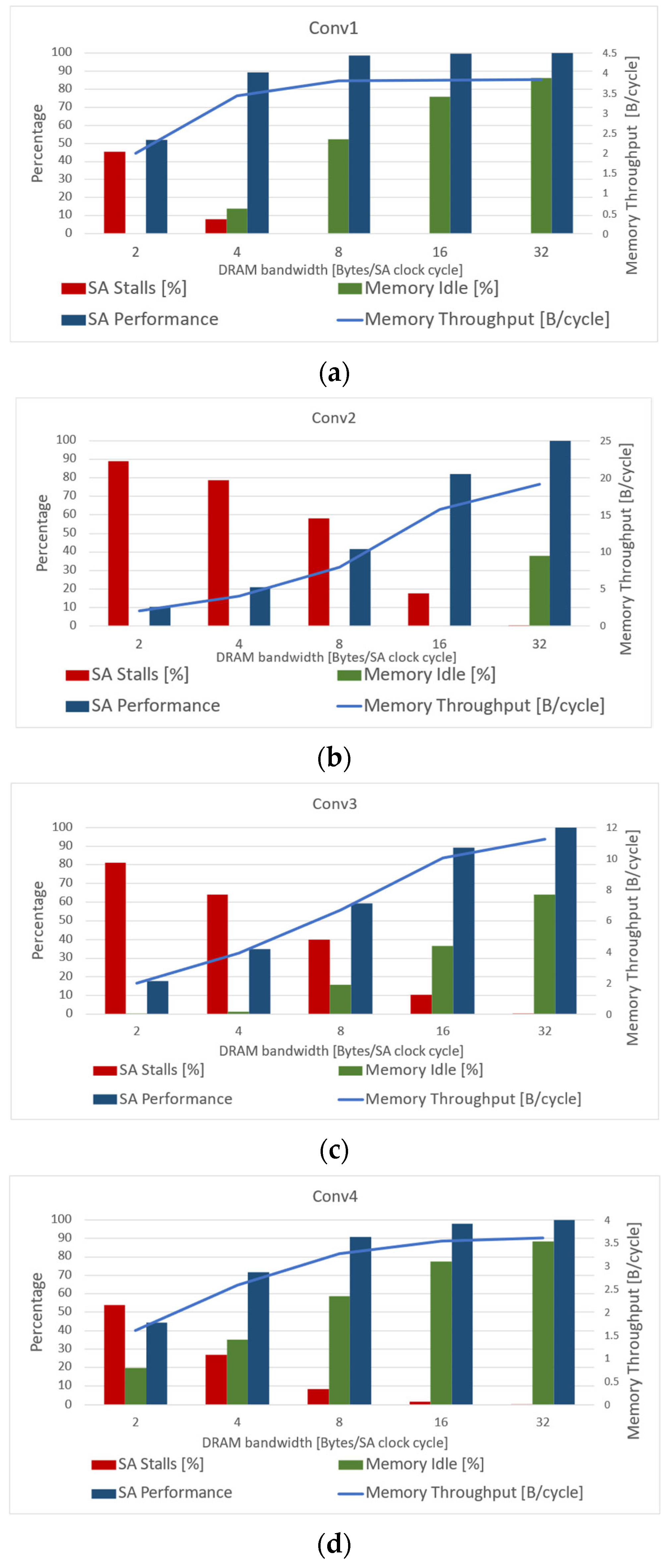
4.2. Case Studies Analysis

In the first use case, we examine the impact of DRAM bandwidth on a single-channel memory system with eight DIMMs and eight banks in every DIMM. The channel mapping is based on row interleaving, and the page size is 4096 bytes. The experiments examine DRAM bandwidths of 2, 8, 16, and 32 bytes per SA clock cycle. The SA dimension used in our simulations is 16 × 16, which runs output stationary dataflow. Figure 8 illustrates simulation results for the four convolution layers in Table 3. The experimental results measure the percentage of time the SA was stalled, the percentage of time the memory system was idle, the SA relative performance (compared to an ideal SA with an ideal memory system), and the memory system’s overall throughput. It can be seen that, as the DRAM bandwidth increases, the percentage of time the SA is stalled decreases. This is due to the fact that all main memory accesses are performed in batches, which are initiated by the ping-pong buffers (in the local memory) of the IFMAPs, filter weights, and OFMAPs. All main memory batches are constrained in time. A main memory batch can be started as soon as buffers are switched by the ping-pong buffers and must be completed before the SA starts the next batch when the ping-pong buffers are switched again. If main memory batches cannot be handled in the needed deadline of the SA, the SA will be stalled. The pipeline process of the SA and the main memory system is illustrated in Figure 9 and provides a further insight to the relation between the main memory system bandwidth and the SA throughput. When the main memory system throughput is increased, it is more likely that the SA will have the needed data to start the next batch on time and avoid any stalls. If the main memory system handles the batches before the SA deadline, it increases the idleness of the memory system, as illustrated in Figure 9.
Figure 8a–d performance measurements show that the SA relative performance is inversely correlated with the SA stalls: once the number of SA stall clock cycles drops to 0, the SA relative performance reaches 100%. The results also indicate that, as we increase the DRAM available bandwidth, the overall memory system throughput utilized by the SA grows. This, however, may increase the percentage of time the memory system is idle (as illustrated in Figure 9). In certain cases, we observe that, although the memory system is idle for a certain amount of time, there are still stalls in the SA. This is because the DRAM access takes longer whenever a new page is accessed and, as a result, the DRAM is idle till the new data are accessed and delivered to the SA. Another cause for this phenomenon is the fact that some of the main memory batch accesses miss the SA deadline and, as a result, the SA will be stalled.
Another important observation that is obtained from Figure 8 indicates that different convolution layers introduce diverse memory throughput requirements. For example, for conv1, a DRAM bandwidth of 8 bytes per clock cycle is sufficient to eliminate the SA from stalling, while conv2, conv3, and conv4 require 32 bytes per cycle to avoid SA stalls. Figure 8 also presents the required bandwidth by every convolution layer to eliminate SA stalls: conv1, conv2, conv3, and conv4 require approximately 3.8, 19, 11, and 3.5 Bytes per clock cycle, respectively. This is explained by the fact that every coevolution layer involves different main memory batch size. Our experimental measurements indicate that conv1 batch size is 1.51 Mbytes, while conv2, conv3, and conv4 batch size is 7.25 Mbytes, 3.5 Mbytes, and 1.81 Mbytes, respectively. The reason conv1 batch size is significantly smaller is due to the fact that it is able to better utilize the local SA memory and, thereby, it requires a smaller amount of data to be fetched from main memory. It can be observed in Table 3 that the number of channels increases by x2 as we move to deeper convolution layers, while the filter size remains unchanged (3 × 3). The increasing number of channels encourages more frequent swaps in the local memory ping-pong buffer and, as a result, a large amount of data is needed to be prefetched from main memory. The required memory throughput measurements found by our experimental analysis can be compared to similar measurements reported in [16]. Although [16] used different DNNs, the most similar DNN we can compare our DNN to is ResNet-50. The required memory throughput reported by [16] for ResNet-50 is in the range of 4–27 Bytes per clock cycle, which is similar to the measurements in our simulations.
In the second use case, we examine the impact of the number of channels and the channel mapping on the SA performance and memory system throughput. We run the simulations with one, two, and four memory channels, where the two- and four-channel cases have each been run using the two different channel mapping options—using either the least significant bits (LSB) of the memory address or the most significant bits (MSB). The memory system configuration assumes a DRAM bandwidth of 16 bytes per SA clock cycle and a total of four DIMMs with eight banks per DIMM. The page size is 2048 bytes and the address mapping is row interleaving.
Figure 10 summarizes the simulation results for all the convolution layers in Table 3. It can be seen that, when increasing the number of channels, the overall main memory system bandwidth is increased, the SA performance is improved, and the number of SA stalls is reduced. In addition, it can be observed that LSB channel mapping achieves better performance than MSB channel mapping for all convolution layers. A deeper insight into the principles of channel mapping operation is illustrated in Figure 11. The LSB mapping improves the main memory throughput at batch level. This improvement is achieved due to the fact that consecutive memory accesses within a batch are mapped to different memory channels. As a result, the effective throughput for a batch is increased by a factor of the number of channels. On the other hand, MSB mapping is useful when batches are mapped into different channels and, as a result, it reduces the likelihood of batch conflicts. The insight into the mechanisms of channel mapping explains the experimental results presented in Figure 10, where it is clearly observed that the four memory channels with LSB mapping achieves the best performance in all convolution layers. The speedup in the overall batch access time enables the SA to reach the maximum possible performance. The most noticeable speedup in the SA performance is achieved in the conv1 and conv2 layers, since, in this use case, they require the highest memory bandwidth in order to avoid SA stalls (as illustrated in Figure 10). In this case, the four channels with LSB mapping gains over 40% improvement in SA performance relative to a single memory channel. When the number of channels increases, this not only helps improve the SA performance, but also increases the overall memory system performance. The total number of bytes prefetched from the system remains the same regardless of the number of channels; however, as the number of channels increases, the overall memory access time becomes smaller and, thereby, the throughput is improved significantly. The experimental results reported for this use case correspond to prior studies in other applications, such as [36], where the authors have analyzed the performance of different multithreaded benchmarks for multi-channel DRAM. Their study has reached similar conclusions, indicating that consecutive memory accesses benefit from the multi-channel DRAM rather than arbitrary random accesses.
In the last use case, we study the impact of the ratio of the access latency of a closed DRAM page to the access time of an open page. Our experiments assume a single-channel memory system with four DIMMs and four banks in every DIMM. The memory system bandwidth is 16 bytes per SA clock cycle, the bank mapping is based on row interleaving and the page size is 256 bytes.
Figure 12 summarizes the simulation results for all the convolution layers in Table 3. It can be observed that, as the ratio of closed-page access time to open-page access time increases, the main memory throughput decreases alongside an increase in SA stalls and decrease in the percentage of time the memory system is idle. This is due to the fact that, the longer it takes to access a closed page, the effective main memory throughput decreases, i.e., the handling of batches takes longer and the likelihood of the main memory system to meet the SA deadline decreases.

5. Conclusions

DNN processing introduces not only major computational complexity, but also continuously growing memory throughput requirements. Memory systems have a crucial impact on DNN processing performance and, thus, it is essential to accurately model them when exploring various DNN architectures and system configurations in simulation environments. We summarize the merit of this paper as follows:
  • We introduced a DRAMA simulation environment that can accurately perform detailed main memory system simulation of DNNs. DRAMA can accurately model main memory channels, DIMMs, ranks, banks, and related timing parameters.
  • DRAMA can measure memory system throughput, SA throughput, idle time of both SA and memory system, and memory system average access latency.
  • DRAMA is an open-source tool written in python and can be seamlessly integrated into other simulation environments or operate as a standalone simulator. DRAMA is designed in a modular manner offering a scalable and configurable simulation platform. It can be extended or adjusted to comply with various memory systems models, such as CPUs or GPUs, in order to examine the interplay between key memory system parameters.
  • DRAMA can generate an accurate main memory trace file that can help system debugging and performance tuning by presenting the sequence of memory system events and their relation to the processing performed by the SA.
The presented framework has the following limitations, which may be further addressed by future works:
  • The DRAMA simulation environment does not currently support emerging memory technologies, such as high bandwidth memories (HBM) [37], nonvolatile DIMMs [38], and phase-change memory (PCM) [39].
  • The impact of the main memory system on the inference latency is out of the scope of this study. Our main focus in this study is on the main memory throughput and its impact on the SA throughput.
  • The modeling of the main memory system accesses through DNN training is beyond the framework of this study. This limitation is due to the fact that SCALE-Sim can simulate inference only.
We have demonstrated DRAMA’s capabilities on four representative convolution layers from ResNet-18, where we examined the effects of DRAM bandwidth, the ratio of the access latency of a closed DRAM page to the access time of an open page, number of channels, and bank mapping on SA performance and memory system throughput. We summarize our experimental conclusions as follows:
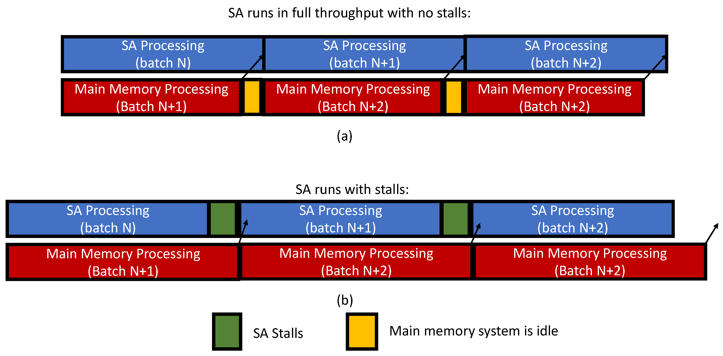
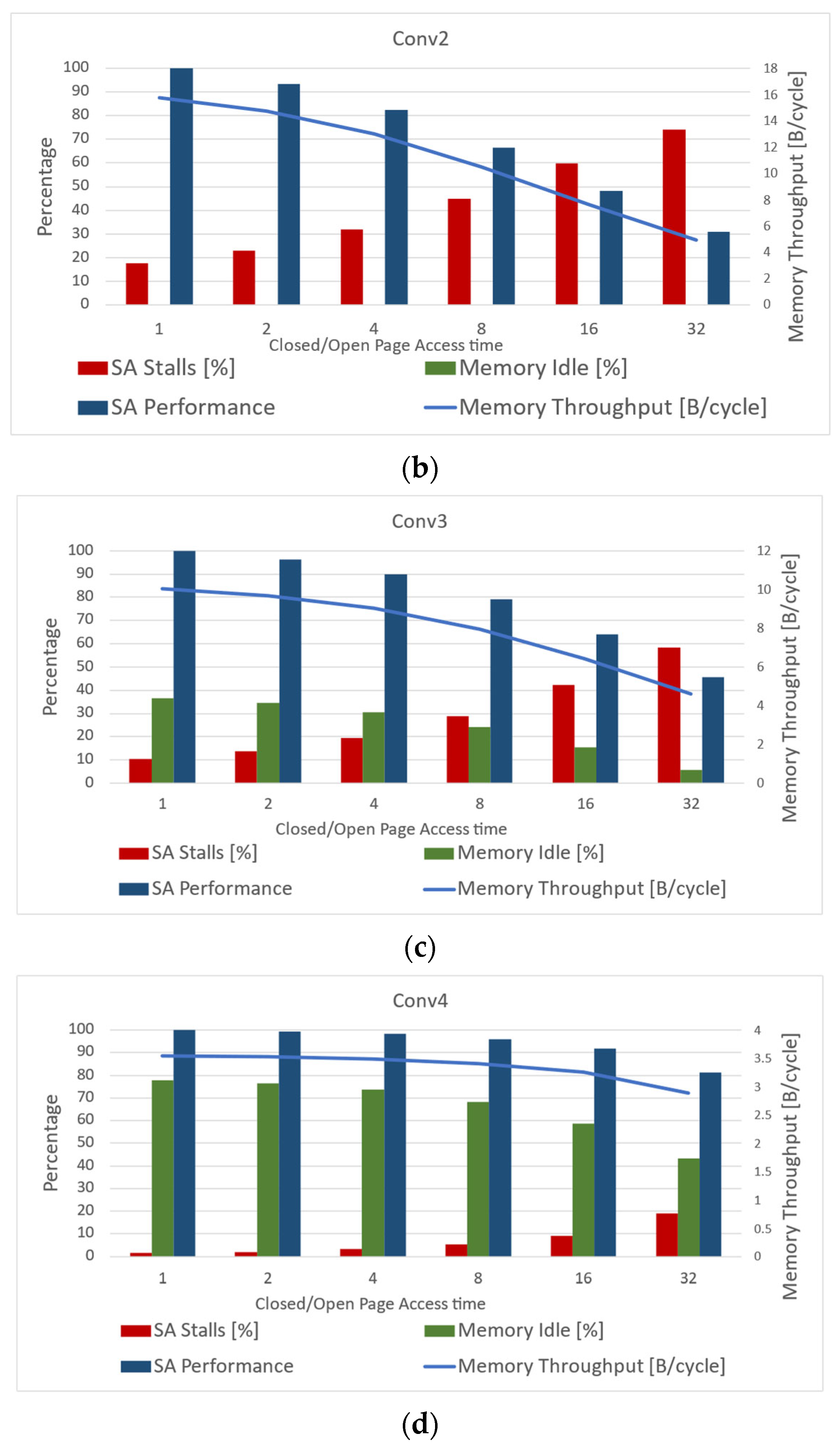
  • As the DRAM bandwidth increases, the percentage of time the SA is stalled decreases. This finding is governed by the SA timing constraints that allow main memory batch to be started as soon as the ping-pong buffers are switched and must be completed before the SA starts the next batch. The increase in the main memory throughput increases the likelihood that the memory system will meet the SA deadline.
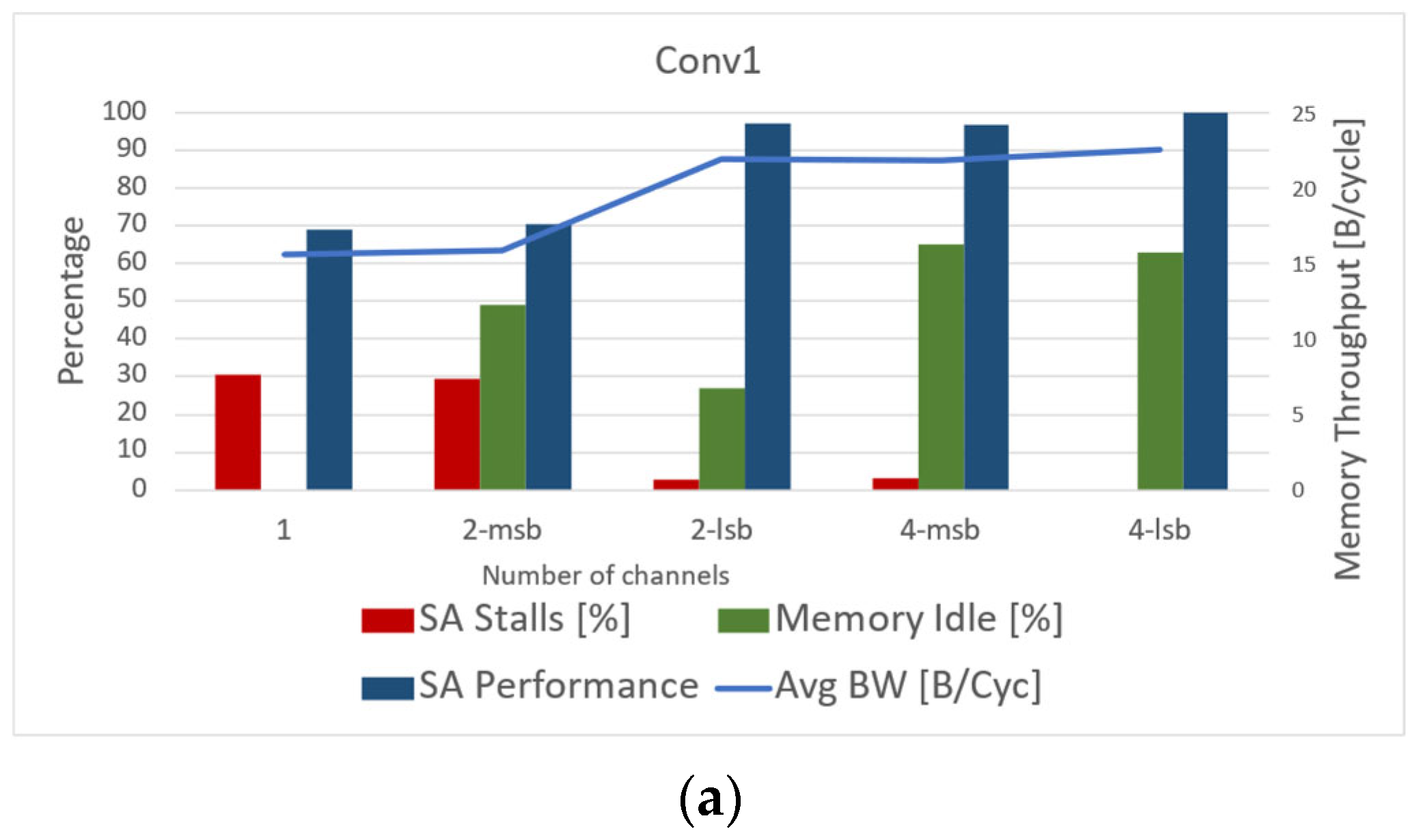
  • Different convolution layers introduce diverse memory system requirements. When a convolution layer is able to better utilize the local SA memory, it can employ a significantly smaller main memory batch. In addition, when the increasing number of channels encourages more frequent swaps in the local memory ping-pong buffer, a large amount of data is needed to be prefetched from main memory.
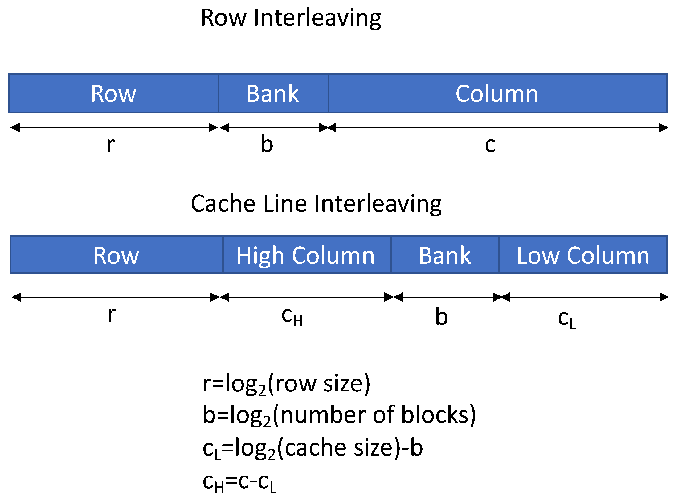
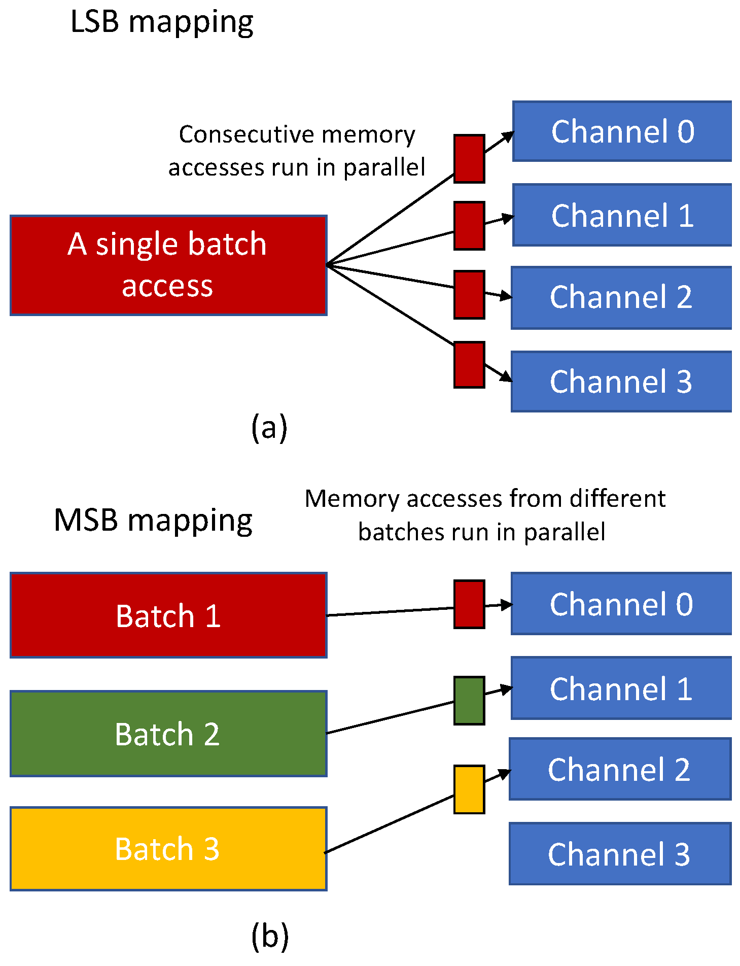
  • LSB bank mapping improves the main memory throughput at batch level, while MSB mapping is useful when batches are mapped into different channels, and, as a result, it reduces the likelihood of batch conflicts.
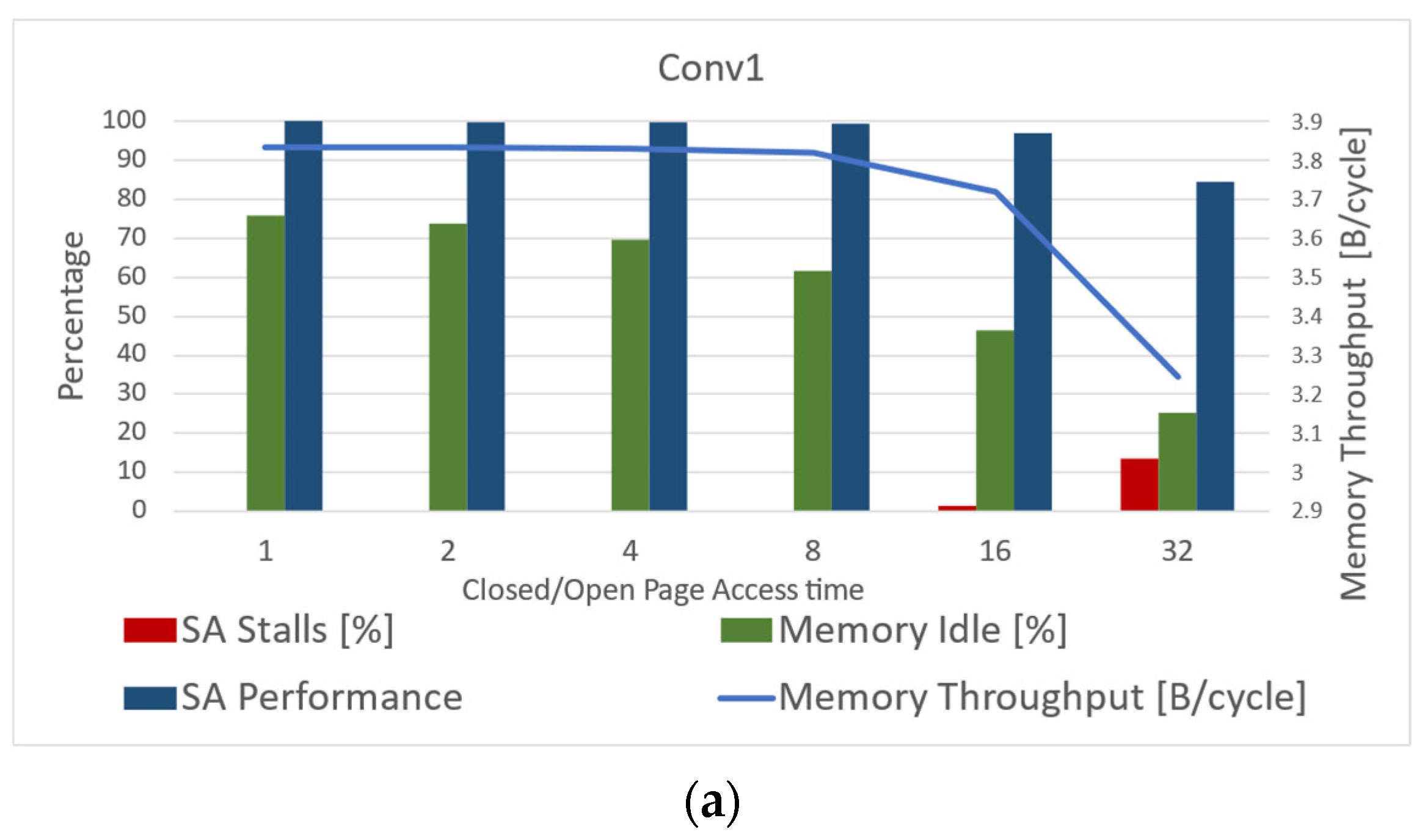
  • As the ratio of closed-page access time to open-page access time increases, the main memory throughput decreases. This is due to the fact that the longer it takes to access a closed page, the likelihood of the main memory system to meet the SA deadline decreases.
Our simulation results emphasize the importance of incorporating the memory system into DNN performance simulations. This is essential for accurate modeling of the full system and in order to explore tradeoffs for memory system performance and identify bottlenecks for different DNNs and memory architectures.

Author Contributions

Conceptualization, F.G.; methodology, F.G.; software, O.S. and R.L.A.; validation, F.G., O.S. and R.L.A.; formal analysis, F.G., O.S. and R.L.A.; investigation, F.G.; resources, F.G.; data curation, F.G.; writing—original draft preparation, F.G.; writing—review and editing, F.G.; visualization, F.G., O.S. and R.L.A. All authors have read and agreed to the published version of the manuscript.

Funding

This research received no external funding.

Informed Consent Statement

Not applicable.

Data Availability Statement

The DRAMA simulator code is available as open source available at: https://github.com/DRAMA-technion/DRAMA (accessed on 10 September 2022).

Conflicts of Interest

The authors declare no conflict of interest.

References

  1. Sze, V.; Chen, Y.; Yang, T.; Emer, J.S. Efficient Processing of Deep Neural Networks: A Tutorial and Survey. Proc. IEEE 2017, 105, 2295–2329. [Google Scholar] [CrossRef] [Green Version]
  2. LeCun, Y.; Bengio, Y.; Hinton, G. Deep learning. Nature 2015, 521, 436–444. [Google Scholar] [CrossRef] [PubMed]
  3. Esteva, A.; Kuprel, B.; Novoa, R.A.; Ko, J.; Swetter, S.M.; Blau, H.M.; Thrun, S. Dermatologist-level classification of skin cancer with deep neural networks. Nature 2017, 542, 115–118. [Google Scholar] [CrossRef] [PubMed]
  4. Krizhevsky, A.; Sutskever, I.; Hinton, G.E. ImageNet classification with deep convolutional neural networks. In Proceedings of the 26th Annual Conference on Neural Information Processing Systems 2012, Lake Tahove, NV, USA, 3–6 December 2012; pp. 1097–1105. [Google Scholar]
  5. Collobert, R.; Weston, J.; Bottou, L.; Karlen, M.; Kavukcuoglu, K.; Kuksa, P. Natural language processing (almost) from scratch. J. Mach. Learn. Res. 2011, 12, 2493–2537. [Google Scholar]
  6. Sun, G.; Cong, Y.; Wang, Q.; Zhong, B.; Fu, Y. Representative Task Self-Selection for Flexible Clustered Lifelong Learning. IEEE Trans. Neural Netw. Learn. Syst. 2022, 33, 1467–1481. [Google Scholar] [CrossRef]
  7. Covington, P.; Adams, J.; Sargin, E. Deep neural networks for YouTube recommendations. In Proceedings of the 10th ACM Conference on Recommender Systems 2016 (RecSys’16), Boston, MA, USA, 15–19 September 2016; Association for Computing Machinery: New York, NY, USA; pp. 191–198. [Google Scholar] [CrossRef] [Green Version]
  8. Zhang, M.; Chen, Y.; Lin, J. A privacy-preserving optimization of neighborhood-based recommendation for medical-aided diagnosis and treatment. IEEE Internet Things J. 2021, 8, 10830–10842. [Google Scholar] [CrossRef]
  9. Liu, X.; Zhang, G.; Li, J.; Shi, G.; Zhou, M.; Huang, B.; Tang, Y.; Song, X.; Yang, W. Deep Learning for Feynman’s Path Integral in Strong-Field Time-Dependent Dynamics. Phys. Rev. Lett. 2020, 124, 113202. [Google Scholar] [CrossRef] [Green Version]
  10. Zhong, T.; Cheng, M.; Lu, S.; Dong, X.; Li, Y. RCEN: A Deep-Learning-Based Background Noise Suppression Method for DAS-VSP Records. IEEE Geosci. Remote Sens. Lett. 2022, 19, 3004905. [Google Scholar] [CrossRef]
  11. Zhang, Z.; Tian, J.; Huang, W.; Yin, L.; Zheng, W.; Liu, S. A Haze Prediction Method Based on One-Dimensional Convolutional Neural Network. Atmosphere 2021, 12, 1327. [Google Scholar] [CrossRef]
  12. Shang, K.; Chen, Z.; Liu, Z.; Song, L.; Zheng, W.; Yang, B.; Liu, S.; Yin, L. Haze Prediction Model Using Deep Recurrent Neural Network. Atmosphere 2021, 12, 1625. [Google Scholar] [CrossRef]
  13. Jouppi, N.P.; Young, C.; Patil, N.; Patterson, D.; Agrawal, G.; Bajwa, R.; Bates, S.; Bhatia, S.; Boden, N.; Borchers, A.; et al. In-datacenter performance analysis of a tensor processing unit. arXiv 2017, arXiv:1704.04760. [Google Scholar]
  14. Morgan, T.P. Nvidia Pushes Deep Learning Inference with New Pascal GPUs; Next Platform: Boone, NC, USA, 2016. [Google Scholar]
  15. Carvalho, C. The gap between processor and memory speeds. In Proceedings of the IEEE International Conference on Control and Automation, Washington, DC, USA, 11–15 May 2002. [Google Scholar]
  16. Samajdar, A.; Zhu, Y.; Whatmough, P.; Mattina, M.; Krishna, T. SCALE-Sim: Systolic CNN accelerator simulator. arXiv 2018, arXiv:1811.02883. [Google Scholar]
  17. He, K.; Zhang, X.; Ren, S.; Sun, J. Deep residual learning for image recognition. In Proceedings of the 2016 IEEE Conference on Computer Vision and Pattern Recognition (CVPR), Las Vegas, NV, USA, 27–30 June 2016. [Google Scholar]
  18. Jacob, B. The Memory System: You Can’t Avoid It, You Can’t Ignore It, You Can’t Fake It; Morgan and Claypool Publishers: San Rafael, CA, USA, 2009. [Google Scholar]
  19. Carter, J.; Hsieh, W.; Stoller, L.; Swanson, M.; Zhang, L.; Brunvand, E.; Davis, A.; Kuo, C.C.; Kuramkote, R.; Parker, M.; et al. Impulse: Building a smarter memory controller. In Proceedings of the International Symposium on High-Performance Computer Architecture, Washington, DC, USA, 9–12 January 1999. [Google Scholar]
  20. JESD79F; Double Data Rate (DDR) SDRAM Standard. JEDEC: Arlington, VA, USA, 2008.
  21. Li, S.; Jacob, B. Statistical DRAM modeling. In Proceedings of the International Symposium on Memory Systems, MEMSYS’19, Washington, DC, USA, 30 September–3 October 2019; Association for Computing Machinery: New York, NY, USA, 2019; pp. 521–530. [Google Scholar] [CrossRef]
  22. Jung, M.; Feldmann, J.; Kraft, K.; Steiner, L.; Wehn, N. Fast and accurate DRAM simulation: Can we further accelerate it? In Proceedings of the IEEE Conference on Design, Automation and Test in Europe (DATE), Grenoble, France, 9–13 March 2020; pp. 364–369. [Google Scholar]
  23. Todorov, V.; Mueller-Gritschneder, D.; Reinig, H.; Schlichtmann, U. Automated construction of a cycle-approximate transaction level model of a memory controller. In Proceedings of the Conference on Design, Automation and Test in Europe, DATE’12, Dresden, Germany, 12–16 March 2012; EDA Consortium: San Jose, CA, USA, 2012; pp. 1066–1071. Available online: http://dl.acm.org/citation.cfm?id=2492708.2492972 (accessed on 5 November 2022).
  24. Rosenfeld, P.; Cooper-Balis, E.; Jacob, B. DRAMSim2: A cycle accurate memory system simulator. IEEE Comput. Archit. Lett. 2011, 10, 16–19. [Google Scholar] [CrossRef]
  25. Li, S.; Yang, Z.; Reddy, D.; Srivastava, A.; Jacob, B. DRAMsim3: A cycle-accurate, thermal-capable DRAM simulator. IEEE Comput. Archit. Lett. 2020, 19, 106–109. [Google Scholar] [CrossRef]
  26. Kim, Y.; Yang, W.; Mutlu, O. Ramulator: A fast and extensible DRAM simulator. IEEE Comput. Archit. Lett. 2015, 15, 45–49. [Google Scholar] [CrossRef]
  27. Jeong, M.K.; Yoon, D.H.; Erez, M. DrSim: A Platform for Flexible DRAM System Research. Available online: http://lph.ece.utexas.edu/public/DrSim (accessed on 15 August 2022).
  28. Chatterjee, N.; Balasubramonian, R.; Shevgoor, M.; Pugsley, S.H.; Udipi, A.N.; Shafiee, A.; Sudan, K.; Awasthi, M.; Chishti, Z. USIMM: The Utah SImulated Memory Module, a Simulation Infrastructure for the JWAC Memory Scheduling Championship; Utah and Intel Corp.: Riverton, UT, USA, 2012. [Google Scholar]
  29. Jung, M.; Weis, C.; Wehn, N. DRAMSys: A flexible DRAM Subsystem Design Space Exploration Framework. IPSJ Trans. Syst. LSI Des. Methodol. (T-SLDM) 2015, 8, 63–74. [Google Scholar] [CrossRef] [Green Version]
  30. Steiner, L.; Jung, M.; Prado, F.S.; Bykov, K.; Wehn, N. DRAMSys4.0: An Open-Source Simulation Framework for In-depth DRAM Analyses. Int. J. Parallel. Prog. 2022, 50, 217–242. [Google Scholar] [CrossRef]
  31. Binkert, N.; Beckmann, B.; Black, G.; Reinhardt, S.K.; Saidi, A.; Basu, A.; Hestness, J.; Hower, D.R.; Krishna, T.; Sardashti, S.; et al. The gem5 simulator. SIGARCH Comput. Archit. News 2011, 39, 1–7. [Google Scholar] [CrossRef]
  32. Rodrigues, A.F.; Hemmert, K.S.; Barrett, B.W.; Kersey, C.; Oldfield, R.; Weston, M.; Risen, R.; Cook, J.; Rosenfeld, P.; Cooper-Balis, E.; et al. The structural simulation toolkit. SIGMETRICS Perform. Eval. Rev. 2011, 38, 37–42. [Google Scholar] [CrossRef] [Green Version]
  33. Sanchez, D.; Kozyrakis, C. ZSim: Fast and accurate microarchitectural simulation of thousand-core systems. SIGARCH Comput. Archit. News 2013, 41, 475. [Google Scholar] [CrossRef]
  34. Sudarshan, C.; Lappas, J.; Weis, C.; Mathew, D.M.; Jung, M.; Wehn, N. A lean, low power, low latency DRAM memory controller for transprecision computing. In Embedded Computer Systems: Architectures, Modeling, and Simulation; Pnevmatikatos, D.N., Pelcat, M., Jung, M., Eds.; Springer: Cham, Switzerland, 2019; pp. 429–441. [Google Scholar]
  35. Zhang, Z.; Zhu, Z.; Zhang, X. A permutation-based page interleaving scheme to reduce row-buffer conflicts and exploit data locality. In Proceedings of the 33rd Annual IEEE/ACM International Symposium on Microarchitecture, MICRO-33 2000, Monterey, CA, USA, 10–13 December 2000; pp. 32–41. [Google Scholar] [CrossRef]
  36. Peng, I.B.; Gioiosa, R.; Kestor, G.; Cicotti, P.; Laure, E.; Markidis, S. Exploring the performance benefit of hybrid memory system on hpc environments. In Proceedings of the Parallel and Distributed Processing Symposium Workshops (IPDPSW), 2017 IEEE International, Lake Buena Vista, FL, USA, 29 May–2 June 2017; pp. 683–692. [Google Scholar]
  37. Jun, H.; Cho, J.; Lee, K.; Son, H.Y.; Kim, K.; Jin, H.; Kim, K. HBM (High Bandwidth Memory) DRAM technology and architecture. In Proceedings of the 2017 IEEE International Memory Workshop (IMW), Monterey, CA, USA, 14–17 May 2017; pp. 1–4. [Google Scholar] [CrossRef]
  38. Lee, C. NVDIMM-C: A byte-addressable non-volatile memory module for compatibility with standard DDR memory interfaces. In Proceedings of the 26th IEEE International Symposium on High-Performance Computer Architecture, San Diego, CA, USA, 22–26 February 2020. [Google Scholar]
  39. Le Gallo, M.; Sebastian, A. An overview of phase-change memory device physics. J. Phys. D Appl. Phys. 2020, 53, 213002. [Google Scholar] [CrossRef]
Figure 1. Schematic illustration of a systolic array (SA).
Mathematics 10 04144 g001
Figure 2. Memory system scheme of a systolic array.
Mathematics 10 04144 g002
Figure 3. Schematic of a memory bank.
Mathematics 10 04144 g003
Figure 4. SCALE-Sim and DRAMA operation flow.
Mathematics 10 04144 g004
Figure 5. DRAMA block diagram.
Mathematics 10 04144 g005
Figure 6. DRAMA system architecture scheme.
Mathematics 10 04144 g006
Figure 7. Row, column, and bank mapping modes.
Mathematics 10 04144 g007
Figure 8. The impact of DRAM bandwidth on SA performance and memory system throughput: (a) conv1 layer, (b) conv2 layer, (c) conv3 layer, and (d) conv4 layer.
Mathematics 10 04144 g008
Figure 9. Pipelining of SA and main memory system operation: (a) SA runs in full throughput with no stalls and (b) SA runs with stalls due to the main memory system.
Mathematics 10 04144 g009
Figure 10. The impact of the number of channels on SA performance and memory system throughput: (a) conv1 layer, (b) conv2 layer, (c) conv3 layer, and (d) conv4 layer.
Mathematics 10 04144 g010aMathematics 10 04144 g010b
Figure 11. Principles of channel mapping methods: (a) LSB mapping and (b) MSB mapping.
Mathematics 10 04144 g011
Figure 12. The impact of the ratio of the access latency of a closed DRAM page to the access time of an open page on SA performance and memory system throughput: (a) conv1 layer, (b) conv2 layer, (c) conv3 layer, and (d) conv4 layer.
Mathematics 10 04144 g012aMathematics 10 04144 g012b
Table 1. DRAMA configuration file setting parameters.
Simulation EnvironmentScopeMemory System Level of ModelingDRAM TechnologySimulation Method
Statistical DRAM simulator [21]DRAM access latencySingle channel, DIMMs, ranks, banks, timing parametersNot specifiedStatistical modeling using machine learning models trained by synthetic traces.
Statistical DRAM simulator [23]DRAM access latencyMemory controllerNot specifiedStatistical modeling based on conditional distribution function.
DRAMSim2 [24]Performance measurement, design verification, power measurementSingle channel, DIMMs, ranks, banks, timing parametersDDR2 and DDR3Standalone transaction-based model. Co-simulation with ModelSim
USIMM [28]Memory access scheduling, power modelingMultiple channels with no detailed modeling of DRAM subsystem.Not specifiedStandalone trace driven.
Gem5 [31]Full system performance simulationA CPU Memory hierarchy with DRAM controllerLPDDR3/4/5, DDR3/4, GDDR5, HBM1/2/3, HMC, WideIO1/2Integrated CPU and memory system event driven simulator.
Co-simulation with SystemC.
DRAMSys 3.0 [29]DRAM compliance, temperature, waveforms, errors, bus monitorSingle channelDDR3, DDR4, LPDDR3, WIDE I/O, HMCStandalone SystemC Transaction-Level modeling (TLM)
DRAMSys 3.0+ [22]DRAM latency onlySingle channel Not specifiedStandalone DRAM using lookup tables and neural network for latency estimation.
DRAMsim3 [25]Power and thermal simulationsMultiple channels, DIMMs, ranks, banks, timing parametersDDR3/4, LPDDR3/4, GDDR5, WIDIO, HBM1Standalone DRAM with system-level interfaces to interact with a CPU simulator or a trace frontend.
Ramulator [26]Instruction per clock (IPC) and DRAM throughputMultiple channels, DIMMs, ranks, banks, timing parametersDDR3/4, LPDDR3/4, GDDR5/6, HBM1/2Standalone simulator or integrated with gem5.
DrSim [27]Instruction per clock (IPC) and DRAM throughputMultiple channels, DIMMs, ranks, banks, timing parametersDDR2/3, LPDD2Standalone simulator or integrated with gem5.
DRAMSys4.0 [30]Trace analyzer, power and thermal simulationsMultiple channels, DIMMs, ranks, banks, timing parametersDDR3/4/5, LPDDR4/5, WIDO I/O, GDDR5/6, HBM1/2Standalone with trace players, gem5-coupled, and transaction-level modeling (TLM)
DRAMADRAM latency, throughput, idle time, SA performanceMultiple channels, DIMMs, ranks, banks, timing parametersExplicitly designed to support a wide variety of standards with different architecturesStandalone simulator, integrated with SCALE-Sim or other simulators
Table 2. DRAMA configuration file parameters.
Configuration Parameters
NumerOfChannelsThe number of DRAM channels.
ChannelMappingDefines the mapping of memory address to a DRAM channel. The address mapping can be based on the least significant bits or the most significant bits of the memory address.
NumerOfDIMMsThe number of DIMMs per memory channel.
NumberOfRanksThe number of DIMM ranks.
NumberOfBanksThe number of banks.
BusSizeMemory channel data bus width.
PageSizeDRAM page size.
ChannelMemorySizeThe memory size of a channel.
AddressMappingThe DRAM address mapping mode: row interleaving or cache block interleaving.
CacheBlockSizeThe cache block size when AddressMapping is set to cache interleaving.
OpenPageAccessTimeThe access time (in clock cycles) to an open page (FPM).
ClosedPageAccessTimeThe access time (in clock cycles) to a closed page.
Table 3. DRAMA configuration file setting parameters.
Configuration ParametersIFMAP DimensionsFilter DimensionsNumber of ChannelsNumber of FiltersStride
Conv156 × 563 × 364641
Conv228 × 283 × 31281281
Conv314 × 143 × 32562561
Conv47 × 73 × 35125121
Publisher’s Note: MDPI stays neutral with regard to jurisdictional claims in published maps and institutional affiliations.

