Article

A Novel Cam-Based Variable Stiffness Actuator: Pitch Curve Synthetic Approach for Reconfiguration Design

1
School of Mechanical Engineering, Beijing Institute of Technology, Beijing 100081, China
2
School of Mechanical Engineering and Automation, Beihang University, Beijing 100191, China
*
Author to whom correspondence should be addressed.
Mathematics 2022, 10(21), 4088; https://doi.org/10.3390/math10214088
Submission received: 1 October 2022 / Revised: 20 October 2022 / Accepted: 27 October 2022 / Published: 2 November 2022

Abstract

:
Variable stiffness actuators (VSA) have attracted much attention because of their potential for human-like interaction behaviors. This paper devotes to improving the VSA’s versatility. VSA with different characteristics can be obtained by shape reconfiguration of its internal driving cams. The proposed VSA mainly includes a variable stiffness module and a cam-based driven module. A common node connects the two modules. It is placed in the common grooves of the dual cams. Kinematically, the radial position of the node can be changed for stiffness adjustment by cam differential motion. Mechanically, the driven force on this node can be resolved into two orthogonal directions by cam groove, one for stiffness adjustment and another for position balance., The paper establishes the analytical relationship between the pressure angle of the cam pitch curve, stiffness adjustment speed and accuracy, and load distribution. Furtherly, the pitch curve synthetic approach for VSA reconfiguration is provided. A special cam shape with a favorable load distribution is proposed to verify the method. The correctness of the design was effectively proved by experiments in the virtual model and physical prototype.

1. Introduction

A major difference between compliant actuators and classical rigid actuators is that the former’s force-deformation properties are similar to that of human muscle [1,2]. This makes flexible actuators show great promise in human-computer interaction sites, such as assistive exoskeletons and rehabilitation devices [3,4,5,6]. In the early stage, Pratt intentionally placed a linear spring in the kinematic chain [7]. It is known as a serial elastic actuator (SEA). This enabled compliant actuators with higher torque robustness and safety, and higher energy efficiency in a cyclic motion [8,9,10,11]. In a cyclic movement such as walking behavior, the VSA can help to reduce the impact loss of kinetic energy in the landing process of walking with a low stiffness. Most of the kinetic energy is converted into elastic potential energy of the compliant element. Then the elastic potential energy is released directly to the legs during the take-off phase. System energy flows primarily between the compliant element and the end of the leg. Theoretically, the motors of VSA only need to make small movements, to continuously supplement the impact energy loss and the frictional energy loss to the robot system. This greatly improves the energy efficiency of periodic motion. But the optimal motion frequency is limited by the actuator output stiffness. To overcome the limitation of constant stiffness on actuator performance, the variable stiffness actuator (VSA) introduces a new degree of freedom for stiffness adjustment [12,13,14].
The VSA’s key attributes include output power, stiffness range, efficiency, and accuracy [15]. Unfortunately, these performance indexes are contradictory, requiring compromise designs based on task characteristics [16]. Research scholars have carried out a scientific and detailed classification of these actuators, which provides important guidance for successors [17]. To map a different stiffness from the compliant element to the output of VSA, the adjustment principles include the followings: moving the equilibrium point on the torque-deflection curve of the spring (tuning single-spring preload [18], varying antagonistic-springs preload [19,20,21]), changing deformation transmission ratio [22,23,24], and changing the physical properties of the spring [25,26,27].
The diversity of principles provides a flexible choice for different design intents. Additionally, reconfiguration design is also a frequently-used method, which has better versatility. Its main purpose is to achieve diverse stiffness ranges and behaviors without changing the external interface. Such as the pulley block is reconfigured to change the spring preload for stiffness behaviors similar to human muscle [28,29,30]. Another popular approach is to obtain different torque-deflection springs. Minacci enhanced the output torque in the whole stiffness range in the agonistic-antagonistic VSA with a combination of a linear and nonlinear spring [31]. Xu provided a symmetry variable stiffness module, allowing convenient reconfiguration of the S-springs for different applications [32]. Qian configures the stiffness profiles offline by changing the spring stiffness or its pre-tension force [33]. However, the other crucial characteristics of the VSA have not been covered enough. In the previous work [34], the two motors can share the external load with a small difference through cam optimal design. It provides an efficient way to fully utilize the performance of dual motors to achieve enhanced torque output capability of the actuator. The work focus on improving the uniformity of load distribution, but the other aspects of the VSA’s performance is not considered. Based on the previous work, this new work aims to consider other important performance indexes, including stiffness adjustment speed, and stiffness adjustment accuracy. The paper establishes the analytical relationship between the cam pitch curve’s pressure angle and the above key performance indexes for multi-objective optimization design. By an internal adjustment of the cam groove shape, the VSA can be arbitrarily reconfigured depending on its functionality with the external interface unchanged. The versatility of the actuator design can be greatly improved to adapt to different application requirements, only by reconfiguring the internally driven cam shape.
In Section 2, the reconfiguration principle for the proposed problem is present. As well, the cam pitch curve synthetic approach for reconfiguration design was described in Section 3. The cam curve based on a favorable load distribution is provided and verified by virtual model simulation and physical prototype experiment in Section 4. The conclusion is provided in Section 5.

2. Reconfiguration Method of the Cam-Based VSA

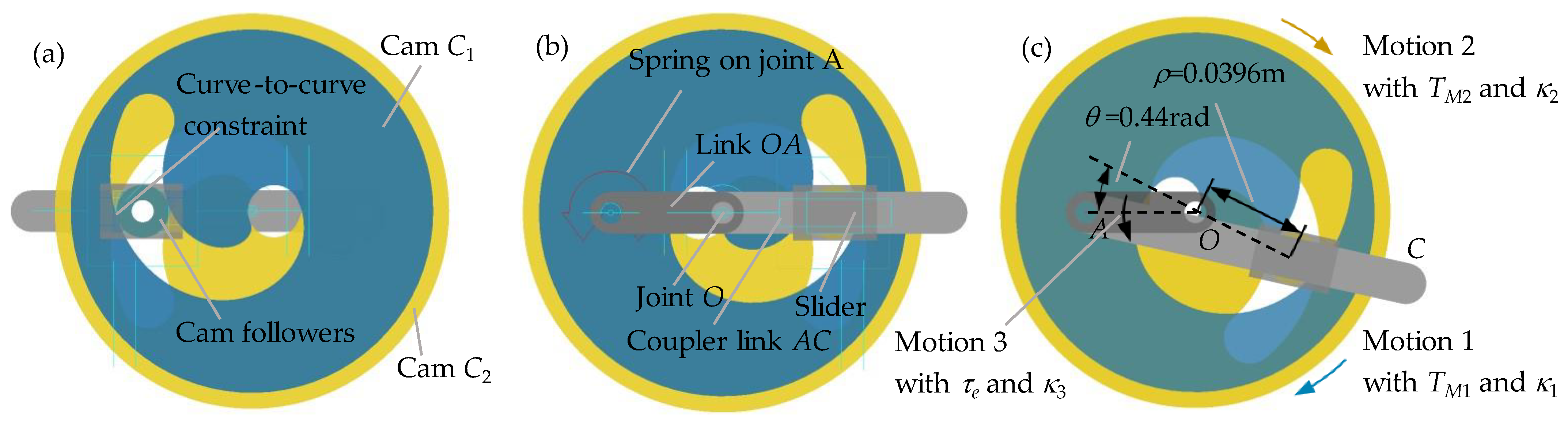
2.1. Problem Description

The existing reconfigurability design of the adjustable stiffness actuator takes the stiffness range as the design optimization objective, and the optimization objective is single, which limits the versatility of the actuator. In a robot system, there are usually many degrees of freedom. For example, the Tesla humanoid robot has 28 degrees of freedom. Improving the versatility of the structural design of the actuator is the key to reducing costs. In fact, in addition to the stiffness adjustment range, the key performance indicators of the adjustable stiffness actuator also include output torque, stiffness adjustment time, and stiffness adjustment accuracy. At present, limited by the structural design, there is no model that can cover all the above key performance indicators, and it is impossible to carry out multi-objective design optimization under a unified mathematical model, and the versatile design of the actuator is limited.

2.2. Reconfiguration Method of the Cam-Based VSA for High Versatility

In this paper, a pitch curve synthetic approach for VSA reconfiguration design with the following advantages is provided as follows:
(1) Cam-based VSA with a common driven node. The radial position of the common node can be changed for stiffness adjustment by cam differential motion and its tangential position can be changed for output position control by cam synchronized movement. The cam groove can resolve the driven force into two orthogonal directions: one for stiffness adjustment and another for position balance. Obviously, this common node makes the stiffness adjustment time, accuracy and output torque of the actuator have common structural constraints. Therefore, the system model established in this paper can cover the above key performance indicators.
(2) Feasible solution space of pressure angle, considering the mechanical constraint of the variable stiffness module. The solution space is decided by two solution boundaries: the upper one generated by the stiffness adjustment force and the lower one by the position balance force. The cam can be shaped in a polar coordinate system with the pressure angle function, based on the approximation functions of the two boundaries.
(3) Synthetic approach of pitch curve for reconfiguration design. The paper establishes analytic relationships among the cam pressure angle, stiffness adjustment speed and accuracy, and load distribution. Three cam configurations with different characteristics are given: a bigger pressure angle is helpful to improve the stiffness adjustment speed; a smaller one is beneficial to obtain a more even load on the dual motors; a tradeoff between the above two cases can result in a uniform stiffness adjustment accuracy. By an internal adjustment of the cam groove shape, the VSA can be arbitrarily reconfigured depending on its functionality with the external interface unchanged. This greatly increases the versatility of the actuator design.
The principle of the proposed VSA is illustrated in Figure 1. It is mainly composed of a stiffness adjustment module (VSM) and the cooperative cam-based driving module. In the VSM, the coupler AC and the output link OA are connected by a spring, as shown in Figure 1. Then the rigid guide rod mechanism is transformed into a compliant mechanism. In this mechanism, the spring’s torsion angle is just the transmission angle between AC and OA (α in Figure 1). The difference between the input link OB and the output link OA is defined as the deformation angle of the VSA (θ in Figure 1).
τe is the load exerted on the output link of the VSA, and can be obtained as
τ e = τ s ( α ) d α d θ
where τs(α) is the elastic torque of the spring with respect to deflection α. Thus, the output stiffness K can be
K = d τ e d θ = k s ( d α d θ ) 2 + τ s ( α ) d 2 α d 2 θ
where ks is the spring stiffness. / indicates the deformation transmission ratio and can be expressed as
d α / d θ = ρ cos ( θ α ) / ( a cos α + ρ cos ( θ α ) )
where a and ρ are the length of link OA and link OB. By changing ρ, / can be regulated, and so the stiffness K.
The VSM is driven by two motors through two symmetrical cams (cams C1, C2 in Figure 1). Joint B is arranged at the intersection of the symmetrical cam pitch curve, which can realize the adjustment of position and stiffness at the same time. To reduce the internal friction, joint B is composed of two bearing for the two cams, called cam followers. As well, they are placed in the cams’ common groove. The stiffness K can be changed with a tunable node B implemented by cams’ differential rotation. The speed and accuracy of the stiffness adjustment are decided by the shape of the cam. Furthermore, there is: τe = TM1 + TM2. At the same time, the cam acts as a force resolver for stiffness adjustment and position balance, and decides the load distribution feature (the ratio of TM1/TM2). The output power of the VSA can be enhanced with optimal load distribution.
So, VSA with different characteristics can be obtained by reconfiguring the cam pitch curve. As well, the cam shape reconfiguration is closely related to the stiffness adjustment module, whose specifications are defined in the previous research work [34].

3. The Cam Pitch Curve Synthetic Approach for Reconfiguration Design

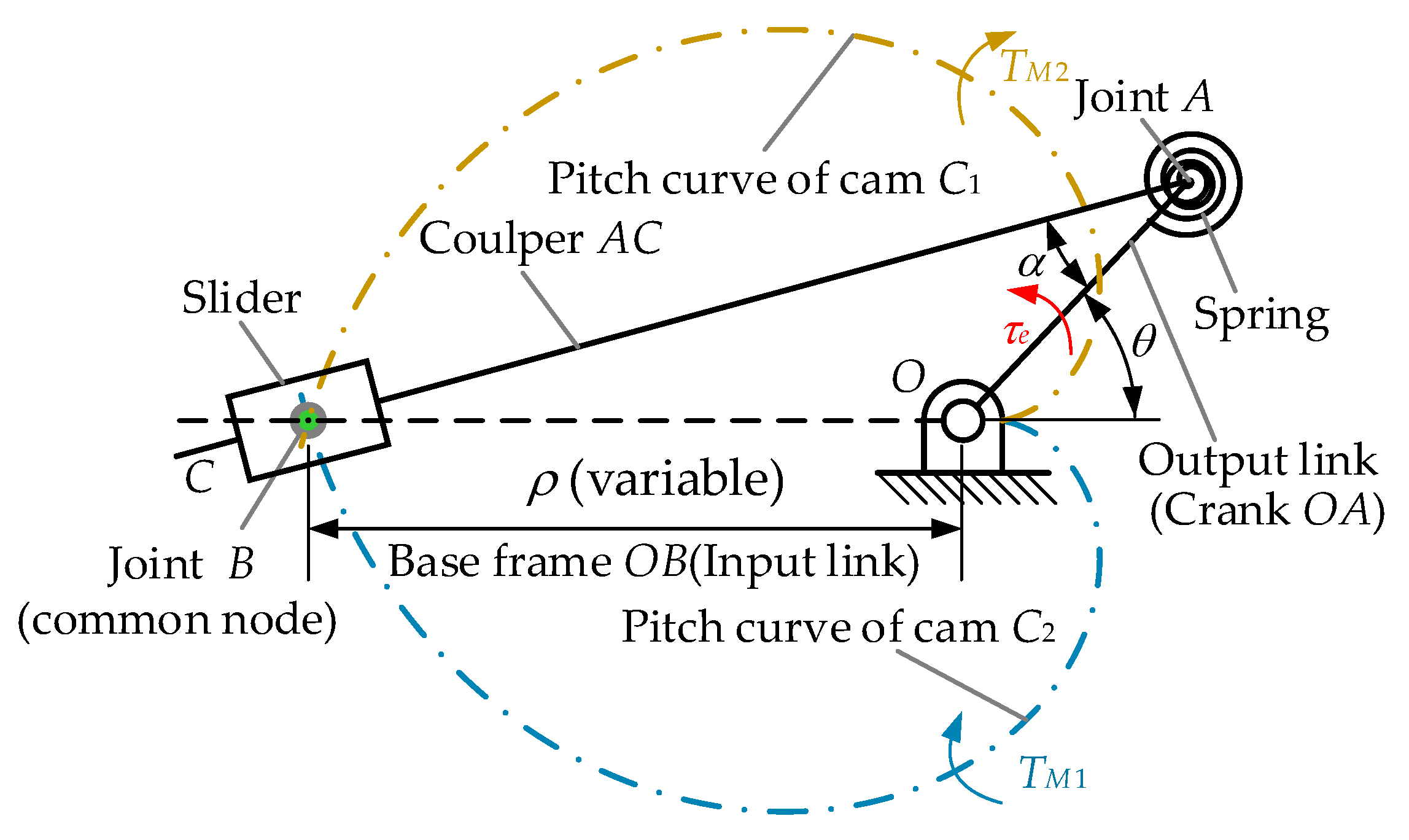
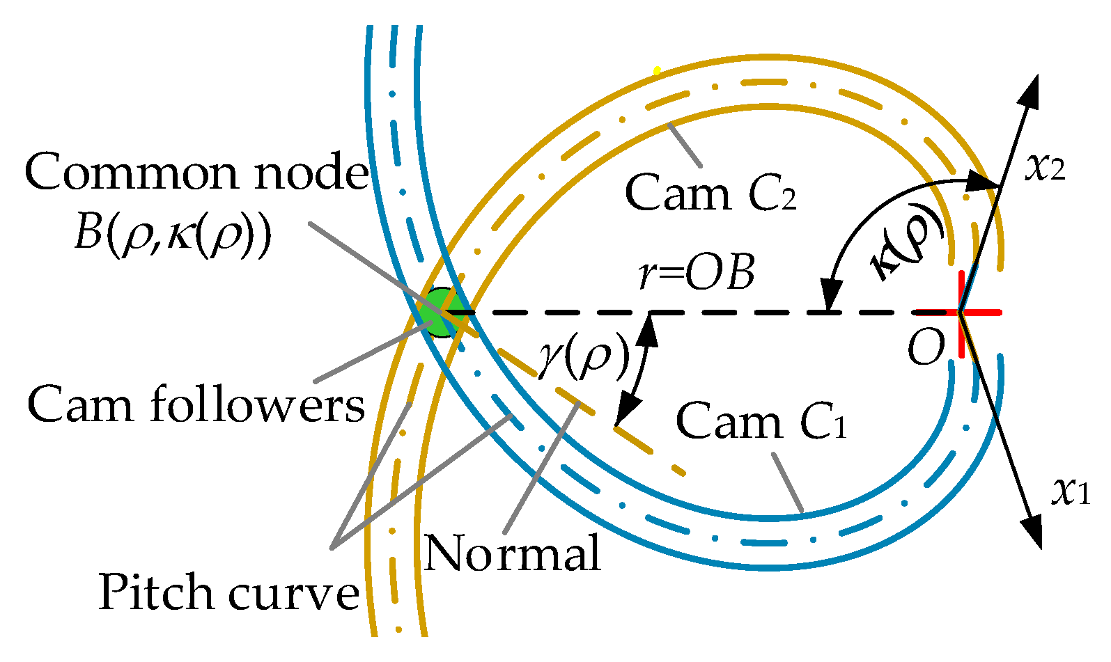
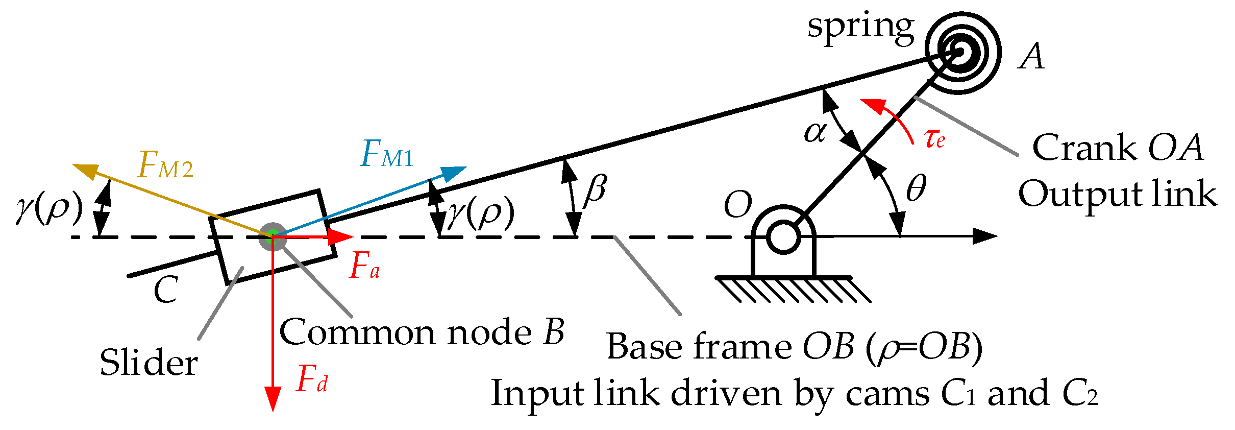
3.1. Cam Pitch Curve Modeling

In this paper, the cam pitch curves are described in a polar coordinate system (Figure 2). The intersection node B is represented by polar coordinate B(ρ,κ(ρ)). ρ is the radial distance corresponding to certain stiffness (ρ = OB) and κ(ρ) is the angle mapped to ρ in the polar coordinate system. On node B, the stiffness adjustment pressure angle is defined as the cam curve pressure angle. (γ(ρ) in Figure 2). In the part polar coordinate systems, γ(ρ) is the key for cam reconfiguration design. It establishes direct mathematical relationships among cam shape, the feasible solution space of cam reconfiguration, and the VSA’s primary characteristics.
The pitch curve can be shaped by the relationship among ρ, γ(ρ) and κ(ρ) as
κ ( ρ ) = ρ min ρ [ ρ tan ( γ ( ρ ) ) ] 1 d ρ
where ρmin is the minimal length of link OB.

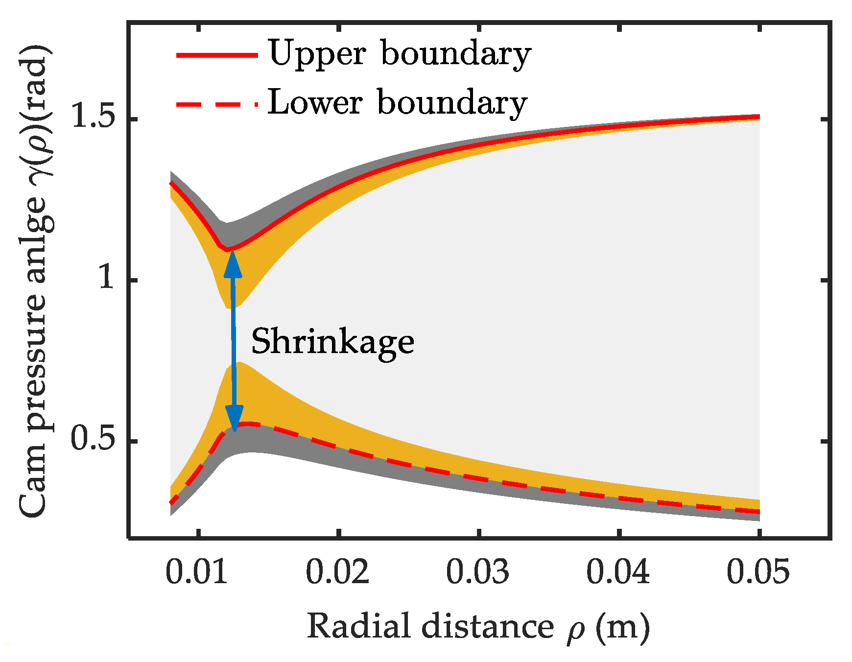
3.2. Feasible Solution Space of Cam Reconfiguration under the Basic Constraints

Benefiting from the symmetry of the structure, only the deformed configuration with a positive direction is discussed. Corresponding to Figure 1 and Figure 2, the balanced forces on node B are shown in Figure 3.
The force on the followers is resolved into two orthogonal directions (Fd, Fa, red highlight in Figure 3). Fd is called the counter-force for position control and Fa is called the counter-force for stiffness adjustment. The ratio of Fa over Fd can be expressed as
F a / F d = tan β = a sin θ / ( ρ + a cos θ )
where β indicates the angular displacement of the slider relative to OB.
FM1, FM2 are the normal force exerted on the common node by cams C1 and C2, and there is
{ ( F M 1 + F M 2 ) sin γ ( ρ ) = F d ( F M 2 F M 1 ) cos γ ( ρ ) = F a
Solution space of cam pitch curve. To ensure the bearing followers not be overloaded, γ(ρ) should meet the following constraint equation:
F M 2 = τ e ( 1 + tan β tan γ ( ρ ) ) ρ 1 / 2 sin γ ( ρ ) [ F b ]
Considering the specification constraints in [35], the maximum value of the β, θ, α, τe in Equation (7) is obtained according to Equations (1) and (3), and graphed in Figure 4. Correspondingly, the feasible solution space of γ(ρ) is calculated numerically and shown by the area enclosed by the solid red line and the dashed red line in Figure 5. The dashed red line and solid red line indicate its lower and upper solution boundary respectively. The former represents the allowable minimum γ(ρ) for Fd and the latter represents the allowable maximum γ(ρ) for Fa. Beyond this boundary, the overload problem appears on the bearings.
There appears a local shrinkage phenomenon near ρ = 0.014 m on the solution space. This is caused by the change of the main factors determining γ(ρ). When (ρ < 0.014 m), a small γ(ρ) is allowed with low stiffness. Afterward, the stiffness increases quickly and leads to a sharp increase of γ(ρ). After the shrinkage point, the decreasing ρ−1 and β become the dominant factors and the γ(ρ) decreases slowly. The upper boundary curve exhibits an antisymmetric feature as the second solution for Equation (7). The two together generate the shrinkage phenomenon. The degree of the shrinkage is decided by the bearing’s rated load. The feasible solution space would broaden outward slightly with a larger bearing ([Fb] = 950 N), indicated by the grey area in Figure 5. But it would shrink inward seriously with a smaller bearing ([Fb] = 750 N), as indicated by the yellow area in Figure 5. The difference is caused by the nonlinearity of the FM1 over γ(ρ) in Equation (6). This trend is more significant near shrinkage point as the β in this interval is larger, as shown in Figure 4. So, a favorable choice of the cam follower bearing should be based on the mechanical property of the variable stiffness module. Bearing a too small rated load would limit the solution space for the cam reconstruction design and too large one does not help much but increases the curvature radius.
Pressure angle constrained by undercutting. The minimum curvature radius should be large than the radius of the cam followers. So, any feasible γ(ρ) in Figure 5 should meet the following undercutting constrained equation:
ρ pitch = ρ [ 1 + tan 2 γ ( ρ ) ] 3 / 2 | tan 2 γ ρ γ ( ρ ) tan γ ( ρ ) sec 2 γ ( ρ ) + 1 | D / 2
where D indicates the diameter of the cam followers, γ’(ρ) is the derivative of γ(ρ) over ρ.
Expression of the feasible pressure curve in the solution space. The upper solution boundary can be approximately approached by the superposition of the following two pressure angle functions: the main function γfit(ρ) in Equation (9) and the correction function γc(ρ) in Equation (10). γfit(ρ) devotes to fitting the pressure angle data after the shrinkage point in Figure 5 (ρ = 0.014 m), and γc(ρ) to compensate for its value in the range before the shrinkage point.
γ f i t ( ρ ) = 144101 ρ 4 + 28797 ρ 3 2183 ρ 2 + 77 . 1 ρ + 0 . 412
γ c ( ρ ) = a c + b c ( ρ min / ρ ) n c
Setting ac = −0.015, bc = 0.4, nc = 6 by enumeration method, the upper solution boundary function can be expressed as
γ up ( ρ ) = γ f i t ( ρ ) + γ c ( ρ )
In a likewise fashion, the lower solution boundary function can be approximately approached by
γ low ( ρ ) = 20830 ρ 4 5303 ρ 3 + 531.5 ρ 2 27.36 ρ + 0.864 0.25 ( ρ min / ρ ) 5
Then the pressure angle curve in the solution space can be generally expressed as
{ γ ( ρ ) = W ( ρ ) γ up ( ρ ) + ( 1 W ( ρ ) ) γ low ρ pitch D / 2
where W(ρ) is the function to be determined, and there is 0 ≤ W(ρ) ≤ 1.

3.3. Cam Reconfiguration Synthetic Based on Different Performance Index of the Variable Stiffness Actuator

Case 1: cam synthetic based on stiffness adjustment speed, such as actuator for wrist joint in a humanoid robot. Usually, it needs to be used for some fine actions, such as grabbing, polishing, and grinding. With a given motor speed, the stiffness adjustment speed can be proportional to angle κ(ρ) in Equation (4) and inversely proportional to γ(ρ). So, a shorter stiffness adjustment time can be obtained with the pressure angle curve moving toward the upper boundary curve in Figure 5, i.e., W(ρ) → 1.
Case 2: cam synthetic based on output stiffness accuracy, such as actuator for wrist joint in a humanoid robot. Usually, it needs to be used for some fine actions, such as grabbing, polishing, and grinding. A smaller value of the stiffness adjustment resolution is beneficial to obtain a high output stiffness accuracy and is defined as:
a ρ = Δ p K κ = Δ p K ρ ρ κ = Δ p K ρ ρ tan ( γ ( ρ ) )
where Δp indicates the position resolution of the cam, i.e., the resolution of the polar angle κ. ∂K/∂κ is the partial derivative of K over κ and represents the stiffness resolution related to κ.
To simplify the solution, we ignore the nonlinearity of output stiffness in Equation (2). Then ∂K/∂ρ can be simplified as
K ρ = 2 a ρ ( a + ρ ) 3
For the case with a higher priority of stiffness accuracy, we can predefine the stiffness adjustment function by
S ( ρ ) = K ρ ρ tan ( γ ( ρ ) )
Then the relationship between W(ρ) and S(ρ) can be mapped as
S ( ρ ) = K ρ ρ tan ( W ( ρ ) γ up ( ρ ) + ( 1 W ( ρ ) ) γ low )
The local stiffness adjustment accuracy can be arbitrarily set according to the requirements of different tasks by pre-definition of W(ρ). For a certain ρ range with higher stiffness adjustment accuracy, the corresponding S(ρ) can be adjusted to a lower value with a small W(ρ). The cam pressure angle function based on the predefined stiffness adjustment accuracy can be decided by
κ ( ρ ) = ρ min ρ 1 S ( ρ ) K / ρ d ρ
Case 3: cam synthetic based on load distribution on its dual motors, such as actuator for waist joint in the legged robot. It requires the actuator to have a large driving capacity, but it does not require a high stiffness adjustment time. The torques TM1 and TM2 on the cams C1 and C2 can be derived from FM1 and FM2 as
{ T M 1 = F M 1 sin γ ( ρ ) ρ = τ e ( 1 + tan β ) tan γ ( ρ ) ) / 2 T M 2 = F M 2 sin γ ( ρ ) ρ = τ e ( 1 tan β tan γ ( ρ ) ) / 2
In this paper, we use ϕ to evaluate the load distribution. It is defined as the smaller torque on the cams over its bigger one. When θ > 0, there is TM 1 < TM 2. Then ϕ can be
ϕ = T M 1 T M 2 = 1 tan β tan γ ( ρ ) 1 + tan β tan γ ( ρ )
When θ < 0, the ϕ can be re-expressed as is
ϕ = T M 2 T M 1 = 1 tan β tan γ ( ρ ) 1 + tan β tan γ ( ρ )
Four different reconfiguration cases can be discussed. First, ϕ = 1. The motors share the external load evenly. In this case, a serious overload phenomenon happens and the stiffness cannot be tuned. Second, 0 < ϕ <1. The dual motors synergistically drive an external load. The proximity of the amount is dependent on the γ(ρ). The smaller the value of γ(ρ), the more uniform the load distribution. Third, ϕ = 0. Only a single motor takes the load. This is the load distribution status of the existing freestanding VSA. Fourth, ϕ < 0. The motors work against each other. This reflects the load distribution state of the existing antagonistic VSA.
According to the above discussion, a simple conclusion can be made: for case 1, a bigger γ(ρ) is helpful to improve the stiffness adjustment speed; contrary to case 1, a smaller γ(ρ) is better to obtain a more even load on the two motors in case 3; case 2 is between the case 1 and case 3.

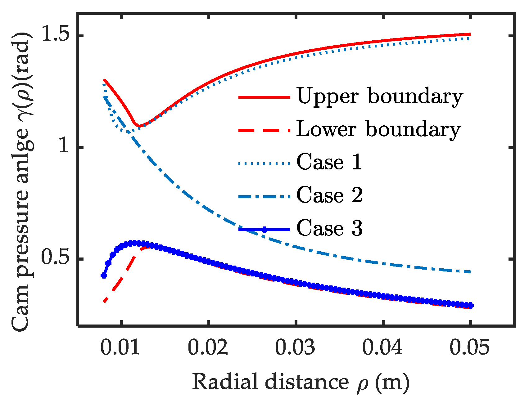
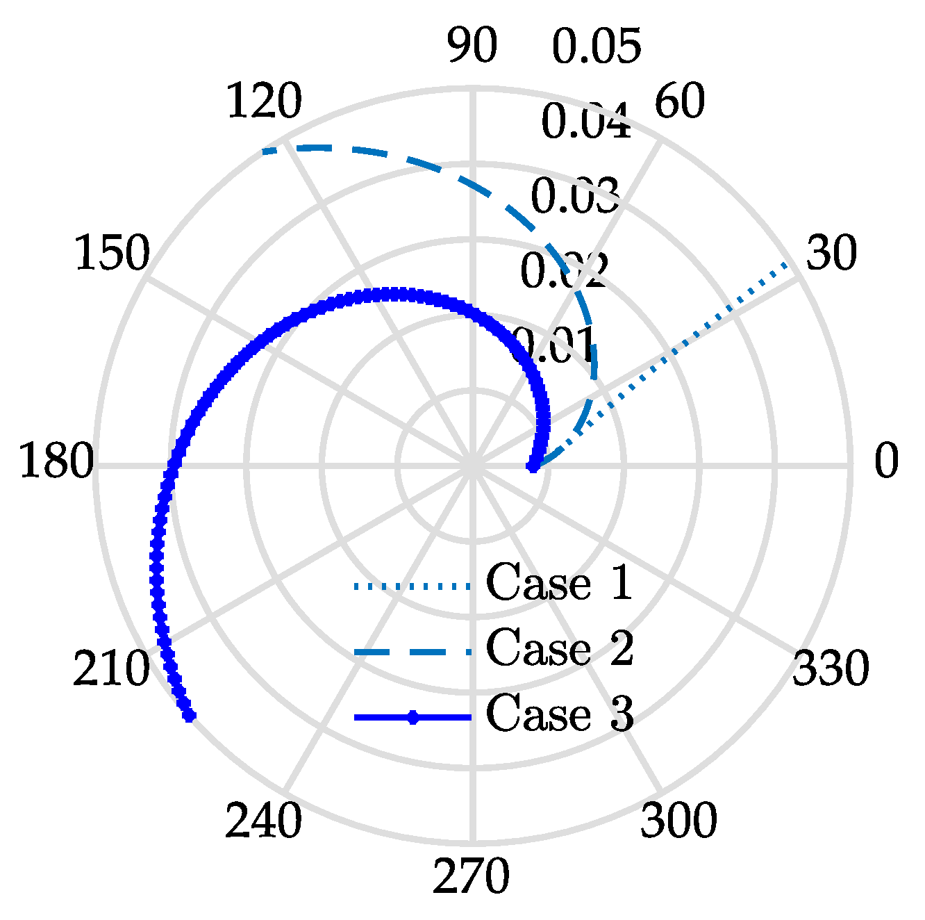
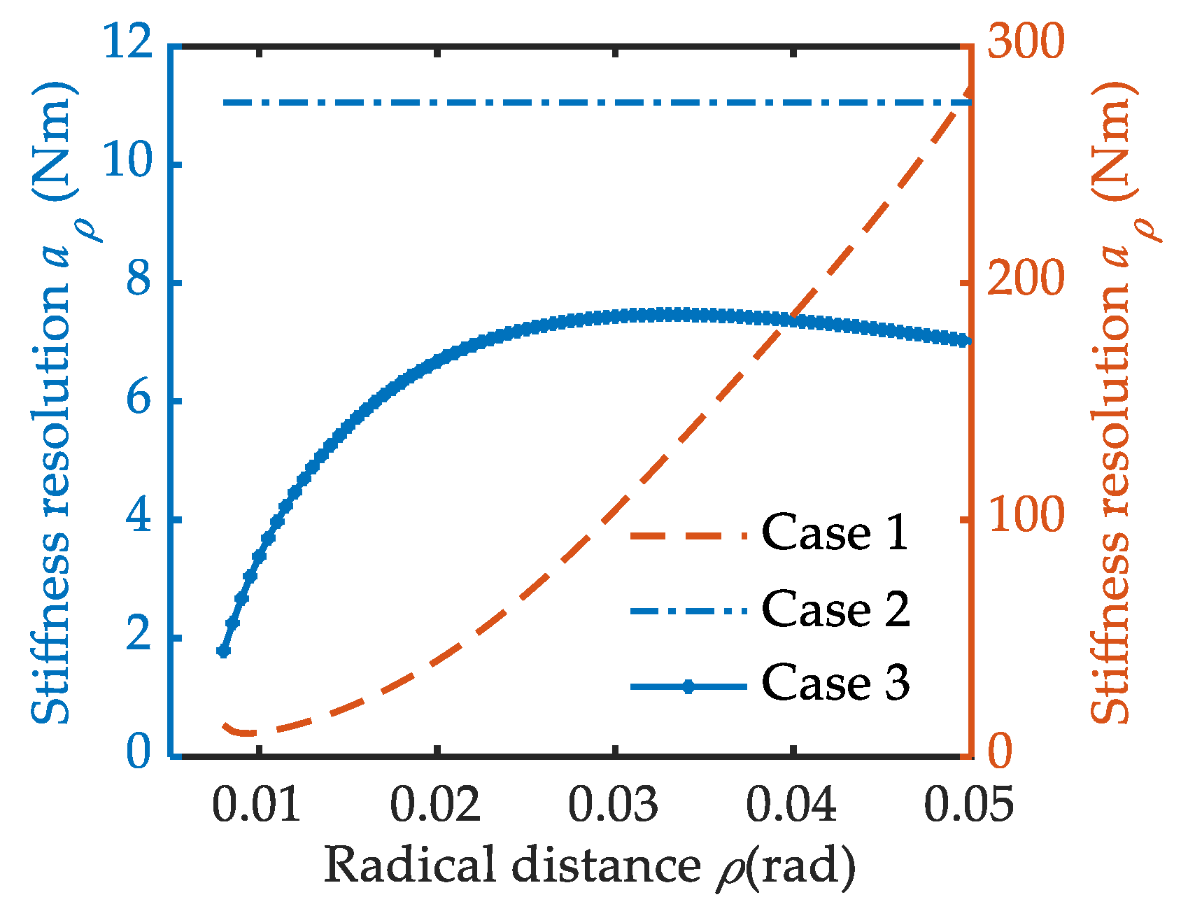
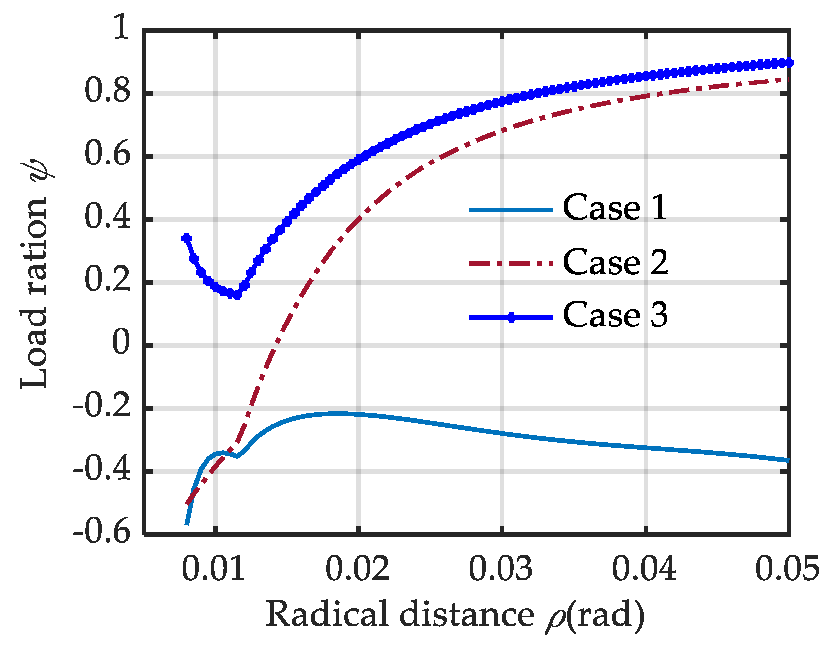
3.4. Three Cam Reconfiguration Results Based on Three Special Cases

Three special cam reconfigurations based on the above three cases are given and compared in this section. For case 1, the VSA can obtain its maximum stiffness adjustment speed with W(ρ) = 1. In this case, the stroke of the polar angle for stiffness adjustment is κ = 0.57 rad. The pressure angle curve approaches its upper solution boundary (point line in Figure 6). Going back to Equation (4) with Equation (13), the pitch curve for case 1 can be shaped. It is very close to straight line (point line in Figure 7). Obviously, this is more suitable for scenes with requirements for high stiffness adjustment speed. We should note that it does not cover the stiffness adjustment accuracy, as the stiffness resolution is extremely uneven in the whole ρ range. To simplify the comparison, we assume Δp = 1 rad in Equation (14). With a small ρ value, the adjustment resolution would be very slow and dramatically increase from 10 Nm to 283 Nm with an increasing ρ (solid Figure 8). This is not conducive to improving the accuracy of stiffness adjustment. Another disadvantage is that the VSA works in antagonistic mode with ϕ < –0.2 (point line in Figure 9). The two driving motors consume each other seriously.
For case 3, an optimal load distribution is obtained with W(ρ) = 0. In this case, the pressure angle curve approaches its low solution boundary (asterisk marked in Figure 7). There is ϕ >0.6 with ρ > 0.02 m. And ϕ would be over 0.8 when ρ > 0.032 m (asterisk marked in Figure 8). It is very useful in full exploitation of the output power of the dual driving motors. Its shape is like that of an Archimedean spiral, but with a variable-pitch (asterisk marked in Figure 6). Obviously, it comes at the cost of stiffness adjustment speed, with a polar angle stroke of κ = 3.86 rad. Trade off can be made between the stiffness adjustment time and the output power (or load distribution). It can be realized by moving the pressure angle curve toward the upper boundary curve with a larger W(ρ). In this way, the output power would decay but the stiffness adjustment speed would be higher.
A special case for case 2 is that: S(ρ) = C. C is a constant related to stiffness adjustment accuracy aρ. Going back to Equation (18) with Equations (15) and (16), the pressure angle with a uniform stiffness adjustment accuracy can be expressed as
γ ( ρ ) = arctan ( 0.5 C a 1 ρ 2 ( a + ρ ) 3 )
By setting C = 0.13, the pressure angle S(ρ) can go through the shrinkage area smoothly (dashed line in Figure 7) and the stiffness resolution remains the same in the whole κ range (dotted line in Figure 9), i.e., aρ = 11 Nm. Its value is slightly bigger than that of case 3, for the pressure angle is beyond that of case 3 (dotted line in Figure 7). Except for the uniform stiffness adjustment accuracy, it is also a good embodiment of tradeoff design between the stiffness adjustment time and the output power (or load distribution). The pressure angle curve of case 2 is close to that of case 1 in the low ρ range (W(ρ) → 1 when ρ < 0.014 m) and exhibits a stable offset to that of case 3 in the high ρ range (W(ρ)→0 when ρ > 0.02 m). It results in a pitch curve between case 1 and case 3 (dashed line in Figure 6). A higher stiffness adjustment speed with a stroke polar angle of κ = 2.16 rad is obtained. At the same time, the load ratio also reaches 0.6 quickly with an increasing ρ. There is good compatibility for stiffness adjustment time and the output power and stiffness adjustment accuracy. The difference and relationships of the three cases are summarized in Table 1.

4. Experiment Verification and Analysis of the Optimal Load Design

The cam shape in case 3 is chosen for the VSA’s output power enhancement in a compact joint of the support fund. It focuses on the load distribution design. The load ratio is verified by the Adams simulation and physical prototype experiment from different aspects.

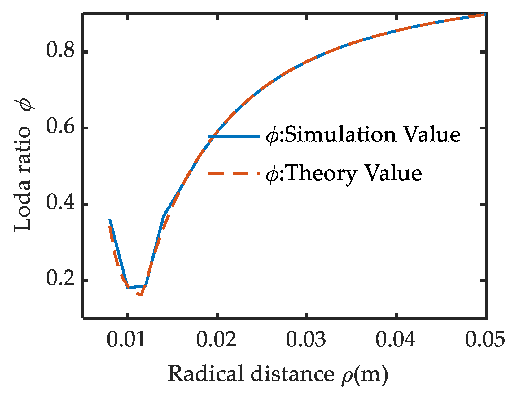
4.1. Load Distribuation Erification by Adams Simulation

Adam’s simulation settings. Adam’s simulation can provide a fast and exact verification of the design result when the virtual prototype is very close to the theory prototype. It can be regarded as an important supplement to the physical prototype experiment. In cam modeling, the system friction was neglected in the static equilibrium equations of Equations (5) and (19). To avoid the influence of inertia force and friction on the simulation results of cam load ratio, the virtual prototype with non-friction, zero-damping is established, as shown in Figure 10, according to the working principle proposed in Figure 1. The model has the same specifications with that proposed in [34].
Figure 10a is the bottom view of the virtual prototype. The cam followers are placed in the common grooves of the dual cams with curve-to-curve constraints. Figure 10b is the front view. The cam followers are connected to the linkage mechanism via a slider. Cams C1 and C2 rotary around the center O with motion 1 and motion 2. Their angle displacements are indicated by κ1 and κ2 respectively. Then the polar angle can be indicated by κ = (κ1κ2)/2 and the corresponding ρ can be obtained by Equations (3) and (12). The output link OA moves around the center O with motion 3 with angular displacement of κ3. To simplify the simulation, the κ3 is set to zero. Then the deflection angle of the variable stiffness module can be expressed as θ = (κ1 + κ2)/2.
The simulation steps are as follows:
(1)
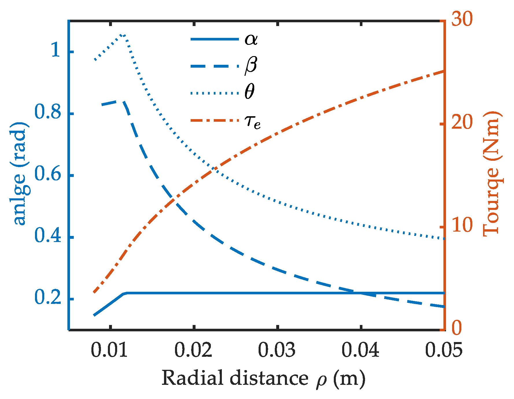
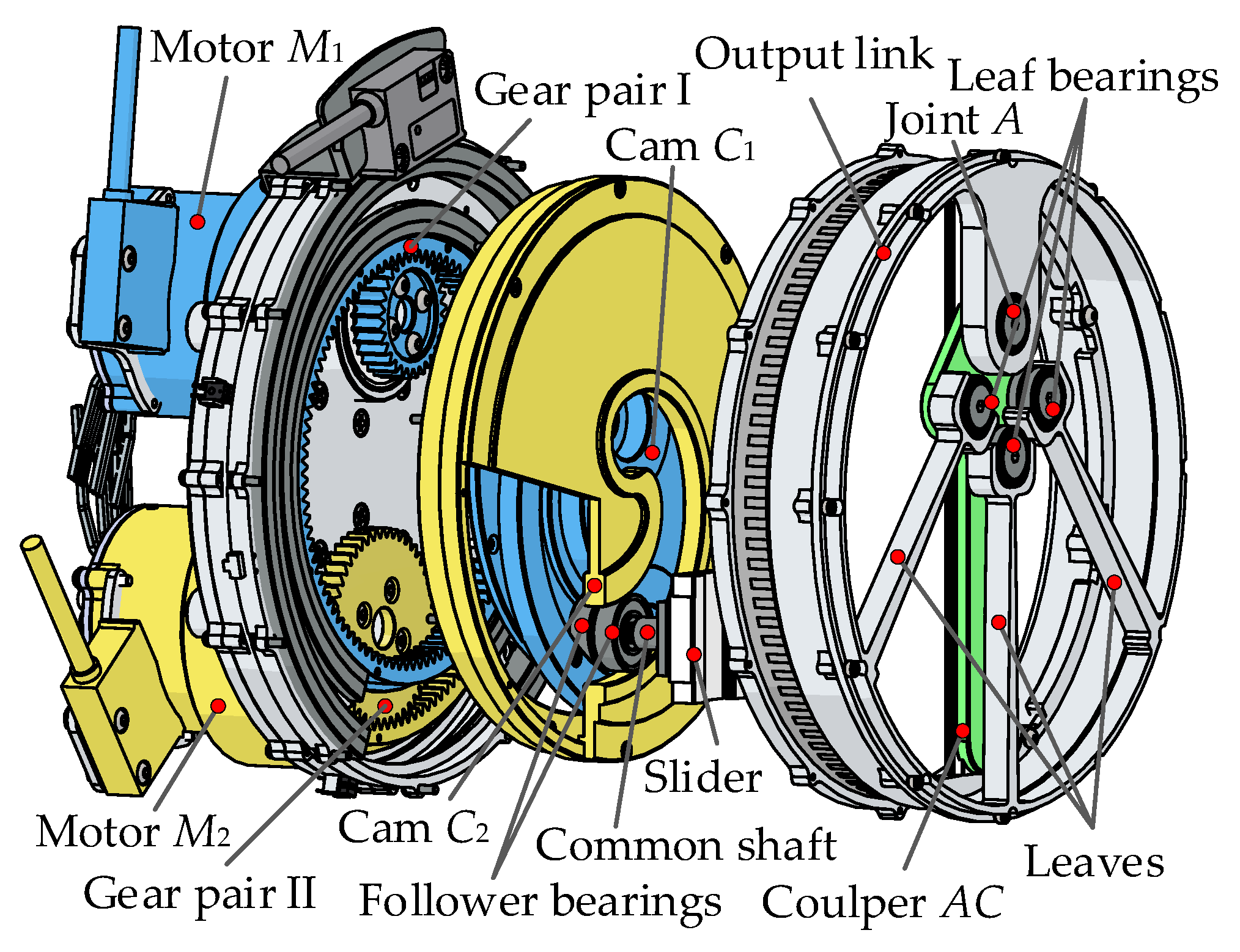
First, adjust the value of ρ with no deformation by the reverse motion of cams C1 and C2. The measurement range varies from ρ = 0.008 m to ρ = 0.05 m, with a step of 0.002 m. The motion angle κ1 and κ2 of cams C1 and C2 are decided by
{ κ 1 ( ρ ) = κ 2 ( ρ ) = κ ( ρ ) = ρ min ρ [ ρ tan ( γ ( ρ ) ) ] 1 d ρ γ ( ρ ) = 20830 ρ 4 5303 ρ 3 + 531.5 ρ 2 27.36 ρ + 0.864 0.25 ( ρ min / ρ ) 5
A simple example is demoed in Figure 10b, with κ1= − κ2 = 3.14 rad, ρ = 0.0396 m, θ = 0 rad.
(2)
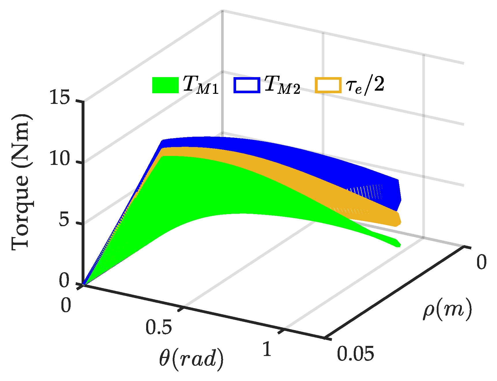
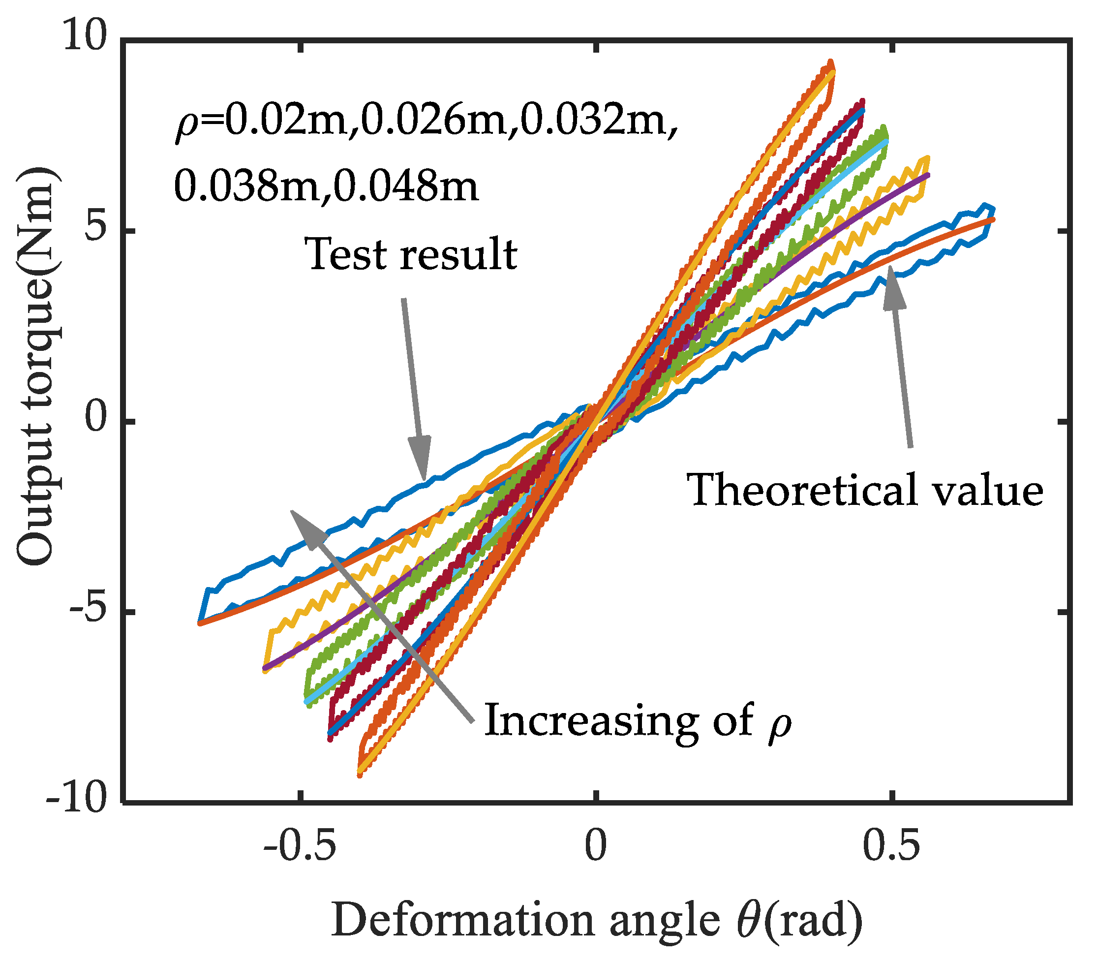
Secondly, deform the variable stiffness module with an angle θ by synchronized motion. The maximum θ corresponding to each ρ is shown in Figure 4. It is mainly constrained by the allowable spring angle. Now the motion angle exerted on the cams C1 and C2 become
{ κ 1 ( ρ ) = ρ min ρ [ ρ tan ( γ ( ρ ) ) ] 1 d ρ + θ κ 2 ( ρ ) = ρ min ρ [ ρ tan ( γ ( ρ ) ) ] 1 d ρ + θ
A deformed configuration with κ1 = 3.58 rad, κ2 = −2.7 rad, ρ = 0.0396 m, θ = 0.44 rad is exhibited in Figure 10c.
Adams simulation results. The driving torque TM1 and TM2 exerted on the two cams can be observed as a characteristic of motion 1 and motion 2 in ADAMS. And the output torque τe can be obtained from motion 3. For a clear illustration, τe is scaled down by 0.5 times. TM1 is indicated by the green mesh, TM2 the blue mesh and τe/2 the yellow mesh, as shown in Figure 11. There is always 0 < TM1 < τe/2/ < TM2 and TM1 + TM2= τe, i.e., the VSA works with helping mode in the whole working space. The difference between TM1 and TM2 decreases notably with an increasing ρ, but increases with an increasing deflection angle θ. For quantitative analysis, the load ratio with maximum θ is graphed in Figure 12 (ϕADMAS, solid line).
There is a tiny difference between ϕADMAS and ϕtheory near ρ = 0.014 m. It is caused by the simulation step. For the theory value of load ratio in Equation (20) (ϕtheory), the calculation step is 0.0005 m. And for the ϕADMAS, the step is 0.002 m. The influence appears when the ρ-ϕ curve changes sharply in the range of ρ < 0.016 m. But its impact becomes very weak in the range of ρ > 0.016 m, as the ρ-ϕ curve is gentle in this area. So, we can conclude that the correctness of the cam design method is proved effectively by the load ratio observation in ADAMS. We can conclude that simulation experiments fully verified the correctness of the load distribution design during the deformation process.

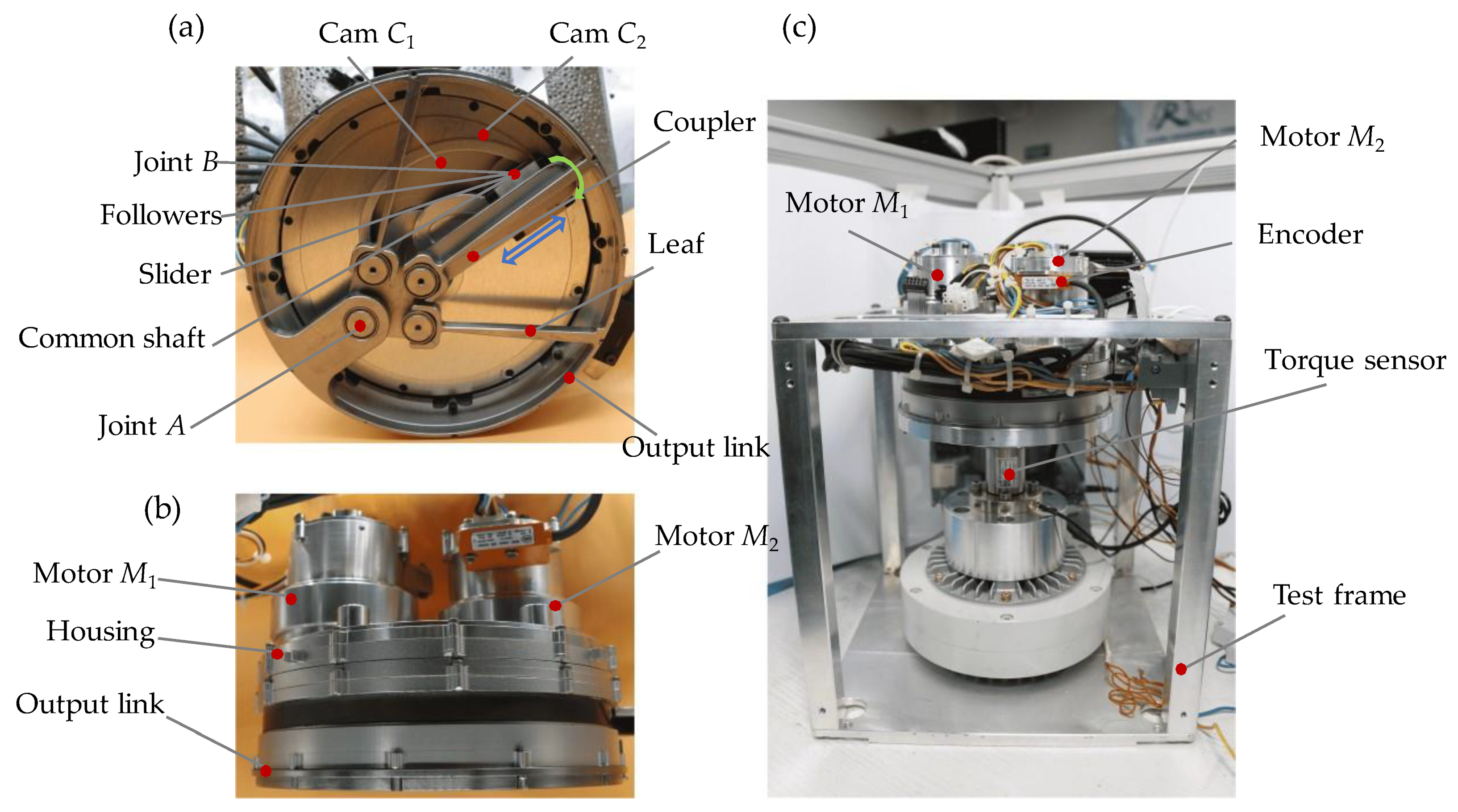
4.2. Performance Validation by Physical Prototype

CAD model of a physical prototype. The CAD model is illustrated in Figure 13. The motor M1 determines the cam C1 position, and the reduction ratio between the two is 100:29. The motor M2 devotes to the cam C2 position and the reduction ratio is 130:47. The cam follower consists of two bearings, the outer rings are respectively arranged in the two cam grooves, and the inner ones are mounted on a common shaft, which is bolted with a slider on guide rod AC. Through the differential movement of the cams, the slider can slide along the guide rod AC to change the radial position and realize the stiffness adjustment. To ensure the compactness of the actuator, the torsion spring at point A is derived from the stiffness adjustment module [35].
Physical prototype of reconfigurable cams. The symmetrical cams C1 and C2 in Figure 14a,b was machined with the same pitch curve in Figure 10. It focuses on optimal load distribution for output torque enhancement of the VSA. By changing the cam groove shape, the performance of the VSA can be reconfigured, as described in case 1 and case 2.
Physical prototype and experiment platform. After the cam group is installed coaxially, a common cam groove is formed. Joint B is set at the common groove through a common shaft (Figure 15a) and its position is decided by the cams’ position. By cams differential control, the goal ρ for stiffness adjustment can be set and the stiffness of the VSA would be changed. By cams’ synchronous motion, the deformation angle θ changed. To simplify the measurement, both the housing and the output link (Figure 15b) are bolted with the test frame (Figure 15c) Then the ρ and θ can be obtained after reduction ratio calculation with the encoder value of the dual motors. The output torque can be measured through the internal torque sensor between them.
According to the previous research results [35], the actual stiffness of the manufactured torsion spring is 85 Nm/rad. To avoid overloading the stiffness adjustment module, a matching design of the drive motors is carried out, combined with the load distribution design result in Figure 12. The torque constant of motor M1 is 36.9 mN/A and that of motor M2 is 25.1 mN/A. Considering 40% transfer efficiency, the rated driving torque that the motor M1 can provide to the cam C1 is 6.12 Nm and the rated torque that M2 provides to cam C2 is 6.06 Nm.
Physical prototype performance results. Using a method similar to the ADAMS simulation, the ρ of the VSA is tuned to a certain value by cam differential movement, such as ρ = 0.02 m, ρ = 0.026 m, ρ = 0.032 m, ρ = 0.038 m, ρ = 0.048 m. Then the cams are synchronously driven, and the ρ will remain unchanged in the deformation progress, i.e., the output stiffness remains constant. The force-deformation characteristics of the prototype under different ρ values are shown in Figure 16.
In the direction of the arrow in Figure 16, the output stiffness is respectively 9.4 Nm/rad, 13.19 Nm/rad, 16.89 Nm/rad, 20.17 Nm/rad and 25.28 Nm/rad. For each ρ value, there are two kinds of curves, the loop curve is the actual test result of the output torque, which corresponds to the VSA loading loop; the other curve is the theoretical curve of the force-deformation relationship, which is calibrated according to the force-deformation Equation in (1). The two curves are highly convergent during loading and diverge during unloading. This is mainly due to the elastic hysteresis during unloading, and the elastic hysteresis amplitude is 0.5 Nm. The performance parameters of the prototype are shown in Table 2.
In the direction of the arrow, the value of ρ increases from 0.02 m to 0.048 m. Correspondingly, the deformation is 0.593 rad, 0.523 rad, 0.457 rad and 0.471 rad and the maximum output torque is 5.58 Nm, 6.91 Nm, 7.73 Nm, 8.42 Nm, 9.5 Nm. The changing trend of the maximum output torque corresponds to the load distribution characteristics in Figure 12. When the ρ value is close to 0.048 m, the load ratio is close to 0.82. According to the load distribution Equation in (19), the theoretical maximum output torque is 11 Nm when ρ = 0.048 m. The measured maximum output torque is 9.5 Nm. The two are relatively close. The discrepancy between the test results and the theoretical results stems from the fact that the adjustable stiffness module has reached the deformation capacity allowed by its design. It shows that through the optimal design of the load distribution, the torque output performance of the dual motors can be fully utilized, and the output torque of the adjustable stiffness actuator can be enhanced. This verifies the correctness of the load distribution from the aspect of output torque enhancement.
From the obtained results, we can conclude that the proposed VSA interacts with the outside world through the spring and the contact stiffness can be changed from 2.51 Nm/rad to 26.23 Nm/rad. And the deformability verifies from 1.785~0.38 rad correspondingly. This is similar to an artificial muscle, which can be made very soft (2.51 Nm/rad) or very stiff (26.23 Nm/rad), with mechanically controllable flexibility. In a traditional rigid motor, a small contact deformation behavior will generate a huge contact force, which is likely to cause irreversible damage to the person or object in contact with it. However, when VSA performs human-computer interaction, the contact force does not change significantly with the slight change of contact deformation (for example, when the stiffness is 2.51 Nm/rad, the deformation angle changes by 0.1 rad, and the contact force changes only by 0.25 Nm). Besides, it provides enough time for the actuator to respond safely. So, the VSA can improve the safe performance in human-robot interaction.

5. Conclusions

The variable stiffness actuator (VSA) proposed in this paper mainly includes a variable stiffness module and a cam-based actuation module based on two symmetrically arranged cams. The two modules are connected by a common node. And the stiffness is changed by the node’s radical distance adjustment. Moreover, the dual cams resolve the contact force into two orthogonal directions, one for stiffness adjustment and another for position balance. By cam reconfiguration, the VSA with different characteristics can be obtained.
A cam shape synthetic approach for VSA reconfiguration has been put forward. The mathematical formulas are established among the VSA’s key performance indexes and the key design parameter of the driven cam. It covers the following key factors with a mathematical model for multi-objective optimization, including load distribution, stiffness adjustment speed and accuracy. A bigger pressure angle is helpful to improve the stiffness adjustment speed; a smaller one is better to obtain a favorable load distribution on the dual motors for output power enhancement; the case between the above two can realize a uniform stiffness adjustment accuracy. By reconfiguration of the cam pitch curve, the VSA can be reconfigured depending on its functionality with the external interface unchanged.
Furtherly, the VSA prototype with a favorable load distribution is provided. The design result was verified by the ADAMS simulation and physical prototype experiment effectively. In the ADAMS, the simulation results are highly consistent with the theoretical design results. In the fabricated prototype, the output torque enhancement result verifies the correctness of the load distribution.
At the same time, the proposed new structure also brings challenging problems to the control: the output of the dual motors is cross-coupled, and the load of one motor is a major disturbance term of the dynamic model of the other motor. How to realize the high-precision synchronous control of dual motors under the cross-coupling condition is an important research direction in the future.

Author Contributions

F.M.: conceptualization, methodology, investigation, design, measurement, writing—original draft; S.B.: conceptualization, editing, supervision, funding acquisition review and editing; B.L.: Project administration, Supervision, Writing. All authors have read and agreed to the published version of the manuscript.

Funding

This work was supported by the National Natural Science Foundation of China (Grant No. 52075013) and Fundamental Research Funds for the Central Universities (No. YWF-21-J-913).

Institutional Review Board Statement

The study did not require ethical approval.

Informed Consent Statement

The study did not involve humans.

Data Availability Statement

Not applicable.

Conflicts of Interest

The authors declare no conflict of interest.

References

  1. Hong, C.; Tang, D.; Quan, Q.; Cao, Z.; Deng, Z. A combined series-elastic actuator & parallel-elastic leg no-latch bio-inspired jumping robot. Mech. Mach. Theory 2020, 149, 103814. [Google Scholar]
  2. Liu, L.; Misgeld, B.J.E.; Pomprapa, A.; Leonhardt, S. A Testable Robust Stability Framework for the Variable Impedance Control of 1-DOF Exoskeleton with Variable Stiffness Actuator. IEEE Trans. Control Syst. Technol. 2021, 29, 2728–2737. [Google Scholar] [CrossRef]
  3. Shao, Y.; Zhang, W.; Su, Y.; Ding, X. Design and optimisation of load-adaptive actuator with variable stiffness for compact ankle exoskeleton. Mech. Mach. Theory 2021, 161, 104323. [Google Scholar] [CrossRef]
  4. Moltedo, M.; Cavallo, G.; Baček, T.; Lataire, J.; Vanderborght, B.; Lefeber, D.; Rodriguez-Guerrero, C. Variable stiffness ankle actuator for use in robotic-assisted walking: Control strategy and experimental characterization. Mech. Mach. Theory 2019, 134, 604–624. [Google Scholar] [CrossRef]
  5. Gomez-Vargas, D.; Casas-Bocanegra, D.; Múnera, M.; Roberti, F.; Carelli, R.; Cifuentes, C.A. Variable Stiffness Actuators for Wearable Applications in Gait Rehabilitation. In Interfacing Humans and Robots for Gait Assistance and Rehabilitation; Springer: Cham, Switzerland, 2022; pp. 193–212. [Google Scholar]
  6. Li, Z.; Li, W.; Chen, W.H.; Zhang, J.; Wang, J.; Fang, Z.; Yang, G. Mechatronics design and testing of a cable-driven upper limb rehabilitation exoskeleton with variable stiffness. Rev. Sci. Instrum. 2021, 92, 024101. [Google Scholar] [CrossRef] [PubMed]
  7. Robinson, D.W.; Pratt, J.E.; Paluska, D.J.; Pratt, G.A. Series elastic actuator development for a biomimetic walking robot. In Proceedings of the 1999 IEEE/ASME International Conference on Advanced Intelligent Mechatronics (Cat. No. 99TH8399), Atlanta, GA, USA, 19–23 September 1999; pp. 561–568. [Google Scholar]
  8. de Gaitani, F.H.M.; dos Santos, W.M.; Siqueira, A.A.G. Design and Performance Analysis of a Compact Series Elastic Actuator for Exoskeletons. J. Control Autom. Electr. Syst. 2022, 33, 1012–1021. [Google Scholar] [CrossRef]
  9. Yang, Z.; Li, X.; Xu, J.; Chen, R.; Yang, H. A new low-energy nonlinear variable stiffness actuator for the knee joint. Mech. Based Des. Struct. Mach. 2022, 1–15. [Google Scholar] [CrossRef]
  10. Christie, M.D.; Sun, S.; Ning, D.H.; Du, H.; Zhang, S.W.; Li, W.H. A highly stiffness-adjustable robot leg for enhancing locomotive performance. Mech. Syst. Signal Process. 2019, 126, 458–468. [Google Scholar] [CrossRef]
  11. Beckerle, P.; Stuhlenmiller, F.; Rinderknecht, S. Stiffness Control of Variable Serial Elastic Actuators: Energy Efficiency through Exploitation of Natural Dynamics. Actuators 2017, 6, 28. [Google Scholar] [CrossRef] [Green Version]
  12. Liu, H.; Zhu, D.; Xiao, J. Conceptual design and parameter optimization of a variable stiffness mechanism for producing constant output forces. Mech. Mach. Theory 2020, 154, 104033. [Google Scholar] [CrossRef]
  13. Albu-Schaffer, A.; Eiberger, O.; Grebenstein, M.; Haddadin, S.; Ott, C.; Wimbock, T.; Wolf, S.; Hirzinger, G. Soft robotics. IEEE Robot. Autom. Mag. 2008, 15, 20–30. [Google Scholar] [CrossRef]
  14. Li, Z.; Bai, S.; Madsen, O.; Chen, W.; Zhang, J. Design, modeling, and testing of a compact variable stiffness mechanism for exoskeletons. Mech. Mach. Theory 2020, 151, 103905. [Google Scholar] [CrossRef]
  15. Wolf, S.; Grioli, G.; Eiberger, O.; Friedl, W.; Grebenstein, M.; Höppner, H.; Burdet, E.; Caldwell, D.G.; Carloni, P.; Catalano, M.G.; et al. Variable stiffness actuators: Review on design and components. IEEE/ASME Trans. Mechatron. 2015, 21, 2418–2430. [Google Scholar] [CrossRef]
  16. Lee, J.H.; Wahrmund, C.; Jafari, A. A Novel Mechanically Overdamped Actuator with Adjustable Stiffness (MOD-AwAS) for Safe Interaction and Accurate Positioning. Actuators 2017, 6, 22. [Google Scholar] [CrossRef]
  17. Vanderborght, B.; Albu-Schäffer, A.; Bicchi, A.; Burdet, E.; Caldwell, D.G.; Carloni, R.; Catalano, M.; Eiberger, O.; Friedl, W.; Ganesh, G.; et al. Variable impedance actuators: A review. Robot. Auton. Syst. 2013, 61, 1601–1614. [Google Scholar] [CrossRef] [Green Version]
  18. Li, Z.; Bai, S.; Chen, W.; Zhang, J. Nonlinear Stiffness Analysis of Spring-Loaded Inverted Slider Crank Mechanisms With a Unified Model. J. Mech. Robot. 2019, 12, 031011. [Google Scholar] [CrossRef]
  19. Moore, R.; Schimmels, J.M. Design of a Quadratic, Antagonistic, Cable-Driven, Variable Stiffness Actuator. J. Mech. Robot. 2021, 13, 031001. [Google Scholar] [CrossRef]
  20. Li, Z.; Chen, W.; Zhang, J.; Li, Q.; Wang, J.; Fang, Z.; Yang, G. A novel cable-driven antagonistic joint designed with variable stiffness mechanisms. Mech. Mach. Theory 2022, 171, 104716. [Google Scholar] [CrossRef]
  21. Zhang, M.; Ma, P.; Sun, F.; Sun, X.; Xu, F.; Jin, J.; Fang, L. Dynamic Modeling and Control of Antagonistic Variable Stiffness Joint Actuator. Actuators 2021, 10, 116. [Google Scholar] [CrossRef]
  22. Govindan, N.; Ramesh, S.; Thondiyath, A. Design of a Variable Stiffness Joint Module to Quickly Change the Stiffness and to Reduce the Power Consumption. IEEE Access 2020, 8, 138318–138330. [Google Scholar] [CrossRef]
  23. Sun, J.; Guo, Z.; Sun, D.; He, S.; Xiao, X. Design, modeling and control of a novel compact, energy-efficient, and rotational serial variable stiffness actuator (SVSA-II). Mech. Mach. Theory 2018, 130, 123–136. [Google Scholar] [CrossRef]
  24. Shao, Y.; Zhang, W.; Ding, X. Configuration synthesis of variable stiffness mechanisms based on guide-bar mechanisms with length-adjustable links. Mech. Mach. Theory 2021, 156, 104153. [Google Scholar] [CrossRef]
  25. Bi, S.S.; Liu, C.; Zhao, H.Z.; Wang, Y.L. Design and analysis of a novel variable stiffness actuator based on parallel-assembled-folded serial leaf springs. Adv. Robot. 2017, 31, 990–1001. [Google Scholar] [CrossRef]
  26. Li, X.; Zhu, H.; Lin, W.; Chen, W.; Low, K.H. Structure-Controlled Variable Stiffness Robotic Joint Based on Multiple Rotary Flexure Hinges. IEEE Trans. Ind. Electron. 2020, 68, 12452–12461. [Google Scholar] [CrossRef]
  27. Choi, J.; Hong, S.; Lee, W.; Kang, S.; Kim, M. A Robot Joint with Variable Stiffness Using Leaf Springs. IEEE Trans. Robot. 2011, 27, 229–238. [Google Scholar] [CrossRef]
  28. Zhu, Y.; Wu, Q.; Chen, B.; Xu, D.; Shao, Z. Design and Evaluation of a Novel Torque-Controllable Variable Stiffness Actuator with Reconfigurability. IEEE/ASME Trans. Mechatron. 2021, 27, 292–303. [Google Scholar] [CrossRef]
  29. Li, Z.; Bai, S. A novel revolute joint of variable stiffness with reconfigurability. Mech. Mach. Theory 2019, 133, 720–736. [Google Scholar] [CrossRef]
  30. Mengacci, R.; Garabini, M.; Grioli, G.; Catalano, M.G.; Bicchi, A. Overcoming the torque/stiffness range tradeoff in antagonistic variable stiffness actuators. IEEE/ASME Trans. Mechatron. 2021, 26, 3186–3197. [Google Scholar] [CrossRef]
  31. Sun, L.; Zhao, W.; Wang, B.; Huang, S.; Li, J. Mechanical design and analysis of a reconfigurable variable stiffness mechanism based on permanent magnetic springs and swing guide mechanism. Proc. Inst. Mech. Eng. Part C J. Mech. Eng. Sci. 2022, 09544062221130205. [Google Scholar] [CrossRef]
  32. Xu, Y.; Guo, K.; Sun, J.; Li, J. Design, modeling and control of a reconfigurable variable stiffness actuator. Mech. Syst. Signal Process. 2021, 160, 107883. [Google Scholar] [CrossRef]
  33. Qian, Y.; Han, S.; Aguirre-Ollinger, G.; Fu, C.; Yu, H. Design, Modelling, and Control of a Reconfigurable Rotary Series Elastic Actuator with Nonlinear Stiffness for Assistive Robots. arXiv 2022, arXiv:2205.14412. [Google Scholar]
  34. Mei, F.; Bi, S.; Liu, C.; Chang, Q. Optimal Design of Cam Curve Dedicated to Improving Load Uniformity of Bidirectional Antagonistic VSA. In Proceedings of the International Conference on Intelligent Robotics and Applications, Yantai, China, 22–25 October 2021; Springer: Cham, Switzerland; pp. 3–13. [Google Scholar]
  35. Mei, F.; Bi, S.; Chen, L.; Gao, H. A novel design of planar high-compliance joint in variable stiffness module with multiple uniform stress leaf branches on rigid-flexible integral linkage. Mech. Mach. Theory 2022, 174, 104889. [Google Scholar] [CrossRef]
Figure 1. Principle of the cam-based VSA.
Mathematics 10 04088 g001
Figure 2. Cam curve described in the polar coordinate system.
Mathematics 10 04088 g002
Figure 3. Static forces at the common node B.
Mathematics 10 04088 g003
Figure 4. Specification constraints of the variable stiffness module.
Mathematics 10 04088 g004
Figure 5. Solution space constrained by bearing’s rated load.
Mathematics 10 04088 g005
Figure 6. Pressure angle synthetic based on different cases.
Mathematics 10 04088 g006
Figure 7. Shape of the pitch curve based on different cases.
Mathematics 10 04088 g007
Figure 8. Stiffness resolution based on different cases.
Mathematics 10 04088 g008
Figure 9. Load ratio based on different cases.
Mathematics 10 04088 g009
Figure 10. The virtual prototype in ADAMS (a) Bottom view; (b) Front view; (c) Deformed configuration with ρ = 0.0396 m, θ =0.44 rad.
Mathematics 10 04088 g010
Figure 11. The load distribution observed in ADAMS.
Mathematics 10 04088 g011
Figure 12. Load ratio comparison between the theory and the ADMAS.
Mathematics 10 04088 g012
Figure 13. CAD model of the physical prototype.
Mathematics 10 04088 g013
Figure 14. Cam prototype based on optimal load distribution: (a) cam C1; (b) cam C2.
Mathematics 10 04088 g014
Figure 15. Physical prototype and experiment platform: (a) Bottom view of VSA; (b) Side view of VSA; (c) The test platform.
Mathematics 10 04088 g015
Figure 16. The force-deformation test result in the prototype.
Mathematics 10 04088 g016
Table 1. The difference and relationship among the three cam reconfiguration results.
Case 1Case 2Case 3
Stroke of polar angle κκ = 0.57 radκ = 2.16 radκ = 3.86 rad
Stiffness resolution aρ10 Nm < aρ <282 Nmaρ = 11 Nm1.78 Nm < aρ < 7.5 Nm
Load ratio ϕϕ < −0.2 in the whole ρ rangeϕ < −0.2 with ρ < 0.014 m;
ϕ > 0.6 with ρ > 0.026 m
ϕ > 0.6 with 0.02 < ρ < 0.032 m;
ϕ > 0.8 with ρ > 0.032 m.
Pressure angle γ(ρ) Maximum γ(ρ) close to the upper solution boundaryγ(ρ) close to case 1 in low ρ range;
γ(ρ) close to case 2 in high ρ range.
Minimum γ(ρ) close to the lower solution boundary
Table 2. Performance of Physical prototype.
Performance (Unit)Value
Power (W)60
Radial dimension (mm)82
Axial dimension (mm)127
Weight (kg)2.5
Range of output angle (rad)−2π~2π
Stiffness adjustment range (Nm/rad)2.51~26.23
Maximum output torque (Nm)9.5
Deformability (rad/s)0.38~1.785
Maximum stiffness adjustment time (s)1.57
Publisher’s Note: MDPI stays neutral with regard to jurisdictional claims in published maps and institutional affiliations.

