Article

Single- and Multi-Objective Modified Aquila Optimizer for Optimal Multiple Renewable Energy Resources in Distribution Network

1
Department of Electrical Engineering, Faculty of Engineering, Al-Azhar University, Cairo 11651, Egypt
2
Department of Electrical and Electronics Engineering, University of Jos, Jos 930222, Nigeria
3
Department of Electrical Engineering, Faculty of Engineering, Aswan University, Aswan 81542, Egypt
4
Department of Computer Engineering, Ahmadu Bello University Zaria, Zaria 810107, Nigeria
5
Wolfson Centre for Magnetics, School of Engineering, Cardiff University, Cardiff CF24 3AA, UK
*
Author to whom correspondence should be addressed.
Mathematics 2022, 10(12), 2129; https://doi.org/10.3390/math10122129
Submission received: 3 May 2022 / Revised: 9 June 2022 / Accepted: 15 June 2022 / Published: 19 June 2022

Abstract

:
Nowadays, the electrical power system has become a more complex, interconnected network that is expanding every day. Hence, the power system faces many problems such as increasing power losses, voltage deviation, line overloads, etc. The optimization of real and reactive power due to the installation of energy resources at appropriate buses can minimize the losses and improve the voltage profile, especially for congested networks. As a result, the optimal distributed generation allocation (ODGA) problem is considered a more proper tool for the processes of planning and operation of power systems due to the power grid changes expeditiously based on the type and penetration level of renewable energy sources (RESs). This paper modifies the AO using a quasi-oppositional-based learning operator to address this problem and reduce the burden on the primary grid, making the grid more resilient. To demonstrate the effectiveness of the MAO, the authors first test the algorithm performance on twenty-three competitions on evolutionary computation benchmark functions, considering different dimensions. In addition, the modified Aquila optimizer (MAO) is applied to tackle the optimal distributed generation allocation (ODGA) problem. The proposed ODGA methodology presented in this paper has a multi-objective function that comprises decreasing power loss and total voltage deviation in a distribution system while keeping the system operating and security restrictions in mind. Many publications investigated the effect of expanding the number of DGs, whereas others found out the influence of DG types. Here, this paper examines the effects of different types and capacities of DG units at the same time. The proposed approach is tested on the IEEE 33-bus in different cases with several multiple DG types, including multi-objectives. The obtained simulation results are compared to the Aquila optimizer, particle swarm optimization algorithm, and trader-inspired algorithm. According to the comparison, the suggested approach provides a superior solution for the ODGA problem with faster convergence in the DNs.

1. Introduction

Optimization can simply be described as the process of finding the best or optimal solution among several possible solutions for a given function [1]. Often times, this requires finding the best combination of different specific parameters in the design process that gives the best value for the function at hand. Optimization processes have found widespread applications to real-world problems, ranging from structural engineering problems, transportation problems, computer vision/image processing problems, power system problems, etc. Several optimization algorithms have been developed and categorized based on their design processes to solve these real-life problems. Although tremendous success has been achieved, we note that towards ensuring proper performance of these algorithms, specifically the metaheuristic-based approaches, there is a need to maintain a balance between the exploitation and exploration phase of the search process in the algorithms [2,3], as the skewness of either of the processes leads to convergence to the local optimal solution. In this regard, several metaheuristic-based optimization algorithms have been proposed as documented in [4] and, more recently, an AO was developed based on different hunting schemes of the Aquila bird for different kinds of prey [2]. Despite the considerable performance recorded by the AO, attributed to its good global exploration capability, it sometimes converges to local optimal solution due to its insufficient local exploitation capability [3]. To address this limitation, this paper modifies the AO using a quasi-oppositional-based learning operator. The proposed variant of AO, called the modified Aquila optimizer, is used to solve the optimal distributed generation problem (ODGP) in power systems.
The electrical grid is currently altering and maturing into a more responsive, and perhaps more controlled, system than in the past. This opens the door to new developments and upgrades. One of the most noticeable characteristics of smart grids is the widespread incorporation of DGs into electric networks. If DGs are not adequately planned for, they disrupt the network’s voltage stability conditions and power flow. Thus, voltage regulation and lessening the power loss are the major issues to be addressed. However, the inclusion of renewable energy sources in the traditional system poses several obstacles [5]. The size and position of DGs are critical elements in using the DG strategy for loss reduction [6].
The balancing of active and reactive power and the demand to maintain acceptable system voltages is a critical need for successful electric power system operation. The peripheral technique of balancing the system’s power and voltage is to install DG units at critical nodes. The grid-connected DG units serve as a power source to balance the system’s demand for power. The optimal functioning of a power system must come before the optimal planning of facilities such as production plants, and transmission and distribution networks. To treat the large-scale optimal power flow problem, it is divided into two parts: real power ( P ) optimization and reactive power ( Q ) optimization [7]. The P problem intends to reduce production costs while the system voltages are kept the same, whereas the Q problem seeks to lessen transmission loss while keeping real generated power fixed.
The network reconfiguration is carried out by adding multiple DG units with dissimilar P Q capacitiesto the traditional grid to turn it into a smart grid. Ref. [8] addresses several instances involving the actual and reactive power incorporation of RESs. Both the placement and scale of DGs have a considerable influence on system losses in a distribution network when including RESs.
Finding the best DG size and location is the most important aspect of DG deployment. Many studies focus solely on reducing power loss as a primary goal for addressing the DG deployment problem, utilizing a variety of analytic and computational intelligence methods [9,10,11,12,13,14]. Metaheuristic techniques are ideally adequate for the DG placement challenge. Voltage augmentation and loss reduction are now essential considerations in power system planning. Loss reduction and voltage increase are based on proper DG placement, which is achieved by using the best DG position configuration and DG size.
Many objectives are simultaneously optimized in the multi-objective DG allocation (MODGA) problem, resulting in a convenient decision. The e-constrained technique or the weighting sum approach is used to address MO optimization issues. The MO rendering indicator is determined as a weighted sum of several technical aspects such as the reduction of actual power loss, minimization of voltage deviation, and operational cost reduction [15,16,17,18]. Many studies have given reviews as well as polls on the DG layout issue in recent years [9,10,11,12,13,14,15,16,17,18], which are based on a DG short caption, objective functions (OFs), restrictions, and distinctive strategies.
Authors of [19] merged three goal functions (i.e., load shedding, total power, and voltage deviations) and presented them as a multi-objective index with different predilection weightages by using particle swarm optimization and genetic algorithm approaches to find the best position and size of DGs. The studies in [20] used PSO, GSA, and hybrid PSO-GSA algorithms to address OFs such as actual power loss and voltage profile adjustment. Ref. [21] examined power loss decreasing, voltage profile boosting, and operating cost decline as MO, and the DG allocation issue was handled using a whale optimization (WOA) algorithm.
In [22], the objective function to be reduced was obtained by power loss reduction, and a new analytical approach was utilized to minimize the objective function through determination of the ideal DG’s position and size. The quasi-oppositional swine influenza model-based optimization with quarantine (QOSIMBO-Q) [23] method was used to address the ODGA problem to reduce real power loss, better voltage stability, and foster the voltage profile.
In [24] a backtracking search technique (BS) was used to optimize the multi-objective function and that included lessening power losses, meliorating the voltage profile, and combining static voltage stability indices. Fuzzy expert rules were used to identify DG sites based on bus voltages and loss sensitivity factors (LSFs). Ref. [25] employed LSFs to determine the placement of DGs, and the invasive weed optimization (IWO) method was used to determine the size of DGs; using this method, the power loss lowering percent was close to optimal when compared to other approaches. Ref. [26] employed a multi-objective performance index (MOPI) to determine the appropriate DG allocation for voltage stability improvement in a DS using a voltage sensitivity index and bus participation factors derived from the continuation power flow for voltage stability enhancement and energy loss minimization. The authors of [27] introduced a novel version called optimal RES placement (ORESP) for optimal placement and sizing of distributed generation. In [28], the authors created a multi-objective shuffled bat (MOSB) method using the shuffled frog-leaping algorithm and the bat algorithm to select DG location and sizing by minimizing the multi-objective function while accounting for power losses, voltage variance, and cost.
In [29], an improved differential search algorithm (IDSA) was employed to address the optimization issue using a Pareto optimal strategy, with the technological and economic benefits of DGs serving as targets. Refs. [30,31] examined power system expansion and total investment and expansion costs, which were handled using a novel heuristic, namely, the shuffled frog-leaping algorithm (SFLA). Authors of [32] introduced the MO opposition-based chaotic differential evolution (MOCDE) method for tackling the MO issue through power loss reduction, annual energy loss, and voltage drift as multi-objectives. In [33], an improved raven roosting optimization (IRRO) approach was established for handling the ODGA problem considering power losses, line loading, voltage stability, voltage profile, and net saving cost as a weighted MO in the DS. The authors of [34] used an enhanced metaheuristic technique, the quasi-oppositional chaotic symbiotic organisms search (QOCSOS) algorithm to choose the DG’s best location and size considering power loss reduction, voltage profile refinement, and raising of the voltage stability. The authors of [35] presented a novel technique called the trader-inspired algorithm (TIA), which was used to discover the optimal selection of DG and power factor for lowering power losses and improving the voltage stability by using a multi-objective function. The key disadvantages of all of the preceding approaches are slow convergence and finding near-optimal solutions. RESP problems in the previous studies are elaborated in Table 1.
Finally, the main contribution of this paper can be summarized below:
  • This paper proposes an improved variant of the Aquila optimizer (AO), called the modified Aquila optimizer, to beat all of the aforementioned drawbacks in terms of the complexity of the algorithms and slower convergence and stagnation at the end of the optimization process, as it has only a few control parameters in comparison with other intelligent algorithms.
  • The new variant integrates the quasi-oppositional operator with the AO for im-proved convergence and quality of solutions.
  • The efficacy of the outcomes of this approach are demonstrated as the effectiveness of the MAO; the authors first test the algorithm performance on twenty-three competition on evolutionary computation (CEC) benchmark functions considering different dimensions.
  • For the first time, a modified Aquila optimizer (MAO) is introduced in the power system to tackle the optimal distribution generation allocation (ODGA) problem, augment search quality, and shun an early convergence to a local minimum.
  • This research assesses the work in two directions in addition to optimal allocation and size. The first part examines the influence of expanding the number of DGs, whereas the second part discusses and compares the different PQ capabilities of DGs producing real power only, reactive power only, and combined real and reactive power.
  • The efficacy of the outcomes of this approach are also demonstrated in terms of lowering losses and meliorating the voltage deviation considering distinct restrictions such as voltage limits, real power boundaries, DG capacity limit, and DG location to obtain the optimal solution.
  • Smart grid concepts based on network reconfiguration, obtained through the integration of DGs by using soft computing approaches, are all treated under a single umbrella and numerous scenarios are studied and compared.
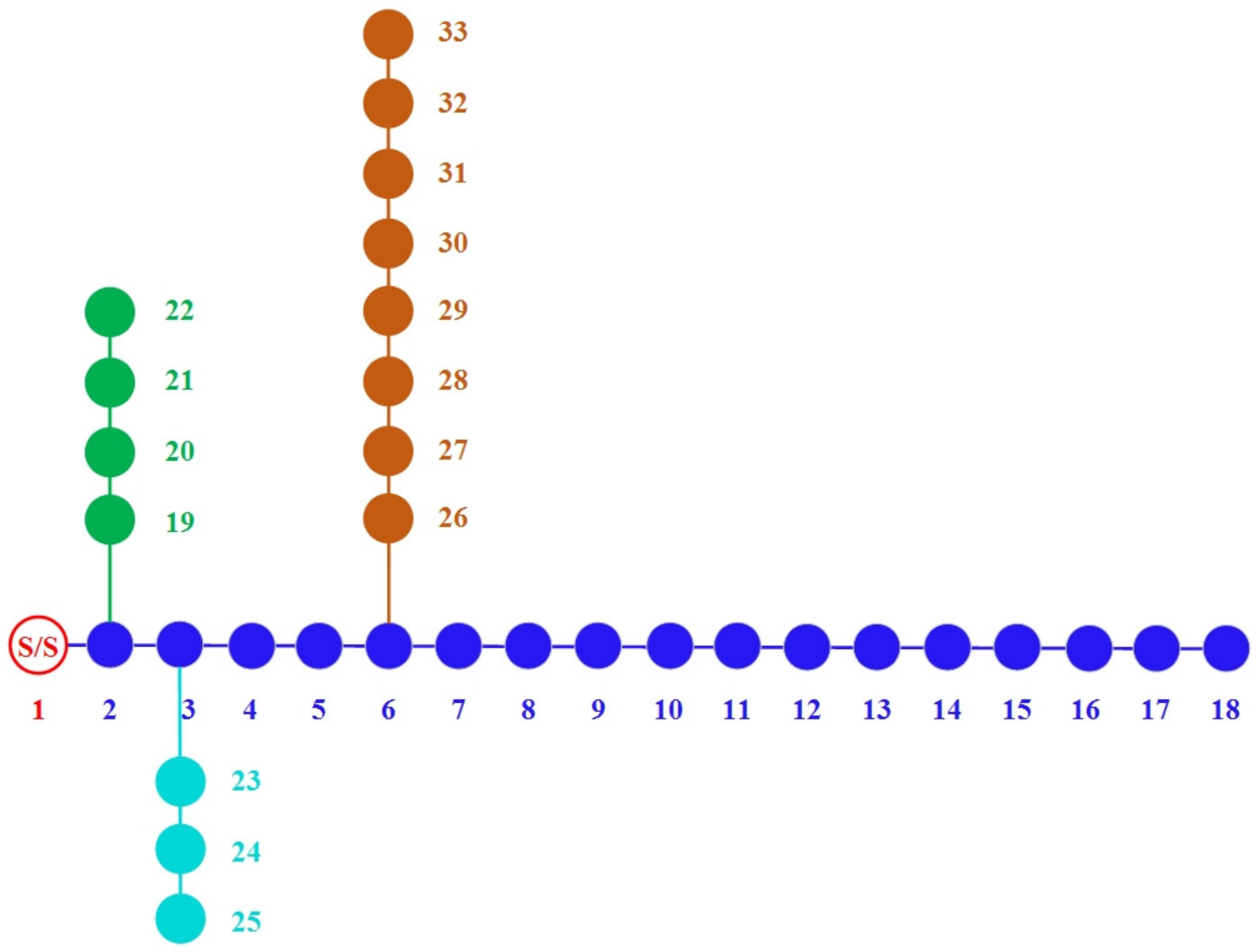
  • The performance of the methodology proposed is verified using the typical IEEE 33-bus test system to detect its superiority for handling the problems and compare to other published approaches.
This paper is organized as follows: Section 2 illustrates the suggested methodology, formulates the load flow issue, and formulates the objective problems. Section 3 displays the simulated results and compares the proposed methodology to the other methods. The conclusions are driven in Section 4.

2. Materials and Methods

This section describes the detailed procedure adopted in this research. The relevant mathematical requirement for the implementation of the quasi-oppositional-based Aquila optimizer is presented.

2.1. The Aquila Optimizer

The Aquila optimizer was proposed in [2] to model the hunting behavior of Aquila birds. This entailed mimicking the agile nature, speed, large sturdy feet, and sharp talons of Aquila birds used in grabbing their prey during hunting. The four major types of prey hunting schemes devised by the Aquila birds were modeled, which are used depending on the hunting situation [2]. The first hunting scheme popularly used for hunting flying birds involves the Aquila bird flying at a high soar with a vertical stoop, in which success depends on the Aquila bird having a height advantage over its prey [2,3]. The second scheme involves the bird hovering around in a contour-like pattern at a low distance to the ground level and using a short glide-like attack on its prey, often used to hunt seabirds [2]. The third scheme involves a slow, low flight descent attack on prey, such as foxes, with slow speed and response. The last hunting scheme by the Aquila bird involves the direct grabbing of prey while walking on land. The intelligence of the Aquila bird gave it the flexibility of quickly varying its hunting scheme back and forth between the four hunting techniques. The success of this nature-inspired hunting process displayed by the Aquila bird serves as the motivation for the development of the Aquila optimizer algorithm for the purpose of optimization. Further details on the hunting movement pattern and theoretical mathematical formulation of it can be found in [2,3]. The optimization process of the AO begins by randomly generating the initial population, which comprises a set of randomly generated candidate solutions. A search scheme that tries to balance the exploration and exploitation of the search space towards converging at the best optimal solution using four strategies along the path repetition was adopted. These search strategies are expanded diversification, narrowed diversification, expanded intensification, and narrowed intensification.
The expanded exploration x 1 utilizes the high soar with the vertical stoop hunting scheme. This involves the Aquila bird flying at a high soar to explore and determine its search space area while identifying its prey and choosing the best hunting area. This is modeled mathematically [2] as shown in Equation (1).
x 1 t + 1 = x b e s t t × 1 t T + x M t r a n d × X b e s t t
where the maximum number of iterations is represented as T and t is the current iteration whose next iteration solution x 1 ( t + 1 ) is obtained through the first search in the population of the candidate solution x 1 , and x b e s t ( t ) denotes the best solution obtained until the t th iteration. The number of iterations is employed to regulate the scope of the exploration of the search space using 1 t / T and x M ( t ) is the mean value of the locations of connected t th iteration current solutions, computed using Equation (2) for a given population size N of dimension size D.
x M t = 1 N i = 1 N x i t , j = 1 , 2 , , D
The narrowed exploration x 2 is characterized by the contour-like flight pattern with short glide attack in a narrowly explored search space for prey by the Aquila birds. This search method is used to obtain a solution X 2 ( t + 1 ) for the next iteration of t as expressed mathematically in Equation (3).
x 2 t + 1 = x b e s t t × L e v y D + x R t + y x × r a n d
where L e v y D is the levy flight distribution for the dimension space D and the random solution is x R ( t ) obtained at the i th iteration in the range of 1   N . The levy flight distribution is computed based on a fixed constant value s usually set to a value of 0.01, as well as a number picked at random between 0 and 1 for the parameter u and v as expressed in Equation (4).
L e v y D = s × u × σ v 1 β
where the parameter σ is computed using Equation (5), with a fixed constant parameter β set to 1.5.
σ = Γ 1 + β × sin π β 2 Γ 1 + β 2 × β × 2 β 1 2
The spiral shape in the search space as contained in Equation (3) is denoted by y   and   x and expressed in Equations (6) and (7), respectively.
y = r 1 + U D 1 cos ω D 1 + 3 π 2
x = r 1 + U D 1 sin ω D 1 + 3 π 2
where r 1 is assigned values between the range of 1–20 for a specified number of search iterations, and U and ω are assigned fixed values of 0.00565 and 0.005, respectively. D 1 is an integer number 1 to the length of the dimension D of the search space.
A slow, low flight descent attack is used by the Aquila bird to attack its prey, having accurately mapped out the prey area through the exploration process. This expanded exploitation x 3 is mathematically expressed as shown in Equation (8).
x 3 t + 1 = x b e s t t x M t × α r a n d + u b l b × r a n d + l b × δ
where the next iteration of the t solution is denoted by x 3 ( t + 1 ) , the best solution obtained until the i th iteration is denoted by x b e s t ( t ) , and x M ( t ) is the mean value of the present solution computed based on Equation (2). The adjustment parameters α and δ are usually assigned a value of 0.1 each and the random number generated between 0 and 1 is assigned to rand. The upper and the lower bound are denoted by u b and l b , respectively.
The last hunting scheme used by the Aquila birds involves the direct grabbing of prey based on their random movement pattern while working on the land. This hunting scheme was used for the design of the narrowed exploitation x 4 used to generate the t th iteration of the next solution x 4 ( t + 1 ) , as expressed in Equation (9). A balance between the search scheme was ensured by the introduction of a quality function, Q F , as expressed in Equation (10).
x 4 t + 1 = Q F × x b e s t t G 1 × r a n d × x 1 t G 2 × L e v y D + r a n d × G 1
where G 1 and G 2 denotes the Aquila prey tracking motion pattern and the flight slope to attack during elopement from the initial location to the last location, respectively, computed using Equations (11) and (12) where t is the current iteration and the maximum iterations are represented as T .
Q F t = t 2 × r a n d ( ) 1 1 T 2
G 1 = 2 × r a n d 1
G 2 = 2 × 1 t T
The Aquila optimization process is summarized in the pseudocode in Algorithm 1 [15].

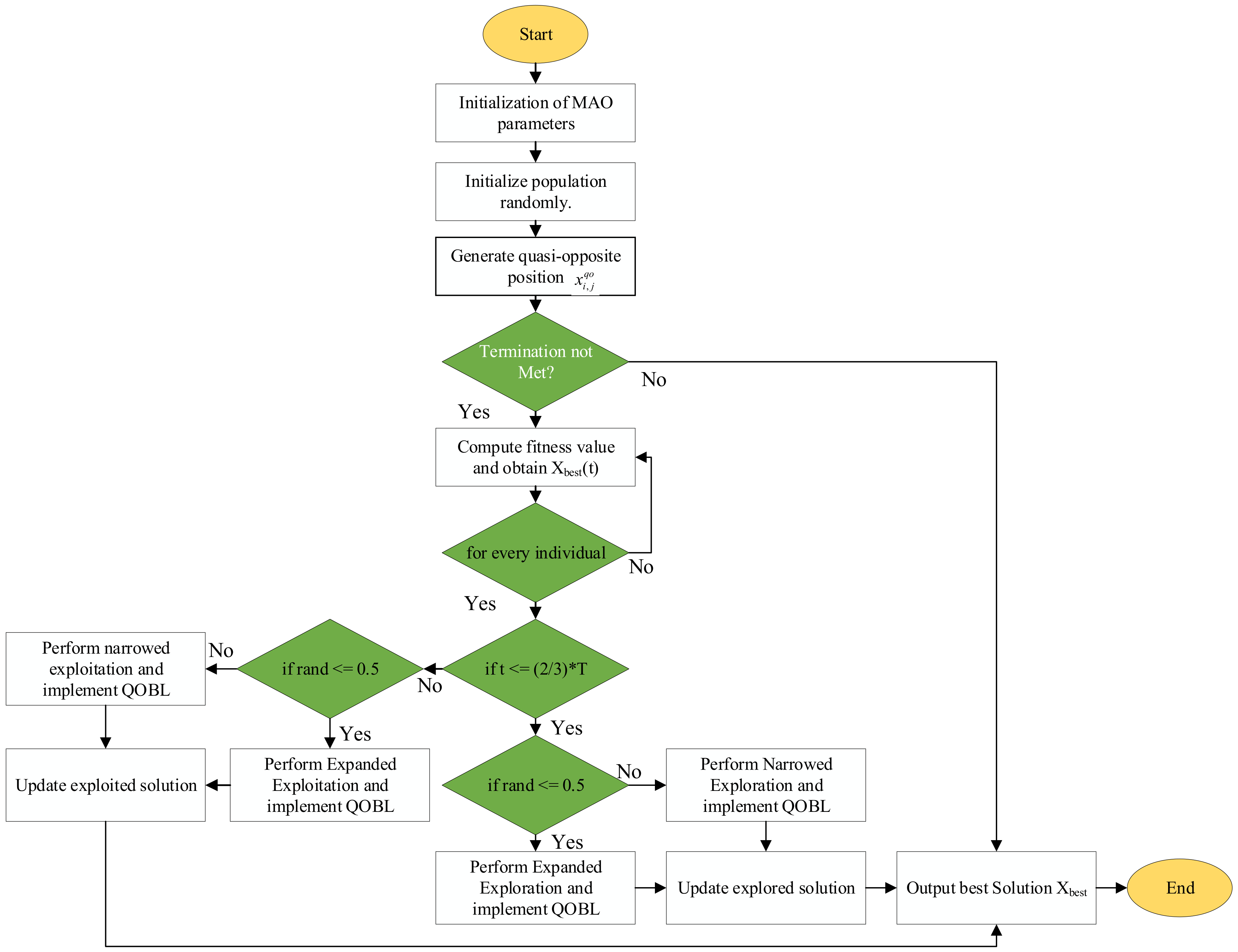
2.2. The Proposed Modified Aquila Optimizer

The search operator quasi-oppositional-based learning (QOBL), which was used to improve the initialization of the AO and local searching at the end of the AO algorithm, is described as follows.

2.2.1. Oppositional and Quasi-Oppositional-Based Learning

The OBL is a mathematical operator which was introduced for improving the performance of modern optimization algorithms. As proposed by Tizhoosh, the OBL is based on the idea that the probability of the opposite numbers to obtain a fitter solution is higher than random numbers [36]. Various studies have shown that OBL has improved the performance of numerous population-based optimization algorithms in terms of solution accuracy and convergence speed. Despite the encouraging results of OBL in various studies, the method had been modified to become quasi-oppositional-based learning [34]. The QOBL shows that using a quasi-opposite number is more effective than the opposite number in determining optimal results to an optimization problem. In QOBL, both the present nominee population, its opposite population, and its quasi-opposite population are used to form the fittest population. Assuming x is a 1-dimensional real number in the hyperspace. Let the opposite number be x 0 and the quasi-opposite number be x q 0 of x , defined as:
x 0 = l b + u b x
where x and x [ l b , u b ] .
x q 0 = r a n d l b + u b 2 , x 0
Algorithm 1: Aquila Optimizer
Mathematics 10 02129 i001

2.2.2. Opposite Points and Quasi-Opposite Points

Assuming x x 1 , x 2 , , x n is a 1-dimensional point in the optimization hyperspace, then, the opposite point x 0 x 1 0 , x 2 0 , , x n 0 and quasi-opposite point x q 0 x 1 q 0 , x 2 q 0 , , x n q 0 can be computed by:
x i 0 = l b i + u b i x i
where x i and x i l b i , u b i i 1 , 2 , , n .
x i q 0 = r a n d l b i + u b i 2 , x i 0
In this paper, the QOBL was used in the population initialization of the original Aquila optimization algorithm. Concurrently, both the present population and the quasi-opposite population were utilized to generate a fitter population. This enables the AO to hurdle to a new nominee of the solution that has a fitter fitness value. The pseudocode in Algorithm 2 describes the procedures of the implemented quasi-oppositional-based learning.
Algorithm 2: Pseudocode of quasi-oppositional-based learning
Mathematics 10 02129 i002
The QOBL strategy described in Algorithm 2 was incorporated into the original AO algorithm to establish the modified Aquila optimizer. After randomizing the initial population of the AO, the QOBL was implemented to obtain a new, improved initial population. Thereafter, each step of the AO was implemented. For each step of the AO, the QOBL was reimplemented to guarantee a better balance amid diversification and intensification and to ensure that the best solution was obtained. This process was repeated until termination criteria were met. The detailed procedure of the MAO is given in Algorithm 3.
Algorithm 3: Pseudocode of the MAO algorithm
Mathematics 10 02129 i003
The flowchart for implementing the quasi-oppositional-based Aquila optimizer is given in Figure 1 as follows.

2.3. Methods of Evaluation

This section is further separated into two subsections. In the first subsection, the procedures used to evaluate the performance of the modified Aquila optimizer on twenty-three competition on evolutionary computation (CEC) benchmark functions in addition to the original Aquila optimizer are presented. The second subsection provides detailed procedures on the application of the modified Aquila optimizer on engineering problems.

2.3.1. The CEC Benchmark Functions’ Description

Performance of the developed modified Aquila optimizer was evaluated using twenty-three benchmark functions of diverse properties. The twenty-three commonly used benchmark functions used in this paper were organized into three separate groups. The first group which comprises seven multidimensional, unimodal benchmark functions in the range of F1–F7 is given in Table 2. The second group given in Table 3 comprises six multidimensional multimodal benchmark functions in the range of F8–F13. The last group comprises benchmark functions of different dimensionality ranging from F14–F23 as shown in Table 4. Detailed information about the test functions can be found in [2].

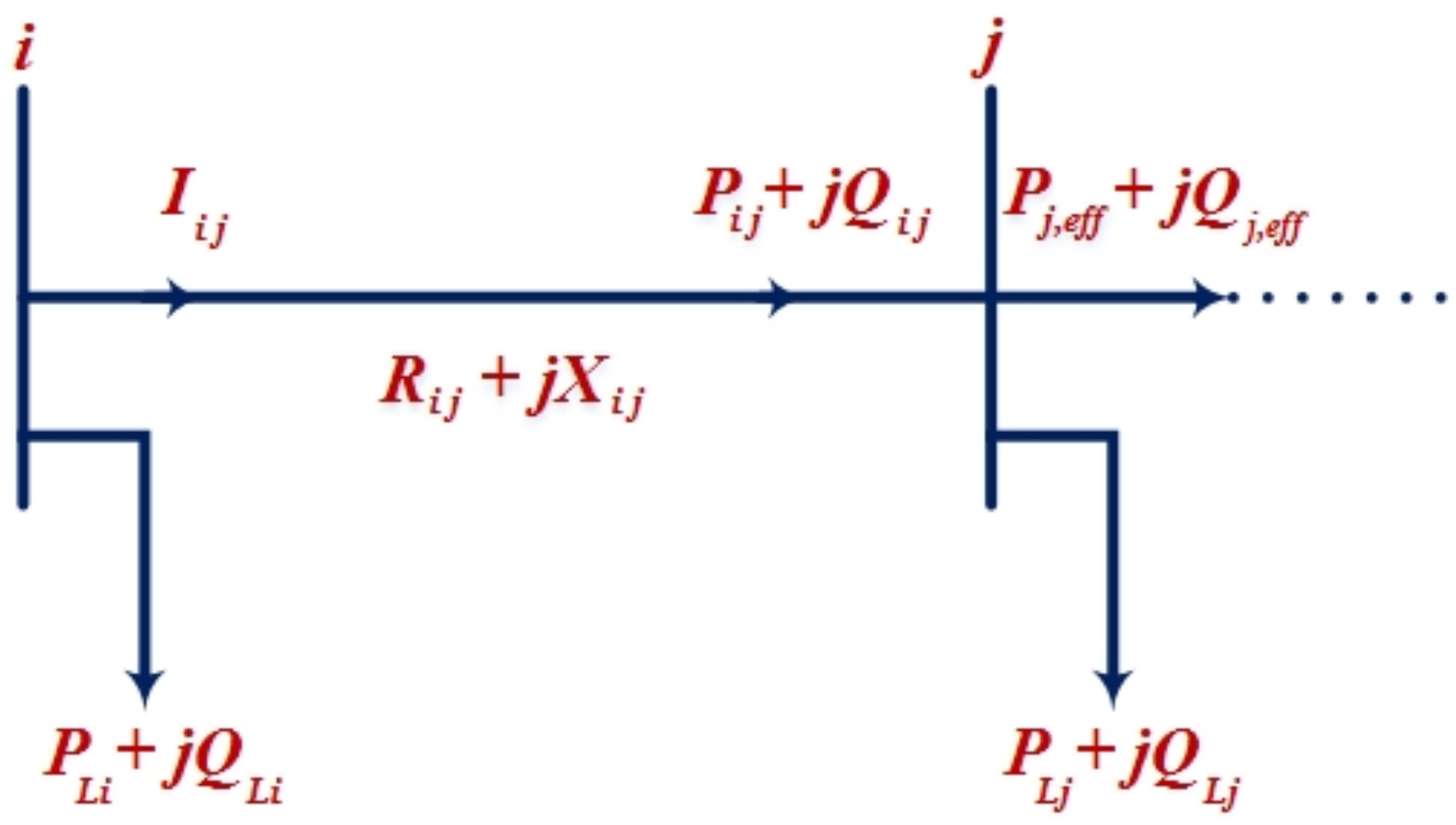
2.3.2. Load Flow Formulation for Optimal Distributed Generation Allocation

For load flow evaluations, the BFS approach was used [9]. Figure 2 is a scale model of a radial distribution network. It is assumed that the N th line connects nodes “ i ” and “ j ”. The BFS algorithm’s implementation may be inferred in two stages using Kirchhoff’s law. The convergence is faster if the largest discrepancy within bus voltages is less than 0.00001. As a result, the distribution grid’s active and reactive power loss is easily calculated. These stages are as follows:
A.
The power flow from the ith to jth nodes is expressed as the following equations depending on the direction of the backward sweep from the last node.
P i j = P j + R i j P j 2 + Q j 2 V j 2
Q i j = Q j + X i j P j 2 + Q j 2 V j 2
P j = P L j + P j ,   e f f
Q j = Q L j + Q j ,   e f f
where P L j   and Q L j are connected loads at the jth node.
The forwarding sweep direction can be calculated using the voltage at the i th and j th nodes, and the nodal current via the branch-sample with an impedance Z i j = R i j + j X i j connected with i th and j th nodes can be calculated as follows:
I i j = V i δ i V j δ j R i j + j X i j
o r   I i j = P i j Q i V i δ i  
The voltage at the   j th node is provided by Equations (21) and (22), as follows:
V j = V i 2 2 × P i R i j + j Q i X i j + R i j 2 + X i j 2 × P i 2 + Q i 2 V i 2 0.5

2.3.3. Problem Formulation

The key issue here is determining the ideal sizes and locations of DGs to be installed on buses, which may be accomplished using the MAO algorithm. In load flow simulation, the DG units are considered as a negative P Q load. To begin, it is believed that all system buses, with the exemption of the substation bus, are candidates for DG placement. Using an objective function as in (24), the DG locations and sizes are considered as the control variables, and their optimal values are achieved through the proposed algorithm. The best selection of DG is found using an MO function, which is a weighted sum of a single-OF.
A.
Objective function (OF)
The ODGA problem’s goal or fitness function seeks to reduce power losses and voltage variations while adhering to equality and inequality restrictions [9]:
O F = m i n W 1 × P L + W 2 × V D  
where P L is the real power loss, V D   is the voltage deviation, and W 1 and W 2 are adaptive weights of power loss minimization and voltage deviation, respectively; W 1 0 , W 2 0 , and W 1 + W 2 = 1   for multi-objective function [26]. The specific variables, P L , and V D , are as follows.
I.
Real power loss ( P L )
The overall real power losses of the system are given by:
P L = k = 1 N l G k V i 2 + V j 2 2 V i V j cos δ i δ j
where N l is the total of the transmission lines; G k is the conductance of the line k ; V i   and V j   are the line voltages at the sending and receiving ends, respectively; and δ i and δ j   are voltages angles.
II.
Voltage deviation ( V D )
To guarantee quality service, the bus voltage magnitude is kept within the permitted limit. The voltage profile is enhanced by limiting the variance of the load bus voltage, as illustrated in Equation (26):
V D = i = 1 n 1 V i
where n   is the total system buses.
B.
Constraints
The restrictions that ensure the system’s exceptional performance are classified as technical and operational constraints, which determine the minimization of the objective function.
I.
Operational constraints
They are known as equality constraints which formulate the active and reactive power balance by load flow equations, as given below:
P G i P D i V i j = 1 n V j G i j cos θ i j + B i j sin θ i j = 0   ,   i     n
Q G i Q D i V i j = 1 n V j G i j sin θ i j + B i j cos θ i j = 0 ,   i     n
where P G and Q G   are the real power and reactive power generation, P D   and Q D are the real and reactive load demand, G i j   and B i j   are the mutual conductance and susceptance between bus i   and bus j , and θ i j   is the voltage angle difference between bus   i   and bus   j .
II.
Technical constraints
They are known as inequality constraints and can be divided into:
  • Voltage constraints
    V i m i n     V i       V i m a x   ,   i     n
  • Current constraints
    I l i     I l i r a t e d   ,   i     b
  • DG size constraints
    P D G m i n P D G P D G m a x
    Q D G m i n Q D G Q D G m a x
  • DG location constraints
    2 D G l o c a t i o n n b u s
    where   V i m i n and V i m a x are the voltage boundaries at bus i ,   I l i is the line current flow of line i , and   I l i r a t e d is the rated line current transferred.

3. Simulation Results

This section provides a detailed comparative study of the developed quasi-oppositional-based learning Aquila optimizer, called the MAO, and the original AO on twenty-three CEC benchmark functions and ODGA engineering problems. The results and discussion on the benchmark function, which comprises the solution accuracy and convergence analysis of both the MAO and AO on the CEC benchmark functions, is presented in Section 3.1, whereas the performance of both algorithms on the ODGA engineering problem is presented in Section 3.2. In both the CEC benchmark functions and the ODGA engineering problem, the MATLAB R2020b simulation platform was used on a personal computer running Windows 10, 64-bit operating system with Intel(R) Core (TM) i7-8550U CPU @ 1.80 GHz 1.99 GHz, 16 GB RAM.

3.1. Benchmark Functions Result Analysis

This section is sub sectioned into two parts. The first part describes the solution accuracy of the AO and MAO on the benchmark functions, whereas the convergence accuracy of the algorithms is described in the second subsection.

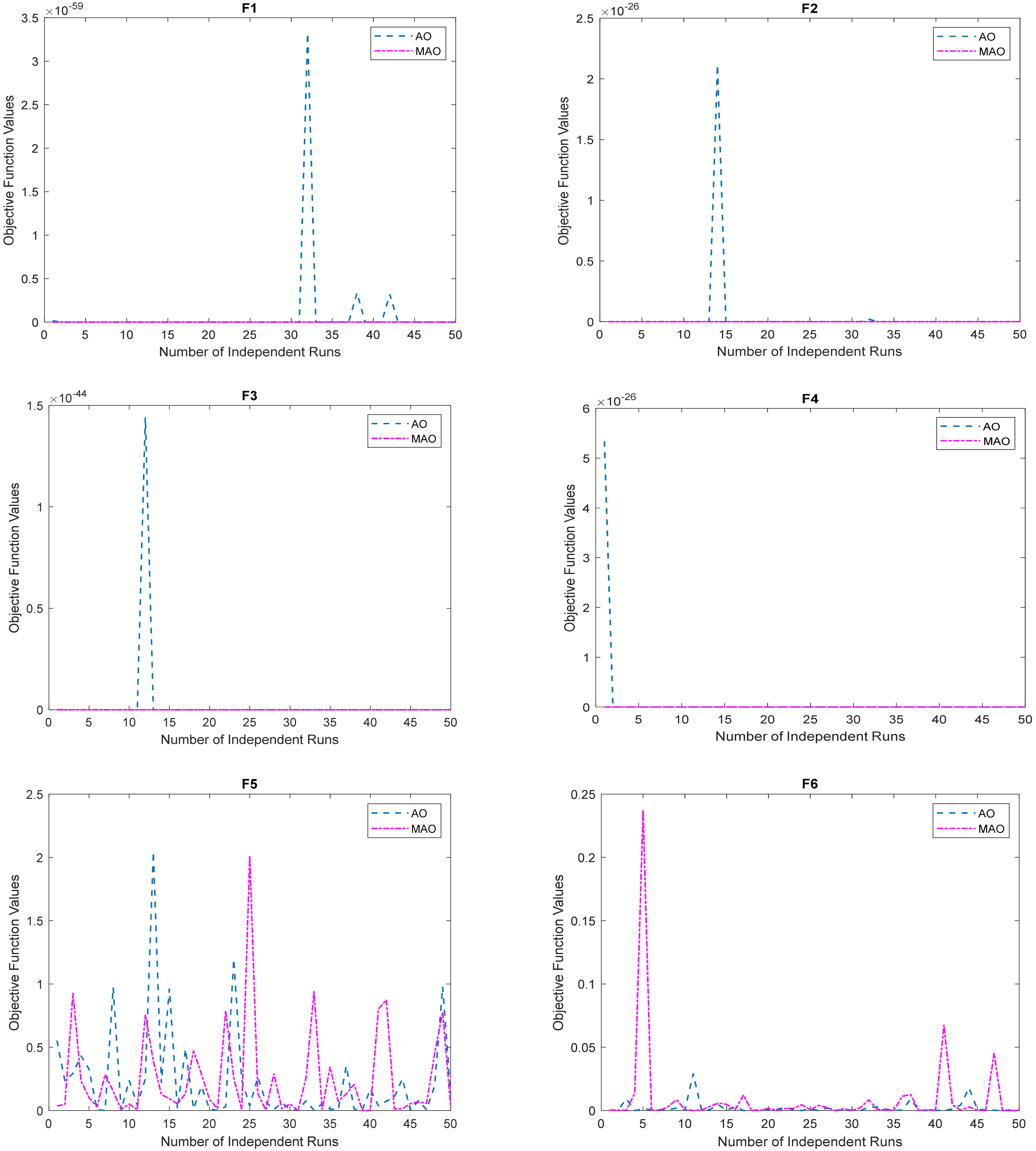
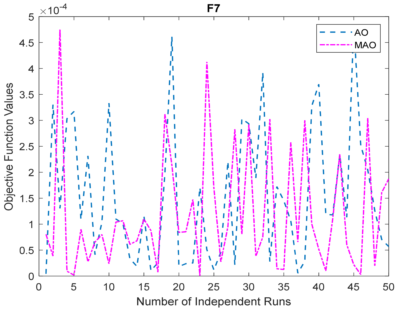
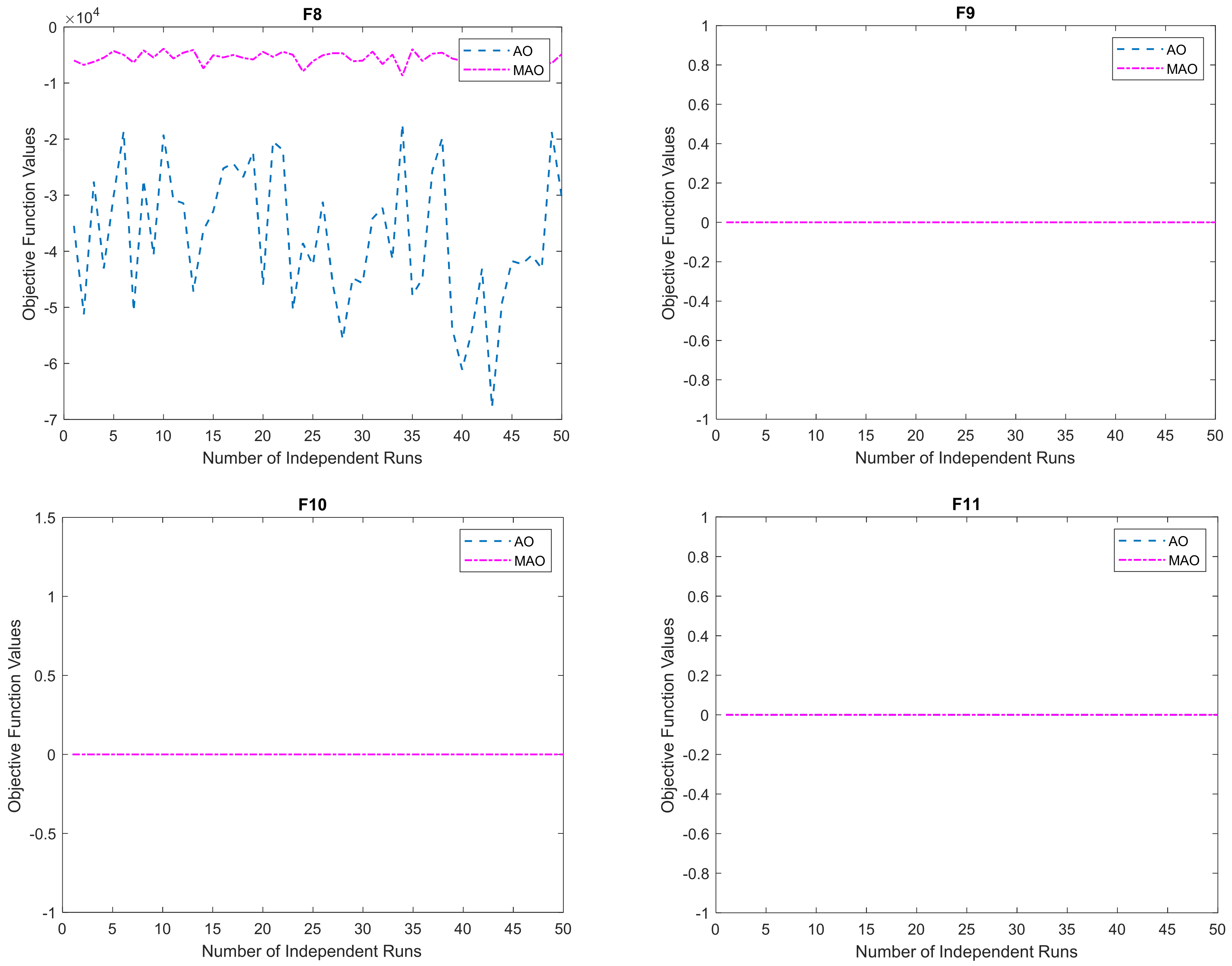
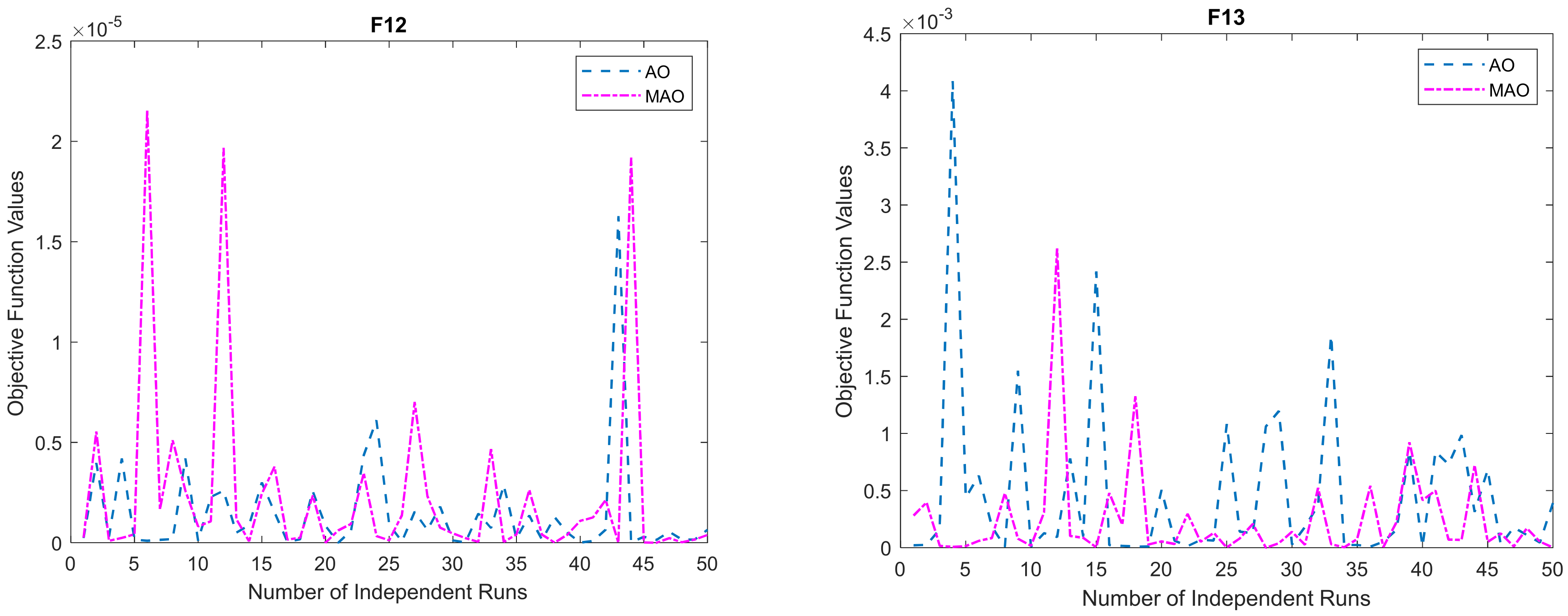
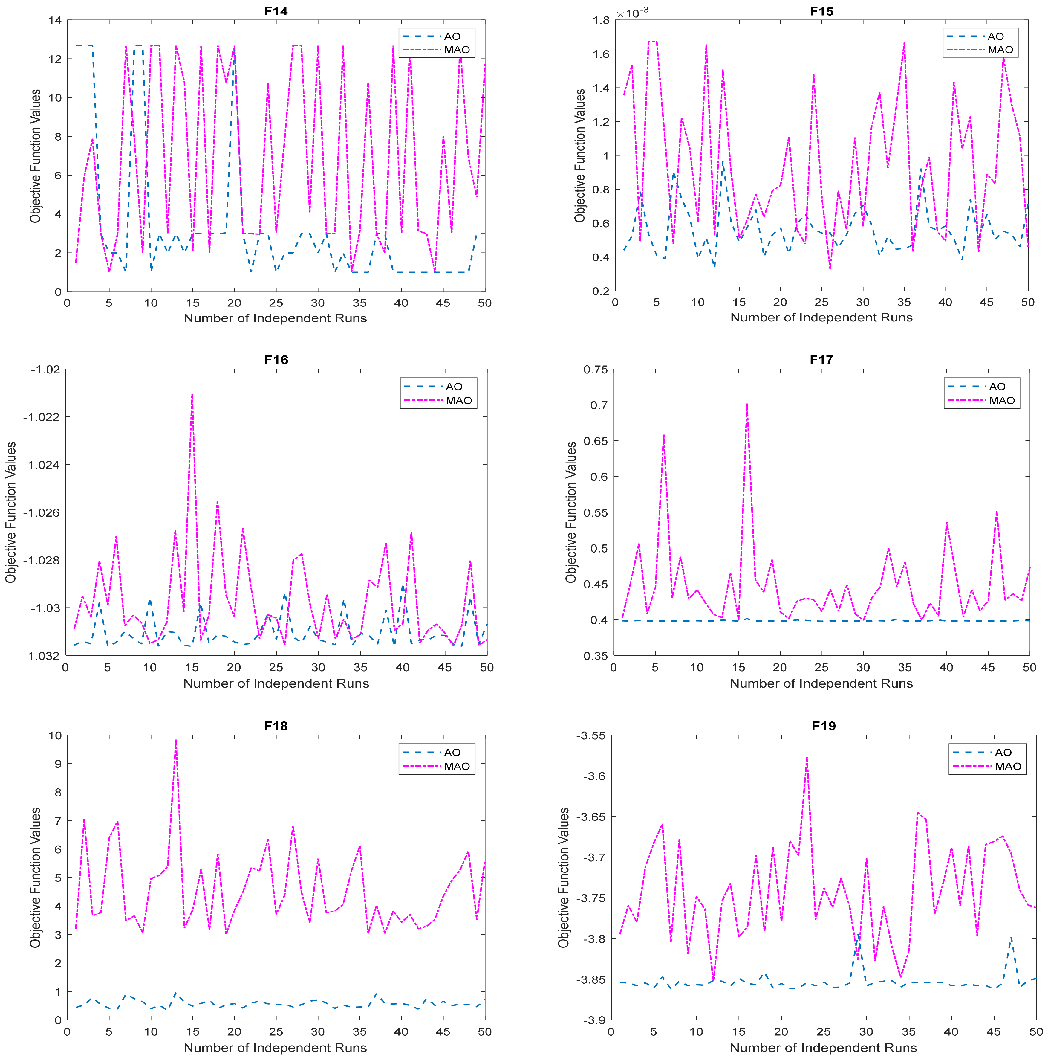
3.1.1. Solution Accuracy

The MAO and original AO algorithms were implemented on the twenty-three benchmark functions described in Section 2.3. The benchmark functions were grouped into three categories, namely, unimodal, multimodal, and fixed-dimensional benchmark functions. To ensure a good level of comparison, we retained the same algorithm parameters presented in the original AO algorithm. Both the MAO and AO were implemented for 200 iterations using 50 search agents. To examine the computational complexity of the MAO with respect to AO, we implemented the algorithms on the unimodal and multimodal functions by considering 10, 50, 100, and 500 dimensions. The results obtained for each dimension are presented in Table 5, Table 6, Table 7 and Table 8. Table 5 gives the results obtained for both unimodal and multimodal benchmark functions considering 10 dimensions. The same results obtained for 50, 100, and 500 dimensions are presented in Table 6, Table 7 and Table 8, respectively.
For the fixed-dimensional CEC functions, the results obtained are given in Table 9. In each CEC benchmark function, the best, average, worst, and standard deviation of the computations after 50 independent runs are presented. The simulation time taken by each algorithm to obtain their respective optimal results is also given in each table as nTI. From the tables, the values in bold give the best results obtained by either the MAO or AO. The values in bold italics are used to represent a situation where both the MAO and AO obtained the same results for any of the benchmark functions.
From the result tables, it can be observed that for the set of unimodal benchmark functions (F1–F7) the modified optimizer, MAO, demonstrated its superiority over the standard AO in all the functions when ten-dimensional variables were considered. For the set of multimodal functions (F8–F13), the MAO also showed superior performance by obtaining the best results in F8 and F13 and jointly obtaining the best results in F9–F11. The AO only performed better in this scenario in F12. When fifty-dimensional variables were considered, the MAO also showed superior performance over the AO in F1–F4 unimodal benchmark functions, whereas the AO marginally performed better in F5–F8 unimodal functions. Considering the same dimensional variables for the multimodal benchmark functions, the MAO obtained the best results in F12 and F13 whereas the AO obtained the best results only in F8. Both algorithms, however, obtained the same results in F9–F11. For the one-hundred-dimensional variables, the MAO showed very good performance in all the unimodal benchmark functions by performing better than the AO in all the seven benchmark functions. For the multimodal functions of these dimensional variables, the MAO also showed better performance over the AO by obtaining the best results in F8 and F13, where the AO obtained the best result only in F12. For this dimensional variable, both algorithms obtained the same results in F9–F11. Similarly, for 500-dimensional variables, the MAO also demonstrated its superiority over the AO by obtaining the best results in all the unimodal functions. For the multimodal functions, the MAO also obtained the best results in F8 and F11–F12, whereas both algorithms jointly obtained the same results in F9–F11. These results are a demonstration that irrespective of the size of the search space, the modified optimizer maintained a superior performance over the original AO on unimodal and multimodal functions.
When applied to the CEC benchmark functions of fixed dimension in the range of F14–F23, the modified optimizer, MAO, obtained the best results in F14, F17, and F19–F20. For these function groups, the original AO obtained the best result in the F15, F18, and F21–F23 benchmark functions. However, both the MAO and AO obtained the same results in the F16 benchmark function. This is also a demonstration that the MAO can effectively solve the benchmark functions of a fixed dimension in comparison with the standard AO.
To examine the robustness and superiority of the results of any of the algorithms over the other, the Wilcoxon rank-sum nonparametric study was conducted using the 50-independent runs performed in this paper. This test was conducted as a benchmark where none of the algorithms obtained exactly the same results or exactly the same global solution. This is because the nonparametric test for two equal samples of the same size is not a real or complex number. Thus, this paper carried out the Wilcoxon rank-sum test at a significant probability level of 5% (p-value = 0.05) for the benchmark function results of 50 dimensions and fixed dimensions as shown in Table 10.
From Table 10, when a p-value ≤ 0.05 and corresponded to a null hypothesis, where h-value = 1, then the difference in solution sets obtained by either of the algorithms over the other was significant. Similarly, if the p-value > 5 and the h-value = 0, the solution quality obtained by either of the algorithms over the other was not significant. From the table, it can be observed that for functions where none of the algorithms obtained the same results, the MAO dominate AO, especially for F2–F6, F14, F16–F17, and F20. Similarly, F8, F15, F21, F22, and F23 showed that the results obtained by the AO dominated MAO for these functions. However, for F1, F7, F12 and F13, results showed nonsignificant performance of any of the algorithms over the other by obtaining an h-value of 0.

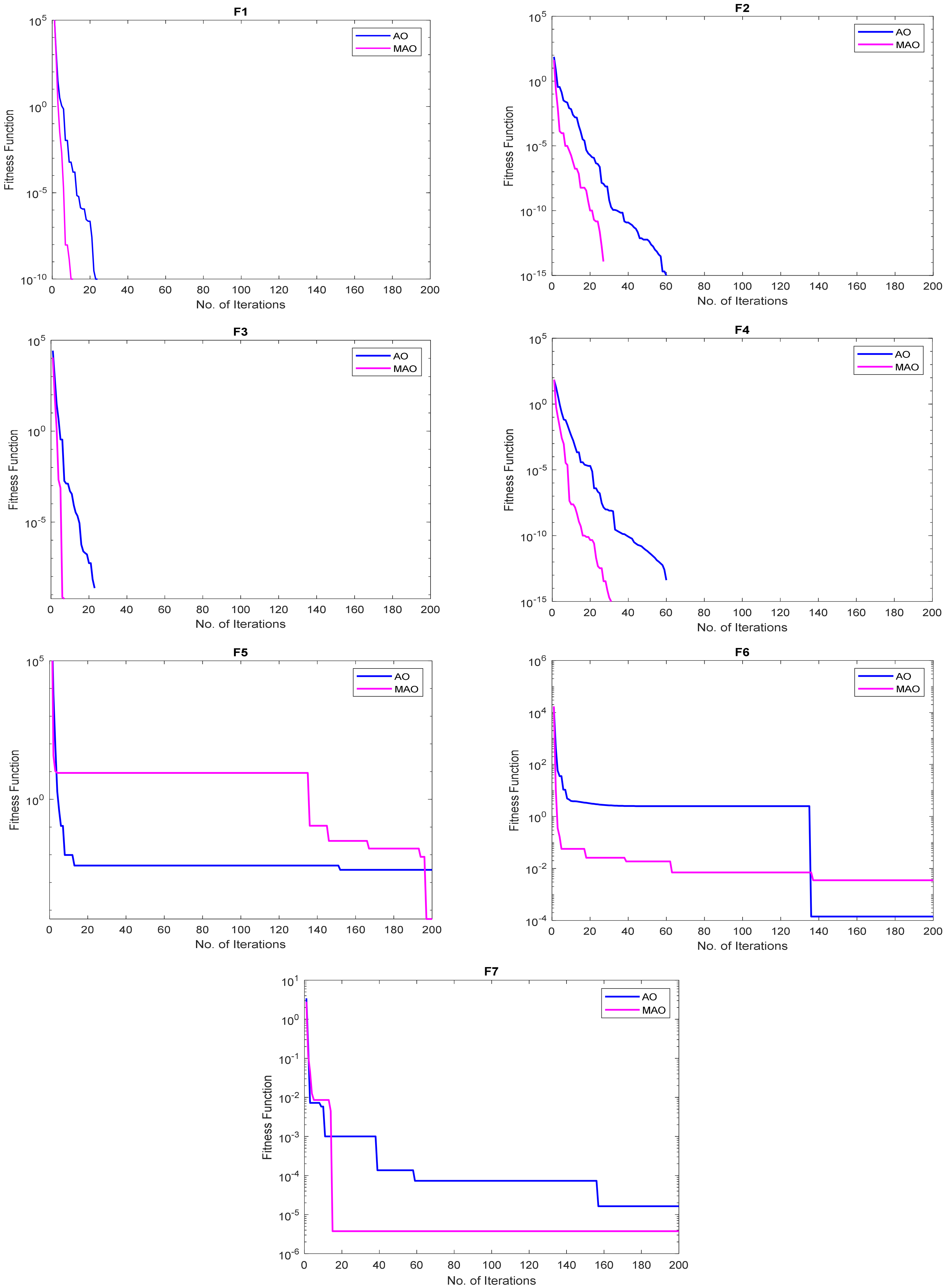
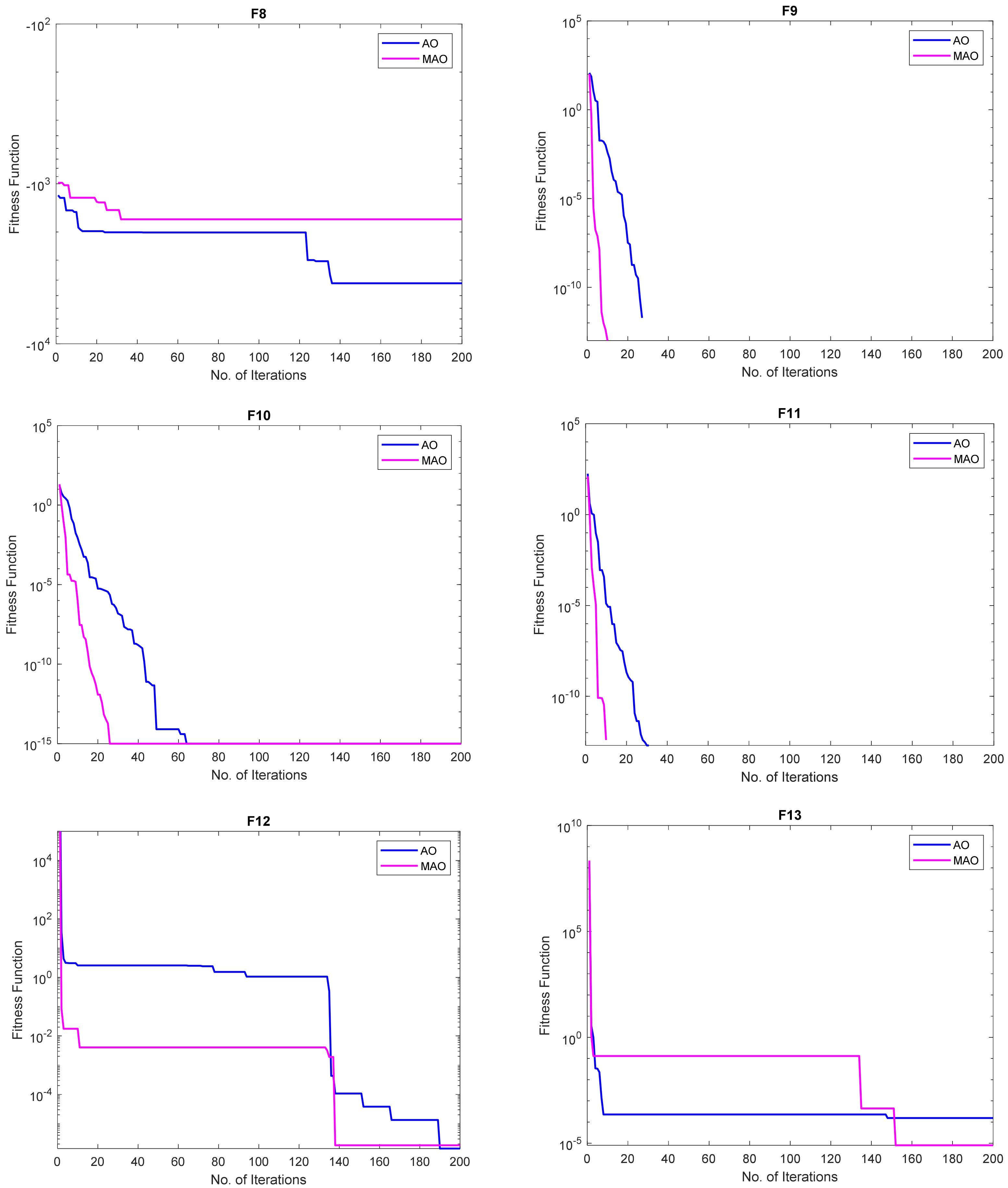
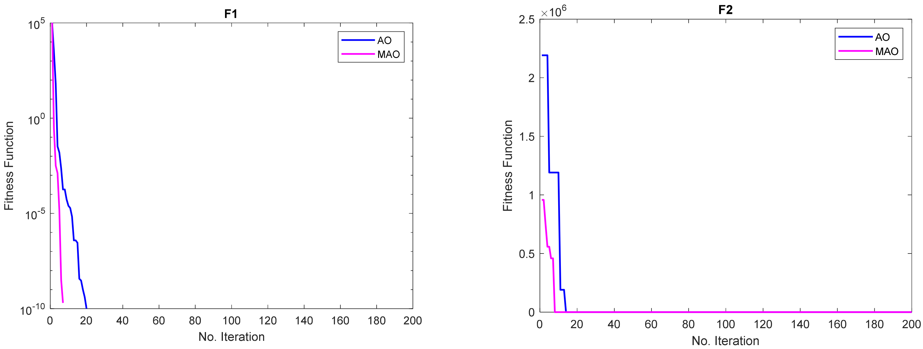
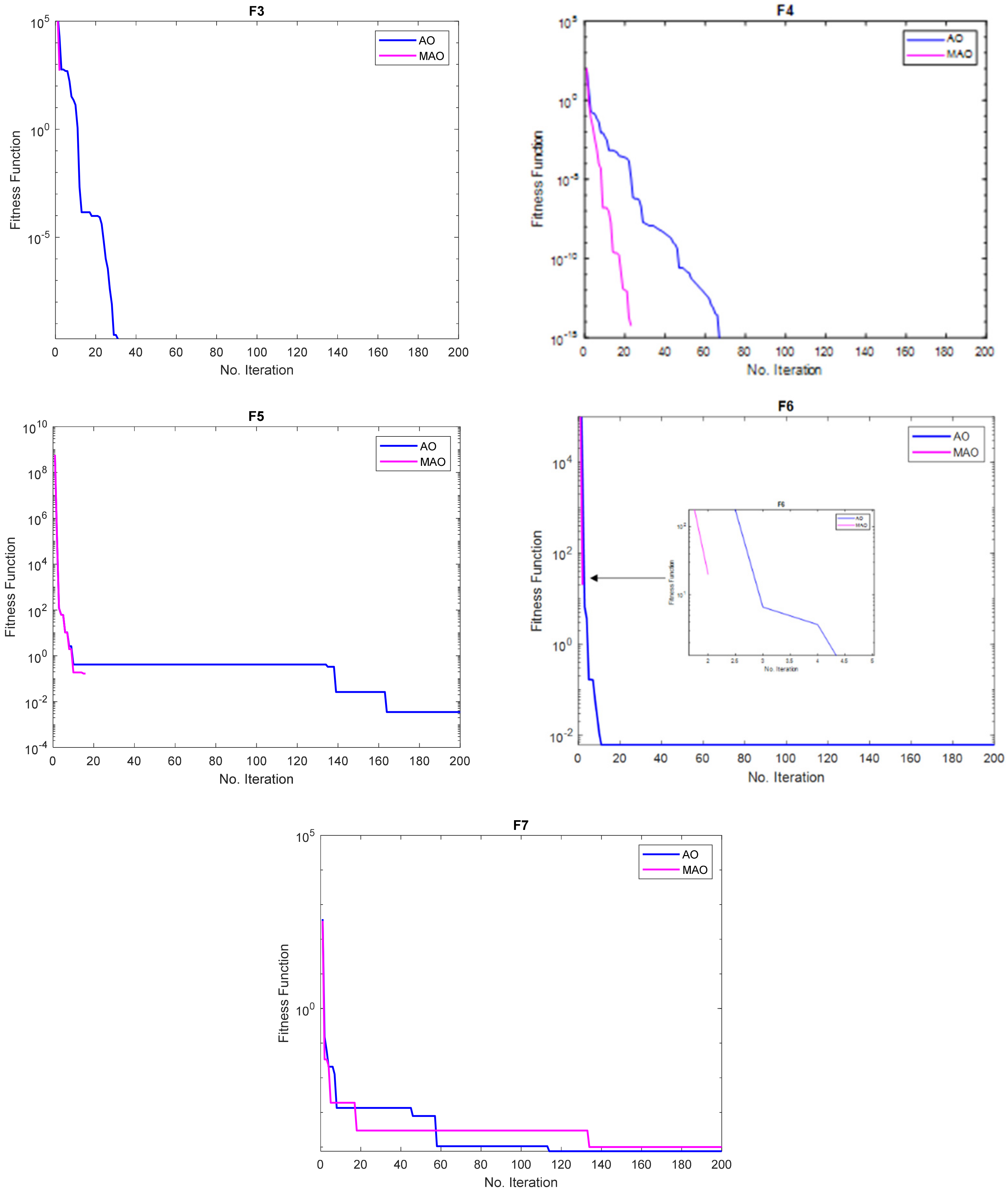
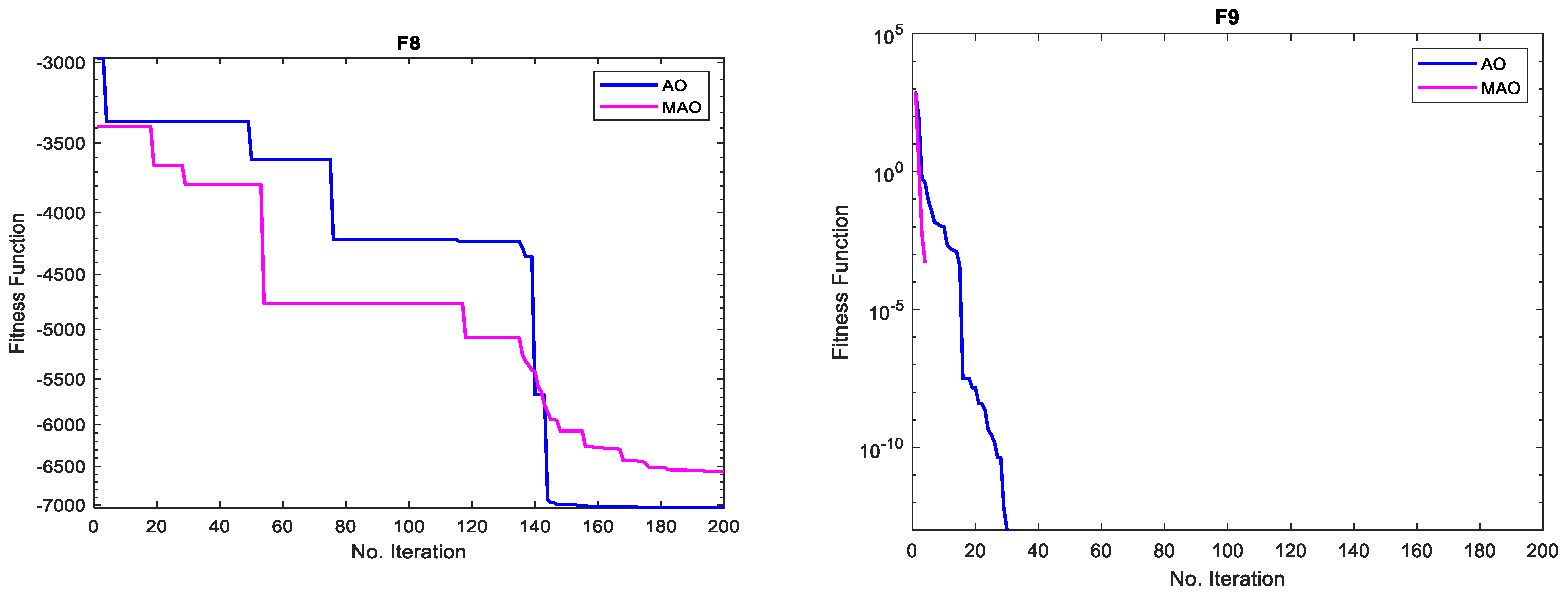
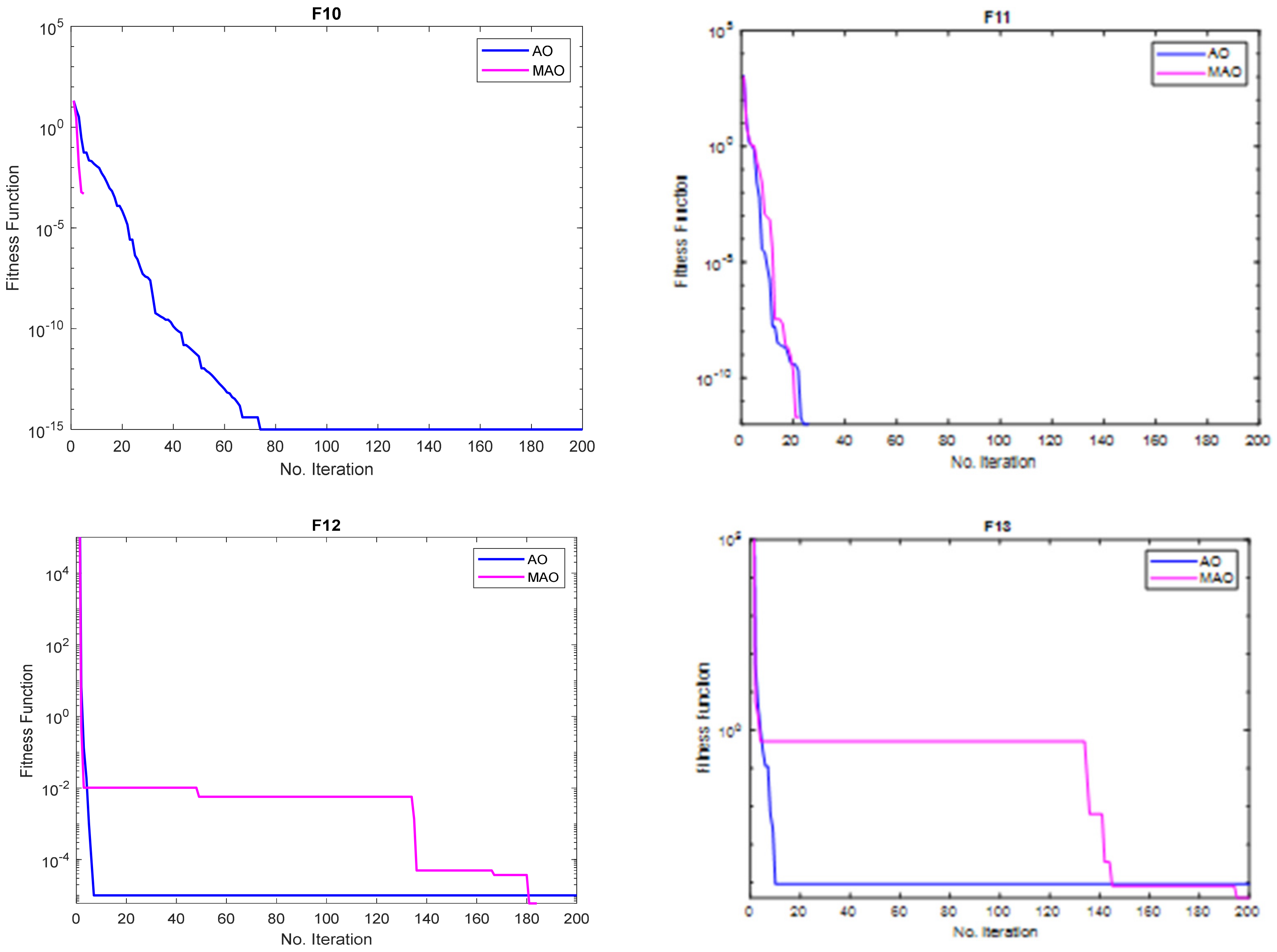
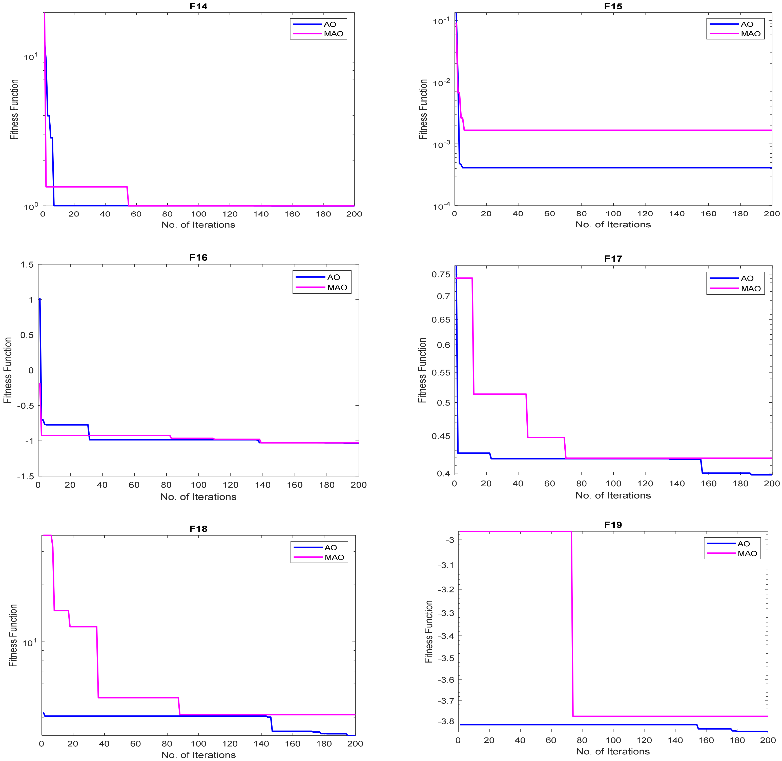
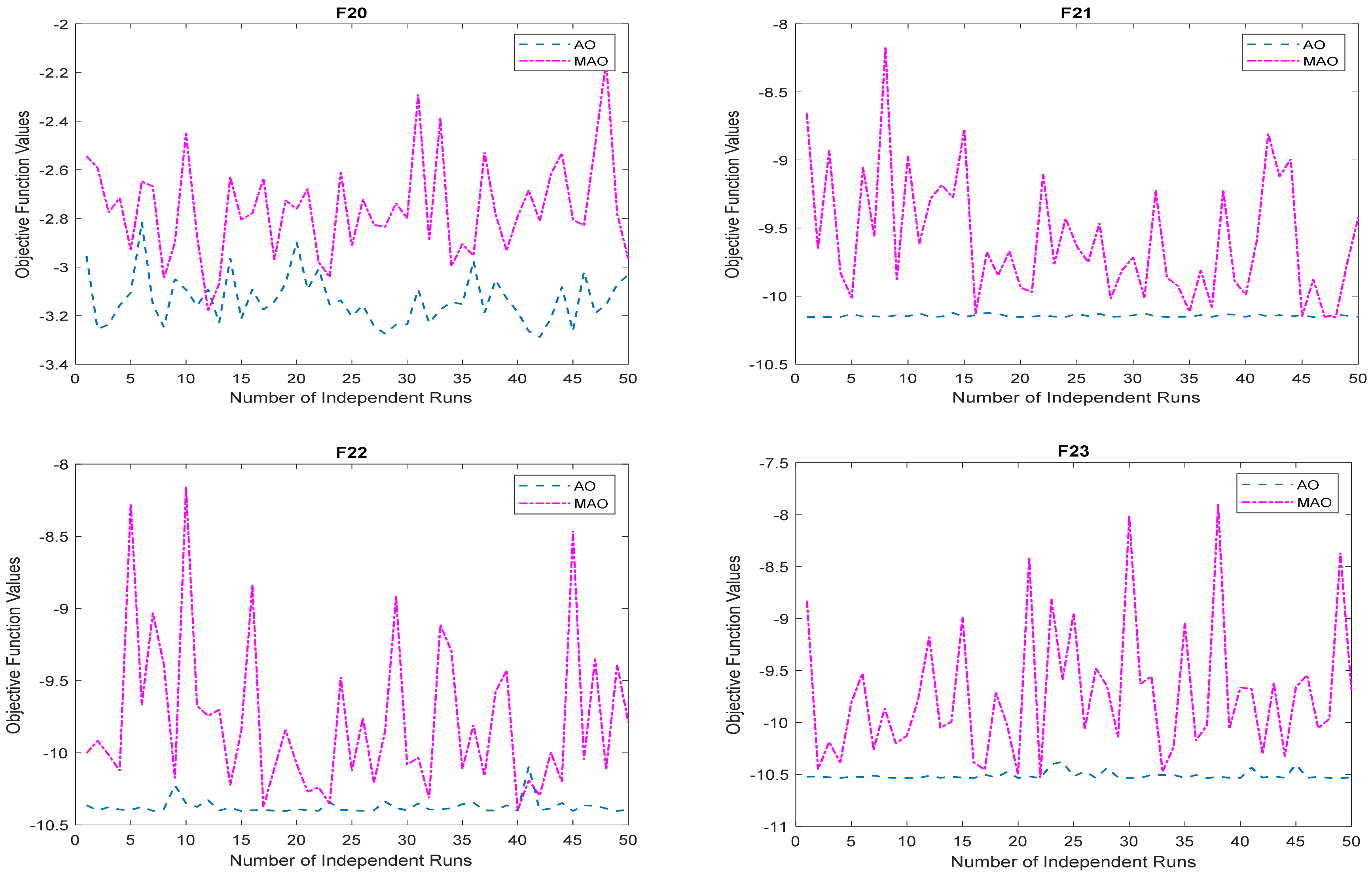
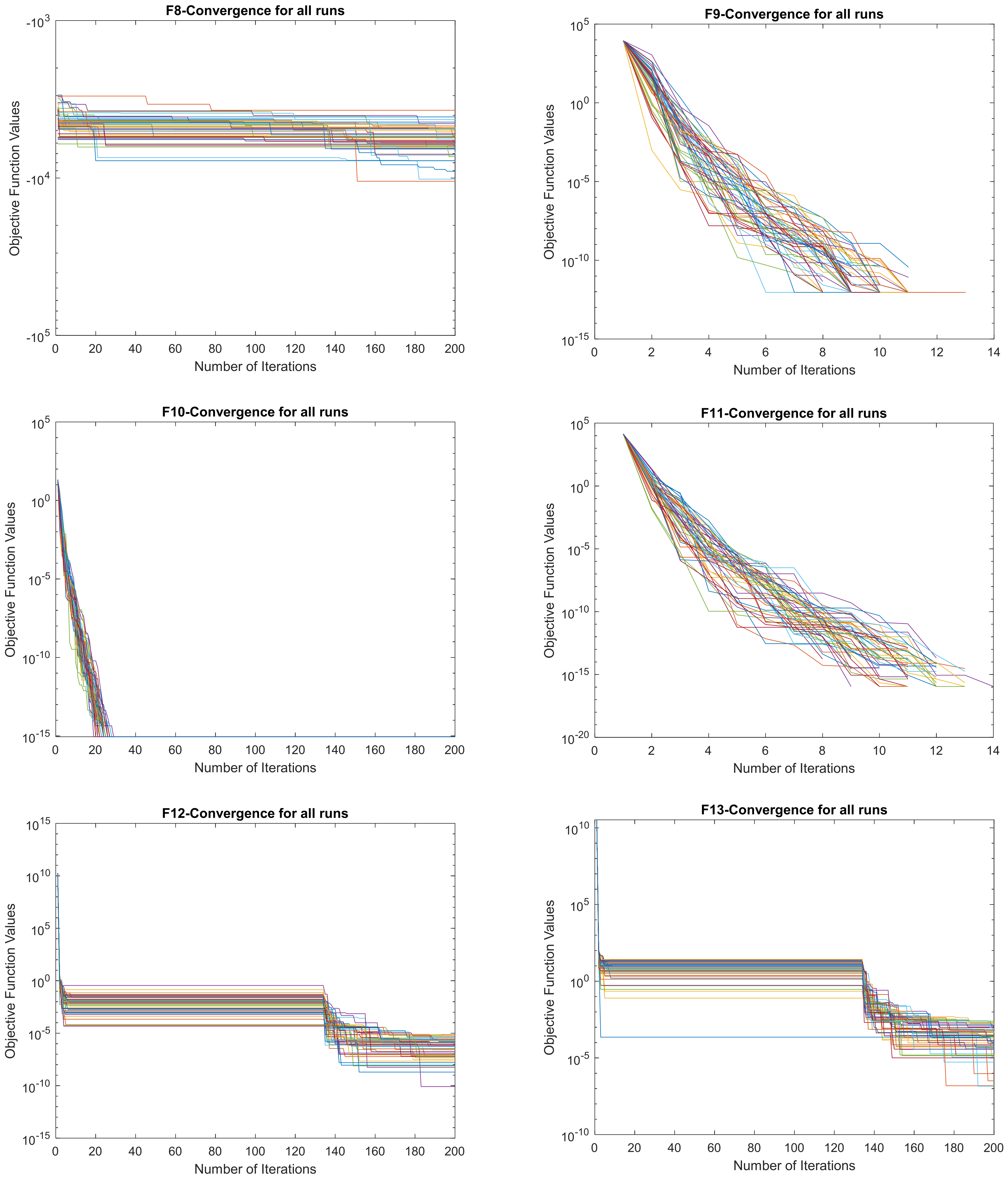
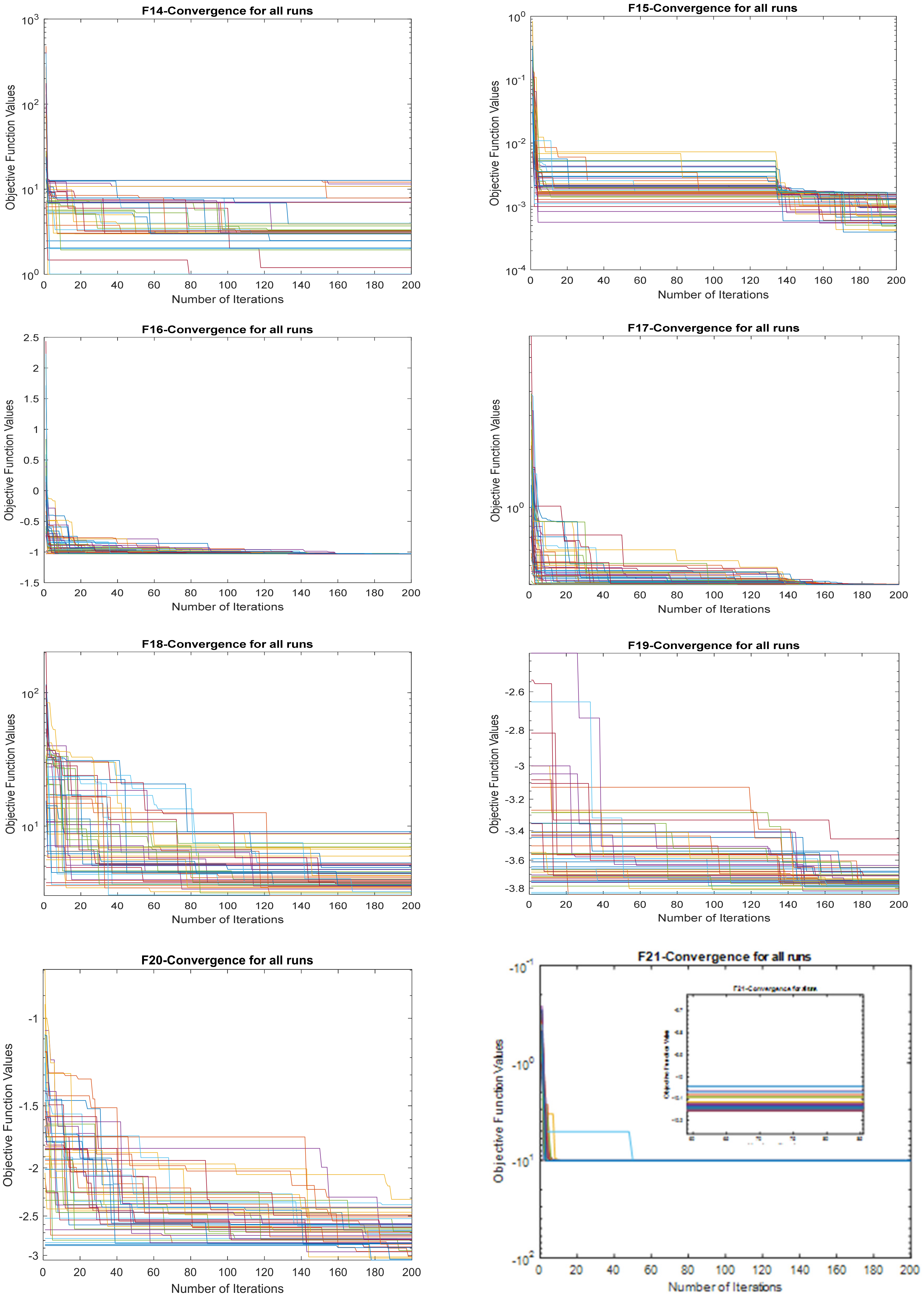
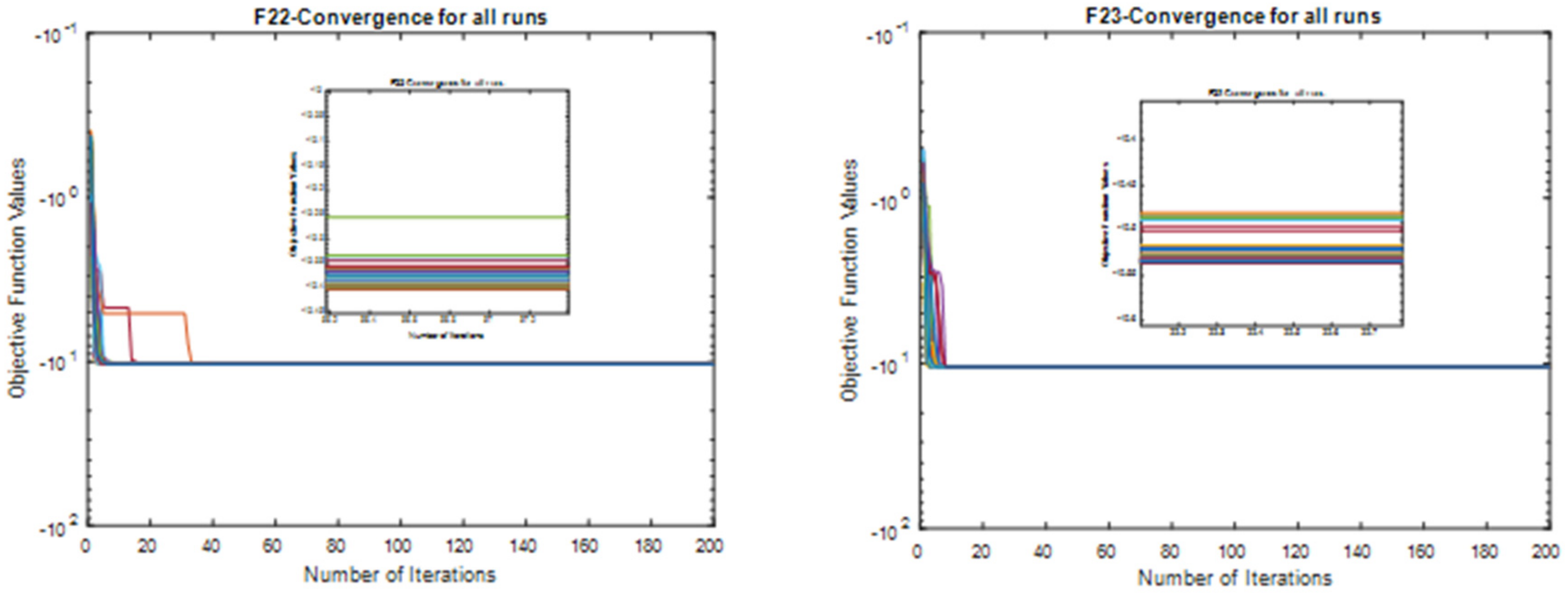
3.1.2. Convergence Study

To effectively analyze the convergence of both the MAO and AO, and to avoid unnecessary repetition of convergence, the convergence characteristics of both algorithms on ten- and fifty-dimensional variables are considered in this paper. Since the benchmark functions considered in this paper are organized into three different categories, we present the convergence plots according to these categories. For example, Figure 3 shows the superimposed convergence plots of the MAO and AO on unimodal functions considering ten-dimensional variables, whereas the convergence plots for both algorithms on the multimodal functions for the same dimensional variables are shown in Figure 4. For fifty-dimensional variables, the convergence characteristics for both unimodal and multimodal functions are presented in Figure 5 and Figure 6, respectively. Finally, the convergence for the fixed-dimensional variables is given in Figure 7.
Looking at the convergence plots given in Figure 3, Figure 4, Figure 5, Figure 6 and Figure 7, it can be observed that the modified optimizer has faster convergence in almost all the benchmark functions and all the benchmark function classifications and dimensionalities, as considered in comparison with the original optimizer. For example, in Figure 3, the MAO converges faster in F1, F2, F3, F4, and F7, which constitute 71.43% of the total unimodal benchmark functions with 10 dimensions. In Figure 4, which shows the convergence study of multimodal functions with 10-dimensional variables, the MAO obtained the best convergence in F8, F9, F10, F11, and F12, constituting 83.33%, whereas the AO converged faster only in F13. When the number of dimensional variables was increased to 50 to examine robustness of the MAO on problems with a larger hyperspace, the MAO maintained its superior performance over the AO. In this context, the MAO obtained the fastest convergence in F1–F6, constituting 85.75% of the benchmark unimodal functions as given in Figure 5. However, for multimodal functions with 50-dimensional variables shown in Figure 6, the MAO obtained the fastest convergence in F9, F10, and F11 whereas the AO also obtained the best convergence in F8, F12, and F13.
This superior convergence of the MAO is further demonstrated by the acceleration rate computed in Table 5, Table 6, Table 7, Table 8 and Table 9. From these tables, it can be seen that nearly all the AR values computed for the dimension whose convergence was generated showed a value of less than 1 (i.e., AR < 1), except in a few cases where AR > 1 was observed, such as F5 and F13 in Table 5, F7, F8, F12, and F13 in Table 6, F5 and F6 in Table 5, and F6 and F13 in Table 8. For the fixed-dimensional benchmark functions, the MAO also had better convergence in most of the benchmark functions except in F14 and F21–F23. This superior convergence of the MAO over AO was also a clear demonstration of the effectiveness of the QOBL operator as an effective mechanism for population initialization and local search operation. Though the MAO showed superior performance considering solution accuracy and convergence speed, the original AO required less computational resources. The AO recorded a lesser simulation time to finish all the specified iterations, unlike the MAO. However, it was observed that as the dimension of the benchmark functions was increased up to D = 500, the MAO tended to obtain its optimized results in lesser computational time compared to the AO algorithm.
Note: an AR value of less than one is an indication that the MAO converged first before the AO, whereas an AR value of greater than one is an indication that the AO converged faster.
To evaluate the stability of the MAO and AO in solving the benchmark functions effectively, the plot of the objective function values for all the independent runs performed fifty times were generated. This plot of independent runs was generated for only the fifty-dimensional variables considered in this paper, as the interpretation and empirical meaning remains the same irrespective of the dimensional variables considered. The plots of independent runs performed for the unimodal and multimodal functions considering fifty-dimensional variables is shown in Figure 8 and Figure 9, respectively, whereas the plots of independent runs performed for the fixed-dimensional variables is given in Figure 10.
As a measure of robustness, Figure 8, Figure 9 and Figure 10 gives the distribution of the objective function value obtained by MAO and AO algorithms. From these figures, it can be observed that the MAO provided better quality solutions in F1–F4 and F8, indicating the superiority of the MAO in global searching capability of optimized solutions for these functions. The AO, in turn, obtained more quality solutions for F6 and F16–F23 over the MAO. Both algorithms obtained the same solution quality for F9–F11, whereas the quality of solution obtained for the remaining functions was not as good, even though the global solution for such functions was attained by the algorithms.
Lastly, the convergence curve for all the 50 independent trials juxtaposed on a single figure is presented to examine if the MAO maintained similar convergence characteristics irrespectively of the trials. This was implemented considering the number of dimensional variables as 50 only. In Figure 11, the convergence curve of the MAO for 50 independent trials of the unimodal functions considering 50-dimensional variables is presented. Similarly, the convergence curve of the MAO for the same number of trials and same dimensional variables generated for multimodal and fixed-dimensional variables are presented in Figure 12 and Figure 13, respectively.
From Figure 11, Figure 12 and Figure 13, it can be observed that the convergence characteristics of the MAO had very similar behaviors in all the unimodal functions (F1–F7) irrespective of the number of trials. For multimodal functions (F8–F13), the MAO also obtained very similar convergence characteristics in all the functions. In the case of fixed-dimensional variables, the convergence of the MAO showed similar behaviors for F16 and F21–F23. However, F14, F15, and F18–F20 indicated irregular behavior of the MAO in terms of convergence. This demonstrated the stability and robustness of the algorithm in solving various degrees of optimization problems of different complexity and modality.

3.2. ORPD Test Problems

The described algorithm was employed and validated on the IEEE 33-bus network to ensure its usefulness. The starting node voltage was assumed to be 1 pu, and all loading buses were considered viable installation options.
Figure 14 clarifies a single-line schematic of this system [9]. Real and reactive power consumption for the 33-bus test system was 3715 kW and 2300 KVAR, respectively. The test system’s initial power loss was 202 kW, and its minimum voltage was 0.9042 pu.
In this section, the effectiveness of the MAO algorithm is verified. The main DG forms that are used are given in Table 11. The main parameters of algorithm and operative restrictions are listed in Table 12.

Scope of Work

The proposed work includes two scenarios with different cases.
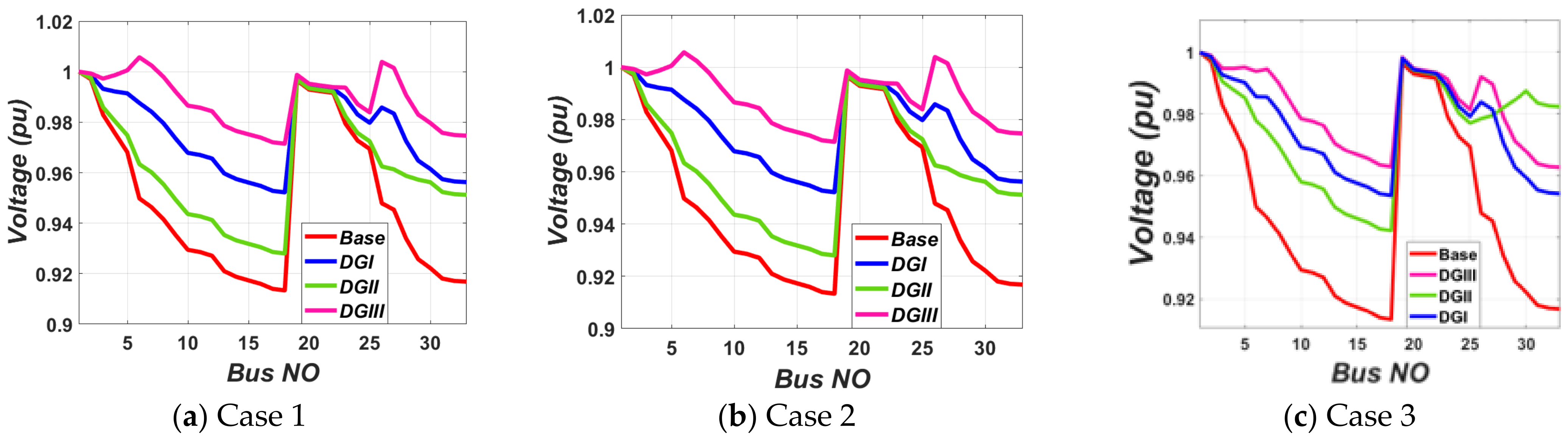
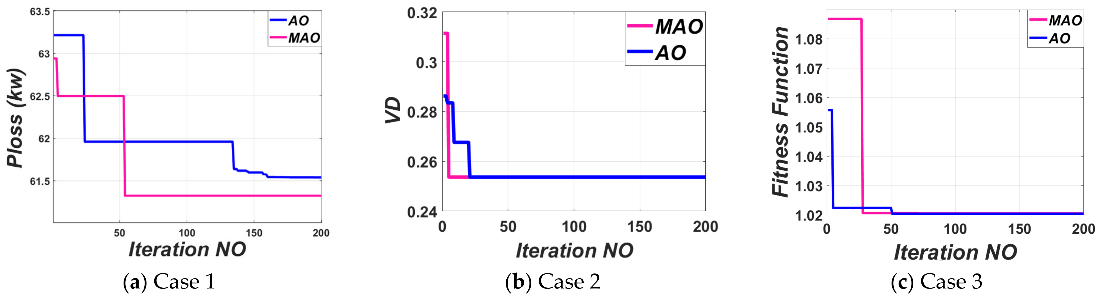
  • Scenario I: using one DG in different types for supplying various PQ capacities to optimize a certain objective function as below:
    Case 1:
    optimal DG allocation based on minimization of power losses.
    Case 2:
    optimal DG allocation based on minimization of voltage deviation.
    Case 3:
    optimal DG allocation based on loss minimization and voltage deviation reduction.
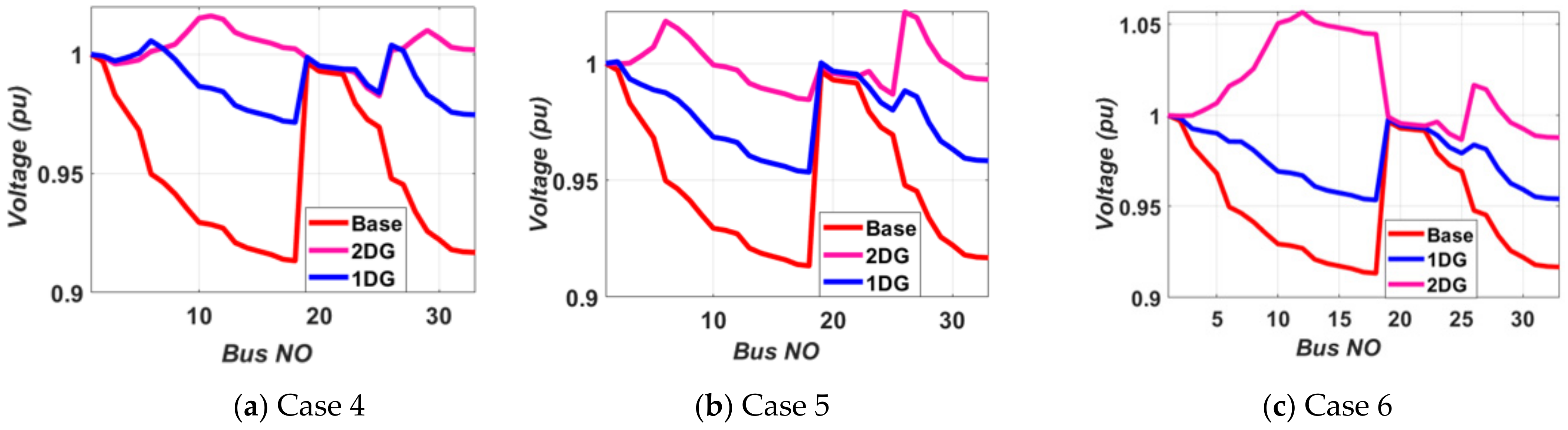
  • Scenario II: using a number of DGs for supplying various PQ capacities to optimize a certain objective function as below:
    Case 4:
    optimal DG units for minimization of power losses.
    Case 5:
    optimal DG units for minimization of voltage deviation.
    Case 6:
    optimal DG units for loss minimization and voltage deviation reduction.
In the first scenario, a single DG is used with different types at a time to minimize a candidate’s multi-objective function. Three cases are implemented, as in case 1, the power loss is minimized, whereas in case 2, it is based on voltage deviation minimization, and minimization of both real power loss and voltage deviation are considered in case 3. The optimal locations and sizes were determined via the AO and MAO and compared with conventional PSO and TIA. The set of optimal values attained by the AO and MAO are given in Table 13, Table 14 and Table 15.
Without DG installation, the power losses and the total voltage deviation were 202 kW and 1.7 pu, respectively. Table 13 illustrates that when case 1 took place by employing the proposed three DG types, the power losses were reduced by 49.1%, 29.78%, and 69.64%, respectively. Moreover, the total voltage deviation (TVD) decreased by 53%, 25.6%, and 71.5%. Similarly, from case 2, it was found that the power losses were decreased by 26%, increased by 32%, and decreased by 54.6%, whereas the TVD decreased by 78%, 68.8%, and 85%, as shown in Table 14. Finally, case 3 indicated, as shown in Table 15, that the power losses were reduced by 46.9%, 43.29%, and 48.8%. Additionally, the TVD decreased by 64.9%, 52.5%, and 53.8%.
The voltage profiles before and after enhancement are shown in Figure 15. The results emphasize that if case 1 occurred, the DG of type 2 failed to maintain the system voltage within the minimum permissible limits as illustrated in Figure 15a. Noticeably, the performance of the DG of type 3 can strongly outperform that of the other types. Under case 2, the results described in Figure 15b illustrate that the DGs of types 1 and 3 succeeded in keeping the system voltage within the permissible limits, but the remaining type failed to preserve these limits. Moreover, a DG of type 3 showed a substantial impact on the system enhancement level. When considering case 3, the results confirm that the DGs of types 1 and 3 showed a high impact on improving the system performance as clarified in Figure 15c. Noticeably, the DG of type 2 failed to maintain the system voltage within the standard limits.
The simulation results proved that considering only a single objective improves this variable at the other’s expense. Moreover, it was found that under the power loss minimization criterion, the network minimum TVD had a slight improvement and vice versa. The outcomes showed that the voltage deviation improved and power loss was reduced by applying the DG units of three types based on the three different OFs, considering both objectives are needed to obtain the best performance. The convergence curves of the AO and MAO algorithms for optimizing type 3 are presented in Figure 16. It can be of concern that the MAO converged to the steady value within a period of less than 50 iterations whereas the AO took more than 100 iterations and fell into local optimal solutions, as shown in Figure 16a. The MAO had the best performance along with lower computation time compared with the AO algorithm without trapping into a local optimal solution.
Table 16 displays the outcomes of the suggested approach for determining the best size, site, and power factor of DG units in a 33-bus system. According to this table, the suggested algorithm obtained the lowest power loss when compared to the PSO [35] and TIA [35].
In the second scenario, simultaneous optimal placement of multi-DGs was implemented for supplying various P Q capacities in the distribution networks, considering power loss lessening and voltage deviation enhancement as an objective function. Table 17 explains the results obtained for choosing the third type of DG, considering power loss reduction only, whereas Table 18 and Table 19 present the ODGA, considering voltage deviation reduction only and power loss and voltage deviation minifying together, respectively. Figure 17 shows the voltage profiles for the IEEE 33-bus system in various cases. From the aforementioned tables, it was deduced that power loss was 202 kW and the min voltage obtained was 0.9038 pu at bus 18 without DG. If a single DG was installed at bus 6, the power loss could be reduced to 69.94% and the min voltage would be 0.975 pu at bus 18, whereas placing two DGs simultaneously yielded an 81.2% reduction in power. Figure 17a depicts the voltage profile at various buses for varying numbers of DGs in the network.

4. Conclusions

In this study, a novel alternate metaheuristic approach, named the modified Aquila optimizer, was created. The performance of the developed MAO was first evaluated using 23 benchmark functions to establish its superiority over the standard Aquila optimizer. Thereafter, both the MAO and AO were used to design a multi-DG placement with the objectives of cutting losses and developing voltage profiles. Proper DG selection considerably diminishes the power loss in the system. The third type of DG that injects real and reactive power reduced the power losses by more than the first and second types of DG for the same number of DG placements. The suggested approach is efficient in terms of loss reduction and voltage enhancement. It also enhances the voltages at the nodes at the tail end.
The study performed in this work was worthwhile, but some significant issues should be emphasized. The basic principles were optimal siting and scaling of DGs in the IEEE 33-bus system; however, other parallel types of study have been conducted to enhance the results. The impacts of the number and type of DG were addressed in this paper. The DG providing varied P Q capabilities was also covered, including cases of P only, Q only, and P and Q together. Three distinct algorithms were used to compare and assess all of the findings (MAO, PSO, and TIA). The following are the visible final conclusions of the research:
(1)
The MAO gives the overall best results for the CEC benchmark functions considering solution accuracy and convergence time.
(2)
The MAO was tested on the IEEE 33-bus test system to detect its notability.
(3)
The MAO gives the optimal result for the ODGA problem in a very short time.
(4)
Placement of two DGs is the best case, demonstrating that higher DG incorporation reduces overall power losses and reinforces the voltage profile in the system.
(5)
DG delivering both real P and reactive Q power is the best-suited option for the system, indicating that DG produces the greatest outcomes while operating in an ideal power factor environment.
(6)
The proposed algorithm is preferred for obtaining the control variables (DG locations and sizes) to find the best optimal values of the fitness function.
(7)
The traditional system is restructured by optimally merging the DG in ideal locations with optimal dimensions. This makes the grid work smarter, which falls within the purview of a smart grid environment.
According to the previous discussion that illustrated the developed MAO’s superiority, it can open a wide range of future works. This includes applying the MAO to various applications such as PV parameter estimation, PI parameter tuning, management applications such as energy management and load management, conventional and smart grid applications, industry and engineering applications, other benchmark test functions, and smart home applications. It can also be extended to real-world applications dependent on binary-, discrete-, and multiple-objective optimization. Moreover, it can be mixed with other stochastic algorithms for enhancing their results of optimization problems, escaping the local minima problem, and obtaining a global solution.

Author Contributions

Conceptualization, M.H.A. and S.K.; Methodology, A.T.S. and H.B.S.; Formal analysis, M.H. and M.S.; Validation, M.H.A. and S.K.; Visualization, A.T.S. and H.B.S.; Resources, M.H. and M.S.; Writing—original draft, M.H.A., S.K. and A.T.S.; Writing—review & editing, H.B.S., M.H. and M.S. All authors have read and agreed to the published version of the manuscript.

Funding

This research received no external funding.

Institutional Review Board Statement

Not applicable.

Informed Consent Statement

Not applicable.

Data Availability Statement

Not applicable.

Conflicts of Interest

All authors declare no conflict of interest.

Nomenclature

ABCartificial bee colony
AOAquila optimizer
ALOant lion optimization
AVDIaggregate voltage deviation index
BSbacktracking search
CBcapacitor bank
CECcompetition on evolutionary computation
DGdistributed generation
DNsdistribution networks
DSdistribution system
FLCfuzzy logic control
GAgenetic algorithm
GSAgravitational search algorithm
IDSAimproved differential search algorithm
IRROimproved raven roosting optimization
IWHOimproved wild horse optimization
IWOinvasive weed optimization
LSFloss sensitivity factor
LLIline loading index
MAOmodified Aquila optimizer
MODGAmulti-objective optimal distributed generation allocation
MOmulti-objective
MOFmulti-objective function
MOPImulti-objective performance index
MOSBmulti-objective shuffled bat
MOCDEMO opposition-based chaotic differential evolution
MOPSOMO particle swarm optimization
MOHSAMO harmony search algorithm
OBLoppositional-based learning
ODGAoptimal distributed generation allocation
ODGPoptimal distributed generation problem
ORESPoptimal renewable energy source placement
PLRIpower loss reduction index
PQpower quality
PSOparticle swarm optimization
QOCSOSquasi-oppositional chaotic symbiotic organisms search
QOBLquasi-oppositional-based learning
RESrenewable energy source
SCAsine-cosine algorithm
SFLAshuffled frog-leaping algorithm
TSAtunicate swarm algorithm
TIAtrader-inspired algorithm
UPSOunified particle swarm optimization
TVDtotal voltage deviation
VDIvoltage deviation index
VPIvoltage profile index
VSIvoltage stability index
VSMvoltage stability margin
WOAwhale optimization algorithm
Symbols
B mutual susceptance
D dimension size
G mutual conductance
G 1 prey tracking motion pattern
G 2 flight slope
G K line conductance
L e v y D levy flight distribution
l b lower bound
n total system buses
N population size
P real power
P D real power demand
P G real power generated
P L real power loss
Q reactive power
Q D reactive power demand
Q G reactive power generated
Q F quality function
T maximum iteration
t   current iteration
u b upper bound
V i voltage at bus   i
V i m a x maximum voltage at bus i
V i m i n minimum voltage at bus i
x 0 opposite number
x q 0 quasi-opposite number
α AO adjustment parameter 1
δ AO adjustment parameter 2

References

  1. Mirjalili, S.; Lewis, A. The whale optimization algorithm. Adv. Eng. Softw. 2016, 95, 51–67. [Google Scholar] [CrossRef]
  2. Abualigah, L.; Yousri, D.; Elaziz, M.A.; Ewees, A.A.; Al-Qaness, M.A.; Gandomi, A.H. Aquila Optimizer: A novel meta-heuristic optimization algorithm. Comput. Ind. Eng. 2021, 157, 107250. [Google Scholar] [CrossRef]
  3. Wang, S.; Jia, H.; Abualigah, L.; Liu, Q.; Zheng, R. An Improved Hybrid Aquila Optimizer and Harris Hawks Algorithm for Solving Industrial Engineering Optimization Problems. Processes 2021, 9, 1551. [Google Scholar] [CrossRef]
  4. Salawudeen, A.T.; Mu’Azu, M.B.; Sha’Aban, Y.A.; Adedokun, A.E. A Novel Smell Agent Optimization (SAO): An extensive CEC study and engineering application. Knowl.-Based Syst. 2021, 232, 107486. [Google Scholar] [CrossRef]
  5. Alam, S.; Al-Ismail, F.S.; Salem, A.; Abido, M.A. High-Level Penetration of Renewable Energy Sources Into Grid Utility: Challenges and Solutions. IEEE Access 2020, 8, 190277–190299. [Google Scholar] [CrossRef]
  6. Duong, M.Q.; Pham, T.D.; Nguyen, T.T.; Doan, A.T.; Tran, H.V. Determination of optimal location and sizing of solar photovoltaic distribution generation units in radial distribution systems. Energies 2019, 12, 174. [Google Scholar] [CrossRef] [Green Version]
  7. Naderi, E.; Narimani, H.; Pourakbari-Kasmaei, M.; Cerna, F.V.; Marzband, M.; Lehtonen, M. State-of-the-Art of Optimal Active and Reactive Power Flow: A Comprehensive Review from Various Standpoints. Processes 2021, 9, 1319. [Google Scholar] [CrossRef]
  8. Palanisamy, R.; Muthusamy, S.K. Optimal Siting and Sizing of Multiple Distributed Generation Units in Radial Distribution System Using Ant Lion Optimization Algorithm. J. Electr. Eng. Technol. 2021, 16, 79–89. [Google Scholar] [CrossRef]
  9. Ali, M.H.; Mehanna, M.; Othman, E. Optimal planning of RDGs in electrical distribution networks using hybrid SAPSO algorithm. Int. J. Electr. Comput. Eng. (IJECE) 2020, 10, 6153–6163. [Google Scholar] [CrossRef]
  10. Ali, M.H.; Kamel, S.; Hassan, M.H.; Tostado-Véliz, M.; Zawbaa, H.M. An improved wild horse optimization algorithm for reliability based optimal DG planning of radial distribution networks. Energy Rep. 2021, 8, 582–604. [Google Scholar] [CrossRef]
  11. Agajie, T.F.; Salau, A.O.; Hailu, E.A.; Sood, M.; Jain, S. Optimal sizing and siting of distributed generators for minimization of power losses and voltage deviation. In Proceedings of the 2019 5th International Conference on Signal Processing, Computing and Control (ISPCC), Solan, India, 10–12 October 2019; pp. 292–297. [Google Scholar]
  12. Awad, A.; Abdel-Mawgoud, H.; Kamel, S.; Ibrahim, A.; Jurado, F. Developing a Hybrid Optimization Algorithm for Optimal Allocation of Renewable DGs in Distribution Network. Clean Technol. 2021, 3, 23. [Google Scholar] [CrossRef]
  13. Ali, Z.M.; Diaaeldin, I.M.; HEAbdel Aleem, S.; El-Rafei, A.; Abdelaziz, A.Y.; Jurado, F. Scenario-based network reconfiguration and renewable energy resources integration in large-scale distribution systems considering parameters uncertainty. Mathematics 2021, 9, 26. [Google Scholar] [CrossRef]
  14. Tan, Z.; Zeng, M.; Sun, L. Optimal Placement and Sizing of Distributed Generators Based on Swarm Moth Flame Optimization. Front. Energy Res. 2021, 9, 148. [Google Scholar] [CrossRef]
  15. Haider, W.; Hassan, S.J.U.; Mehdi, A.; Hussain, A.; Adjayeng, G.O.M.; Kim, C.-H. Voltage Profile Enhancement and Loss Minimization Using Optimal Placement and Sizing of Distributed Generation in Reconfigured Network. Machines 2021, 9, 20. [Google Scholar] [CrossRef]
  16. Jordehi, A.R. Optimisation of electric distribution systems: A review. Renew. Sustain. Energy Rev. 2015, 51, 1088–1100. [Google Scholar] [CrossRef]
  17. Venkatesan, C.; Kannadasan, R.; Alsharif, M.; Kim, M.-K.; Nebhen, J. A Novel Multiobjective Hybrid Technique for Siting and Sizing of Distributed Generation and Capacitor Banks in Radial Distribution Systems. Sustainability 2021, 13, 3308. [Google Scholar] [CrossRef]
  18. Prakash, P.; Khatod, D.K. Optimal sizing and siting techniques for distributed generation in distribution systems: A review. Renew. Sustain. Energy Rev. 2016, 57, 111–130. [Google Scholar] [CrossRef]
  19. Hussain, A.; Shah, S.D.A.; Arif, S.M. Heuristic optimisation-based sizing and siting of DGs for enhancing resiliency of autonomous microgrid networks. IET Smart Grid 2019, 2, 269–282. [Google Scholar] [CrossRef]
  20. Ramamoorthy, A.; Ramachandran, R. Optimal Siting and Sizing of Multiple DG Units for the Enhancement of Voltage Profile and Loss Minimization in Transmission Systems Using Nature Inspired Algorithms. Sci. World J. 2016, 2016, 1086579. [Google Scholar] [CrossRef] [PubMed] [Green Version]
  21. Prakash, D.; Lakshminarayana, C. Multiple DG placements in radial distribution system for multi objectives using Whale Optimization Algorithm. Alex. Eng. J. 2018, 57, 2797–2806. [Google Scholar] [CrossRef]
  22. Sa’Ed, J.A.; Amer, M.; Bodair, A.; Baransi, A.; Favuzza, S.; Zizzo, G. A Simplified Analytical Approach for Optimal Planning of Distributed Generation in Electrical Distribution Networks. Appl. Sci. 2019, 9, 5446. [Google Scholar] [CrossRef] [Green Version]
  23. Sharma, S.; Bhattacharjee, S.; Bhattacharya, A. Quasi-Oppositional Swine Influenza Model Based Optimization with Quarantine for optimal allocation of DG in radial distribution network. Int. J. Electr. Power Energy Syst. 2016, 74, 348–373. [Google Scholar] [CrossRef]
  24. El-Fergany, A. Multi-objective Allocation of Multi-type Distributed Generators along Distribution Networks Using Backtracking Search Algorithm and Fuzzy Expert Rules. Electr. Power Compon. Syst. 2015, 44, 252–267. [Google Scholar] [CrossRef]
  25. Prabha, D.R.; Jayabarathi, T. Optimal placement and sizing of multiple distributed generating units in distribution networks by invasive weed optimization algorithm. Ain Shams Eng. J. 2016, 7, 683–694. [Google Scholar] [CrossRef] [Green Version]
  26. Mehta, P.; Bhatt, P.; Pandya, V. Optimal selection of distributed generating units and its placement for voltage stability enhancement and energy loss minimization. Ain Shams Eng. J. 2018, 9, 187–201. [Google Scholar] [CrossRef]
  27. Gkaidatzis, P.A.; Bouhouras, A.S.; Sgouras, K.I.; Doukas, D.I.; Christoforidis, G.C.; Labridis, D.P. Efficient RES Penetration under Optimal Distributed Generation Placement Approach. Energies 2019, 12, 1250. [Google Scholar] [CrossRef] [Green Version]
  28. Yammani, C.; Maheswarapu, S.; Matam, S.K. A Multi-objective Shuffled Bat algorithm for optimal placement and sizing of multi distributed generations with different load models. Int. J. Electr. Power Energy Syst. 2016, 79, 120–131. [Google Scholar] [CrossRef]
  29. Injeti, S.K. A Pareto optimal approach for allocation of distributed generators in radial distribution systems using improved differential search algorithm. J. Electr. Syst. Inf. Technol. 2018, 5, 908–927. [Google Scholar] [CrossRef]
  30. Tang, D.; Zhao, J.; Yang, J.; Liu, Z.; Cai, Y. An Evolutionary Frog Leaping Algorithm for Global Optimization Problems and Applications. Comput. Intell. Neurosci. 2021, 2021, 8928182. [Google Scholar] [CrossRef]
  31. Shandilya, S.; Izonin, I.; Shandilya, S.K.; Singh, K.K. Mathematical modelling of bio-inspired frog leap optimization algorithm for transmission expansion planning. Math. Biosci. Eng. 2022, 19, 7232–7247. [Google Scholar] [CrossRef]
  32. Kumar, S.; Mandal, K.; Chakraborty, N. Optimal DG placement by multi-objective opposition based chaotic differential evolution for techno-economic analysis. Appl. Soft Comput. 2019, 78, 70–83. [Google Scholar] [CrossRef]
  33. Nagaballi, S.; Kale, V.S. Pareto optimality and game theory approach for optimal deployment of DG in radial distribution system to improve techno-economic benefits. Appl. Soft Comput. 2020, 92, 106234. [Google Scholar] [CrossRef]
  34. Truong, K.H.; Nallagownden, P.; Elamvazuthi, I.; Vo, D.N. A Quasi-Oppositional-Chaotic Symbiotic Organisms Search algorithm for optimal allocation of DG in radial distribution networks. Appl. Soft Comput. 2020, 88, 106067. [Google Scholar] [CrossRef]
  35. Mohamed, M.A.; El-Sehiemy, R.A.; El-Dabah, M.A. Optimal operation of electrical distribution networks including distributed generation units using trader optimization algorithm. In Proceedings of the CIRED 2021 Conference, online, 20–23 September 2021. [Google Scholar]
  36. Basetti, V.; Rangarajan, S.S.; Kumar Shiva, C.; Verma, S.; Collins, R.E.; Senjyu, T. A Quasi-Oppositional Heap-Based Optimization Technique for Power Flow Analysis by Considering Large Scale Photovoltaic Generator. Energies 2021, 14, 5382. [Google Scholar] [CrossRef]
Figure 1. Flowchart of modified Aquila optimizer.
Mathematics 10 02129 g001
Figure 2. A radial distribution feeder.
Mathematics 10 02129 g002
Figure 3. Convergence analysis of unimodal benchmark functions with D = 10.
Mathematics 10 02129 g003
Figure 4. Convergence analysis of multimodal benchmark functions with D = 10.
Mathematics 10 02129 g004
Figure 5. Convergence analysis of unimodal benchmark functions with D = 50.
Mathematics 10 02129 g005aMathematics 10 02129 g005b
Figure 6. Convergence analysis of multimodal benchmark functions with D = 50.
Mathematics 10 02129 g006aMathematics 10 02129 g006b
Figure 7. Convergence analysis of fixed-dimensional benchmark functions.
Mathematics 10 02129 g007aMathematics 10 02129 g007b
Figure 8. Independent runs of unimodal benchmark functions with D = 50.
Mathematics 10 02129 g008aMathematics 10 02129 g008b
Figure 9. Independent runs of multimodal benchmark functions with D = 50.
Mathematics 10 02129 g009aMathematics 10 02129 g009b
Figure 10. Independent runs of fixed-dimensional benchmark functions with D = 50.
Mathematics 10 02129 g010aMathematics 10 02129 g010b
Figure 11. Convergence of MAO over 50 trials for unimodal functions of 50-dimensional variables.
Mathematics 10 02129 g011
Figure 12. Convergence of MAO over 50 trials for multimodal functions of 50-dimensional variables.
Mathematics 10 02129 g012
Figure 13. Convergence of MAO over 50 trials for fixed-dimensional variables.
Mathematics 10 02129 g013aMathematics 10 02129 g013b
Figure 14. Standard IEEE 33-bus test system.
Mathematics 10 02129 g014
Figure 15. Voltage profile for IEEE 33-bus test system.
Mathematics 10 02129 g015
Figure 16. Convergence curve of the IEEE 33-bus system.
Mathematics 10 02129 g016
Figure 17. Voltage profile for IEEE 33-bus test system including multiple DGs.
Mathematics 10 02129 g017
Table 1. Applied approaches for RESP techniques.
MethodObjective FunctionApproach DiscussionTest SystemsRef.Year
ALOLessen real power lossesLSF and VSF were utilized for finding the optimal bus locations for multiple DGs. Then, the optimal size of DGs was identified using ALO algorithm by minimizing the total real power loss of the DN.IEEE 33-, 69- and 119-bus[8]2021
SA-PSOActive power loss minimizationA new hybrid SAPSO algorithm was used to determine the correct DG installation.IEEE 33-bus[9]2020
IWHOActive power loss and reliability indicesA novel IWHO algorithm was used to define the optimal DG siting and sizing.IEEE 33-, 69- and 119-bus[10]2022
MOHSATotal losses and voltage deviationFor DG allocation, total losses and TVD were employed as OF indices.Debre Markos feeder 3[11]2019
Hybrid
(TSA-SCA)
Active power loss, TVD, and VSIMulti-objective method for determining the best DG location and size.IEEE 69-bus[12]2021
MFOActive power loss, emission, and VPIDeveloping RES to maintain sustainable development.IEEE 33-bus[14]2021
MOPSOActive power loss and TVDMOPSO was utilized to determine the optimal size and location of DGs before and after reconfiguration of the radial network.IEEE 33-bus[15]2021
Hybrid
(EGWO-PSO)
Active power loss, VDI, emission, cost, and VSIMOF was used for optimal placement and sizing of DGs and CBs.IEEE 33- and 69-bus[17]2021
Hybrid
(GA-PSO)
Active power loss and voltage regulationConvert the conventional distribution systems into resilient autonomous microgrid networks by inserting optimal DGs.IEEE 33- and 69-bus[19]2019
Hybrid
(PSO-GSA)
Total losses and voltage deviationFirstly, LSF was used to determine the optimal location. Then, the optimal size of DGs was determined by PSO, GSA, and hybrid PSO-GSA algorithms.IEEE 33-bus[20]2016
WOAActive power loss, voltage profile, and operating costWOA was used to find the optimal DGs for MOF.IEEE 33- and 69-bus[21]2018
Analytical approachActive power loss minimizationA new simplified analytical approach was introduced to find the optimal choice of DGs.IEEE 12-, 33- and 69-bus[22]2019
BS-FLCTotal power losses, TVD, and VSIBacktracking search algorithms were demonstrated and marked on the DN to determine the best solution. Among the best solutions, fuzzy was a decision-maker to decide the best compromise solution among the offered Pareto optimal solutions.IEEE 33- and 94-bus[24]2016
IWOActive power loss, voltage deviation, and operating costLSF was used to determine the bus location, whereas IWO algorithm was used to find the best size.IEEE 33- and 69-bus[25]2016
AnalyticalTotal losses index, VSI, VSM, and AVDIThe choice of the correct type of DG unit and its optimal location to enhance the voltage stability and improve the voltage profile was based on the analysis for some indexes.IEEE 33- and 136-bus[26]2018
UPSOActive power loss minimizationODGP was solved by selecting the optimal size and location of RES.
UPSO was used for solving ODGP and ORESP.
IEEE 33- and 118-bus[27]2019
MOCDEActive power losses, VD, and cost.The proposed technique used logistic mapping to generate a chaotic sequence for control parameters for solving the MO problem.IEEE 33- and 69-bus[32]2019
IRROTotal losses, VPI, VSI, and LLIMOF considered to improve the technical aspects and net economical saving cost with DG units integrated on RDS. Pareto was used to make a set of the best solutions.IEEE 33- and 69-bus[33]2020
QOCSOSActive power loss, VD, and VSIQOCSOS was utilized to determine the ODGA by solving the MOF.IEEE 33-, 69- and 118-bus[34]2020
TIAActive power loss and VSITIA was employed to determine the optimal allocation of multiple types of RESs-DGs, considering MOF.IEEE 33-bus[35]2021
Table 2. Unimodal benchmark functions.
FnDescriptionDimensionRangeFmin
F1 f ( x ) = i = 1 n x i 2 10,50,100,500[−100,100]0
F2 f ( x ) = i = 0 n x i + i = 0 n x i 10,50,100,500[−10,10]0
F3 f ( x ) = i = 1 d j = 1 i x j 2 10,50,100,500[−100,100]0
F4 f ( x ) = max i x i , 1 i n 10,50,100,500[−100,100]0
F5 f ( x ) = i = 1 n 1 100 x i 2 x i + 1 2 + 1 x i 2 10,50,100,500[−30,30]0
F6 f ( x ) = i = 1 n x i + 0.5 2 10,50,100,500[−100,100]0
F7 f ( x ) = i = 0 n i x i 4 + r a n d 0 , 1 10,50,100,500[−128,128]0
Table 3. Multimodal benchmark functions.
FnDescriptionDimensionRangeFmin
F8 f ( x ) = i = 1 n x i sin x i 10,50,100,500[−500,500]−418.9829n
F9 f ( x ) = i = 1 n x i 2 10 cos 2 π x i + 10 10,50,100,500[−5.12,5.12]0
F10 f ( x ) = 20 exp 0.2 1 n i = 1 n x i 2 exp 1 n i = 1 n cos 2 π x i + 20 + e 10,50,100,500[−32,32]0
F11 f ( x ) = 1 + 1 4000 i = 1 n x i 2 i = 1 n cos x i i 10,50,100,500[−600,600]0
F12 f ( x ) = π n 10 sin π y 1 + i n 1 y i 1 2 1 + 10 sin 2 π y i + 1 + i = 1 n u x i , 10 , 100 , 4 , w h e r e , x i + 1 4 , u x i , a , k , m K x i a m i f x i > a 0 a x i K x i a m a x i 10,50,100,500[−50,50]0
F13 f ( x ) = 0.1 sin 2 3 π x 1 + i = 1 n x i 1 2 [ 1 + sin 2 3 π x i + 1 ] + x n 1 2 + sin 2 ( 2 π x n ) + i = 1 n u x i , 5 , 100 , 4 10,50,100,500[−50,50]0
Table 4. Fixed-dimensional multimodal benchmark functions.
FnDescriptionDimensionRangeFmin
F14 f ( x ) = 1 500 + j 25 i j + i 25 x i a i j 1 2[−65,65]1
F15 f ( x ) = i = 1 11 a i x 1 ( b i 2 + b i x 2 ) b i 2 + b i x 3 + x 4 2 4[−5,5]0.00030
F16 f ( x ) = 4 x 1 2 2.1 x 1 4 + 1 3 x 1 6 + x 1 x 2 4 x 2 2 + 4 x 2 4 2[−5,5]−1.0316
F17 f ( x ) = x 2 5.1 4 π 2 x 1 2 + 5 π x 1 6 2 + 10 1 1 8 π cos ( x 1 ) + 10 2[−5,5]0.398
F18 f ( x ) = 1 + ( x 1 + x 2 + 1 ) 2 ( 19 14 x 1 + 3 x 1 2 14 x 2 + 6 x 1 x 2 + 3 x 2 2 × 30 + ( 2 x 1 3 x 2 ) 2 × ( 18 32 x 1 + 12 x 1 2 + 48 x 2 36 x 1 x 2 + 27 x 2 2 ) 2[−2,2]3
F19 f ( x ) = i = 1 4 c i exp j = 1 3 a i j ( x j p i j ) 2 3[−1,2]−3.86
F20 f ( x ) = i = 1 4 c i exp j = 1 6 a i j ( x j p i j ) 2 6[0,1]−3.2
F21 f ( x ) = i = 1 5 X a i X a i T + c i 1 4[0,1]−10.1532
F22 f ( x ) = i = 1 7 X a i X a i T + c i 1 4[0,1]−10.4028
F23 f ( x ) = i = 1 10 X a i X a i T + c i 1 4[0,1]−10.5363
Table 5. Results obtained for unimodal and multimodal functions with D = 10.
Unimodal Benchmark Functions with D = 10
FnAOMAOAOMAO
BestAvgWorstSTDBestAvgWorstSTDnTITime(s)nTITime(s)AR
F16.42 × 10−751.43 × 10−626.57 × 10−619.28 × 10−625.00 × 10−1483.30 × 10−1231.47 × 10−1212.09 × 10−122230.4238100.31180.43
F22.39 × 10−372.36 × 10−326.60 × 10−311.03 × 10−311.54 × 10−737.00 × 10−631.95 × 10−613.19 × 10−62600.2963270.36850.45
F31.22 × 10−722.02 × 10−569.97 × 10−551.41 × 10−556.66 × 10−1462.05 × 10−1219.59 × 10−1201.36 × 10−120230.386660.35810.26
F41.24 × 10−383.67 × 10−271.84 × 10−252.60 × 10−262.51 × 10−726.85 × 10−623.42 × 10−604.83 × 10−61600.2912300.36300.50
F53.49 × 10−050.0016810.0129430.0028541.12 × 10−052.21 × 10−020.1737783.34 × 10−021530.35541970.38531.29
F62.89 × 10−081.08 × 10−041.20 × 10−032.31 × 10−049.88 × 10−095.05 × 10−043.60 × 10−038.34 × 10−041370.29861370.36551.00
F71.79 × 10−061.33 × 10−046.07 × 10−041.34 × 10−041.27 × 10−061.57 × 10−041.05 × 10−032.07 × 10−041570.2429160.39490.10
Multimodal Benchmark Functions with D = 10
F8−6.78 × 10+04−3.63 × 10+04−1.76 × 10+041.39 × 10+04−4.77 × 10+04−1.96 × 10+04−9.27 × 10+039.17 × 10+031370.273260320.3448750.23
F90.00 × 10+000.00 × 10+000.00 × 10+000.00 × 10+000.00 × 10+000.00 × 10+000.00 × 10+000.00 × 10+00270.270444100.3961440.37
F108.88 × 10−168.88 × 10−168.88 × 10−160.00 × 10+008.88 × 10−168.88 × 10−168.88 × 10−160.00 × 10+00640.251370260.3849630.41
F110.00 × 10+000.00 × 10+000.00 × 10+000.00 × 10+000.00 × 10+000.00 × 10+000.00 × 10+000.00 × 10+00300.283189100.4346100.33
F122.78 × 10−091.27 × 10−051.17 × 10−042.16 × 10−058.86 × 10−093.94 × 10−066.83 × 10−051.03 × 10−051910.5351821380.6428670.72
F137.86 × 10−095.23 × 10−055.73 × 10−049.84 × 10−054.70 × 10−094.82 × 10−053.70 × 10−048.10 × 10−051480.5936321520.5906241.03
Table 6. Results obtained for unimodal and multimodal functions with D = 50.
Unimodal Benchmark Functions with D = 50
FnAOMAOAOMAO
BestAvgWorstSTDBestAvgWorstSTDnTITime(s)nTITime(s)AR
F17.91 × 10−765.27 × 10−481.05 × 10−497.45 × 10−491.24 × 10−1574.34 × 10−1312.16 × 10−1293.06 × 10−130200.34605870.4465550.35
F25.83 × 10−381.84 × 10−294.30 × 10−312.61 × 10−305.38 × 10−761.29 × 10−665.70 × 10−658.09 × 10−66140.32124980.5108220.57
F31.77 × 10−708.58 × 10−523.00 × 10−531.39 × 10−522.29 × 10−1552.10 × 10−1309.62 × 10−1291.36 × 10−129120.78295020.7169660.166
F41.08 × 10−375.06 × 10−281.02 × 10−297.15 × 10−294.39 × 10−784.29 × 10−672.02 × 10−652.86 × 10−66670.314908230.4076320.34
F55.17 × 10−070.0870.01280.02092.01 × 10−050.13390.01342.78 × 10−02100.32344320.4978560.20
F64.88 × 10−082.20 × 10−033.57 × 10−045.51 × 10−045.45 × 10−074.72 × 10−040.00458.44 × 10−04110.41580520.5636040.18
F77.66 × 10−077.85 × 10−041.15 × 10−041.31 × 10−041.87 × 10−061.38 × 10−044.21 × 10−041.01 × 10−041130.5559771360.5476671.20
Multimodal Benchmark Functions with D = 50
F8−2.09 × 10+04−4.01 × 10+03−8.35 × 10+035.01 × 10+03−4.98 × 10+03−2.80 × 10+03−3.75 × 10+03483.56461720.4153641830.6741511.06
F90.00 × 10+000.00 × 10+000.00 × 10+000.00 × 10+000.00 × 10+000.00 × 10+000.00 × 10+000.00 × 10+00300.43232240.4826650.13
F108.88 × 10−168.88 × 10−168.88 × 10−160.00 × 10+008.88 × 10−168.88 × 10−168.88 × 10−160.00 × 10+00740.41667750.4553580.01
F110.00 × 10+000.00 × 10+000.00 × 10+000.00 × 10+000.00 × 10+000.00 × 10+000.00 × 10+000.00 × 10+00240.374171210.4901260.88
F126.33 × 10−082.71 × 10−061.60 × 10−053.32 × 10−065.67 × 10−085.92 × 10−065.92 × 10−051.05 × 10−0570.9907791810.87848525.86
F133.94 × 10−072.85 × 10−044.41 × 10−056.44 × 10−053.35 × 10−081.04 × 10−041.30 × 10−032.60 × 10−04101.0273841960.87852219.60
Table 7. Results obtained for unimodal and multimodal functions with D = 100.
Unimodal Benchmark Functions with D = 100
FnAOMAOAOMAO
BestAvgWorstSTDBestAvgWorstSTDnTITime(s)nTITime(s)AR
F11.25 × 10−774.93 × 10−591.07 × 10−606.98 × 10−607.17 × 10−1522.84 × 10−1285.78 × 10−1304.02 × 10−129220.28454180.5385320.36
F22.24 × 10−391.42 × 10−243.52 × 10−262.06 × 10−251.51 × 10−762.43 × 10−645.94 × 10−663.49 × 10−65110.37703120.5872540.18
F31.46 × 10−695.55 × 10−491.11 × 10−507.85 × 10−501.49 × 10−1493.07 × 10−1281.20 × 10−1295.90 × 10−129301.523620111.4339640.37
F41.46 × 10−695.55 × 10−491.11 × 10−507.85 × 10−501.54 × 10−807.08 × 10−671.55 × 10−681.00 × 10−67590.370328230.6123410.39
F51.97 × 10−040.11030.02190.03156.17 × 10−080.0916090.0150532.28 × 10−02120.3979051590.72225813.25
F62.91 × 10−067.19 × 10−041.97 × 10−041.61 × 10−041.94 × 10−061.14 × 10−028.39 × 10−041.77 × 10−031610.3574961850.6277081.15
F73.79 × 10−061.24 × 10−044.57 × 10−041.22 × 10−042.26 × 10−064.81 × 10−041.37 × 10−041.35 × 10−041760.786597261.0632930.15
Multimodal Benchmark Functions with D=100
F8−6.77 × 10+04−2.08 × 10+04−3.88 × 10+041.28 × 10+04−1.87 × 10+04−5.80 × 10+03−3.89 × 10+032.20 × 10+031770.522011960.8991670.54
F90.00 × 10+000.00 × 10+000.00 × 10+000.00 × 10+000.00 × 10+000.00 × 10+000.00 × 10+000.00 × 10+00210.54145990.5289250.43
F108.88 × 10−168.88 × 10−168.88 × 10−160.00 × 10+008.88 × 10−168.88 × 10−168.88 × 10−160.00 × 10+00600.579987240.6478320.40
F110.00 × 10+000.00 × 10+000.00 × 10+000.00 × 10+000.00 × 10+000.00 × 10+000.00 × 10+000.00 × 10+00190.56755170.6796340.37
F122.12 × 10−091.28 × 10−051.89 × 10−063.20 × 10−063.31 × 10−083.05 × 10−054.56 × 10−065.88 × 10−061981.7719361371.6692480.69
F135.44 × 10−084.67 × 10−045.33 × 10−058.09 × 10−052.05 × 10−097.29 × 10−049.69 × 10−051.59 × 10−041651.5259741511.5005340.92
Table 8. Results obtained for unimodal and multimodal functions with D = 500.
Unimodal Benchmark Functions with D = 500
FnAOMAOAOMAO
BestAvgWorstSTDBestAvgWorstSTDnTITime(s)nTITime(s)AR
F11.50 × 10−748.20 × 10−481.64 × 10−491.16 × 10−489.80 × 10−1511.25 × 10−1325.88 × 10−1318.32 × 10−132171.18828471.0926450.41
F22.69 × 10−361.27 × 10−307.35 × 10−322.12 × 10−312.17 × 10−776.73 × 10−663.17 × 10−644.48 × 10−65151.26453261.2533140.40
F33.17 × 10−685.83 × 10−441.17 × 10−458.25 × 10−458.20 × 10−1468.36 × 10−1264.02 × 10−1245.69 × 10−125339.08967297.7935910.27
F47.47 × 10−371.29 × 10−252.60 × 10−271.83 × 10−263.67 × 10−775.78 × 10−682.83 × 10−664.00 × 10−67601.323380221.4080700.37
F56.09 × 10−044.6741970.3404050.7722874.44 × 10−051.4070680.1428832.35 × 10−011361.26522171.2331980.05
F61.03 × 10−052.00 × 10−021.76 × 10−033.05 × 10−032.04 × 10−063.31 × 10−030.0259075.12 × 10−03201.3776311541.1669437.70
F71.62 × 10−064.57 × 10−049.92 × 10−059.26 × 10−051.08 × 10−061.43 × 10−044.83 × 10−041.16 × 10−04631.974413591.9663530.94
Multimodal Benchmark Functions with D = 500
F8−7.43 × 10+04−2.14 × 10+04−3.75 × 10+041.09 × 10+04−3.45 × 10+04−1.56 × 10+04−7.98 × 10+035.55 × 10+031981.43041471.4183430.04
F90.00 × 10+000.00 × 10+000.00 × 10+000.00 × 10+000.00 × 10+000.00 × 10+000.00 × 10+000.00 × 10+00251.226005101.2444860.40
F108.88 × 10−168.88 × 10168.88 × 10160.00 × 10+008.88 × 10−168.88 × 10168.88 × 10160.00 × 10+00731.217467241.2664370.33
F110.00 × 10+000.00 × 10+000.00 × 10+000.00 × 10+000.00 × 10+000.00 × 10+000.00 × 10+000.00 × 10+00241.28762471.3338750.29
F122.07 × 10−091.54 × 10−051.49 × 10−063.24 × 10−064.14 × 10−101.49 × 10−061.27 × 10−052.58 × 1061377.622310174.4253220.12
F134.12 × 10−064.14 × 10039.53 × 10041.16 × 10037.21×10−075.02 × 10−044.02 × 10−038.25 × 1004144.6027691444.36762710.28
Table 9. Results obtained for fixed-dimensional benchmark functions.
FnAOMAOAOMAO
BestAvgWorstSTDBestAvgWorstSTDnTITime(s)nTITime(s)AR
F140.9980041.41167710.763181.4674240.9981867.30193612.670511.99673771.327123561.0540498.00
F153.39 × 10−045.44 × 10−041.13 × 10−031.79 × 10−043.45 × 10−049.51 × 10−041.68 × 10−033.87 × 10−0460.38248160.3990011.00
F16−1.0316−1.0315−1.030631.77 × 10−04−1.0316−1.03083−1.028816.33 × 10−041400.3797731390.3791870.99
F170.3978870.3979350.3983036.46 × 10−050.3983490.4211340.4797311.96 × 10−021850.321453700.4070580.38
F183.000123.0381063.0074610.007343.0203733.9696858.5627641.1565931940.306667880.3760140.45
F19−3.86274−3.86073−3.854110.002118−3.86195−3.7668−3.6370.0550391780.333752750.3937990.42
F20−3.2984−3.1204−2.87350.0972−3.2097−2.7442−2.03520.24112000.3802131530.4491200.76
F21−10.1532−10.1402−9.97560.0263−10.1338−9.5941−7.94880.467430.4422471870.43595362.33
F22−10.4028−10.3868−10.32510.0186−10.4022−9.7427−7.4474627550.4015541920.46987138.40
F23−10.5358−10.5163−10.43220.0257−10.5303−9.84755−8.511320.51204730.5247731970.47969565.67
Table 10. Wilcoxon rank-sum test for D = 50.
Fnp-Valueh-Value
F10.20090
F27.0661 × 10181
F31.3695 × 10131
F47.0661 × 10181
F55.1090 × 10061
F62.8118 × 10081
F70.83880
F81.9072 × 10161
F120.51470
F130.11520
F141.1485 × 10121
F151.5445 × 10101
F163.2423 × 10041
F171.0754 × 10171
F181.0703 × 10161
F197.4858 × 10161
F202.5415 × 10161
F214.2058 × 10171
F225.3319 × 10161
F233.5254 × 10171
Table 11. Various DG types.
DG Type P Q Example
I+0Fuel cells and photovoltaic devices
II0+Capacitors
III++Synchronous generators and wind turbines
Note:(+) produces(−) absorbs
Table 12. The algorithm parameters and operative restrictions.
ParametersValue
Number of population30
Maximum iteration numbers100
α 0.2
δ 0.13
Base MVA100 MVA
Base kV12.66 kV
Node system voltage constraints 0.95   pu V i 1.05 pu
DG’s power generation constraints 0   MW P D G 3   MW
Table 13. Case 1: optimal DG allocation based on loss minimization.
DG TypeAOMAO
LocationSize
KW KVAR
PlossVDLocationSize
KW KVAR
PlossVD
Base case---201.901.6961---201.901.6961
DG I62588.6-102.790.792962608.1-102.790.786
DG II30-1311.9141.841.261030-1310.3141.841.2616
DG III624651847.661.5370.479162515.91745.361.3230.4833
Table 14. Case 2: optimal DG allocation based on voltage deviation.
DG TypeAOMAO
LocationDG Size
KW KVAR
PlossVDLocationSize
KW KVAR
PlossVD
Base case---201.901.6961---201.901.6961
DG I93000-149.550.371793000-149.550.3717
DG II10-2869.2266.890.529210-2894.19269.50.529
DG III263000300091.6850.2537263000300091.6850.2537
Table 15. Case 3: optimal DG allocation based on loss minimization and voltage deviation.
DG TypeAOMAO
LocationSize
KW
KVAR
PlossVDLocationSize
KW
KVAR
PlossVD
Base case---201.901.6961---201.901.6961
DG I73000-107.260.59573000-107.260.595
DG II30-1876.6115.260.80530-1832.2114.550.825
DG III72430.41685.0103.410.80172479.7130.20103.370.783
Table 16. The compared results of different algorithms in the IEEE 33-bus test system.
DG TypeComparisonMAOAOPSO TIA
DG ILocation666 6
SizeKW2608.12588.62588 2590
KVAR0000
Ploss102.79102.79111 111
VD0.7860.7929- -
DG IILocation30303030
SizeKW0000
KVAR1310.31311.91257 1260
Ploss141.84141.84151 151
VD1.26161.2610--
DG IIILocation6666
SizeKW2515.9246527002560
KVAR1745.31847.61307.71920
Ploss61.32361.53771 68
VD0.48330.4791- -
Table 17. Case 4: optimal DG III allocation based on loss minimization.
DG UnitsLocationDG Size
KW KVAR
PlossVD
1 DG62515.91745.361.3230.4833
2 DG111117.1851.138.10.1985
291213.91145.2
Table 18. Case 5: optimal DG III allocation based on voltage deviation.
DG UnitsLocationDG Size
KW KVAR
PlossVD
1 DG263000300091.6850.2537
2 DG231536.821032.2109.26370.2442
26609.009270.12
Table 19. Case 6: optimal DG III allocation based on loss minimization and voltage deviation.
DG UnitsLocationDG Size
KW KVAR
PlossVD
1 DG72430.41685.0103.410.801
2 DG122030.71218.2107.77150.6781
261391.0971.04
Publisher’s Note: MDPI stays neutral with regard to jurisdictional claims in published maps and institutional affiliations.

