1. Introduction
With the devastating effects of climate change across the globe, global warming is no longer merely news, but a core existential threat to humans [
1,
2]. Modern manufacturing organizations realize sustainability as an essential concept to confront climate change. Therefore, modern design engineers require new ideas to develop lightweight environment-friendly products. Since the early 1990s, lightweight designs have been extensively studied for enhancing energy efficiency, and topology optimization has been considered one of the most promising means to obtain lightweight structures [
3,
4]. Recently, topology optimization has been adopted in both academia and industry to achieve lightweight components while taking into account the overall performance such as cost, safety, and environmental friendliness [
5,
6,
7]. For instance, topology optimization techniques have been implemented in the automobile and aerospace industries to increase system sustainability and material efficiency, while reducing emissions and environmental concerns [
8,
9]. Thus, topological optimization provides a reliable and effective method for optimizing structural components and minimizing the global warming potential (GWP) [
1].
A shredding system is a mechanical component primarily used to reduce the volume of a given material. It is widely used for shredding paper, plastics, tires, wood, metals, and waste materials, including medical, agricultural, municipal, and industrial waste. Incineration has been a commonly used medical waste treatment technology due to its ability to continuously process a large volume with exceptional volume reduction. However, it possesses serious health and environmental risks; therefore, it is recommended to use a sterilization-based shredding system for the treatment of medical waste.
Figure 1 shows the sterilization-based shredding system used in this study. The use of such technology is an absolute necessity, especially after the pandemic, and an optimum design strategy is an area of interest for modern design engineers. It has been observed that, usually, engineers tend to overdesign the shredding system and select superior materials to ensure normal operation. However, this raises the overall weight of the shredding system and indirectly increases production and operational expenses. Therefore, the development of a lightweight blade is important for reducing the production cost, operational cost, and environmental impact and improving the overall performance of the system throughout its life cycle.
Although various optimization approaches have been adopted by researchers to obtain optimal geometry of a structural component to reduce system weight and power consumption [
10,
11,
12,
13], the literature available on the design aspect of the shredder system is limited and only discusses the static and modal analysis [
14,
15,
16,
17,
18,
19]. Various structural topology optimization methods have been adopted by researchers to improve the material distribution of engineering structures [
20,
21,
22,
23]. While some researchers have used internal microstructure-based material optimization methods and proposed various microstructures to improve material efficiency [
24,
25,
26,
27,
28]. However, to the author’s best knowledge, there is no study found in the literature that has focused on implementing any such methodology for the optimization of any shredding system. Therefore, the current study focuses on increasing the material efficiency of the shredder blade through topology optimization. Although microstructure-based methods have proven to significantly improve material efficiency, such methods are recommended for geometries manufactured using additive manufacturing processes. In general, the blades and cutters are manufactured using subtractive manufacturing processes, and due to high operational uncertainties, topology optimization is preferred over microstructure optimization for weight optimization of the shredder blade [
29]. The current research also evaluates the effect of topology optimization on the fatigue life of the blade. Therefore, fatigue failure is also considered in this study because it is an important design consideration that ensures the durability of a mechanical structure. Recently, FE-SAFE is increasingly being used to estimate the fatigue life of mechanical components utilizing the stress distribution obtained from FEA software such as ABAQUS and ANSYS [
30,
31,
32,
33]. Thus, in this study, topological optimization was used to optimize the blade geometry and a traditional FE-SAFE-based approach was utilized to estimate the fatigue life of the shredder blade.
In the proposed framework, a topology optimization-based design methodology that involves the development of a parametric 3D shredder blade model using CAD software is presented to improve the design step of the medical shredder blade and analyze its effect on fatigue life. The 3D model was converted to the finite element model using ABAQUS software and solved for von Mises stress and maximum displacement. The estimated fatigue life was evaluated using the FE-SAFE software, while topology optimization was performed within the ABAQUS optimization module at various volume constraints using strain energy as an optimization function. Multiple iterations were performed until convergence on the optimal volume constraint to obtain the optimal blade geometry. The optimized design was reconverted to the 3D model for static analysis and imported to the FE-SAFE for fatigue life prediction. The proposed method was validated by comparing the numerical results of weight, stress, displacement, and fatigue life of nominal and optimal designs of the shredder blade. The design parameters were evaluated at each volume constraint, and the optimal volume constraint was further adopted to determine fatigue life. Thus, the developed optimization framework is efficient and easy to implement. Therefore, it can be adopted to improve the material efficiency of any shredding system and can even be adopted for other mechanical systems to cope with the challenge of producing sustainable components while maintaining structural integrity.
Above, we have discussed the need and scope of the current work while the following sections are arranged as follows.
Section 2 explains the complete problem formulation and research methodology, including the force calculation, setting up of the FE model, fatigue analysis, and geometric optimization. The results of static analysis, topology optimization, and fatigue life prediction are presented and discussed in
Section 3. For each analysis, a comparison has been made in this section comparing the characteristics of nominal and optimal blade geometry. The results in terms of weight-saving are presented and discussed at the end of this section, along with the prospect of the current research. Finally, the conclusion of the research is stated in the last section.
2. Problem Formulation and Research Methodology
The complete problem formulation and the proposed research methodology have been discussed in this section. The first step in the problem formulation is developing the 3D model of the blade geometry, which is accomplished through reverse engineering and then developing its FE model. The material characteristics and the boundary conditions are the essential features to define in the FE model. The blade material properties and characteristics are discussed in
Section 2.1, while the force calculations to define boundary conditions are discussed in
Section 2.2. The next three sub-sections provide an in-depth overview of the finite element analysis, high cycle fatigue analysis, and geometric optimization employed in the proposed framework.
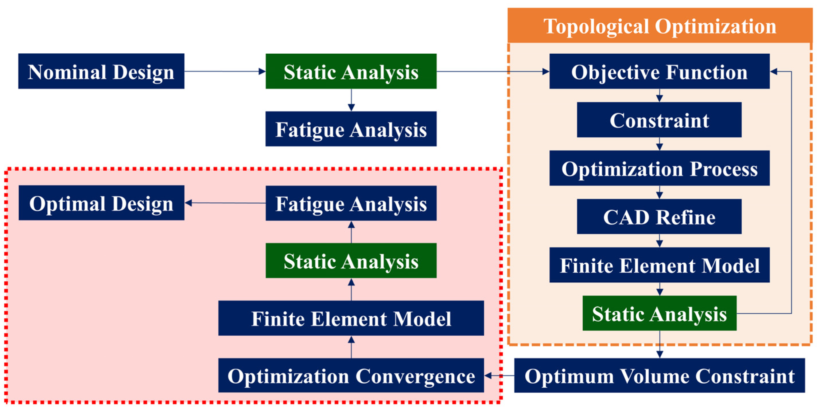
Various computer-aided engineering (CAE) tools were used for the optimization of the shredder blade from a nominal design defined as a valid structure to be used as a starting point.
Figure 2 shows the complete flow of the research methodology. The structural FEA was performed on the nominal design to check for the static stress characteristics, which include von Mises stress and maximum displacement. The results were then integrated with the ABAQUS topology optimization module, where the compliance minimization topology optimization problem is defined. This has been achieved via setting the strain energy as the optimization function and applying the volume constraints. The topology optimization was performed on various volume constraints to determine the optimum volume constraints for the current model geometry. The optimum volume constrained is identified based on four design parameters, including strain energy, mass, von Mises stress, and displacement. Multiple iterations were then performed on the optimum volume constraint to observe the design changes, and the optimization process was repeated until convergence to look for the global optimum solution. The derived geometry after geometric repairing is reanalyzed for structural characteristics to determine structural integrity. Then, the fatigue life estimation was performed by integrating the ABAQUS results with the FE-SAFE module. The estimated life of the blade was predicted using the normal stress approach based on the Morrow numerical model and compared for both nominal and optimum geometries.
In this study, we used VC for the “volume constraint” of optimized models with a suffix indicating the percentage volume fraction of the nominal geometry set as a constraint during optimization.
Table 1 shows the complete nomenclature of the volume constraints.
2.1. Material Properties
The method is initialized by assigning the material to the design domain. The majority of the components of a shredding system are manufactured from steel alloys. The blade material was selected as Hardox-550 due to its increased strength and high abrasion resistance. It also provides a reduced cost to performance ratio compared to other steel alloys with applications in shredders, cutters, and hammers [
34].
Table 2 shows the mechanical properties of Hardox-550 adopted as H-550 in this study [
34,
35].
2.2. System Geometry and Forces
The shredding system is arranged in such a way that the gears are mounted at one end of the cutting shaft, and the motor is connected to the other end. Since the CAD models for the components of the shredding system were not available, the drawings provided by the Samyoung Plant Co., Ltd, South Korea were converted to the CAD models using Solidworks. The CAD model of each component was individually exported and then assembled to check the overall contacts and motion of the system.
Figure 3 shows the complete assembled shredding system after successfully animating the motion mechanism.
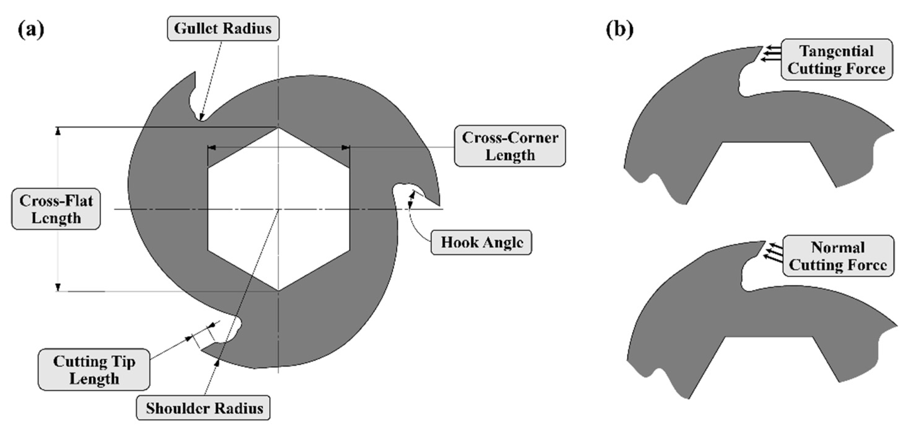
In the shredding system, the cutting shaft is powered by the motor, and a reducer (gear ratio 21:1) is used to increase the torque of the driven shaft. The transmitted torque is further increased for the driven shaft using the gears mounted at the other end. The increased torque is important for improving the cutting efficiency as it provides a higher cutting force. The cutting force mainly depends on the required power and determines the sizing of the entire system. In this study, the cutting force is determined by the power transmitted from the motor to the blades through the rotary motion of the shafts supported by gears and bearings. To overcome the disadvantage of stress concentrations introduced due to the notch effect in a keyed joint with inconsistent loading, the hexagonal shaft was used instead of the cylindrical shaft. The shredder blade geometry can be defined based on the number of cutting hooks, cutting tip length, hook angle, gullet radius, shoulder radius, and across flat and across corner lengths of the inner hexagon.
Figure 4a shows the complete geometric nomenclature of the blade profile. Furthermore, other parameters such as motor power, reducer ratio, gear ratio, gear pitch diameter, and blade diameter must be established to completely define the overall system mechanics. The calculation of the cutting force is determined by the aforementioned parameters through the fundamental machine design expressions presented in Equation (1) below:
where
Ft1 is the tangential cutting force at the driver shaft,
Ft2 is the tangential cutting force of the driven shaft,
P is the motor power,
Gr is the gear ratio of the reducer,
N is the rpm at the motor shaft,
Gg is the gear ratio of the gears, and
R is the shoulder radius of the blade. The direction of the cutting forces with respect to the blade tip is shown in
Figure 4b.
Table 3 shows the summary of the cutting forces evaluated for the shredder blade. Since the tangential forces are not perpendicular to the cutting surface of the hook, it is important to transform the tangential cutting force into normal cutting force by transforming the tangential cutting force
Ft1 and
Ft2 of the driver and driven shaft, respectively, to normal cutting force
Fn1 and
Fn2 of the driver and driven shaft, using the hook angle. The maximum actual force exerted on the blade edge becomes 38.86 kN for the driven shaft (
Fn2), which will be used in further studies for design and optimization purposes. For simplicity, this design cutting force will be termed as
Fc in the rest of the study.
2.3. Finite Element Analysis
The finite element analysis (FEA) is a mathematical tool applied to understand and compute the impacts of real-world challenges on a component or assembly level using mathematical models. The system under investigation is put together into a finite domain, which approximates the function capabilities in terms of nodal values. A discretized finite part domain with uncertain nodal values is created from a persistent physical system domain. Static analysis is of prime importance for relative examination since it is simple and fast compared to dynamic analysis. As a result, considering time constraints and computational cost, static analysis is preferred to dynamic analysis.
The CAD model used to perform the FEA of the shredder blade is created in the Solidworks modeling software and then imported into the ABAQUS for static structural analysis. Due to simple blade geometry, 8-node linear brick (C3D8R) elements are used as they are recommended for most engineering problems. These elements provide hexahedral mesh, which uses fewer elements as compared to the tetrahedral elements, therefore, generating a less computationally intensive FE model and saving memory and computational time. To justify the mesh independence, a mesh convergence study is performed until the FEA model converges on a solution. The previously determined cutting force was employed as the boundary condition on the cutting edge while all DOFs of the inner hexagonal hole were constrained. The results of FEA were used within ABAQUS to perform topology optimization and exported to FE-SAFE for fatigue analysis.
2.4. High Cycle Fatigue Analysis
The shredding system experiences fatigue due to repeated cyclic loading, which can lead to the formation of cracks at the cutting edges of the blade. These cracks may also initiate due to the fluctuating loads while shredding various types of materials included in the medical waste. Therefore, fatigue life prediction was made for: (1) the nominal blade design and (2) the optimum blade design using the FE-SAFE fatigue life analysis software [
36]. The fatigue life of both designs was then compared to obtain the most appropriate geometry for the fatigue loading.
The state-of-the-art approaches to predicting the fatigue life of a mechanical system are classified into two discrete methods: the safe-life method and the damage tolerant method [
37,
38,
39]. The safe-life method predicts the total number of load cycles of a mechanical component before the failure using the magnitude of effective stress and produces a Wöhler’s plot (SN-plot), while the damage tolerant method predicts the evolution of a pre-existing flaw from an initial size to a critical size [
38,
40,
41]. In this study, the stress-life approach was used for the shredding system since we are interested in establishing an SN-plot of the blade. The stress-life approach is also suitable for simulating high-cycle fatigue (HCF) where applied stresses are in the elastic range, while the strain-life approach is suitable for low cycle fatigue (LCF) where plastic deformation is of prime consideration and fatigue life is less than 10
3 cycles [
42,
43,
44].
FE-SAFE environment provides strong durability analysis capabilities with an excessive range of fatigue algorithms for different materials, loading conditions, and analysis approaches (stress-life or strain-life). The stress-life analysis includes: (1) normal stress, (2) stress-based Brown–Miller, (3) von Mises, (4) uniaxial stress, and (5) a variety of structural stress methods for welded joints [
36]. Uniaxial stresses rarely occur in practical systems; therefore, only the first three types of algorithms can be used for shredder blade analysis. The stress-based Brown–Miller approach requires plasticity correction data which is beyond the scope of this study and the von Mises approach requires the von Mises stress as the damage parameter while the ABAQUS’ static analysis ODB file provides the stress ranges. Therefore, the normal stress approach is used within the FE-SAFE module for fatigue life assessment of the shredder blade. The normal stress approach involves maximum principal stresses which are present in the static analysis output file and can be directly imported in FE-SAFE. This is a multi-axial fatigue life algorithm that evaluates the fatigue lives at eighteen planes perpendicular to the surface with 10 degrees increment. The principal stresses on each plane are used to evaluate the time-dependent history of stresses normal to the plane. The cycles are then extracted and normalized for mean stresses, and fatigue life is calculated, which can be plotted as an S-N curve. Various experimental relationships have been established in the past to represent the mean stress effect in mechanical systems. However, Marin’s general relation in Equation (2) summarizes all the proposed formulations [
45].
where
σA is the amplitude of the altering stress,
σM is the mean stress,
σA0 is the fatigue limit corresponding to zero-mean stress,
σUTS is the ultimate tensile strength of the material, while
f,
n, and
m are constants defined in the literature by Goodman, Gerber, Walker, Soderberg, and Morrow based on different types of materials and loading conditions [
46,
47]. The Morrow model is used for the fatigue analysis of the shredding system as it is known to provide better results for steel compared to other models [
48,
49]. The Morrow model is obtained by enforcing
f =
σUTS/
σF and
n =
m = 1 in the above Marin’s equations and is written as Equation (3) [
46]:
where
σF is the fatigue strength coefficient.
2.5. Geometric Optimization
The objective of geometric optimization is to discover areas that can be removed from the design domain to reduce weight while maintaining the overall performance of the system. Topology optimization was used to determine the best structural material arrangement of the shredder blade. The conventional topological optimization approach uses the FEM to examine the performance of the structure under the application of boundary conditions. The optimization process is then applied to perceive the optimal distribution of the material and void areas within the design domain under strength, stiffness, or volume constraints [
50].
In ABAQUS, the topology optimization module provides general topology optimization and stiffness-based topology optimization methodologies for configuring a topology optimization task. For the current case, we are interested in the weight reduction of the shredder blade while maintaining its strength and stiffness. This can be achieved through the stiffness-based topology optimization approach where strain energy is selected as the objective function and a volume constraint is applied to improve material efficiency. Such an optimization problem is also referred to as a compliance minimization topology optimization problem, which is confronted in this study with volume constraints. The following Equations (4)–(7) show the mathematical form of the current topology optimization problem [
51]:
where
C is the compliance taken as the objective function,
X is the vector of design variables indicating relative densities of the elements,
xe is the eth design variable,
F is the global force vector,
U is the global displacement vector,
K is the global stiffness matrix of the structure,
N is the total number of elements within the defined discrete domain,
V is the total volume of the design domain,
ve is the volume of the eth element, and
V* is the enforced value of the volume constraint.
3. Results and Discussion
The results of the proposed framework for static analysis, topology optimization, and fatigue life estimation are presented and discussed in this section.
3.1. Static Analysis
The nominal geometry does not assume the original shredder blade geometry. The design domain developed in Solidworks was imported to ABAQUS, and H-550 material properties including density, elastic modulus, and Poisson’s ratio were defined and assigned to the blade model. The section attributes were then assigned to the model and assembly was performed to implement the boundary conditions. The cutting force F
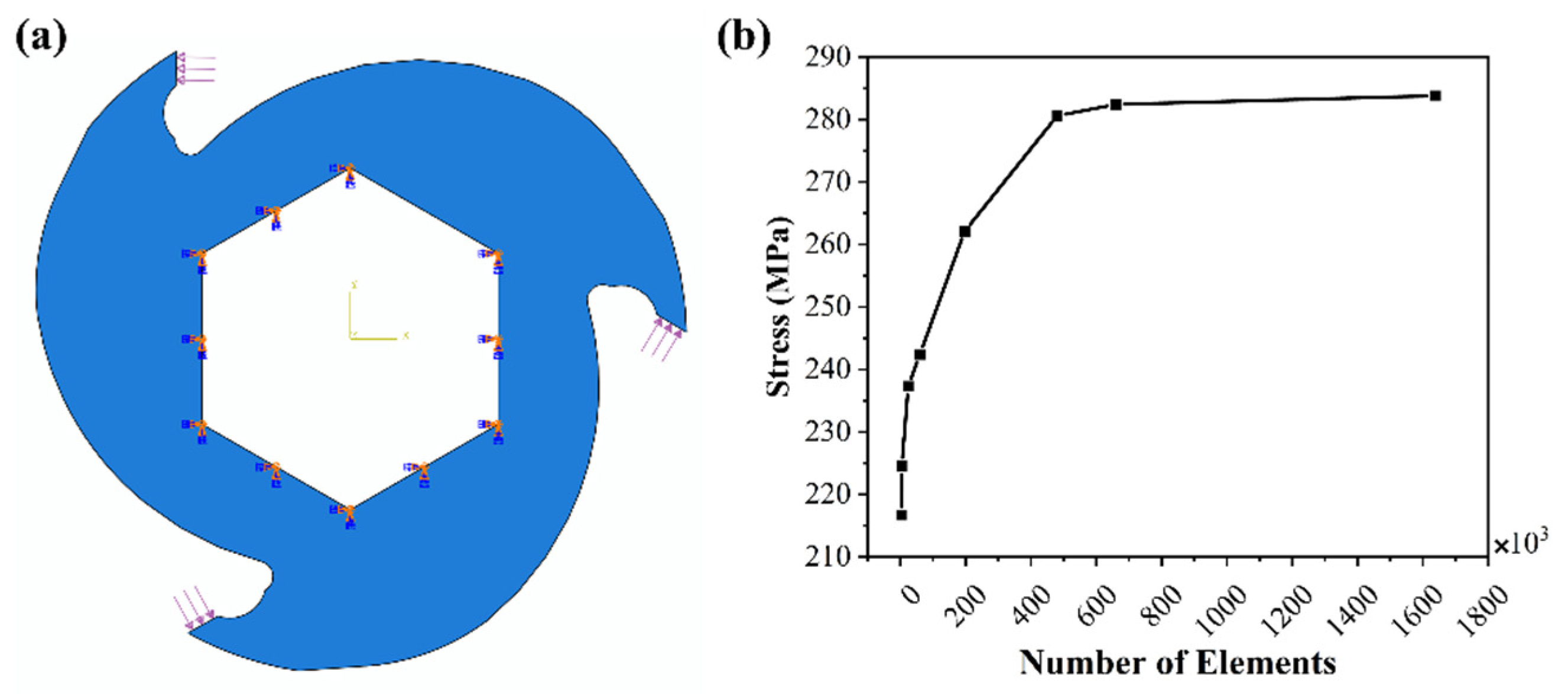
c was distributed across the cutting edge of the blade and the inner hexagonal surfaces of the blade were fixed in all degrees of freedom (DOF) to restrict the motion of the shredder blade. The implementation of these boundary conditions on the FE model is shown in
Figure 5a, where the solid region represents the design domain. Afterward, the FE model was meshed and submitted for static structural analysis in the ABAQUS solver to compute stress characteristics. A mesh convergence study was performed, and von Mises stress and maximum displacement of the blade were collected from the ABAQUS results.
The design domain was discretized with variable mesh density to assess the effect of meshing. Generally, a high mesh density provides better accuracy of the solution. However, increased mesh density significantly increases the computational time. Therefore, it is important to adequately increase the mesh density by gradually changing the mesh size from coarse to fine till mesh independence is observed in the results. Based on the mesh sizes, the number of elements in the model increased from 3905 to 1,637,509 at different mesh sizes and plotted against the von Mises stress in
Figure 5b. It can be observed that the results start converging when the number of elements is 480,375. The relative difference in the von Mises stress between 197,316 and 480,375 elements is 7.06%, while it has reduced to only 0.64% for the next point. Therefore, this point is considered the convergence point since the relative difference in computational results is less than 5% [
52]. The stress and displacement produced in the blade at the convergence point are 280.6 MPa and 0.1821 mm, respectively.
Figure 6 shows the maximum stress and displacement elements in the blade model. The topology optimization and the fatigue analysis are performed at the identical mesh density.
3.2. Topology Optimization
The main objective of topology optimization is to minimize strain energy with an expected outcome of efficient material distribution while keeping constant blade thickness due to the set number of blades across the shaft. Topology optimization begins with the nominal design domain generated in the static analysis which includes distributed load on the cutting edge and fixed constraints on all the inner surfaces. Practically, only one cutting hook is performing the shredding operation at a time, resulting in a contact ratio of one. However, all blades were assigned the same loading condition to obtain smooth symmetric geometry of the blade. To obtain the optimal volume constraint for the blade geometry, the optimization process was performed by selecting strain energy as the objective function and the volume constraint was varied from 95% to 60% of the nominal blade volume with a decrement of 5%. A predetermined default limit of 50 design cycles was selected as the convergence threshold for strain energy and volume; however, the optimization process terminated below the selected threshold for all the cases. A decrease in the number of design cycles might result in undesirable optimization consequences such as changing the optimization speed or creating different optimal configurations in the solution; however, the resultant structures have the same strain energy. The general optimization settings were configured to constrain the nodes at the cutting edge to maintain the shape of the hook, and material removal does not undertake in the prescribed cutting area. Such constrained optimization stabilizes the cutting region and often reduces the number of required design cycles without affecting the cutting performance.
At this stage, the volume fraction to be removed from the nominal design during the first iteration is chosen. In the first iteration, the ABAQUS topology optimization module reduces 5% of the volume of the design domain by default. In certain circumstances, raising this beginning value may speed up the optimization without affecting the solution, particularly for models with extensive zones of relatively low stress as in the case of shredder blades. However, if the initial value is too high, the ABAQUS topology optimization module may delete a large number of elements in the first iteration, resulting in either the failure of the optimization or generating a coarse structure. Therefore, it is important to optimize at multiple volume constraints and obtain optimal volume constraints. In the case of a shredder blade, the optimal volume constraint is established based on numerous design parameters such as strain energy, the mass of the blade, von Mises stress, and maximum displacement. These parameters are obtained during the iterative optimization process, a complete single iteration process is shown in
Figure 7. The strain energy is obtained for the topological solution while the von Mises stress, maximum displacement, and mass of the blade were evaluated in the structural validation step described in the section below.
While attempting to meet the optimization objective and constraint, the ABAQUS topology optimization module distributes the given mass within the design domain predefined in the static analysis. The structure contains both solid (hard) and void (soft) elements at the end of the optimization process. The void elements have a minor impact on the structure’s stiffness; therefore, they are removed until the convergence is established between the strain energy and the volume constraint. Furthermore, the ABAQUS topology optimization keeps soft elements that prohibit hard elements from moving about one another, such as hard elements with a shared edge but no common face.
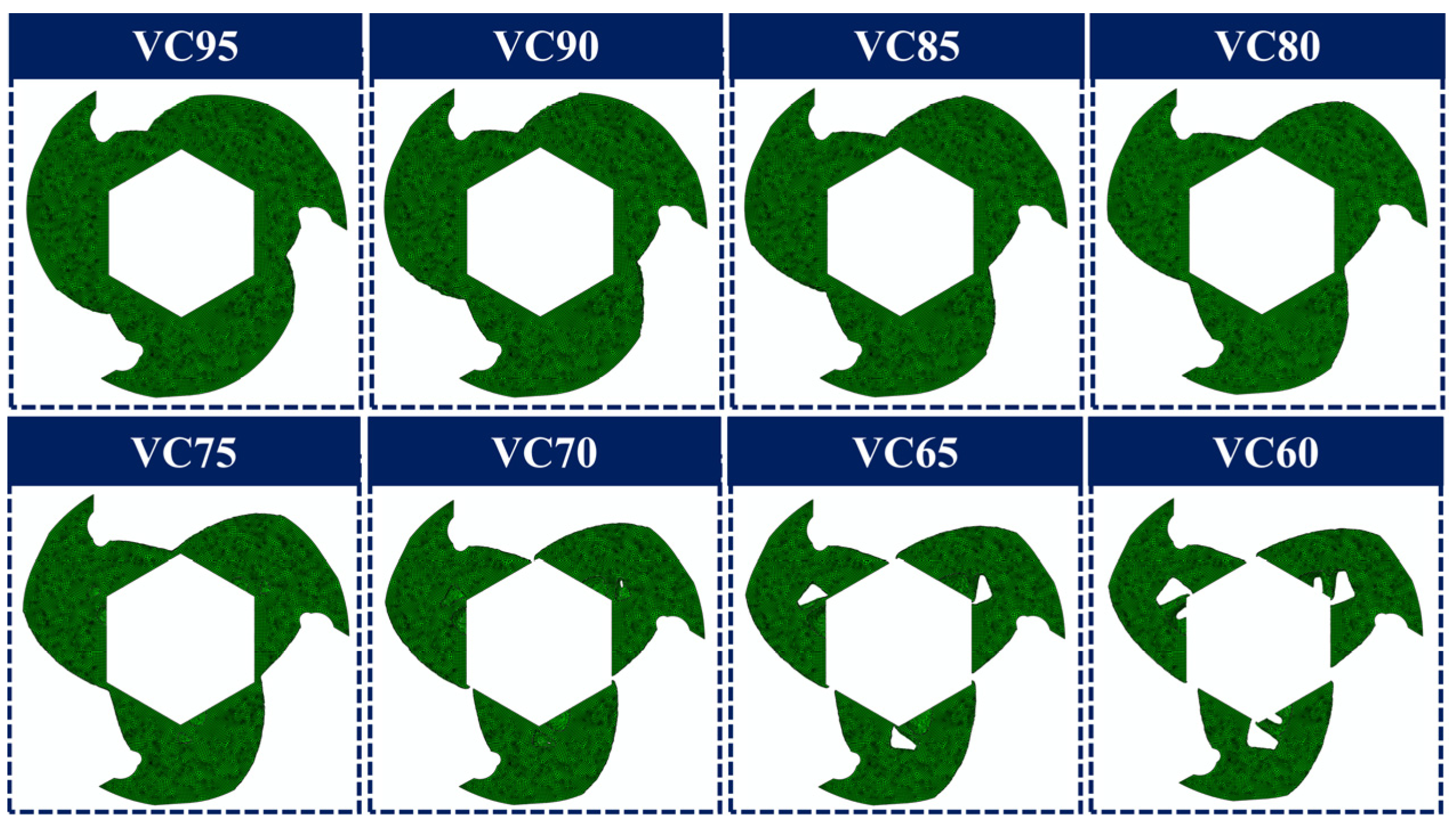
The new material distributions are obtained from the optimization process altering the density and stiffness of the elements within the design domain while maintaining the optimization restrictions of minimum volume as shown in
Figure 8. The material removal was observed only at the outer surfaces of the blade for VC95, VC90, VC85, and VC80. Among these, the maximum material removal was observed for VC80. For the VC75, VC70, VC65, and VC60 geometries, the material removal was also observed in the interior regions of the geometry creating holes. Maximum material removal is observed for the VC60 optimal design. However, an island of hard elements is also formed in the optimized VC70, VC65, and VC60 geometries, which makes them unsuitable for practical application. Still, it has been assumed during the optimization process that these models could produce actual realizable geometry after geometric repairing considering the manufacturing constraint. Thus, they have been geometrically repaired and checked against the design parameters, including strain energy, mass, von Mises, and displacement, along with the models obtained at other VCs.
3.3. Geometry Repairing and Structural Validation
The resulting topologies from the optimization process produce complex contours on the surface which are pitted, notched, and highly jagged (see
Figure 9a). As a result, repairs must be performed before further processing of the optimized geometry. The model is exported to Solidworks and traced to smooth and easily manufacturable form because the actual shredder blade must be smooth and easy to manufacture. During smoothening, the possible weak points such as the notches shown in
Figure 9a were removed using the geometric guides of the optimized geometries. The repairing process eases the manufacturing process and eliminates the error that may affect the fabrication of mechanical components [
29,
53,
54]. The surface must also be smoothed to avoid the notching effect and uniform distribution of the material.
Figure 9b shows the repaired blade geometry which was used to reperform the structural analysis to validate the structural feasibility of the optimized geometry.
Figure 9c shows the von Mises stress for the repaired CAD model of VC80. The process was repeated for the optimized geometries of all volume constraints.
Although the optimized design with holes provides a significant reduction in mass, they cause a higher displacement of the cutting. Such geometries are also difficult to manufacture and are not feasible for the shredding system. Therefore, the optimized geometries with a volume constraint of 75% and less are unsuitable for the shredder blade.
The repaired blade CAD models for all volume constraints were reanalyzed to determine their structural stability. The static analysis characteristics of von Mises stress and maximum displacement were evaluated with the same boundary conditions.
Figure 10 shows the strain energy, mass, von Mises stress, and maximum displacement for the topologically optimized geometries with various volume constraints.
Figure 10a shows the effect of volume constraint on the strain energy and mass of the blade. The high VC models provided greater stiffness values because they possess almost identical strain energies. The maximum strain energy was achieved for the VC95 model; however, the difference is negligible until the VC80 model. The strain energy increased to higher values for the remaining VCs and maximum strain energy is noted for the VC60 model. A higher mass reduction was observed as the VC is reduced due to the excessive material removal. However, the holes that started to form for VC75 were filled during the model repairing, hence increasing the mass. For all other models, the repair was performed only on the outer surface of the blade, and stress analysis was reperformed.
Figure 10b shows the summary of the results of the static analysis in terms of von Mises stress and maximum displacement at each volume constrained. The von Mises stress initially decreased with reduction in the VC and was minimum for the VC80. A maximum reduction of 6 MPa was observed for VC80 compared to the nominal design; however, the von Mises stress increased due to the formation of complex geometry below VC80. The displacement of the cutting edge also increased with a decrease in VC. The 0.56% increase is observed till VC75 which is insignificant but as the geometric complexity increases, there is a remarkable increase in the displacement. In conclusion, it was observed that the VC80 provides optimum results for most of the design parameters where von Mises stress has the maximum reduction of 6 MPa and mass reduction of 13.3% is achieved as compared to the nominal design. The highest stress concentration of 275 MPa is observed near the cutting hook of the blade and maximum displacement is produced at the cutting edge according to the FEA results. The yield stress value for the shredder blade material is 1400 MPa indicating a safety factor of approximately five. As a result of the first optimization iteration procedure, the VC80 model was demonstrated as the optimal volume constraint for the shredder blade geometry, thus it will be used for the further optimization process.
3.4. Design Iterations for Optimal Geometry
The geometry obtained at the optimal VC in the first iteration was further optimized at the same 80% volume constraint. Multiple iterations were performed until the converged results were obtained. This convergence in the iteration is again based on all the design parameters, including strain energy, mass, von Mises, and displacement.
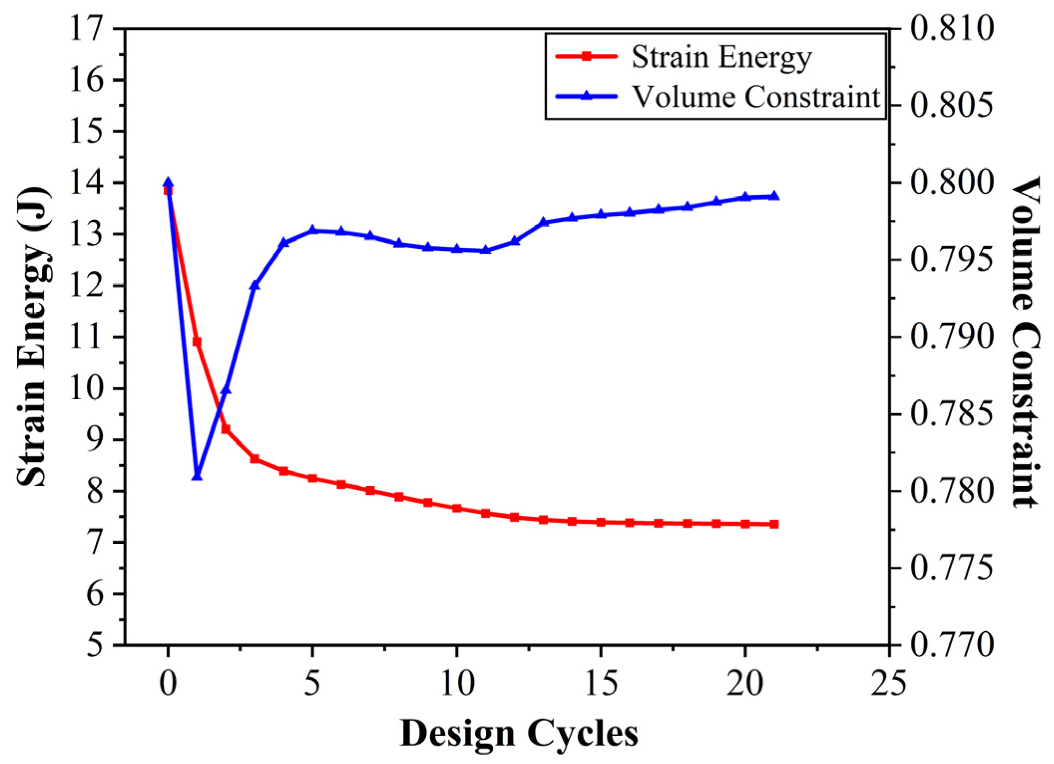
Figure 11 shows the evolution of blade topologies in each iteration step. At the end of each iteration step, the obtained geometry was repaired and structurally analyzed. Furthermore, it has been noticed that during all iterations, the mass reduction was sufficient while other design parameters remained almost the same. However, at iteration 3, the holes were restarted to form within the blade, and the mass reduction was insufficient at boundaries. Hence, the iteration process was terminated, and the model of iteration 2 was considered to be the optimal blade model in terms of strain energy, mass, von Mises, and displacement. Iteration 2 terminated at 21 design cycles and the progression of the strain energy and volume constraint (in terms of volume fraction) is shown in
Figure 12. During iteration 2, the strain energy was minimized to the lowest value, while the volume constraint was initially reduced and then constrained to 80%. The blade geometry after the second iteration is termed as the optimal blade in the following sections.
The primary technical limitations of transforming the optimum blade topology to a CAD design for further analysis and manufacturing are worth mentioning. As mentioned before, the topologically optimized geometry still requires a manual procedure to remove holes, irregularity, and complicated edges. Before manufacturing, the topology optimization findings were manually rebuilt in Solidworks to smoothen complicated edges, as well as fill the missing pores. The resultant geometry was revalidated through the FEA, and the results demonstrated a lightweight blade with better structural integrity.
Figure 13 shows the optimal blade model and the von Mises stress results from ABAQUS. The overall mass reduction of 24.7% was observed for the optimal model with a 6 MPa reduction in the von Mises stress. Thus proving that the presented topology optimization framework is a viable process for reducing the weight and energy consumption of mechanical components and machines [
55].
3.5. Fatigue Life Prediction
Although promising results have been obtained in the previous sections, it is critical to predict the estimated fatigue life of the blade and compare the fatigue life of the nominal and optimal blade designs due to the cyclic loading conditions given that the magnitudes of alternating stress and mean stress must be computed for fatigue life analysis [
38,
56,
57]. In this study, we used the Morrow stress-life algorithm because it is more suitable for the current loading condition and material type to predict the HCF life. External loads are assumed to be constant and in proportion. The “constant load” condition indicates that the corresponding load is a modified sine wave with a single load ratio. Static FEA was used to determine mean stress values and the fatigue load cycle was added to the FE-SAFE to calculate alternating stress values. The “proportional load” condition is critical for fatigue failure as it indicates that the orientation of the principal axis remains fixed irrespective of the change in radius of the Mohr’s circle during the cyclic loading.
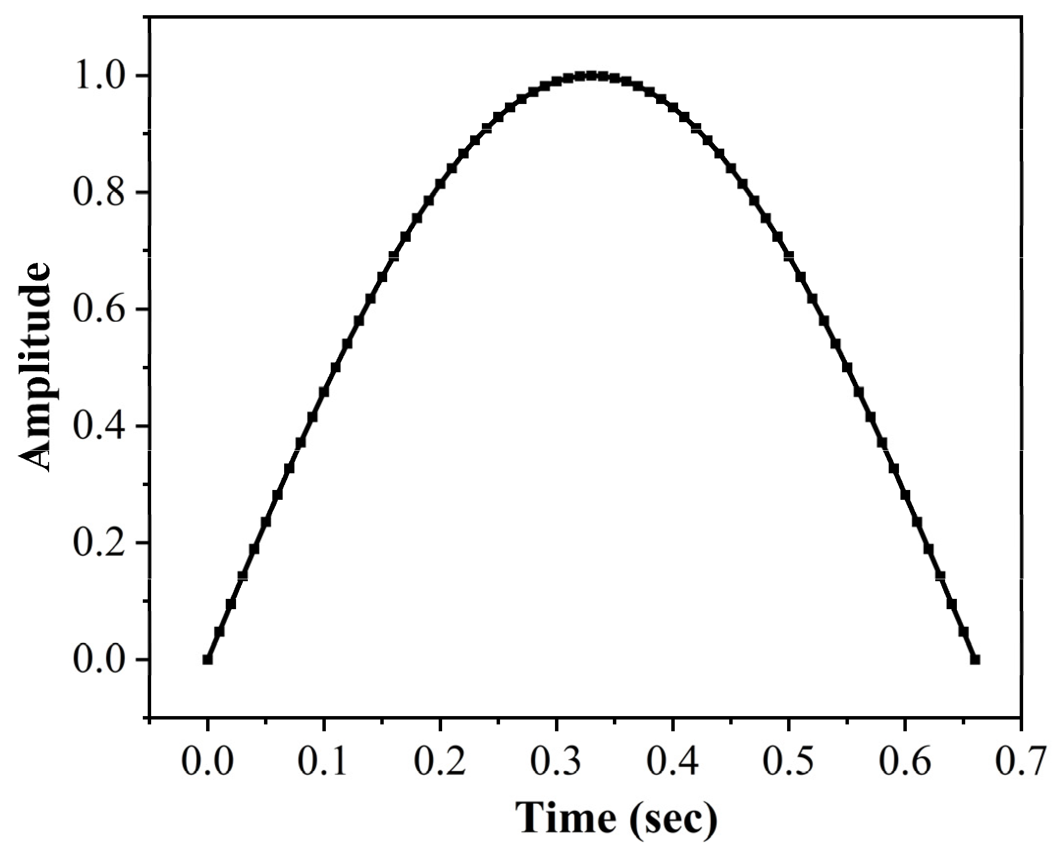
The static analysis ODB files of the nominal blade and optimized blade from ABAQUS were imported to the FE-SAFE module.
Figure 14 shows the load cycle used to perform the fatigue analysis of the nominal and optimal blade geometries. One blade hook was used for the fatigue analysis and the load cycle was approximated using a similar hook cutter to increase the computational efficiency [
58]. The load cycle was developed using the “signal generation” function in FE-SAFE. Considering the given speed of the shredding system as 30 rpm, one cycle of the blade is completed in 2 s. Multiplying the cycle time with the contact ratio (1:3) provides the cycle time of a single hook to be two-thirds of a second. Hence, the time-dependent load cycle with a unit amplitude was plotted in the “signal generation settings” of FE-SAFE and is shown in
Figure 14. The H-550 material database was created since no equivalent material database is available in the FE-SAFE default material database, and the Morrow stress-life algorithm was selected to predict the fatigue life. The models were then analyzed for fatigue life; however, no damage was observed in both models. This indicated that due to the high FOS and low F
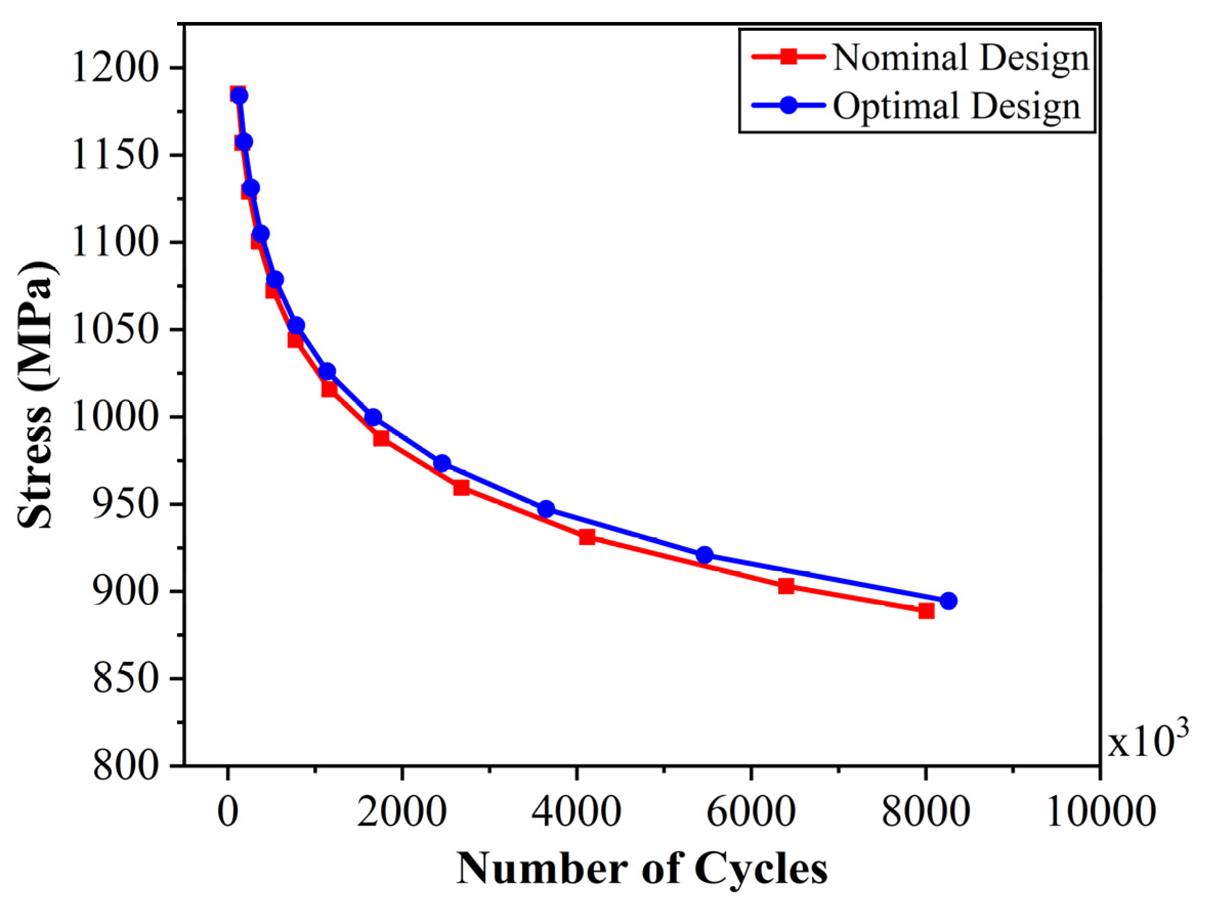
c, the blade model is safe; however, it is important to develop an SN-curve and address the uncertainties due to various material types present in medical waste. Therefore, the stresses were scaled using the “scale” function in FE-SAFE, and various points were obtained for the number of cycles against the stresses. To examine the effect of topology optimization on fatigue life, these points were fitted to the curves shown in
Figure 15. Although a similar curve is obtained for both the geometries, the optimal blade has a 14.5% increased fatigue life than the nominal blade when comparing the number of cycles at identical stresses. This indicates the relaxation of the stress concentration points during the optimization process and is advantageous in increasing the fatigue life of the shredding system.
3.6. Weight Saving
Table 4 shows the weight saving achieved by the optimization process. The weight of a nominal shredder blade used in the current system is 10.76 kg. However, it has been estimated that the blade weight was reduced by 24.7% to 8.26 kg after topology optimization. There are 22 blades in the system, hence the net weight reduction is estimated to be 55 kg which is substantial for the system. Such weight saving increases the material efficiency and can significantly affect the operational cost and power consumption, resulting in a sustainable design that reduces the environmental impact throughout the blade life. The material removal during the topology optimization process is observed in the outer surface causing a reduction in blade diameter, which is also beneficial during the flow of the waste because it reduces the bottleneck and provides a larger flow volume for shredded waste to bypass the blades. Therefore, for future work, it is recommended to apply a similar optimization strategy to the other structural and non-structural components of the shredding system. In addition, the adopted topology optimization methodology can be applied for the sustainable design of components in other mechanical engineering sectors such as the automotive and aerospace industries. The current studies also contribute to improving the understanding of how reverse engineering can be successfully applied for structural topology optimization to solve complicated design problems without compromising performance and integrity while generating a lightweight material-efficient structure.
3.7. Blade Fabrication and Future Work
The actual prototype of the nominal design shown in
Figure 16 has been manufactured with the assistance of Samyoung Plant Co., Ltd., South Korea. The fabrication of the prototype has been completed using the subtractive manufacturing processes. The inner hexagon has been formed using the machining center, with round edges to eliminate the stress concentrations and ease the blade fit on the shaft. The outer boundary and the cutting tip have been manufactured using the water jet cutting, while the surface finishing has been achieved through milling. The manufactured blades have been installed in a 100 kg/hour sterilization-based shredding system which is currently in operation. For the optimal design, since the current research is the first attempt at the optimization of a shredding system, hence it is focused on developing a material optimization framework, and the physical realization is beyond the scope of the current work. However, this can be adopted in future work by validating the current results of optimal design through an experimental setup.
4. Conclusions
This paper presents a design optimization process, which includes mathematical and numerical methods to optimize a shredding system modeled through reverse engineering. The blade model is optimized using topology optimization, and a comparison of stress characteristics and fatigue life was performed for the nominal and optimized blade design. The present shredder blade problem has the simplest problem formulation in terms of objective function and constraints, i.e., designing for minimum compliance under simple boundary conditions and volume constraints. To ensure that the optimum shape is compatible with other design characteristics such as the strain energy, blade weight, von Mises stress, and maximum displacement, multiple numerical cases were simulated for various volume constraints. All design parameters were observed to optimize at 80% volume constraint, therefore inducing a maximum overall weight reduction of 24.7% while fulfilling the strength and stiffness objectives. Material removal was mostly observed at the blade boundary, thereby speeding up the optimization process. However, holes were formed within the design domain when volume constraint was reduced below VC80, generating infeasible geometries. To ensure manufacturing compatibility, the design directions established during optimization were utilized to enhance the design with minor geometric changes. The same VC80 model also demonstrated promising results by reducing the von Mises stress by 6 MPa. The estimated fatigue life of the optimal design at VC80 was also observed to increase by 14.5% as compared to the nominal design. Therefore, the best structural layout inside the design domain with a given set of objective functions and constraints was obtained at VC80 while optimizing all design parameters such as strain energy, mass, von Mises stress, and displacement. In addition, the developed methodology is easy to implement and has proven to significantly reduce the weight of the blade and increase the fatigue life without compensating for the integrity of the system. Thus, improving the material efficiency and consequently reducing the environmental impact of the traditionally overdesigned shredding systems. Therefore, it is expected that these promising results will encourage the shredder manufacturing industry to implement such a strategy to reduce the material cost and operational cost throughout the life cycle of the shredder system. The proposed methodology can also be extended and implemented in the automobile and aerospace industry to obtain lightweight, sustainable components without compromising structural integrity and performance.


