Article

Coupling Effect Suppressed Compact Surgical Robot with 7-Axis Multi-Joint Using Wire-Driven Method

1
Department of Biomedical Engineering, College of Medicine, Gachon University, 38-13, Dokjom-ro 3, Namdong-gu, Incheon 21565, Korea
2
Medical Devices R&D Center, Gachon University Gil Medical Center, 21, 774 Beon-gil, Namdong-daero, Namdong-gu, Incheon 21565, Korea
3
Department of Biomedical Engineering, College of Health Science, Gachon University, 191 Hambakmoero, Yeonsu-gu, Incheon 21936, Korea
4
Department of Health Sciences and Technology, Gachon Advanced Institute for Health Sciences and Technology (GAIHST), Gachon University, 38-13, 3 Dokjom-ro, Namdong-gu, Incheon 21565, Korea
*
Author to whom correspondence should be addressed.
Kicheol Yoon and Sung-Min Cho contributed equally to this study and are considered lead (first) co-authors.
Mathematics 2022, 10(10), 1698; https://doi.org/10.3390/math10101698
Submission received: 21 April 2022 / Revised: 11 May 2022 / Accepted: 14 May 2022 / Published: 16 May 2022
(This article belongs to the Topic Dynamical Systems: Theory and Applications)

Abstract

:
Currently, the most prevalent surgical treatment method is laparoscopic surgery. Robotic surgery has many advantages over laparoscopic surgery. Therefore, robotic surgery technology is currently constantly evolving. The advantages of robotic surgery are that it can minimize incision, bleeding, and sequelae. Other advantages of robotic surgery are that it can reduce hospitalization, recovery period, and side effects. The appeal of robotic surgery is that it requires fewer surgical personnel compared to laparoscopic surgery. This paper proposes an ultra-compact 7-axis vertical multi-joint robot that employs the wire-driven method for minimally invasive surgery. The proposed robot analyzes the degree of freedom and motion coupling for control. The robot joint is composed of a total of seven joints, and among them, the 7-axis joint operates the forceps. At this time, the forceps joint (#7 axis) can only operate open and close functions, while the link is bent and rotatable, regardless of position change. This phenomenon can be analyzed by Forward Kinematics. Also, when the DOF rotates, the passing wires become twisted, and the wire is generated through length change and coupling phenomenon. The maximum rotation angle of DOF is 90° and the rotating passing wire is wound by the rotation of the wire pulley. If the DOF is rotated to the full range of 120°, the second DOF will be rotated to 90°, and at this time, the coupling phenomenon caused by the first DOF rotation can be eliminated. The length change and the robot joint angle change related to the motor drive, based on the surgical robot control using the wire-driven method, are correlated, and the values for the position and direction of the end effector of the robot can be obtained through a forward kinematic analysis. The coupling problem occurring in the wire connecting the robot driving part can be solved through a kinematic analysis. Therefore, it was possible to test the position of the slave robot and the performance of the surgical forceps movement using the master system.

1. Introduction

For advanced surgery, surgical robots are being heavily invested in in hospitals and medical institution development centers [1]. The advantages of robotic surgery are that the incision, bleeding, sequelae, hospitalization period, recovery period, and side effects are reduced, the accuracy of surgery is enhanced and handling of the surgeon reduced [2,3].
In existing laparoscopic surgery, the manipulated radius is limited, because the manipulate is linear and the manipulated end-effector is always fixed. Therefore, due to the limited radius of the manipulate, the viewing angle is very limited and there are many difficulties in the surgical procedure. To overcome this limitation, a robot with a high degree of freedom was developed, and this robot was designed to move freely like a human hand and arm through ergonomic analysis. Therefore, the robot has eliminated the hand-shake phenomenon, and this function can move freely like a human hand. The surgical robot was designed to allow surgery to the deepest parts of the body because both hands can be freely used [4].
Robots used in hospitals are classified for biopsy and surgery [3,5,6,7,8,9,10,11,12,13,14,15]. Robot manipulate application cases include MRI brain tumor examination (Calgary University), ultrasound breast cancer examination (Virginia University), three-dimensional (3D) fluorescence image breast cancer examination (Duke University), ultrasound bladder disease examination (Tokyo University), and CT images. Lung examination (MIT) is discussed in [5,6,7,8,9,10,11]. In surgery robots, the AESOP, ZEUS, and Da Vinci (Intuitive Surgical Inc., Da Vinci, CA, USA) are representative surgical robots, having technical performance that is recognized [3,4,5,6,7,8,9,10,11,12,13,14,15]. However, the disadvantage of the robots is the low degree of freedom (DOF) of the end effector, which limits the joint angle, resulting in a narrow field of view radius of surgery [16,17,18]. Additionally, the low DOF of the end effector makes important triangulation impossible during surgery [19]. To solve this problem, end effectors with multiple DOFs are being actively developed [20,21,22].
The method of operating the joint of the surgical robot includes a direct motor connection method for the joint and a wire-driven method for transmitting wire power outside the motor. The wire-driven method is mainly divided into full-body wearable robots and partial wearable robots in the field of rehabilitation treatment [23,24]. This is because the angle of the robot joint is free to change. Therefore, it is possible to transmit power through the wire in the linear motion using the length (L) change of the rotational motion. This method can reduce the size and weight of the robot [25]. Thus, it can be applied to surgical robots. However, the wire-driven application method has a limitation in surgical procedure that requires various postures. It is very sensitive to changes in the length of the wire in the pulling and pushing of the wire connected to the joint. Therefore, it is concluded that if the joint connection is increased, the error, due to the change in the length of the wire, will increase [26]. For solving these problems, this paper proposes a small surgical robot based on a wire-driven method using kinematics and analysis of coupling phenomena [27]. The proposed robot is small and light and operates stably. It has a 7-axis joint end effector and a wide surgical radius. To evaluate the performance of the designed robot, the triangulation operation, and the position-tracking function of the master–slave system was tested [28,29].
In this work, Section 1 introduces the motivation for this research, and Section 2 and Section 3 refer to mechanism design and analysis. Section 4 is a discussion and Section 5 concludes the article.

2. Mechanical Design

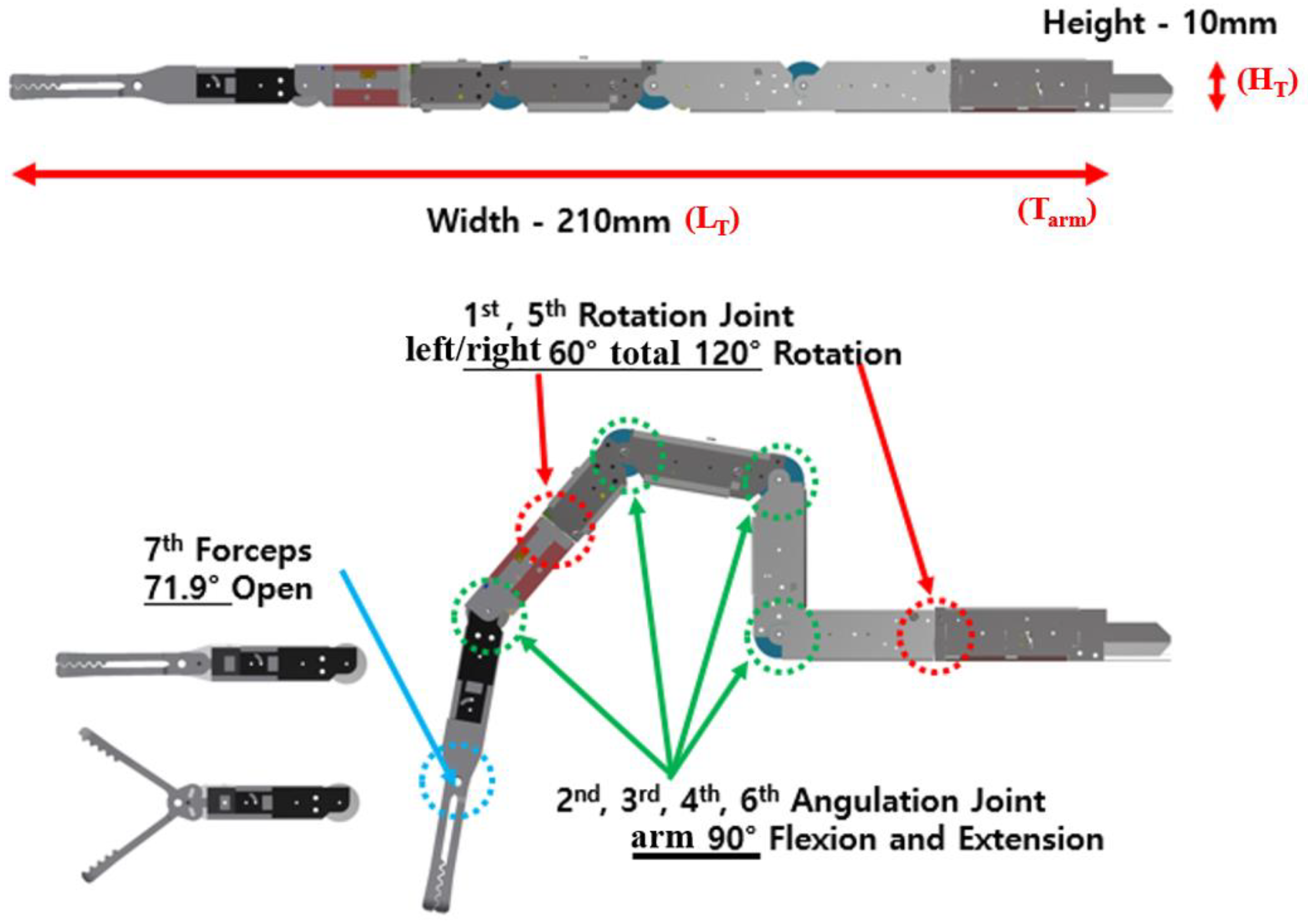
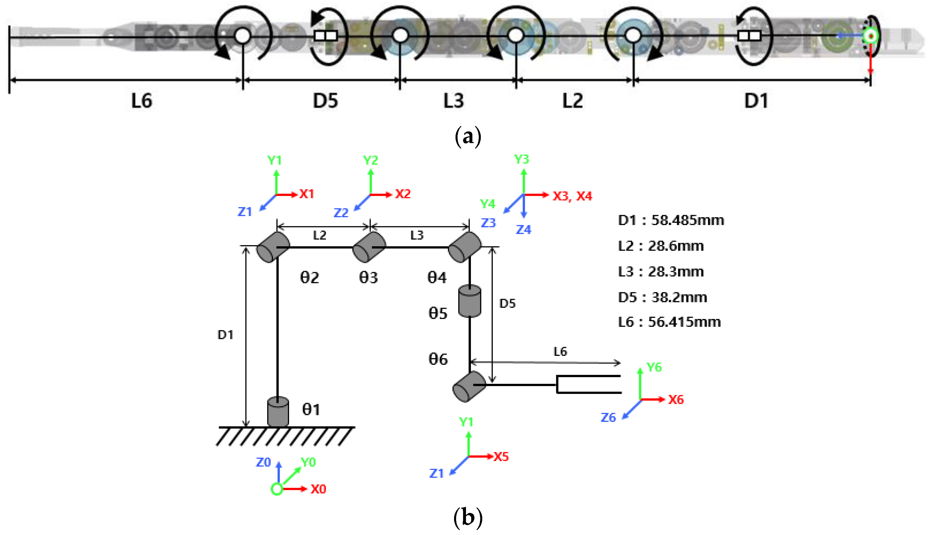
2.1. 7-Axis Vertical Multi-Joint Robot

The end effector of the proposed small vertical multi-joint surgical robot is shown in Figure 1. The total length (LT) and height (HT) are 210 and 10 mm, respectively. The inner and outer diameters of the ports are 14 and 16 mm, respectively. For the 7-axis joint (Di @ i = 1 to n) of the robot, the 1st and 5th axes are for rotation (left, right 60°; total 120° rotation), and the 2nd-4th and 6th axes are the angulation axes, θi (90°); θi is 1 to n (i = 1 to n).
Axis 7 moves the forceps and can be opened at an angle (θ = 1 to 7) of up to 71.9° from the axis. The wire for driving the shaft is connected to two wires (Li @ i = 1 to 7). The first wire drives the extension (right), and the second wire (Li) drives the flexion left). At this time, the extension and flexion wires play the roles of pulling and pushing, respectively, and in some cases operate in opposite directions. The problem to be solved here is that, owing to the coupling phenomenon, malfunction of extension and flexion due to the wire occurs. If the wire (Li) is pushed and pulled through the joint (D), the rotation angle (θ) for the rotation (R) causes a coupling phenomenon. Therefore, in the process of moving the manipulator (Tarm), the rotation angle (θ1) of the 1-axis joint (D) to the rotation angle (θ6) of the 6-axis joint (D) do not match, resulting in malfunction. Also, since the movement of the manipulator (Tarm) is not accurate, it leads to incorrect operation during the operation [30,31]. A method to reduce the coupling phenomenon is very important in the development of surgical robots.
The radius of rotation (R:Rinside and Routside) of the manipulator (Tarm) has a rotation angle (θ) between 0° and 90°. At this time, if an error occurs in the rotation angle (θ) in the movement phenomenon of the 1-axis joint (D) to the 6-axis joint (D), the manipulator generates a malfunction within the error range. Therefore, in order to move the manipulator (Tarm) accurately, the error range of the rotation angle (θ) should be close to 0°, which will produce excellent operating characteristics for the manipulator [31].
For this reason, the radius of rotation (R) for each joint (D) of the real manipulator (Tarm) should be linear in the range of rotation angle (θ) from 0° to 90°, as shown in Figure 2 (matlab 2021 and origin pro 9.0). Therefore, within the linear range, the wire (LT) length should be within 150 mm, because the error range of the rotation angle (θ) is within 20°, and elasticity, rigidity, and elongation will be minimized.
If the length (LT) of the wire exceeds 150 mm, the wire will not be able to withstand the weight and will lose tension. So, the wire will stretch as length increases. For this reason, the manipulator will malfunction due to over coupling [31]. Therefore, it is necessary to increase the accuracy of the operation through an analysis of the coupling.

2.2. Relationship between Motor Length Change and Surgical Robot Joint Angle

In the surgical robot, the forward and inverse kinematics for the position movement, and the direction of the end effector and the length change of the motor, are divided into two parts, as shown in Figure 3 [27,32,33,34]. The first part is related to the motor length (LT) and the robot joint angle (θi), and the second part is related to the robot joint angle (θi) and the position/direction (x, y, z) of the end effector.
Table 1 presents the motor length and angle of each axis of the robot. The drive motor connecting the wires of each axis of the robot uses a reduction gear (Maxon), and the motor and encoder are 4096 pulse/1 rotation in an integrated resolution. For increasing the magnitude of the torque, the front part of the motor has a ratio of 150:1 and is equipped with a precision reduction gear. A pulley (diameter of 15 mm) is attached to the motor shaft, and the wire (Li and LT) is designed to withstand up to three turns, R (141.37 mm). Therefore, the wire (Li) is strong and does not stretch. Since the wire has a certain level of tension, the length of extension and flexion does not change, and the operation is smooth. As shown in Figure 4, if the wire length (LT) has a linear response characteristic between 0 mm and 141.37 mm (within 0–90°/rotation angle error range: within ±15°), the wire maintains tension. However, if the length of the wire exceeds 141.37 mm, over coupling occurs and the range of the coupling phenomenon has non-linear response characteristics [30,31]. Eventually, the wire (LT) loses tension and causes malfunction (incorrect rotation radius (R)) [30,31].

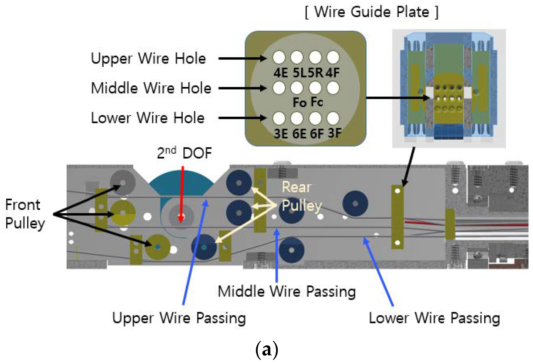
3. Analysis of Wire-Driven Robot Arm

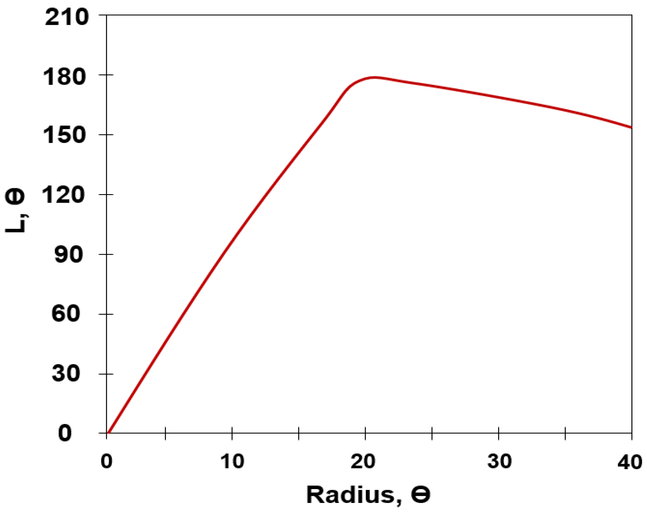
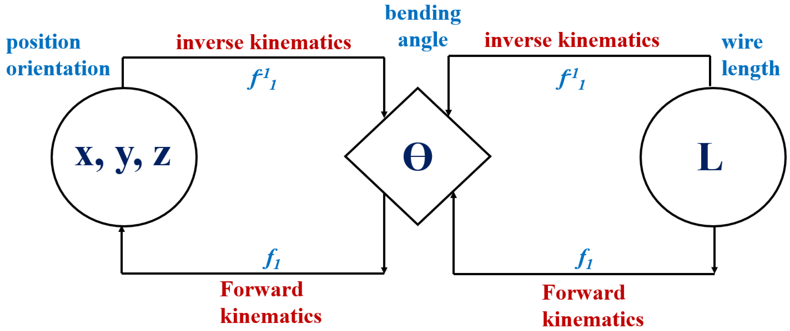
3.1. Forward Kinematics

The manipulator (Tarm) is composed of 7-axis joints (Di @ i = 1 to 7), and the end-effect part is connected by forceps. The robot has a rotation function opposite to rotation (R) for each joint (D). This manipulator is docked into the abdominal cavity through a trocar (Holl instrument for inserting the manipulator into the abdominal cavity) during laparoscopic surgery (the procedure for inserting a surgical tool into the abdominal cavity). The wire (Li) uses polyethylene. The reason is that it is strong and does not stretch. Therefore, the thickness of the wire is 0.165 mm and the tensile strength is 1.68 kg. Since the robot joint consists of a total of seven axes, the 7-axis (θ) joint (D) moves the focus. At this time, only the open/close operation is performed through the breakage and rotation (R) of the link, regardless of the position change of the forceps. Therefore, forward kinematics are analyzed for the six axes (D), as shown in Figure 5a.
The Denavit–Hartenberg method is used in conjunction with the manipulator’s forward kinematics equation. The multi-DOF robot sets the Denavit–Hartenberg method and the coordinates of each axis of the surgical robot to analyze the complex transformation relationship between the fixed base frame and the end-effector frame, as shown in Figure 5b. Thus, a DH parameter table is created [35].
Table 2 presents (visual studio 2017) the parameters related to each link and joint in the Denavit–Hartenberg method. θ1 has the origin of the base coordinate system, as shown in Figure 5b, which becomes the reference position of all the axes. θ2, θ3, and θ4 are located at the joint center, and θ5 is located at θ4.
θ6 is located at the joint center. Therefore, the transformation determinant (i + 1iT) and the total transformation determinant ( T 6 0 ) from the base axis coordinate system, based on the forward kinematic analysis to the axis of the last term, are given by Equation (1). Here, cos(θi) and sin(θi) are denoted as Ci and Si, respectively.
T 1 0 = [ C 1 0   S 1 0 S 1 0 C 1 0 0 1 0 D 1 0 0 0 1 ] T 2 1 = [ C 2 S 2 0 L 2 × C 2 S 2   C 2 0 L 2 × S 2 0 0 1 0 0 0 0 1 ] T 3 2 = [ C 3 S 3 0 L 3 × C 3 S 3   C 3 0 L 3 × S 3 0 0 1 0 0 0 0 1 ] [ C 4 0   S 4 0 S 4 0 C 4 0 0 1 0 0 0 0 0 1 ] T 5 4 = [ C 5 0 S 5 0 S 5 0   C 5 0 0 1 0 D 5 0 0 0 1 ] T 6 5 = [ C 6 S 6 0 L 6 × C 6 S 6   C 6 0 L 6 × S 6 0 0 1 0 0 0 0 1 ]
The end-position coordinates P (x, y, z) of the robot in the reference coordinate system are calculated using Equation (2).
T 6 0 = T 1 0 T 2 1 T 3 2 T 4 3 T 5 4 T 6 5 = [ R ( r n m , r n m , r n m ) P ( x ,   y ,   z ) 0 0 0 1 ]
From the results in Table 2, the result of the manipulator for the operation of the entire 7-axis joint is that the length of the wire (Li) at the 1st-axis joint (D) is changed to 58. 485 mm. At this time, the rotation angle (θ1) for D1 is changed from −60° to +60°. At the 2nd axis joint (D), the wire length (L2) changes up to 28.6 mm, and at this time, θ2 rotates from +90° to +180°. At joint (D) about the 3rd axis, the length of the wire (L3) has a change of 28.3 mm, and θ3 by L3 rotates from −90° to 0°. D2 and D3 have a value of 0 mm. The 4th axis joint (D) is the reverse motion to the 3rd axis joint, and θ4 rotates in the reverse direction from 0° to +90°. The joint (D) of the fifth axis has an inverse motion relation with the joint of the first axis. At this time, the rotation radius of θ5 is −60° to +60°. The joint D6 by the 6th axis has an inverse motion relation with the 2nd axis joint, and the rotation angle of θ6 is broken from −180° to −90°. The seventh axis joint (D) has rotation angles of 60° and 90°, respectively.
For the ideal operation of the manipulator, the error for the rotation angle (θ) of the N-axis joint is 0°. However, in the actual operation process, the error range for the rotation angle (θ) of the N-axis joint should be within 10°. However, in the actual field, the error for the rotation angle (θ) of the N-axis joint is within the range of 0° to 90°, and the error is within the range of ±15° [30]. This error range is recognized as the point where the coupling occurs, and the wire length (L1) changes due to the rotation angle error for the joint, which eventually causes the manipulator to malfunction.

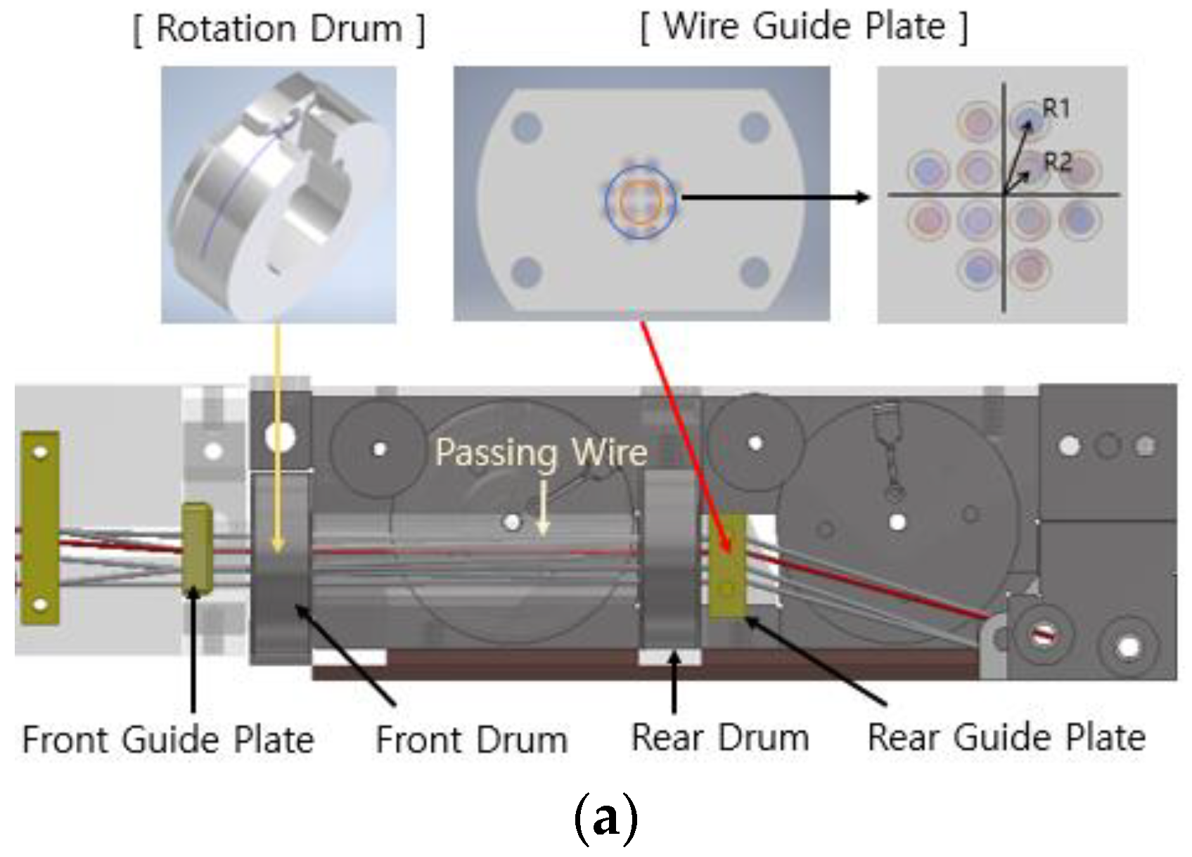
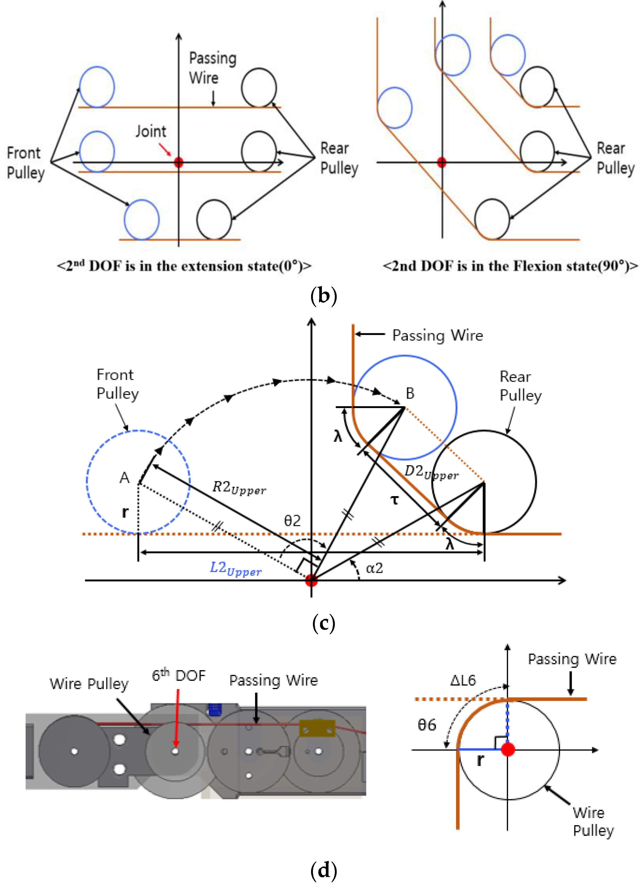
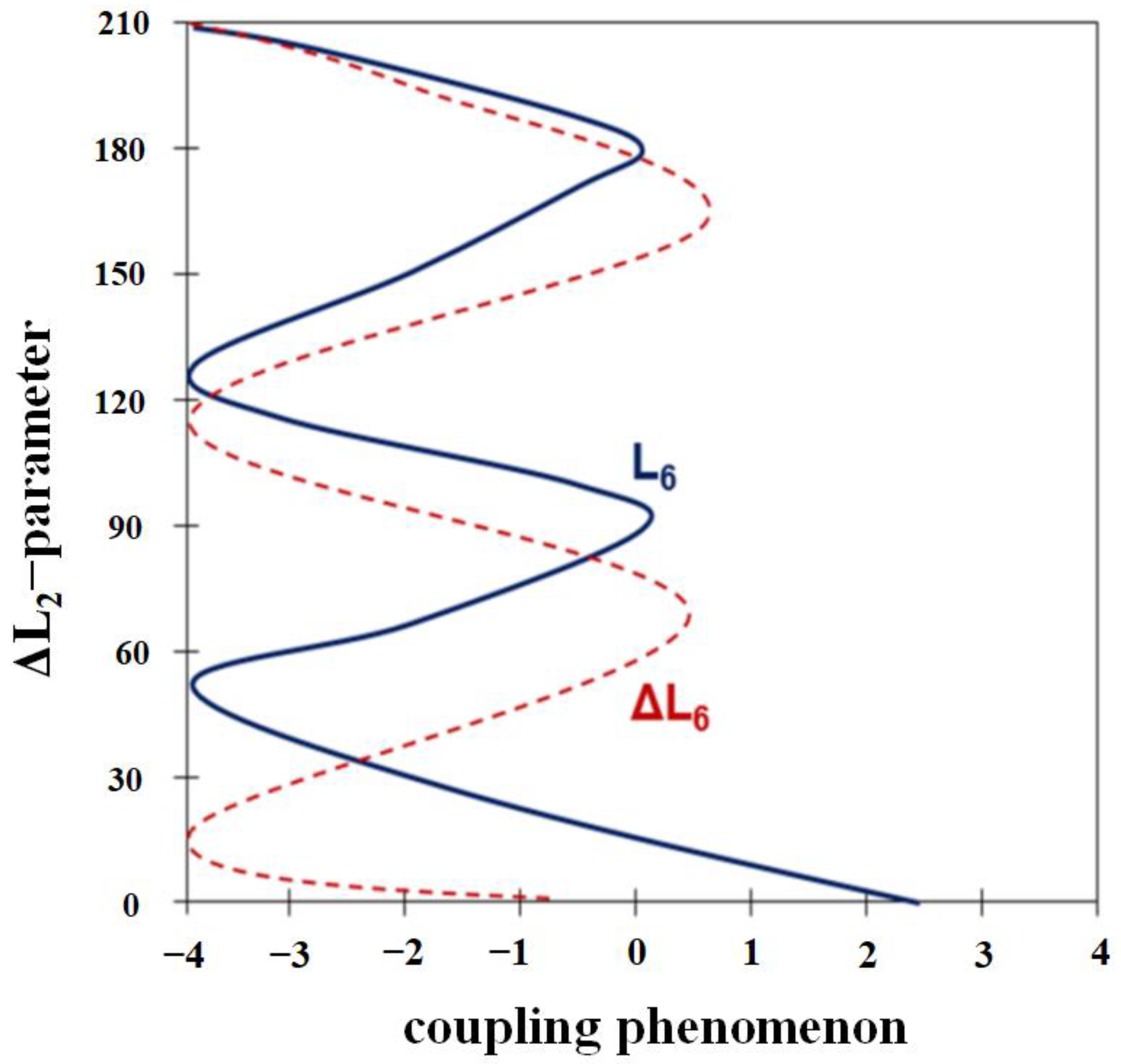
3.2. Coupling Analysis of Rotation Joint

The 1st and 5th DOFs in the joint of the surgical robot and the 2nd, 3rd, 4th, 6th, and 7th DOFs of the angulation joint are composed of rotation joints, as shown in Figure 6a. The wire (total 12 ea) for driving the 2nd–7th DOFs passes through the guide plate to the rotation drum. When the 1st DOF rotates, the passing wires (L1) are twisted, the length of the wire changes, and coupling occurs.
To solve this problem, it is necessary to analyze the rotational motion characteristics and arrangement structure of the wire guide plate. The inside and outside have four and eight holes, respectively, and the inside circle has a wire guide plate. When the motor rotates, a double method is designed to block interference between the wires. For a circle, the inner and outer radii are denoted as Rinside and Routside, respectively.
Figure 6b shows an example of the coupling phenomenon for the 1st DOF assuming a 90° rotation (R) in the left direction. At 0°, it is assumed that the length of the passing wire passes through the front and rear guide plates (L1) and the wire hole point (A) of the front guide plate. If the 1st DOF rotates 90° to the left, the length of the passing wire changes to D outside. Additionally, the wire hole moves to point (B). The length of change (L1 → ΔL1) for the rotation angle (θ1) of the wires passing through the guide plate is analyzed using Equation (3), because a coupling phenomenon occurs.
D Outside = ( L 1 2 + 2     R Outside 2 ( 1 cos ( θ 1 ) ) ) ,       Δ L 1 Outside = L 1   D outside D Inside = ( L 1 2 + 2     R Inside 2   ( 1 cos ( θ 1 ) ) ) ,       Δ L 1 Inside = L 1   D Inside
The 5th DOF is interpreted as the 1st DOF, as shown in Figure 6c, which is composed of a rotation joint structure. Four wires for driving the 6th and 7th DOFs are passed. The changes in the length (L5) of the four passing wires with respect to the rotation angle (θ5) were analyzed as a coupling phenomenon, as indicated by Equation (4).
D 5 = L 1 2 + 2 R 5 2 ( 1 cos ( θ 5 ) ) ,   Δ L 5 = L 5 D 5
Through the analysis of Figure 6 and Equation (3), as shown in Equation (4), the coupling occurs at the rotation angle (θ) of D5, and the result of operation with high accuracy will be shown by suppressing the coupling phenomenon. If the coupling is suppressed at the rotation angle (θ), the gap between Dinside and Doutside will be reduced. So, D5 should be 0 (D5 = 0, uncoupling).
Figure 7 shows the response characteristics to the coupling phenomenon of Dinside, Doutside, and D5. If the gap between Dinside and Douside is eliminated, the rotation angle (θ) of D5 will have a value of 0.

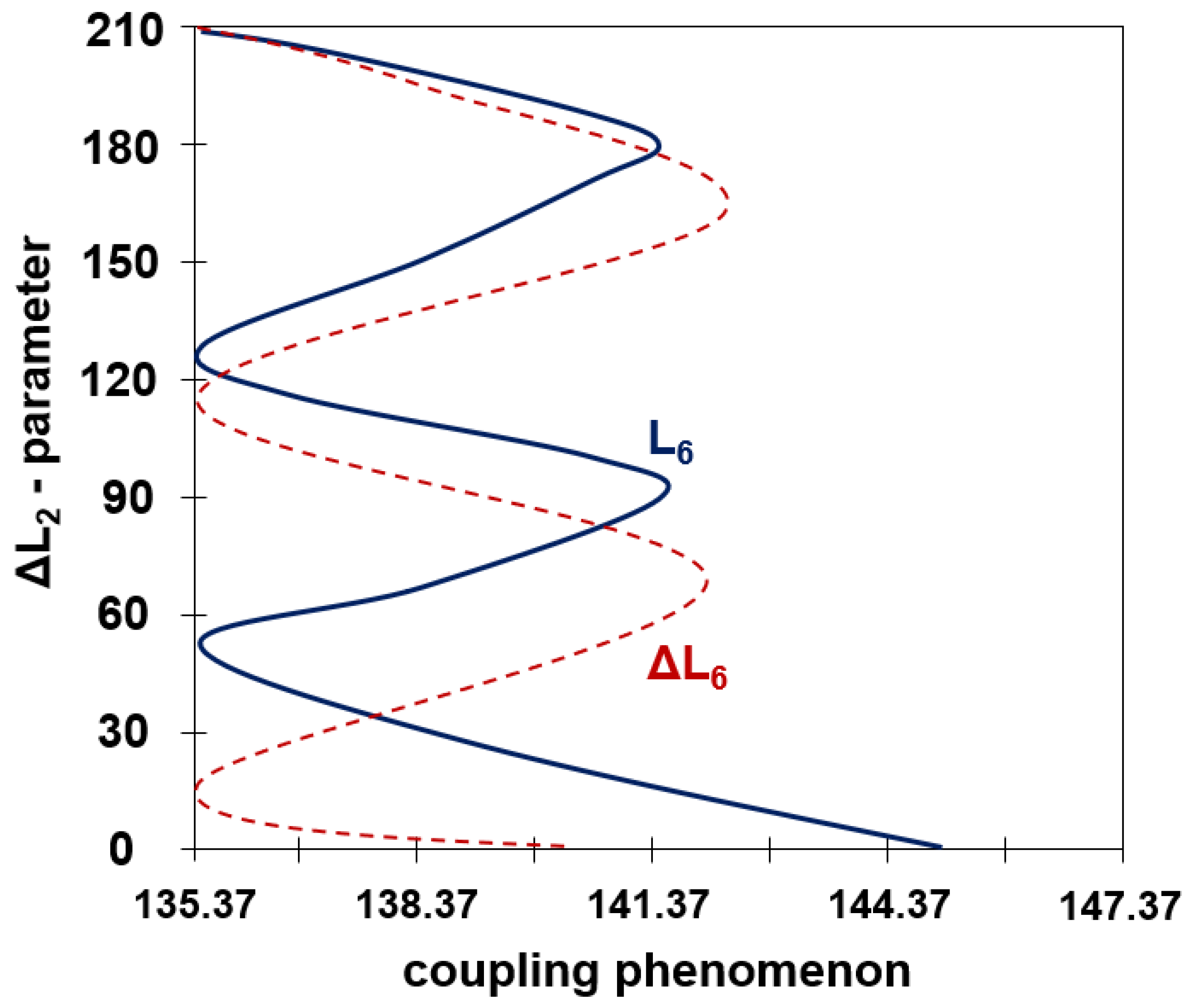
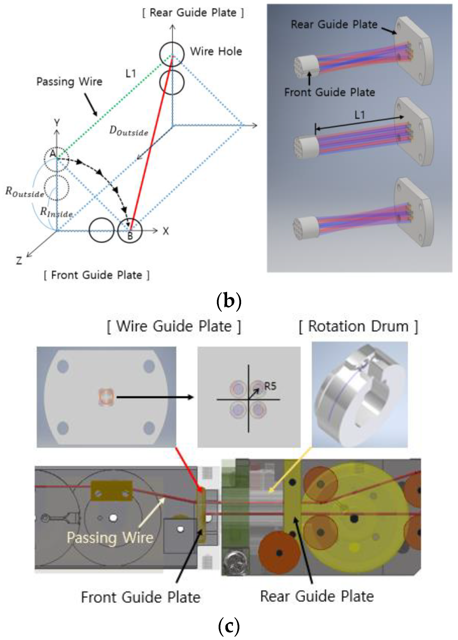
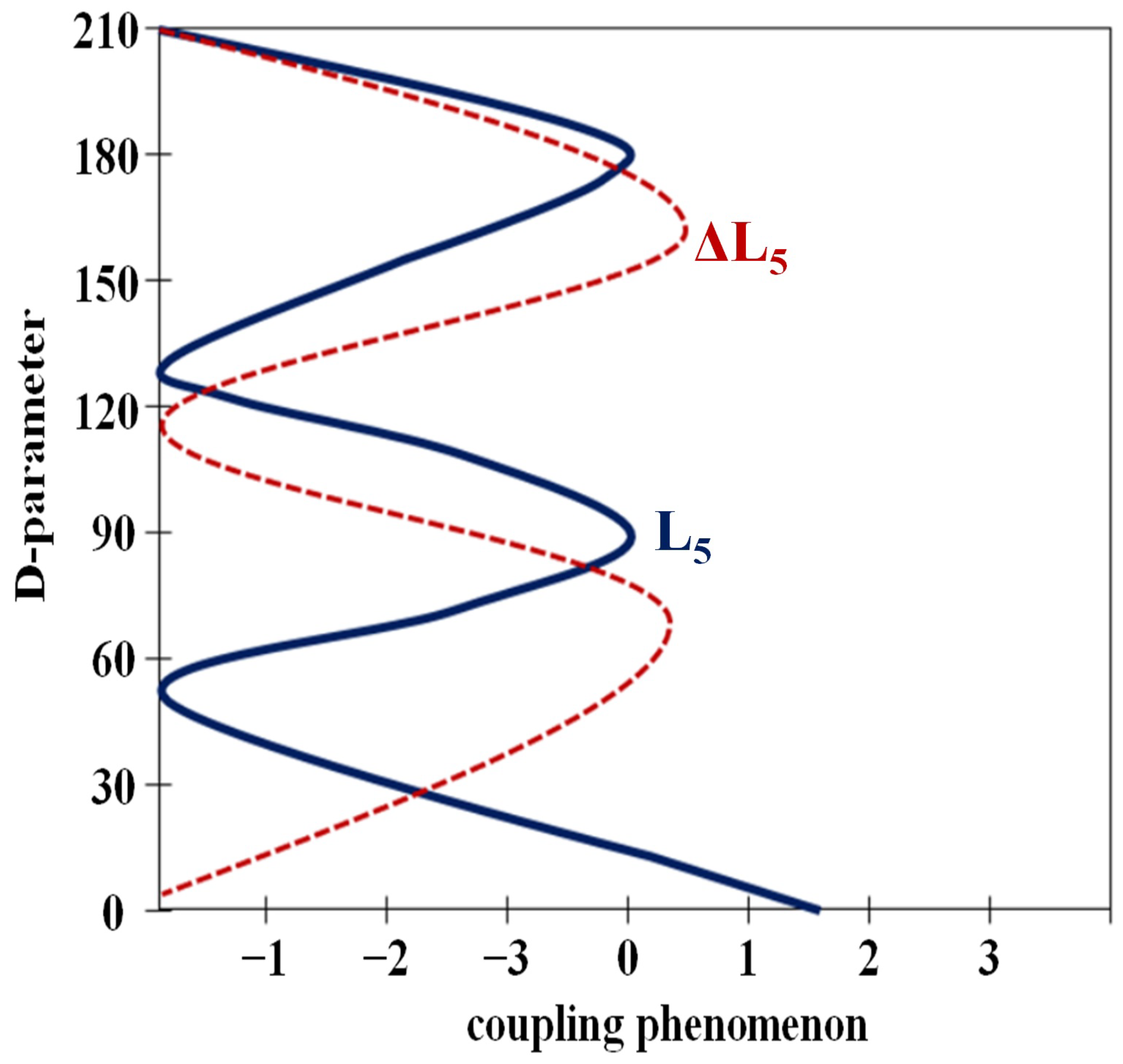
3.3. Coupling Analysis of Angulation Joint

To analyze the coupling of a joint with an angulation joint structure, the first and second DOF configuration diagrams should be analyzed, as shown in Figure 8a. Then, the coupling of the 3rd, 4th, and 6th DOFs is analyzed using the same method.
The passing wires of the 1st DOF are designed with three-stage wire holes related to the upper, middle, and lower, and the designed structure passes through the guide plate. Therefore, the guide plate notifies the 2nd DOF. Each angulation joint operates wires responsible for extension and flexion. The rotation joint is denoted as E and F, and the wires for left and right motion are denoted as L and R, respectively. The wires for the forceps’ open and close operations are denoted as O and C, respectively. The upper end of the guide plate passes the 4E, 4F, 5L, and 5R wires for the 4th and 5th DOF drives. The Fo and Fc wires for the forceps drive pass through the middle end, and the 3E, 3F, 6E, and 6F wires pass through the lower end for the 3rd and 6th DOF operations.
In the 2nd DOF, a total of 10 passing wires for the 3rd–7th DOF operation pass through the pulley. The wire pulley is fixed in three stages at the front and rear of the joint standard. The maximum rotation angle (θ) is 90°. When the 2nd DOF rotates, the passing wires maintain the wire pulley status, which reduces the gap between the front and rear pulleys. Therefore, length (LT) change and coupling occur, as shown in Figure 8b. When the length of the wire passing through the front pulley and rear pulley at 0° in the extended state is assumed to be L2upper and the center point of the front pulley is point A, the 2nd DOF rotates by 90°. The length of the through wire (LT) changes to D2upper. Therefore, as soon as the center point moves to point B, the length L2upper is given by Equation (5).
L 2 upper = 2 R 2 upper 2 ( 1 cos ( π 2 α 2 ) )
In the flexion operation of 90° (θ) rotation (R), the change length D2upper of the passing wire (LT) is the distance between the front (point B) pulley and the center point of the rear pulley, as shown in Equation (6), and this is the total length of λ corresponding to the pulley.
λ =   r ( θ 2 ) / 2 , τ = 2     R 2 Upper 2 ( 1 cos ( π 2 α 2 θ 2 ) ) , D 2 Upper =   τ   + 2 λ , Δ L 2 Upper =   Δ L 2 Upper Δ D 2 Upper
The length of the passing wire decreases with the change in ΔL2upper from L2upper to D2upper (within 5°). At this time, the wires passing through the upper end are wound by the motor according to the amount of change. When the extension state is rotated to the 0° position in the 90° flexion of the 2nd DOF, the distance between the center point of the front pulley and the rear pulley becomes large, as shown in Figure 8c. Therefore, the length of the wires passing through the upper end of the motor is loosened by the amount of change.
The change amounts at the middle and lower ends (ΔL2middle and ΔL2lower, respectively) can be determined in the same manner, as given in Equation (7).
Δ L 2 middle = 2 Δ R 2 middle 2 ( 1 cos ( π 2 β 2 ) ) 2 R 2 middle 2 ( 1 cos ( π 2 β 2 θ 2 ) ) r θ 2 Δ L 2 lower = 2 R 2 lower R 2 lower 2 ( 1 cos ( π 2 γ 2 ) ) 2 R 2 lower 2 ( 1 cos ( π 2 γ 2 θ 2 ) ) r 2 θ 2 .
The coupling analysis of the 3rd and 4th DOFs, with a structure similar to the 2nd DOF related to the angulation joint, is identical to the 2nd DOF analysis method.
The passing wire of the 6th DOF corresponds to the FO and FC wires related to the forceps driving through the pulley, as shown in Figure 8d. At this time, the maximum rotation angle (θ) is 90°, the rotating passing wires are wound around the wire pulley, and the wires rotate. The change in the length of the wire causes a coupling phenomenon.
In the 6th DOF extension state, the length of the passing wire of the 0° (θ6) flexion increases by ΔL6 of Equation (8) as follows:
Δ L 6 = r   ×   θ 6 .
Equation (8) through the analysis of Equation (7) causes the occurrence of coupling in L6. Therefore, the difference between the rotation angles θ between L2middle and L2Lower is minimized, and at this time, the rotation angle θ for L6 satisfies 0 (L6 = 0). For that reason, it is possible to suppress the coupling phenomenon to L6, and in this case, high accuracy can be expected for the manipulation of the joint rotation. So, if the coupling is suppressed, the difference in rotation angle (θ) between L2middle and L2Lower is reduced. In the end, L6 has no choice but to be a rotation angle (θ) of 0 as in Equation (9). Figure 9 shows the process of reducing (L6) the coupling phenomenon for Equation (9).
L 6 = L 2 lower + jL 2 middle tan β θ L 2 middle + jL 2 lower tan β θ = ( L 2 middle ) ( L 2 lower ) = ( L 2 middle L 2 lower ) 2   @   Δ L 6 = 0 ,   β θ = π / 2
From the figure, it can be confirmed that the coupling is reduced because L6 has a rotation angle of 0 (θ).

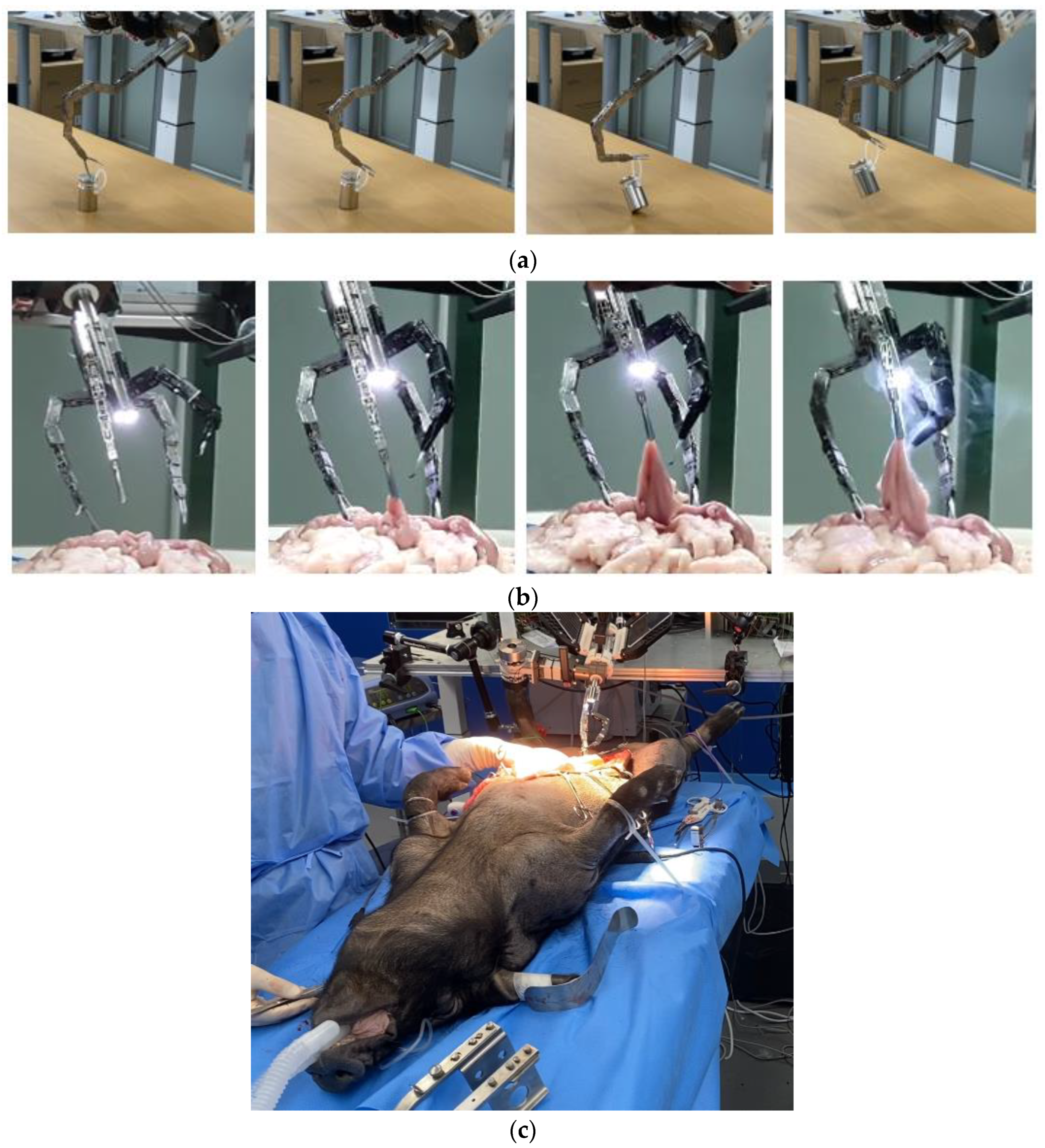
4. Experiment Validation

The values for Equation (9) were obtained using the triangulation method of Equations (7) and (8). Using Equation (9), a manipulator with coupling removed was manufactured using the design method as shown in Figure 8a. The manufactured manipulator was tested for reliability operation. When the plate is installed, as shown in Figure 8a, the difference in rotation angle (θ) is reduced to within 0° (within 5°), and high accuracy can be expected for the operation of the manipulator. The reason is that during the extension and flexion of the wire, it is very strong and has enough strength to pull the tissue when lifting, so reliability results were obtained through giblets and animal experiments. To check the overall motion and the performance of the forceps, a load test, involving holding and raising a “weight”, and a cooperative motion test, involving cutting the giblets, were tested, as shown in Figure 10a,b, respectively. Animal experiments were conducted in parallel, as shown in Figure 10c, to confirm whether actual operation is possible through the simultaneous operation and cooperation of four surgical robots. The animal was tested at the animal center of Osong Medical Innovation Foundation, KBIO (Osong Medical Innovation Foundation, KBIO). We obtained permission from the Animal Institutional Review Board (IRB) of the Animal Ethics Commission. The animal test involved a conventional-type pig (Farm/male (1 ea)/weight of 60 kg). It was confirmed that triangulation motion can be implemented with a 7-axis vertical multi-joint surgical robot through master system control. Thus, it was confirmed that the operating radius is wider, and the operating performance is excellent at all angles.
To evaluate the accuracy of the surgical robot, the 1st DOF was rotated over the full range (120°), and then the 2nd DOF was rotated by 90°. Coupling due to joint rotation is almost eliminated to 0°. Coupling measurement results were reached within 5°. This is an improvement of over 10° compared to [30]. We checked whether 90° rotation (R) of the 2nd DOF target was possible. To test the performance, the operation was repeated five times. After the 1st and 2nd DOFs were rotated in the full range, the 3rd DOF was rotated by 90°. To test the performance, measurements were performed five times, and the average value was calculated, as shown in Table 3. We tested the overlapping coupling phenomenon that occurs when the 1st and 2nd DOF rotations are removed, and whether the 3rd DOF targets 90° rotation is possible. To evaluate the performance, measurements were performed five times, and the average values are presented in Table 3. Thus, the 4th, 5th, 6th, and 7th DOFs were measured.
The rotational measurements and error values for the 1st–7th DOFs are presented in Table 3. The error overlapped as the number of consecutive DOFs increased from the 5th DOF. This means that the error value increased. Therefore, errors occurred in the mechanical backlash and tension of the wire.
The effect load of manipulator is 1.5 newton and 0.15 kg with down and uploaded which is used for force measurement system (imada) as shown in Figure 11.
In general, the surgical robot’s manipulator has six-axis joint freedom. Therefore, the radius is narrow for excising tissue during surgical procedure, and the operation becomes difficult. Also, due to over coupling of the manipulator, the rotation angle of the joint does not match, causing the wire to stretch or break, which may cause the manipulator to be damaged and make surgery impossible. In order to overcome this problem, it is important to design a robot with multi-degree freedom that reduces coupling and induces freedom of the 7-axis joint for convenient surgery and wide range of resection. Therefore, mechanism analysis is essential to solve these problems. In particular, the wire of the manipulator of the proposed robot uses a thin and strong polyethylene material so that it does not stretch or break. It will be applied to laparoscopic surgery area and endoscopy technique [36,37]. For example, surgery will be possible for rectal cancer, colorectal cancer, stomach cancer, and thyroid resection, and the urology department will be able to perform prostate cancer, bladder cancer, and kidney surgery. In addition, the obstetrics and gynecology department will be able to perform surgery for cervical cancer, endometrial cancer, ovarian cancer, benign tumors, myomectomy, salpingoplasty, reanaastomosis, and hysterectomy.
This study is a robot with 7-axis joint freedom, which is expected to be very useful for laparoscopic surgery in the future. We have a design plan.

5. Conclusions

We propose a miniature surgical robot design for minimizing incision size during laparoscopic surgery. A wire-driven method was adopted to implement a microrobot. The wire-driven method includes the motion-coupling problem, and a method to solve it is proposed. To solve the problem of the low DOF of the surgical robot, a design of a multi-DOF surgical robot composed of seven axes was proposed, and a prototype was manufactured. Experiments confirmed that the motion-coupling problem could be solved, and the operation performance of the surgical robot was evaluated.
The diameter (D) of the port of Da Vinci is 25 mm. The diameter of the port of the proposed surgical robot system is 16 mm, and the diameter of the surgical robot entering the port is approximately 14 mm. This maximizes the efficiency of minimally invasive surgery and reduces the patient’s recovery time by minimizing the incision area during surgery. However, for ensuring the precision of the microscopic motion of the surgical robot, it is necessary to minimize errors that occur in backlash and wire tension due to kinematic tolerances. To solve this problem, we plan to perform additional precise design and wire tension control device design in the future.

Author Contributions

Analysis and clinical study, K.Y. and Design and simulation, S.-M.C. Analysis and supervisor, K.G.K. All authors have read and agreed to the published version of the manuscript.

Funding

This research was supported by the MSIT (Ministry of Science and ICT), Korea, under the ITRC (Information Technology Research Center) support program (IITP-2021-2017-0-01630) supervised by the IITP (Institute for Information & Communications Technology Promotion), and by the GRRC program of the Gyeonggi province (No. GRRC-Gachon2020(B01)), respectively. In addition, the research was supported by the G-ABC FRD2019-11-02(3).

Institutional Review Board Statement

The experiment was animal test from the “experimental animal center of Osong Medical Innovation Foundation, KBIO ((KBIO-IACUC-2019-021) through the permission of animal institutional review board (IRB) at animal ethics commission.

Informed Consent Statement

Not applicable.

Data Availability Statement

The data presented in this study are available upon request from the permission corresponding author. The data are not publicly available because of privacy and ethical restrictions.

Conflicts of Interest

The authors declare no conflict of interest. The funders had no role in the design of the study; in the collection, analyses, or interpretation of data; in the writing of the manuscript, or in the decision to publish the results.

References

  1. Park, Y.-J.; Lee, E.-S.; Choi, S.-B. A Cylindrical Grip Type of Tactile Device Using Magneto-Responsive Materials Integrated with Surgical Robot Console: Design and Analysis. Sensors 2022, 22, 1085. [Google Scholar] [CrossRef] [PubMed]
  2. Zuo, S.; Chen, T.; Chen, X.; Chen, B. A Wearable Hands-Free Human-Robot Interface for Robotized Flexible Endoscope. IEEE Robot. Autom. Lett. 2022, 7, 3953–3960. [Google Scholar] [CrossRef]
  3. Lin, B.; Wang, J.; Song, S.; Li, B.; Meng, M.Q.-H. A Modular Lockable Mechanism for Tendon-Driven Robots: Design, Modeling and Characterization. IEEE Robot. Autom. Lett. 2022, 7, 2023–2030. [Google Scholar] [CrossRef]
  4. Prasad, S.M.; Ducko, C.T.; Stephenson, E.R.; Chambers, C.E.; Damiano, R.J. Prospective clinical trial of robotically assisted endoscopic coronary grafting with 1-year follow-up. Ann Surg. 2001, 233, 725–732. [Google Scholar] [CrossRef] [PubMed]
  5. Sutherland, G.R.; McBeth, P.B.; Louw, D.F. NeuroArm: An MR compatible robot for microsurgery. Int. Congr. Ser. 2003, 1256, 504–508. [Google Scholar] [CrossRef]
  6. Liang, K.; Rogers, A.J.; Light, E.D.; Allmen, D.; Smith, S.W. Three-dimentsional ultrasound guidance of autonomous robotic breast biopsy: Feasibility study. Ultrasound Med. Biol. 2010, 36, 173. [Google Scholar] [CrossRef] [Green Version]
  7. Shi, M.; Liu, H.; Tao, G. A stereo-fluoroscopic image-guided robotic biopsy scheme. IEEE Trans. Control Syst. Technol. 2002, 10, 309–317. [Google Scholar] [CrossRef]
  8. Hong, J.; Dohi, T.; Hashizume, M.; Konishi, K.; Hata, N. An ultrasound-driven needle-insertion robot for percutaneous cholecystostomy. Phys. Med. Biol. 2004, 49, 441–455. [Google Scholar] [CrossRef]
  9. Cleary, K.; Zigmund, B.; Banovac, F.; White, C.; Stoianovici, D. Robotically assisted lung biopsy under CT fluoroscopy: Lung cancer screening and phantom study. Int. Congr. Ser. 2005, 1281, 740–745. [Google Scholar] [CrossRef]
  10. Barrett, S.R.H.; Hanumara, N.C.; Walsh, C.J.; Slocum, A.H.; Gupta, R.; Shepard, J.O. A remote needle guidance system for percutaneous biopsies. In Proceedings of the ASME 2005 International Design Engineering Technical Conferences and Computers and Information in Engineering Conference, Long Beach, CA, USA, 24–28 September 2005. [Google Scholar]
  11. Walsh, C.J.; Hanumara, N.C.; Slocum, A.H.; Shepard, J.-A.; Gupta, R. A Patient-Mounted, Telerobotic Tool for CT-Guided Percutaneous Interventions. J. Med. Devices 2008, 2, 011007. [Google Scholar] [CrossRef] [Green Version]
  12. Da Col, T.; Caccianiga, G.; Catellani, M.; Mariani, A.; Ferro, M.; Cordima, G.; De Momi, E.; Ferrigno, G.; de Cobelli, O. Automating Endoscope Motion in Robotic Surgery: A Usability Study on da Vinci-Assisted Ex Vivo Neobladder Reconstruction. Front. Robot. AI 2021, 8. [Google Scholar] [CrossRef] [PubMed]
  13. Kapsalyamov, A.; Hussain, S.; Jamwal, P.K. A novel compliant surgical robot: Preliminary design analysis. Math. Biosci. Eng. 2020, 17, 1944–1958. [Google Scholar] [CrossRef] [PubMed]
  14. Du, C.; Wei, D.; Wang, H.; Wang, W.; Dong, J.; Huo, H.; Li, Y. Development of the X-Perce—A Universal FBG-Based Force Sensing Kit for Laparoscopic Surgical Robot. IEEE Trans. Med. Robot. Bionics 2022, 4, 183–193. [Google Scholar] [CrossRef]
  15. Cai, Y.; Choi, P.; Hui, C.-W.V.; Taylor, R.H.; Au, K.W.S. A Task Space Virtual Fixture Architecture for Teleoperated Surgical System with Slave Joint Limit Constraints. IEEE/ASME Trans. Mechatron. 2022, 27, 69–80. [Google Scholar] [CrossRef]
  16. Beard, R.E.; Khan, S.; Troisi, R.I.; Montalti, R.; Vanlander, A.; Fong, Y.; Kingham, T.P.; Boerner, T.; Berber, E.; Kahramangil, B.; et al. Long-Term and Oncologic Outcomes of Robotic Versus Laparoscopic Liver Resection for Metastatic Colorectal Cancer: A Multicenter, Propensity Score Matching Analysis. World J. Surg. 2020, 44, 887–895. [Google Scholar] [CrossRef]
  17. Black, D.G.; Hosseinabadi, A.H.H.; Salcudean, S.E. 6-DOF Force Sensing for the Master Tool Manipulator of the da Vinci Surgical System. IEEE Robot. Autom. Lett. 2020, 5, 2264–2271. [Google Scholar] [CrossRef]
  18. Ma, X.; Song, C.; Chiu, P.W.-Y.; Li, Z. Visual Servo of a 6-DOF Robotic Stereo Flexible Endoscope Based on da Vinci Research Kit (dVRK) System. IEEE Robot. Autom. Lett. 2020, 5, 820–827. [Google Scholar] [CrossRef]
  19. Wildan Gifari, M.; Naghibi, H.; Stramigioli, S.; Abayazid, M. A review on recent advances in soft surgical robots for endoscopic applications. Int. J. Med. Robotics Comput. Assist. Surg. 2019, 15, e2010. [Google Scholar]
  20. Berthet-Rayne, P.; Leibrandt, K.; Gras, G.; Fraisse, P.; Crosnier, A.; Yang, G.-Z. Inverse Kinematics Control Methods for Redundant Snakelike Robot Teleoperation during Minimally Invasive Surgery. IEEE Robot. Autom. Lett. 2018, 3, 2501–2508. [Google Scholar] [CrossRef]
  21. Ma, X.; Song, C.; Chiu, P.W.; Li, Z. Autonomous flexible endoscope for minimally invasive surgery with enhanced safety. IEEE Robot. Autom. Lett. 2019, 4, 2607–2613. [Google Scholar] [CrossRef]
  22. Jin, S.; Lee, S.K.; Lee, J.; Han, S. Kinematic model and real-time path generator for a wire-driven surgical robot arm with articulated joint structure. Appl. Sci. 2019, 9, 4114. [Google Scholar] [CrossRef] [Green Version]
  23. Wang, H.; Wang, S.; Zuo, S. Development of Visible Manipulator with Multi-Gear Array Mechanism for Laparoscopic Surgery. IEEE Robot. Autom. Lett. 2020, 5, 3090–3097. [Google Scholar] [CrossRef]
  24. Nisar, S.; Hameed, A.; Kamal, N.; Hasan, O.; Matsuno, F. Design and Realization of a Robotic Manipulator for Minimally Invasive Surgery with Replaceable Surgical Tools. IEEE/ASME Trans. Mechatron. 2020, 25, 2754–2764. [Google Scholar] [CrossRef]
  25. Rehan, M.; Saleem, M.M.; Tiwana, M.I.; Shakoor, R.I.; Cheung, R. A Soft Multi-Axis High Force Range Magnetic Tactile Sensor for Force Feedback in Robotic Surgical Systems. Sensors 2022, 22, 3500. [Google Scholar] [CrossRef]
  26. Hwang, M.; Kwon, D.S. K-FLEX: A flexible robotic platform for scar-free endoscopic surgery. Int. J. Med. Robot. Comput. Assist. Surg. 2020, 16, e2078. [Google Scholar] [CrossRef] [PubMed]
  27. Hwang, M.; Thananjeyan, B.; Paradis, S.; Seita, D.; Ichnowski, J.; Fer, D.; Low, T.; Goldberg, K. Efficiently Calibrating Cable-Driven Surgical Robots With RGBD Fiducial Sensing and Recurrent Neural Networks. IEEE Robot. Autom. Lett. 2020, 5, 5937–5944. [Google Scholar] [CrossRef]
  28. Yen, P.-L.; Chen, Y.-J. Contact Compliance Based Visual Feedback for Tool Alignment in Robot Assisted Bone Drilling. Sensors 2022, 22, 3205. [Google Scholar] [CrossRef]
  29. Wang, Z.; Zi, B.; Wang, D.; Qian, J.; You, W.; Yu, L. External Force Self-Sensing Based on Cable-Tension Disturbance Observer for Surgical Robot End-Effector. IEEE Sens. J. 2019, 19, 5274–5284. [Google Scholar] [CrossRef]
  30. Direkwatana, C.; Suthakorn, J.; Wilasrusmee, C. Development of wire-driven laparoscopic surgical robotic system, “MU-LapaRobot”. In Proceedings of the 2011 IEEE International Conference on Robotics and Biomimetics, Karon Beach, Thailand, 7–11 December 2011; pp. 485–490. [Google Scholar]
  31. Feng, M.; Fu, Y.; Pan, B.; Liu, C. A medical robot system for celiac minimally invasive surgery. In Proceedings of the 2011 IEEE International Conference on Information and Automation, Shenzhen, China, 6–8 June 2011; pp. 33–38. [Google Scholar] [CrossRef]
  32. Li, Z.; Du, R.; Lei, M.C.; Yuan, S.M. Design and analysis of a biomimetic wire-driven robot arm. In Proceedings of the ASME 2011 International Mechanical Engineering Congress & Exposition, Denver, CO, USA, 11–17 November 2011. [Google Scholar]
  33. Webster, R.J., III; Jones, B.A. Design and Kinematic Modeling of Constant Curvature Continuum Robots: A Review. Int. J. Robot. Res. 2010, 29, 1661–1683. [Google Scholar] [CrossRef]
  34. Trochimczuk, R.; Łukaszewicz, A.; Mikołajczyk, T.; Aggogeri, F.; Borboni, A. Finite element method stiffness analysis of a novel telemanipulator for minimally invasive surgery. Med. Simul. 2019, 95, 1015–1025. [Google Scholar] [CrossRef] [Green Version]
  35. Cho, S.M.; Chung, T.; Lee, J.S.; Yoon, K.C.; Kim, K.G. For end effector of surgical robot 5 axis master system development. In Proceedings of the 2019 International Conference on BioMedical Technology (ICBMT 2019), Da Nang, Vietnam, 20–23 February 2019. [Google Scholar]
  36. Nam, K.W.; Park, J.; Kim, I.Y.; Kim, K.G. Application of Stereo-Imaging Technology to Medical Field. Healthc. Inform. Res. 2012, 18, 158–163. [Google Scholar] [CrossRef] [PubMed] [Green Version]
  37. Ashuri, T.; Armani, A.; Hamidi, R.J.; Reasnor, T.; Ahmadi, S.; Iqbal, K. Biomedical soft robots: Current status and perspective. Biomed. Eng. Lett. 2020, 10, 369–385. [Google Scholar] [CrossRef] [PubMed]
Figure 1. 7-DOF wire-driven surgical robot arm.
Mathematics 10 01698 g001
Figure 2. Relation of the angle between the radius and wire (L).
Mathematics 10 01698 g002
Figure 3. Kinematics relationships of the location, direction, and length changes.
Mathematics 10 01698 g003
Figure 4. Coupling phenomenon corresponding to the variation of wire length (ΔL2).
Mathematics 10 01698 g004
Figure 5. Proposed manipulator: (a) structural analysis (b) structure with coordinate frames assigned.
Mathematics 10 01698 g005
Figure 6. Structure of the 1st DOF: (a) layout; (b) example of turning 90° (left); (c) 5th DOF.
Mathematics 10 01698 g006aMathematics 10 01698 g006b
Figure 7. Coupling phenomenon corresponding to the variation of joint (D).
Mathematics 10 01698 g007
Figure 8. Structure of the 2nd DOF: (a) DOF layout (b) changes in the passing wire when the 2nd DOF rotates by 90° (c) example of the 2nd DOF rotating 90° to the right (d) 6th DOF and an example of rotating 90°.
Mathematics 10 01698 g008aMathematics 10 01698 g008b
Figure 9. Coupling phenomenon corresponding to the variation of wire length (ΔL2) of the designed manipulator.
Mathematics 10 01698 g009
Figure 10. Motion tests: (a) load test for lifting weights; (b) tripe cutting motion test; (c) experiment on an animal (pig).
Mathematics 10 01698 g010
Figure 11. Manipulator with effect load of 1.5 (newton and 0.15 kg with down and uploaded).
Mathematics 10 01698 g011
Table 1. Relationship between the length and the angle.
Gear RatioEncoder Value
(Pulse)
Pulley D
(mm)
L/Rotation
(mm)
Joint-Angle
Range
LT
(mm)
axis #1, #5150:140961547.124120°150.71
axis #2,3,4,6150:140961547.12490°11.78
axis #7150:140961547.12471.9°9.41
# is the number of each joint in the manipulator of robot.
Table 2. D-H parameters.
Joint
No.
Joint Angle
(θ-Rad)
Joint Offset
(Di-mm)
Link Length
(Li-mm)
Twist Angle
(α-Rad)
Motion Range (R)
(°)
1θ1D10+π/2−60° to +60°
2θ20L20+90° to +180°
3θ30L30−90° to 0°
4θ400+π/20° to +90°
5θ5D50+π/2−60° to +60°
6θ60L60−180° to −90°
Table 3. Motion measurement based on coupling analysis.
DOFPresetMeasuredErrorDOFPresetMeasuredError
2nd90°89.7°0.3°3rd90°89.2°0.8°
(a) When 1st DOF = 120°(b) When 1st DOF = 120° and 2nd DOF = 90°
DOFPresetMeasuredErrorDOFPresetMeasuredError
4th90°89.5°0.5°5th120°118.3°1.7°
(c) When 1st DOF = 120°, 2nd DOF = 90°, and 3rd DOF = 90°(d) When 1st DOF = 120°, 2nd DOF = 90°, 3rd DOF = 90°, and 4th DOF = 90°
DOFPresetMeasuredErrorDOFPresetMeasuredError
6th90°86.8°3.2°7th120°115.7°4.3°
(e) When 1st DOF = 120°, 2nd DOF = 90°, 3rd DOF = 90°, 4th DOF = 90°, and 5th DOF = 120°(f) When 1st DOF = 120°, 2nd DOF = 90°, 3rd DOF = 90°, 4th DOF = 90°, 5th DOF = 120°, and 6th DOF = 90°
Publisher’s Note: MDPI stays neutral with regard to jurisdictional claims in published maps and institutional affiliations.

