
Aging Mechanism and Models of Supercapacitors: A Review


Abstract
:1. Introduction
- We have analyzed the aging mechanism and influence factors of supercapacitors in detail and have debated regarding recent studies.
- The various models of supercapacitors have been schematically summarized and their working principles are also debated.
- We have elaborated the advantages and disadvantages in detail for each category, as well as summarized the application of these models.
2. Working Principle and Applications
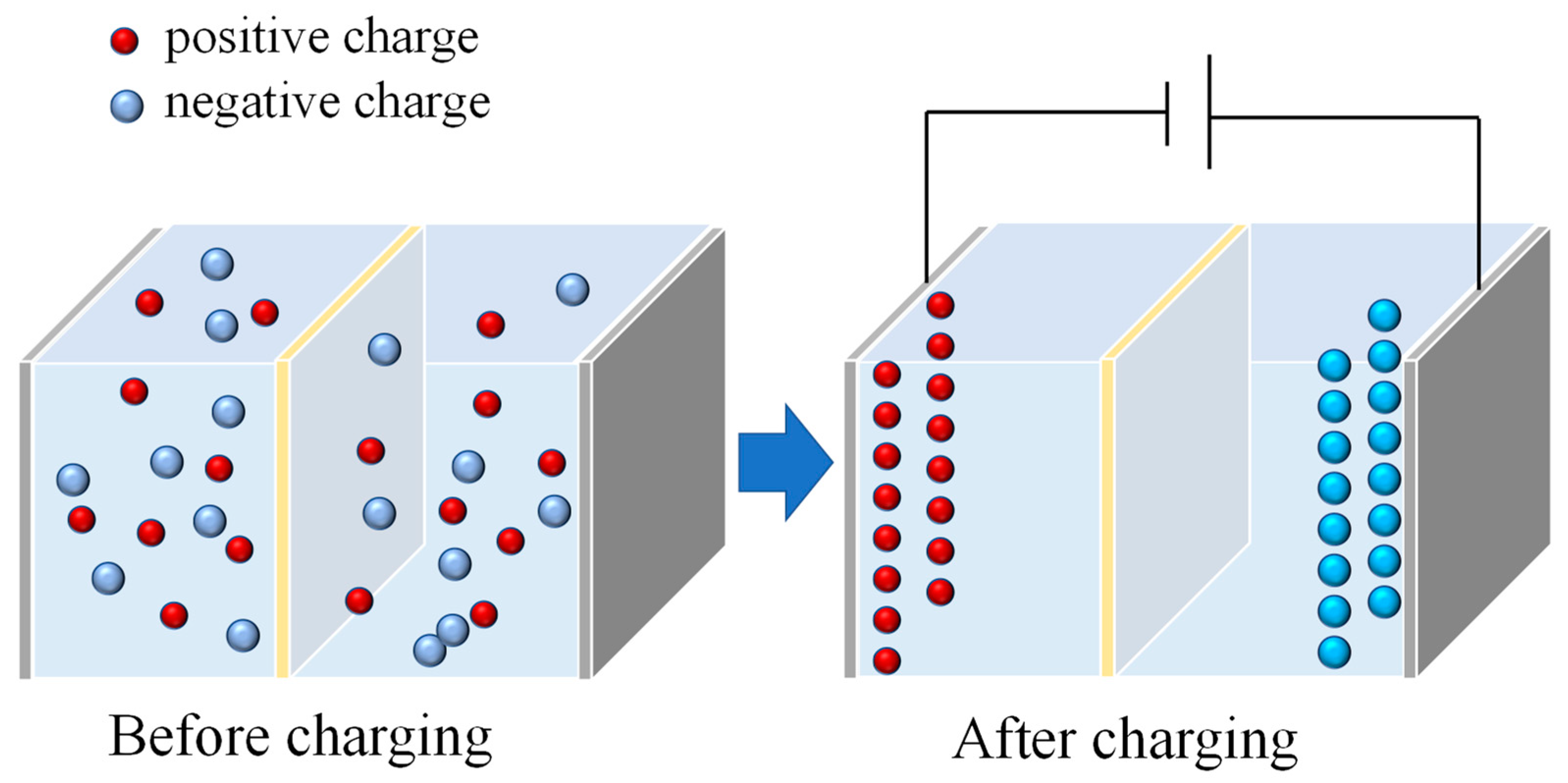
2.1. Working Principle
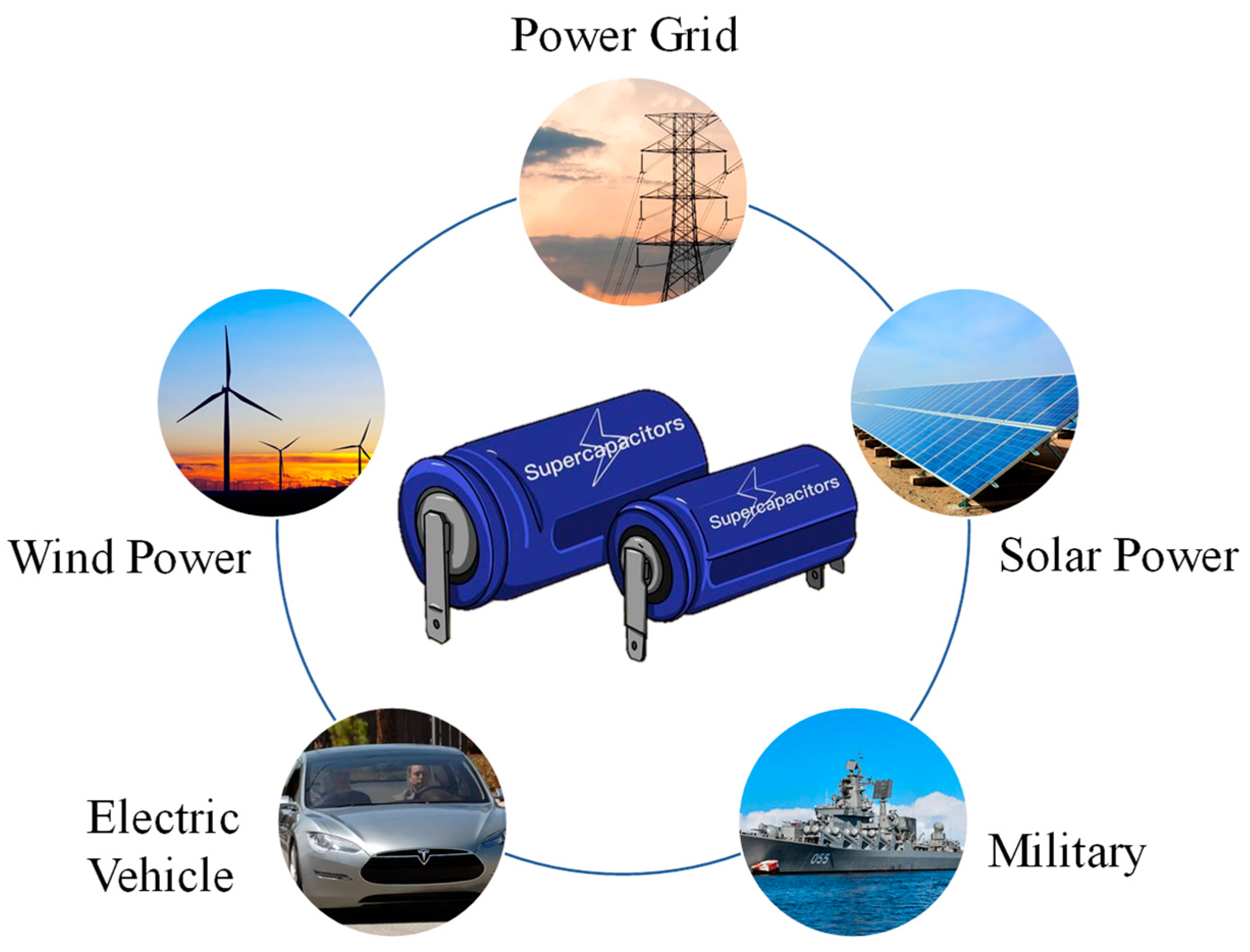
2.2. Applications
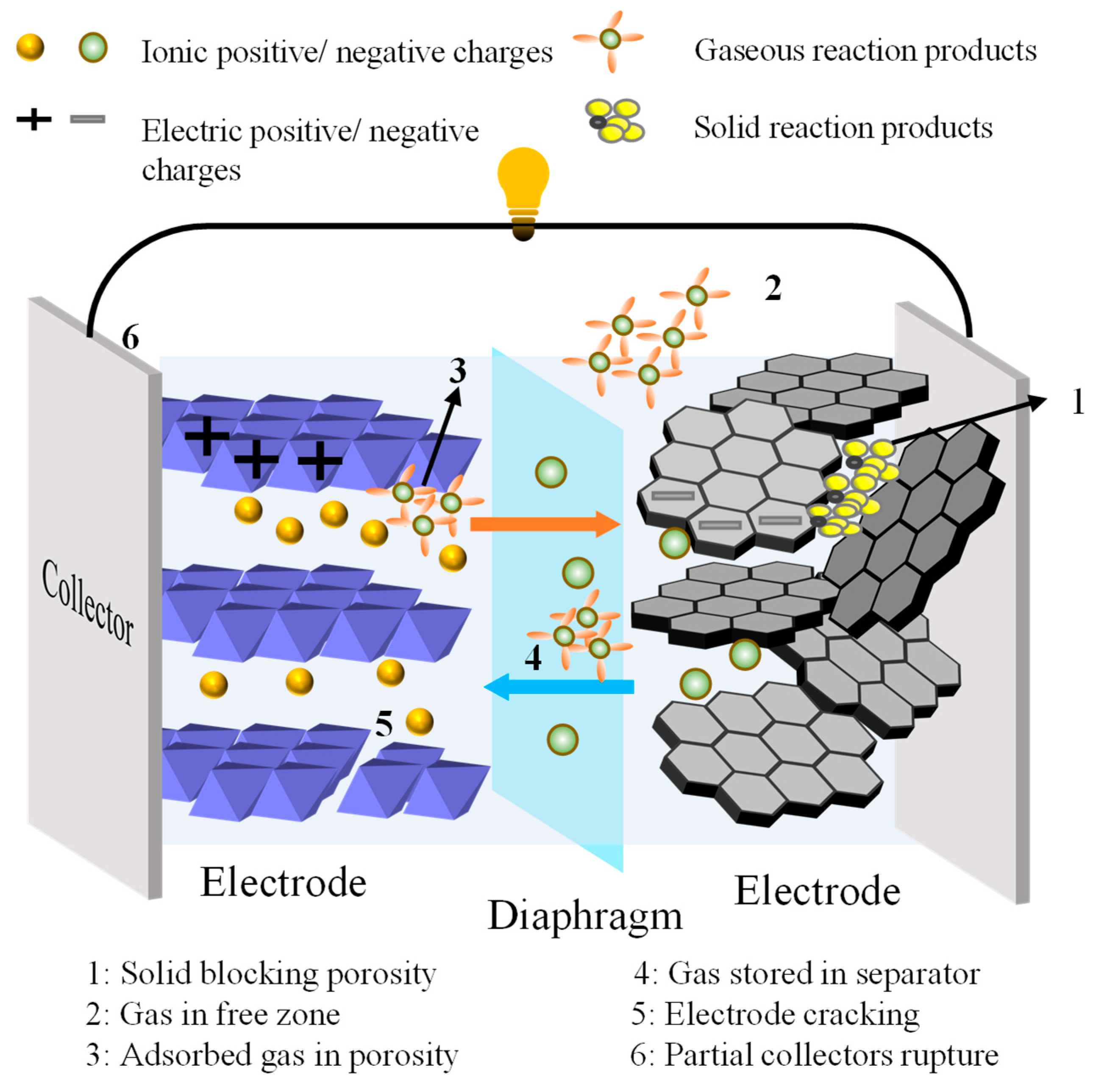
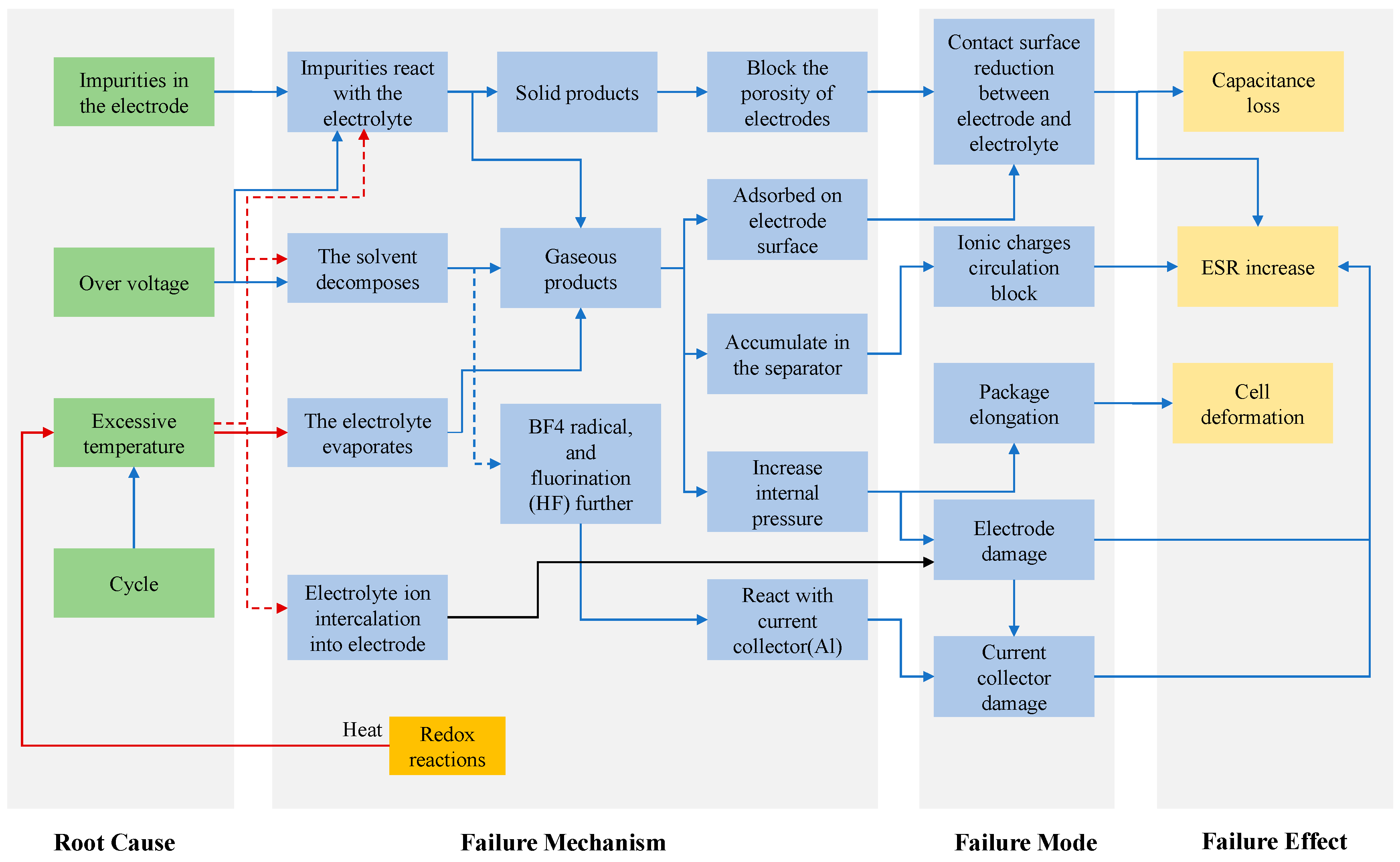
3. Aging Mechanism
3.1. Overview
3.2. Aging Factor
3.2.1. External Stress
3.2.2. Self-Acceleration of Aging
3.2.3. Manufacturing Factors
4. Models
4.1. Equivalent Circuit Models
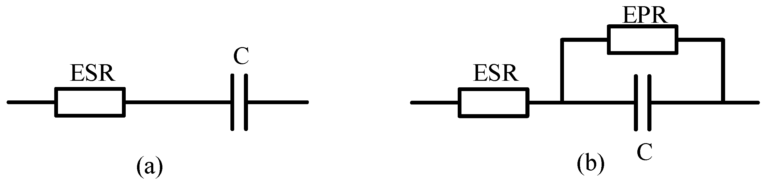
4.1.1. Simple Series RC Models
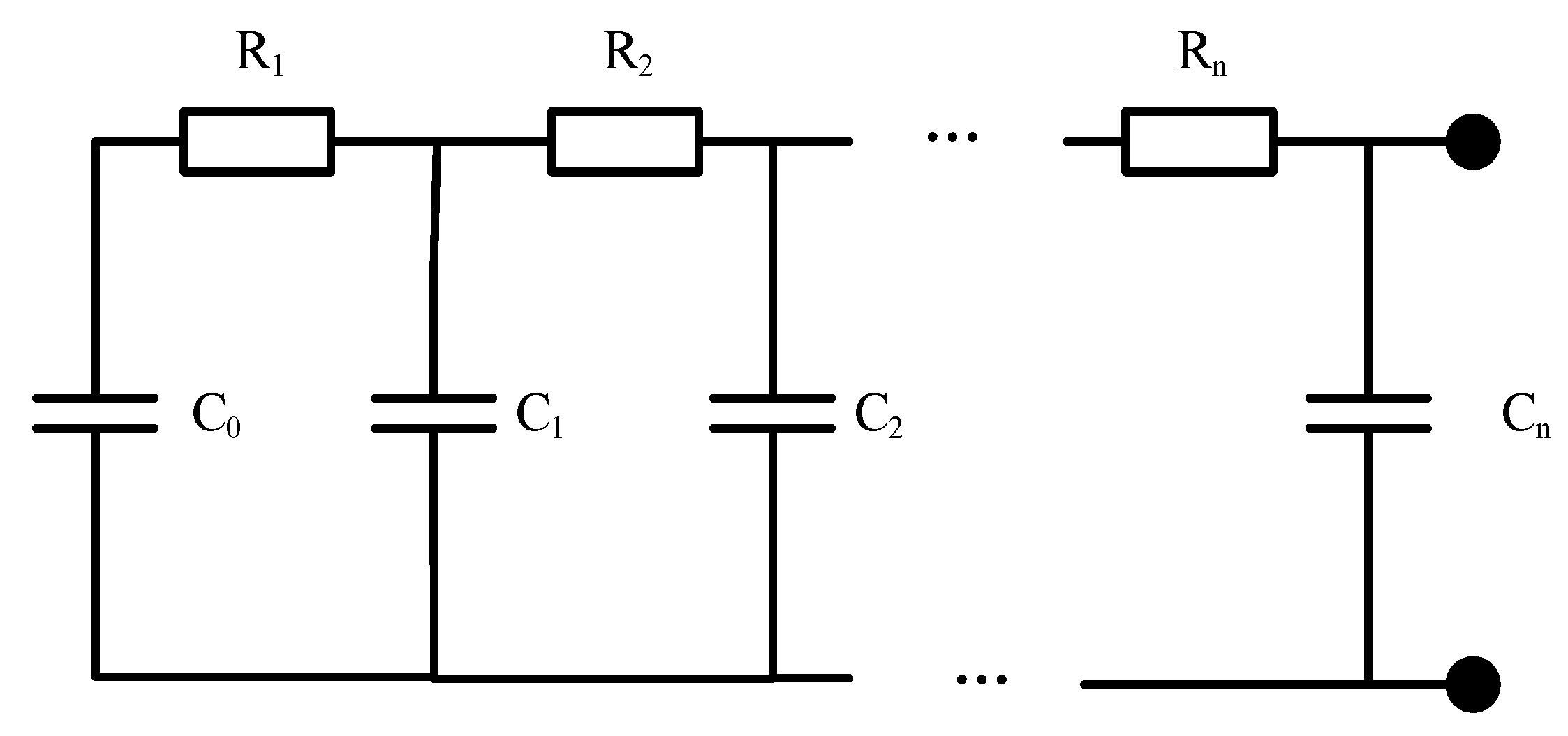
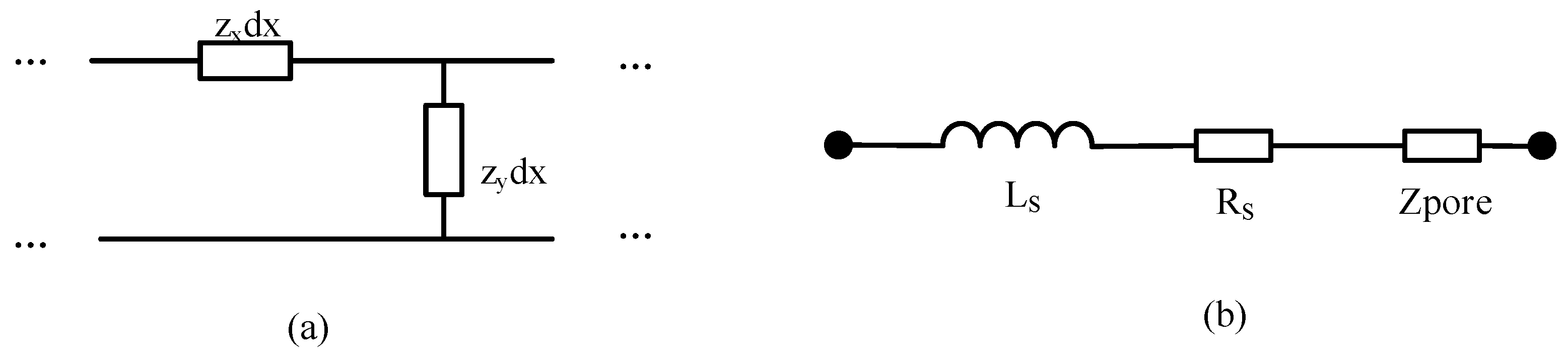
4.1.2. Transmission Line Models
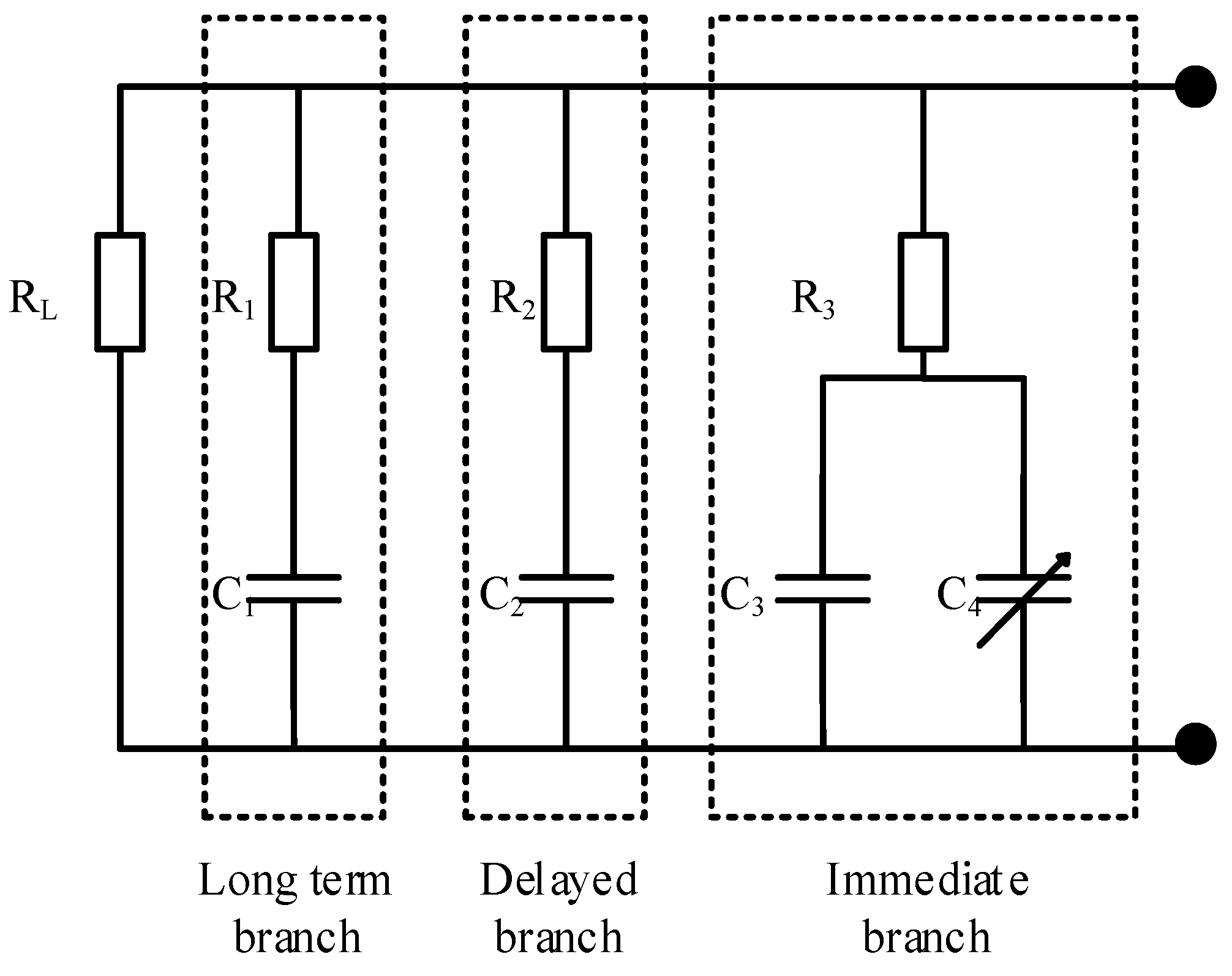
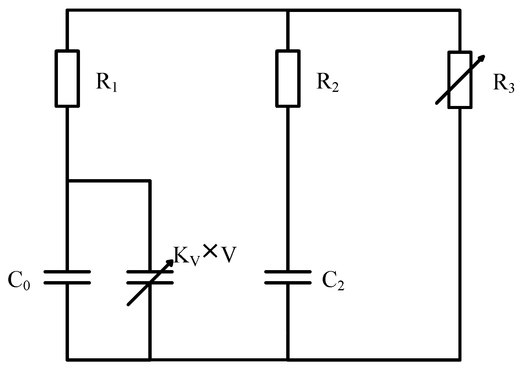
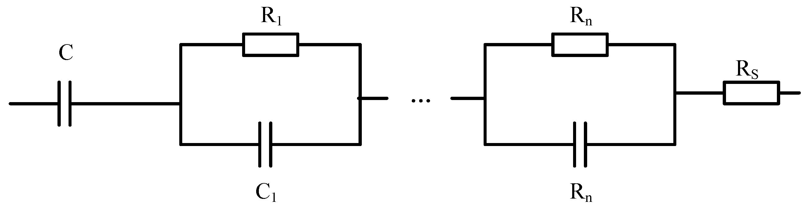
4.1.3. Multi-Branch RC Network Models
4.2. Electrochemical Models
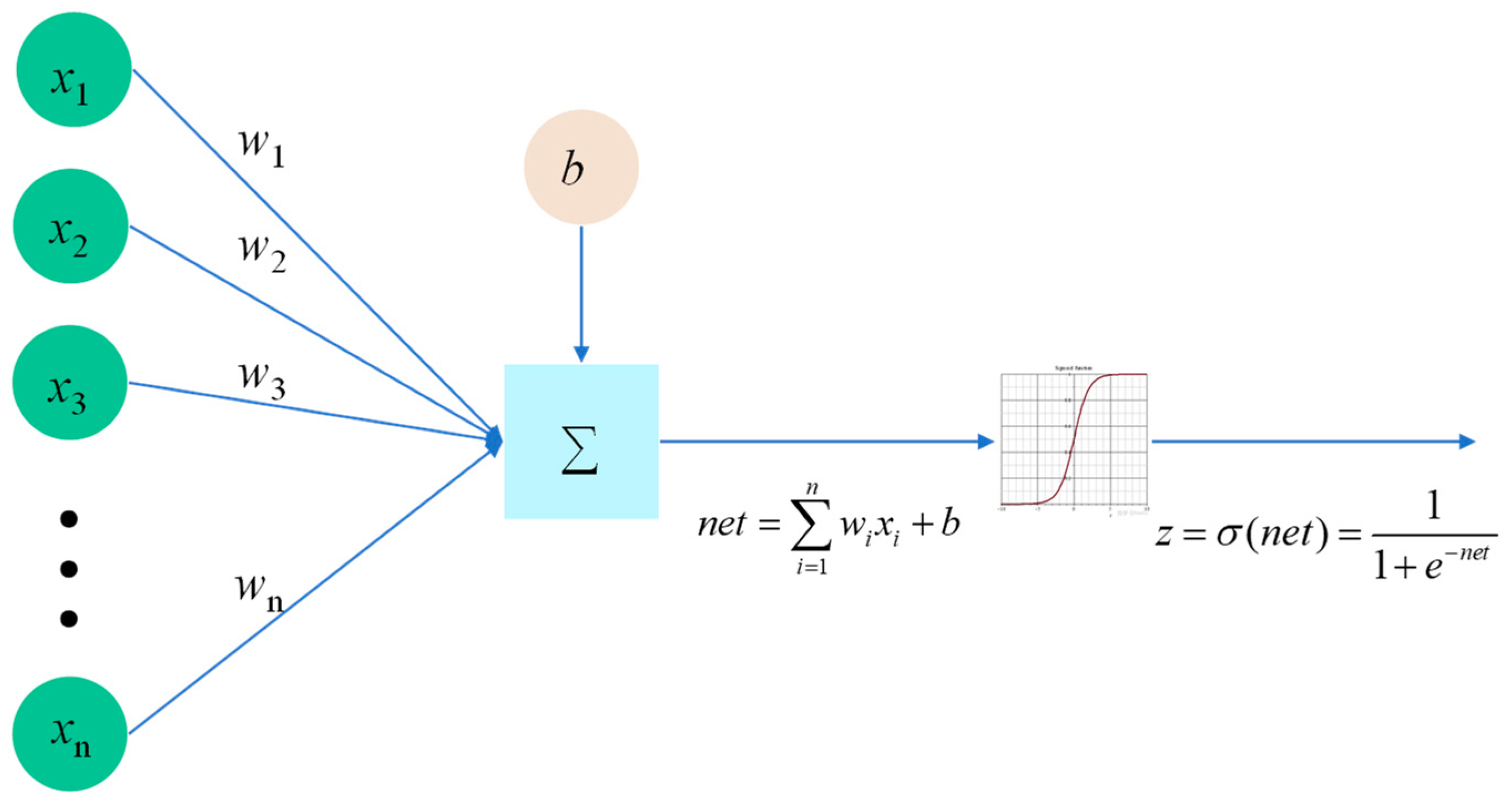
4.3. Intelligent Models
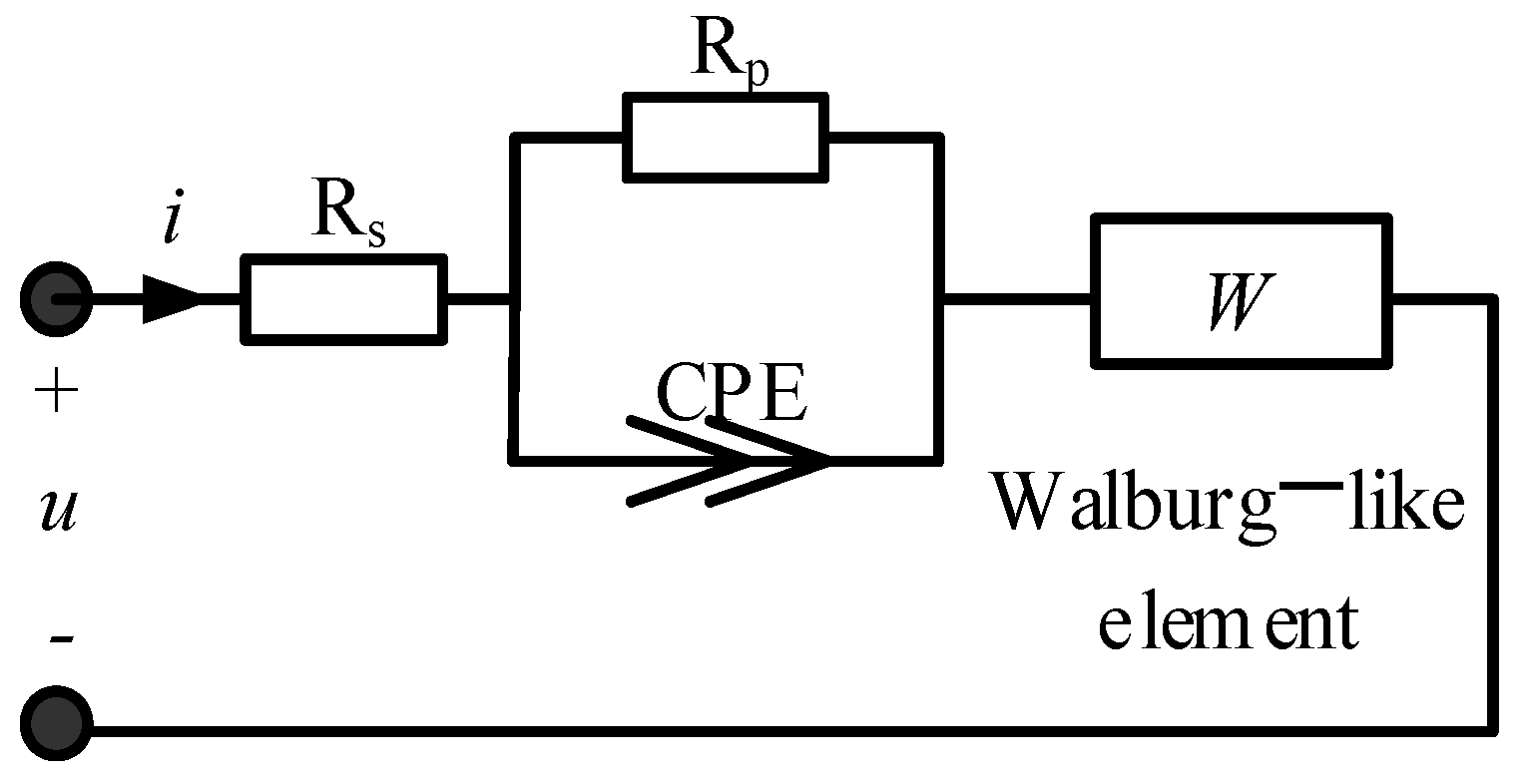
4.4. Fractional-Order Models
4.5. Self-Discharge Models
4.6. Thermal Models
- Heat generation: this kind of model describes the influence of its own heating on its temperature field [20,56,57,58]. The modeling purpose of this kind of model is to analyze the temperature change characteristics and temperature field distribution characteristics of supercapacitors when they work, which is mainly applied to the thermal management analysis of supercapacitor energy storage systems.
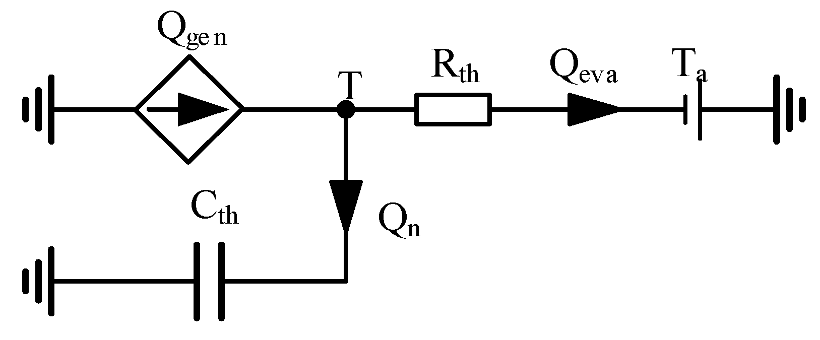
- Heat transmission: this kind of model describes the relationship between temperature and the change in model parameters [55,59]. Its modeling method is usually based on the equivalent circuit model to carry out a large number of experiments, determine the curve of model parameters with temperature, and then establish mathematical expressions through corresponding data processing. This kind of model is of great significance for studying the dynamic characteristics of supercapacitors under different ambient temperatures. The thermal model presented in Ref. [60] is shown in Figure 12. In the model, the heat generation is modeled as a current source, which is a function of the supercapacitor current; Cth represents the thermal capacity of the supercapacitor, Rth denotes the equivalent thermal resistance of the supercapacitor, and Ta denotes the surrounding air temperature.
4.7. Porous Electrode Models
4.8. Dynamic Models of Electrochemical Impedance Spectroscopy
5. Summary and Prospect
- Parameter identification is difficult. At present, AC impedance analysis and circuit analysis are mainly used for supercapacitor model parameters. AC impedance analysis uses a lot of equipment, selects a lot of data when calculating parameters, and the calculation process is complex. The circuit analysis method uses the curve of voltage versus time to obtain the corresponding parameters. This method requires less equipment and is simple and convenient, but the structure of the model itself should not be too complex [66,67,68].
Author Contributions
Funding
Data Availability Statement
Acknowledgments
Conflicts of Interest
References
- Yang, Y.; Han, Y.; Jiang, W.; Zhang, Y.; Xu, Y.; Ahmed, A.M. Application of the Supercapacitor for Energy Storage in China: Role and Strategy. Appl. Sci. 2022, 12, 19. [Google Scholar] [CrossRef]
- Iqbal, M.Z.; Aziz, U. Supercapattery: Merging of battery-supercapacitor electrodes for hybrid energy storage devices. J. Energy Storage 2022, 46, 29. [Google Scholar] [CrossRef]
- Li, Y.; Kong, Y. Energy storage devices based on supercapacitors. Chin. J. Power Sources 2011, 35, 409–411. [Google Scholar]
- Sahin, M.E.; Blaabjerg, F.; Sangwongwanich, A. A Comprehensive Review on Supercapacitor Applications and Developments. Energies 2022, 15, 674. [Google Scholar] [CrossRef]
- Ma, Y.; Xie, X.; Yang, W.; Yu, Z.; Sun, X.; Zhang, Y.; Yang, X.; Kimura, H.; Hou, C.; Guo, Z.; et al. Recent advances in transition metal oxides with different dimensions as electrodes for high-performance supercapacitors. Adv. Compos. Hybrid Mater. 2021, 4, 906–924. [Google Scholar] [CrossRef]
- Chatterjee, D.P.; Nandi, A.K. A review on the recent advances in hybrid supercapacitors. J. Mater. Chem. A 2021, 9, 15880–15918. [Google Scholar] [CrossRef]
- Chen, Y.; He, Y.G.; Li, Z.; Chen, L.P. A Combined Multiple Factor Degradation Model and Online Verification for Electric Vehicle Batteries. Energies 2019, 12, 12. [Google Scholar] [CrossRef] [Green Version]
- Laadjal, K.; Cardoso AJ, M. A review of supercapacitors modeling, SoH, and SoE estimation methods: Issues and challenges. Int. J. Energy Res. 2021, 45, 18424–18440. [Google Scholar] [CrossRef]
- Yang, H. A review of supercapacitor-based energy storage systems for microgrid applications. In Proceedings of the 2018 IEEE Power & Energy Society General Meeting (PESGM), Portland, OR, USA, 5–9 August 2018; pp. 1–5. [Google Scholar]
- Zhang, L.; Hu, X.S.; Wang, Z.P.; Ruan, J.G.; Ma, C.B.; Song, Z.Y.; Dorrell, D.G.; Pecht, M.G. Hybrid electrochemical energy storage systems: An overview for smart grid and electrified vehicle applications. Renew. Sustain. Energy Rev. 2021, 13, 1105819. [Google Scholar] [CrossRef]
- Wang, K.; Ren, B.S.; Li, L.W.; Li, Y.H.; Zhang, H.W.; Sui, Z.Q. A review of Modeling Research on Supercapacitor. In Proceedings of the Chinese Automation Congress (CAC), Jinan, China, 20–22 October 2017; pp. 5998–6001. [Google Scholar]
- Huang, X.; Zhang, X.; Wei, T.; Qi, Z.; Ma, Y. Development and applications status of supercapacitors. Adv. Technol. Electr. Eng. Energy 2017, 36, 63–70. [Google Scholar]
- Wu, J.; Zhou, Z.; Zha, F.; He, T.; Feng, B. Supercapacitor and their applications in power grids. Chin. J. Power Sources 2016, 40, 2095–2097. [Google Scholar]
- Zhai, C.; Luo, F.; Liu, Y. Cooperative Power Split Optimization for a Group of Intelligent Electric Vehicles Travelling on a Highway with Varying Slopes. IEEE Trans. Intell. Transp. Syst. 2022, 23, 4993–5005. [Google Scholar] [CrossRef]
- Wang, Y.F.; Zhang, L.; Hou, H.Q.; Xu, W.H.; Duan, G.G.; He, S.J.; Liu, K.M.; Jiang, S.H. Recent progress in carbon-based materials for supercapacitor electrodes: A review. J. Mater. Sci. 2021, 56, 173–200. [Google Scholar] [CrossRef]
- Azais, P.; Duclaux, L.; Florian, P.; Massiot, D.; Lillo-Rodenas, M.A.; Linares-Solano, A.; Peres, J.P.; Jehoulet, C.; Beguin, F. Causes of supercapacitors ageing in organic electrolyte. J. Power Sources 2007, 171, 1046–1053. [Google Scholar] [CrossRef]
- Li, D.; Li, S.; Zhang, S.; Sun, J.; Wang, L.; Wang, K. Aging state prediction for supercapacitors based on heuristic kalman filter optimization extreme learning machine. Energy 2022, 250, 123773. [Google Scholar] [CrossRef]
- Liu, S.; Wei, L.; Wang, H. Review on reliability of supercapacitors in energy storage applications. Appl. Energy 2020, 278, 13. [Google Scholar] [CrossRef]
- Ayadi, M.; Briat, B.; Lallemand, R.; Eddahech, A.; German, R.; Coquery, G.; Vinassa, J.M. Description of supercapacitor performance degradation rate during thermal cycling under constant voltage ageing test. Microelectron. Reliab. 2014, 54, 1944–1948. [Google Scholar] [CrossRef]
- Bohlen, O.; Kowal, J.; Sauer, D.U. Ageing behaviour of electrochemical double layer capacitors—Part II. Lifetime simulation model for dynamic applications. J. Power Sources 2007, 173, 626–632. [Google Scholar] [CrossRef]
- Zheng, F.H.; Li, Y.X.; Wang, X.S. Study on effects of applied current and voltage on the ageing of supercapacitors. Electrochim. Acta 2018, 276, 343–351. [Google Scholar] [CrossRef]
- Sedlakova, V.; Sikula, J.; Majzner, J.; Sedlak, P.; Kuparowitz, T.; Buergler, B.; Vasina, P. Supercapacitor degradation assesment by power cycling and calendar life tests. Metrol. Meas. Syst. 2016, 23, 345–358. [Google Scholar] [CrossRef] [Green Version]
- Zhang, L.; Hu, X.S.; Wang, Z.P.; Sun, F.C.; Dorrell, D.G. A review of supercapacitor modeling, estimation, and applications: A control/management perspective. Renew. Sustain. Energy Rev. 2018, 81, 1868–1878. [Google Scholar] [CrossRef]
- Kim, S.-H.; Choi, W.; Lee, K.-B.; Choi, S. Advanced Dynamic Simulation of Supercapacitors Considering Parameter Variation and Self-Discharge. IEEE Trans. Power Electron. 2011, 26, 3377–3385. [Google Scholar]
- Eddahech, A.; Ayadi, M.; Briat, O.; Vinassa, J.-M. Online parameter identification for real-time supercapacitor performance estimation in automotive applications. Int. J. Electr. Power Energy Syst. 2013, 51, 162–167. [Google Scholar] [CrossRef]
- Berrueta, A.; Ursua, A.; San Martin, I.; Eftekhari, A.; Sanchis, P. Supercapacitors: Electrical Characteristics, Modeling, Applications, and Future Trends. IEEE Access 2019, 7, 50869–50896. [Google Scholar] [CrossRef]
- Spyker, R.L.; Nelms, R.M. Classical equivalent circuit parameters for a double-layer capacitor. IEEE Trans. Aerosp. Electron. Syst. 2000, 36, 829–836. [Google Scholar] [CrossRef]
- Pean, C.; Rotenberg, B.; Simon, P.; Salanne, M. Multi-scale modelling of supercapacitors: From molecular simulations to a transmission line model. J. Power Sources 2016, 326, 680–685. [Google Scholar] [CrossRef] [Green Version]
- Torregrossa, D.; Bahramipanah, M.; Namor, E.; Cherkaoui, R.; Paolone, M. Improvement of Dynamic Modeling of Supercapacitor by Residual Charge Effect Estimation. IEEE Trans. Ind. Electron. 2014, 61, 1345–1354. [Google Scholar] [CrossRef]
- Moayedi, S.; Cingoz, F.; Davoudi, A. Accelerated Simulation of High-Fidelity Models of Supercapacitors Using Waveform Relaxation Techniques. IEEE Trans. Power Electron. 2013, 28, 4903–4909. [Google Scholar] [CrossRef]
- Logerais, P.O.; Camara, M.A.; Riou, O.; Djellad, A.; Omeiri, A.; Delaleux, F.; Durastanti, J.F. Modeling of a supercapacitor with a multibranch circuit. Int. J. Hydrogen Energy 2015, 40, 13725–13736. [Google Scholar] [CrossRef]
- Saha, P.; Dey, S.; Khanra, M. Modeling and State-of-Charge Estimation of Supercapacitor Considering Leakage Effect. IEEE Trans. Ind. Electron. 2020, 67, 350–357. [Google Scholar] [CrossRef]
- Zubieta, L.; Bonert, R. Characterization of double-layer capacitors for power electronics applications. IEEE Trans. Ind. Appl. 2000, 36, 199–205. [Google Scholar] [CrossRef] [Green Version]
- Rajani, S.V.; Pandya, V.J.; Shah, V.A. Experimental validation of the ultracapacitor parameters using the method of averaging for photovoltaic applications. J. Energy Storage 2016, 5, 120–126. [Google Scholar] [CrossRef]
- Faranda, R. A new parameters identification procedure for simplified double layer capacitor two-branch model. Electr. Power Syst. Res. 2010, 80, 363–371. [Google Scholar] [CrossRef]
- Chai, R.Z.; Zhang, Y. A Practical Supercapacitor Model for Power Management in Wireless Sensor Nodes. IEEE Trans. Power Electron. 2015, 30, 6720–6730. [Google Scholar] [CrossRef]
- Weddell, A.S.; Merrett, G.V.; Kazmierski, T.J.; Al-Hashimi, B.M. Accurate Supercapacitor Modeling for Energy Harvesting Wireless Sensor Nodes. IEEE Trans. Circuits Syst. Ii-Express Briefs 2011, 58, 911–915. [Google Scholar] [CrossRef] [Green Version]
- Helmholtz, H.V. Studien über electrische Grenzschichten. Ann. Phys. 1879, 243, 337–382. [Google Scholar] [CrossRef] [Green Version]
- Guoy, G. Constitution of the electric charge at the surface of an electrolyte. J. Phys. 1910, 9, 457–467. [Google Scholar]
- Chapman DL, L.I. A contribution to the theory of electrocapillarity. Lond. Edinb. Dublin Philos. Mag. J. Sci. 1913, 25, 475–481. [Google Scholar] [CrossRef] [Green Version]
- Yu, A.; Chabot, V.; Zhang, J. Electrochemical Supercapacitors for Energy Storage and Delivery: Fundamentals and Applications; Taylor & Francis: Abingdon, UK, 2013. [Google Scholar]
- Eziani, S.; Ouassaid, M. State of Charge Estimation of Supercapacitor Using Artificial Neural Network for Onboard Railway Applications. In Proceedings of the 6th International Renewable and Sustainable Energy Conference (IRSEC), Rabat, Morocco, 5–8 December 2018; pp. 1076–1081. [Google Scholar]
- Liu, C.L.; Zhang, Y.; Sun, J.R.; Cui, Z.H.; Wang, K. Stacked bidirectional LSTM RNN to evaluate the remaining useful life of supercapacitor. Int. J. Energy Res. 2022, 46, 3034–3043. [Google Scholar] [CrossRef]
- Westerlund, S.; Ekstam, L. Capacitor theory. IEEE Trans. Dielectr. Electr. Insul. 1994, 1, 826–839. [Google Scholar] [CrossRef]
- Zhang, L.; Hu, X.S.; Wang, Z.P.; Sun, F.C.; Dorrell, D.G. Fractional-order modeling and State-of-Charge estimation for ultracapacitors. J. Power Sources 2016, 314, 28–34. [Google Scholar] [CrossRef]
- Zou, C.; Zhang, L.; Hu, X.; Wang, Z.; Wik, T.; Pecht, M. A review of fractional-order techniques applied to lithium-ion batteries, lead-acid batteries, and supercapacitors. J. Power Sources 2018, 390, 286–296. [Google Scholar] [CrossRef] [Green Version]
- Freeborn, T.J. Estimating supercapacitor performance for embedded applications using fractional-order models. Electron. Lett. 2016, 52, 1478–1479. [Google Scholar] [CrossRef]
- Dzielinski, A.; Sierociuk, D. Ultracapacitor modelling and control using discrete fractional order state-space model. Acta Montan. Slovaca 2008, 13, 136–145. [Google Scholar]
- Smith, P.H.; Tran, T.N.; Jiang, T.L.; Chung, J. Lithium-ion capacitors: Electrochemical performance and thermal behavior. J. Power Sources 2013, 243, 982–992. [Google Scholar] [CrossRef]
- Conway, B.E.; Pell, W.; Liu, T. Diagnostic analyses for mechanisms of self-discharge of electrochemical capacitors and batteries. J. Power Sources 1997, 65, 53–59. [Google Scholar] [CrossRef]
- Yang, H.Z.; Zhang, Y. Self-discharge analysis and characterization of supercapacitors for environmentally powered wireless sensor network applications. J. Power Sources 2011, 196, 8866–8873. [Google Scholar] [CrossRef]
- Ricketts, B.W.; Ton-That, C. Self-discharge of carbon-based supercapacitors with organic electrolytes. J. Power Sources 2000, 89, 64–69. [Google Scholar] [CrossRef]
- Oickle, A.M.; Andreas, H.A. Examination of water electrolysis and oxygen reduction as self-discharge mechanisms for carbon-based, aqueous electrolyte electrochemical capacitors. J. Phys. Chem. C 2011, 115, 4283–4288. [Google Scholar] [CrossRef]
- Gualous, H.; Bouquain, D.; Berthon, A.; Kauffmann, J.M. Experimental study of supercapacitor serial resistance and capacitance variations with temperature. J. Power Sources 2003, 123, 86–93. [Google Scholar] [CrossRef]
- Guillemet, P.; Scudeller, Y.; Brousse, T. Multi-level reduced-order thermal modeling of electrochemical capacitors. J. Power Sources 2006, 157, 630–640. [Google Scholar] [CrossRef]
- Lee, D.H.; Kim, U.S.; Shin, C.B.; Lee, B.H.; Kim, B.W.; Kim, Y.-H. Modelling of the thermal behaviour of an ultracapacitor for a 42-V automotive electrical system. J. Power Sources 2008, 175, 664–668. [Google Scholar] [CrossRef]
- Guillemet, P.; Pascot, C.; Scudeller, Y. Compact Thermal Modeling of Electric Double-Layer-Capacitors. In Proceedings of the 14th International Workshop on Thermal Investigations of ICs and Systems, Rome, Italy, 24–26 September 2008; pp. 118–122. [Google Scholar]
- Kötz, R.; Hahn, M.; Gallay, R. Temperature behavior and impedance fundamentals of supercapacitors. J. Power Sources 2006, 154, 550–555. [Google Scholar] [CrossRef]
- Hijazi, A.; Kreczanik, P.; Bideaux, E.; Venet, P.; Clerc, G.; Di Loreto, M. Thermal Network Model of Supercapacitors Stack. IEEE Trans. Ind. Electron. 2012, 59, 979–987. [Google Scholar] [CrossRef]
- Wang, K.; Zhang, L.; Ji, B.; Yuan, J. The thermal analysis on the stackable supercapacitor. Energy 2013, 59, 440–444. [Google Scholar] [CrossRef]
- Buller, S.; Karden, E.; Kok, D.; De Doncker, R.W. Modeling the dynamic behavior of supercapacitors using impedance spectroscopy. IEEE Trans. Ind. Appl. 2002, 38, 1622–1626. [Google Scholar] [CrossRef]
- Huang, S.F.; Zhu, X.L.; Sarkar, S.; Zhao, Y.F. Challenges and opportunities for supercapacitors. APL Mater. 2019, 7, 9. [Google Scholar] [CrossRef] [Green Version]
- Wang, R.; Yao, M.J.; Niu, Z.Q. Smart supercapacitors from materials to devices. Infomat 2020, 2, 113–125. [Google Scholar] [CrossRef] [Green Version]
- Lokhande, P.E.; Chavan, U.S.; Pandey, A. Materials and Fabrication Methods for Electrochemical Supercapacitors: Overview. Electrochem. Energy Rev. 2020, 3, 155–186. [Google Scholar] [CrossRef]
- Wang, F.X.; Wu, X.W.; Yuan, X.H.; Liu, Z.C.; Zhang, Y.; Fu, L.J.; Zhu, Y.S.; Zhou, Q.M.; Wu, Y.P.; Huang, W. Latest advances in supercapacitors: From new electrode materials to novel device designs. Chem. Soc. Rev. 2017, 46, 6816–6854. [Google Scholar] [CrossRef]
- Chen, X.; Paul, R.; Dai, L. Carbon-based supercapacitors for efficient energy storage. Natl. Sci. Rev. 2017, 4, 453–489. [Google Scholar] [CrossRef] [Green Version]
- Meng, Q.; Cai, K.; Chen, Y.; Chen, L. Research progress on conducting polymer based supercapacitor electrode materials. Nano Energy 2017, 36, 268–285. [Google Scholar] [CrossRef]
- Yedluri, A.K.; Kim, H.-J. Wearable super-high specific performance supercapacitors using a honeycomb with folded silk-like composite of NiCo 2 O 4 nanoplates decorated with NiMoO 4 honeycombs on nickel foam. Dalton Trans. 2018, 47, 15545–15554. [Google Scholar] [CrossRef] [PubMed]
- Kulurumotlakatla, D.K.; Yedluri, A.K.; Kim, H.-J. Hierarchical NiCo2S4 nanostructure as highly efficient electrode material for high-performance supercapacitor applications. J. Energy Storage 2020, 31, 101619. [Google Scholar] [CrossRef]
- Kumar, Y.A.; Kim, H.-J. Preparation and electrochemical performance of NiCo2 O4@ NiCo2 O4 composite nanoplates for high performance supercapacitor applications. New J. Chem. 2018, 42, 19971–19978. [Google Scholar] [CrossRef]
- Guo, Y.; Yang, D.; Zhang, Y.; Wang, L.; Wang, K. Online estimation of SOH for lithium-ion battery based on SSA-Elman neural network. Prot. Control. Mod. Power Syst. 2022, 7, 40. [Google Scholar] [CrossRef]
- Zhang, M.; Liu, Y.; Li, D.; Cui, X.; Wang, L.; Li, L.; Wang, K. Electrochemical Impedance Spectroscopy: A New Chapter in the Fast and Accurate Estimation of the State of Health for Lithium-Ion Batteries. Energies 2023, 16, 1599. [Google Scholar] [CrossRef]
- Wang, L.; Xie, L.; Yang, Y.; Zhang, Y.; Wang, K.; Cheng, S.-j. Distributed Online Voltage Control with Fast PV Power Fluctuations and Imperfect Communication. IEEE Trans. Smart Grid 2023. [Google Scholar] [CrossRef]
- Zhang, M.; Wang, W.; Xia, G.; Wang, L.; Wang, K. Self-Powered Electronic Skin for Remote Human–Machine Synchronization. ACS Appl. Electron. Mater. 2023, 5, 498–508. [Google Scholar] [CrossRef]


| Models | Advantages | Disadvantages |
|---|---|---|
| Equivalent circuit models | Simple and intuitive; convenient for analysis, calculation, and simulation; moderate accuracy | Susceptible to aging process |
| Electrochemical models | Description of inside physical–chemical reactions; high possible accuracy | Cannot reflect the dynamic process of charging and discharging; heavy computation; immeasurability of some parameters |
| Intelligent models | Can approximate the nonlinear characteristics of the system; good modeling capability | Absence of physical meanings; sensitive to training data quality and quantity; poor robustness |
| Fractional-order models | Better capability to fitting experimental data; few model parameters | Heavy computation |
Disclaimer/Publisher’s Note: The statements, opinions and data contained in all publications are solely those of the individual author(s) and contributor(s) and not of MDPI and/or the editor(s). MDPI and/or the editor(s) disclaim responsibility for any injury to people or property resulting from any ideas, methods, instructions or products referred to in the content. |
© 2023 by the authors. Licensee MDPI, Basel, Switzerland. This article is an open access article distributed under the terms and conditions of the Creative Commons Attribution (CC BY) license (https://creativecommons.org/licenses/by/4.0/).
Share and Cite
Ma, N.; Yang, D.; Riaz, S.; Wang, L.; Wang, K. Aging Mechanism and Models of Supercapacitors: A Review. Technologies 2023, 11, 38. https://doi.org/10.3390/technologies11020038
Ma N, Yang D, Riaz S, Wang L, Wang K. Aging Mechanism and Models of Supercapacitors: A Review. Technologies. 2023; 11(2):38. https://doi.org/10.3390/technologies11020038
Chicago/Turabian StyleMa, Ning, Dongfang Yang, Saleem Riaz, Licheng Wang, and Kai Wang. 2023. "Aging Mechanism and Models of Supercapacitors: A Review" Technologies 11, no. 2: 38. https://doi.org/10.3390/technologies11020038