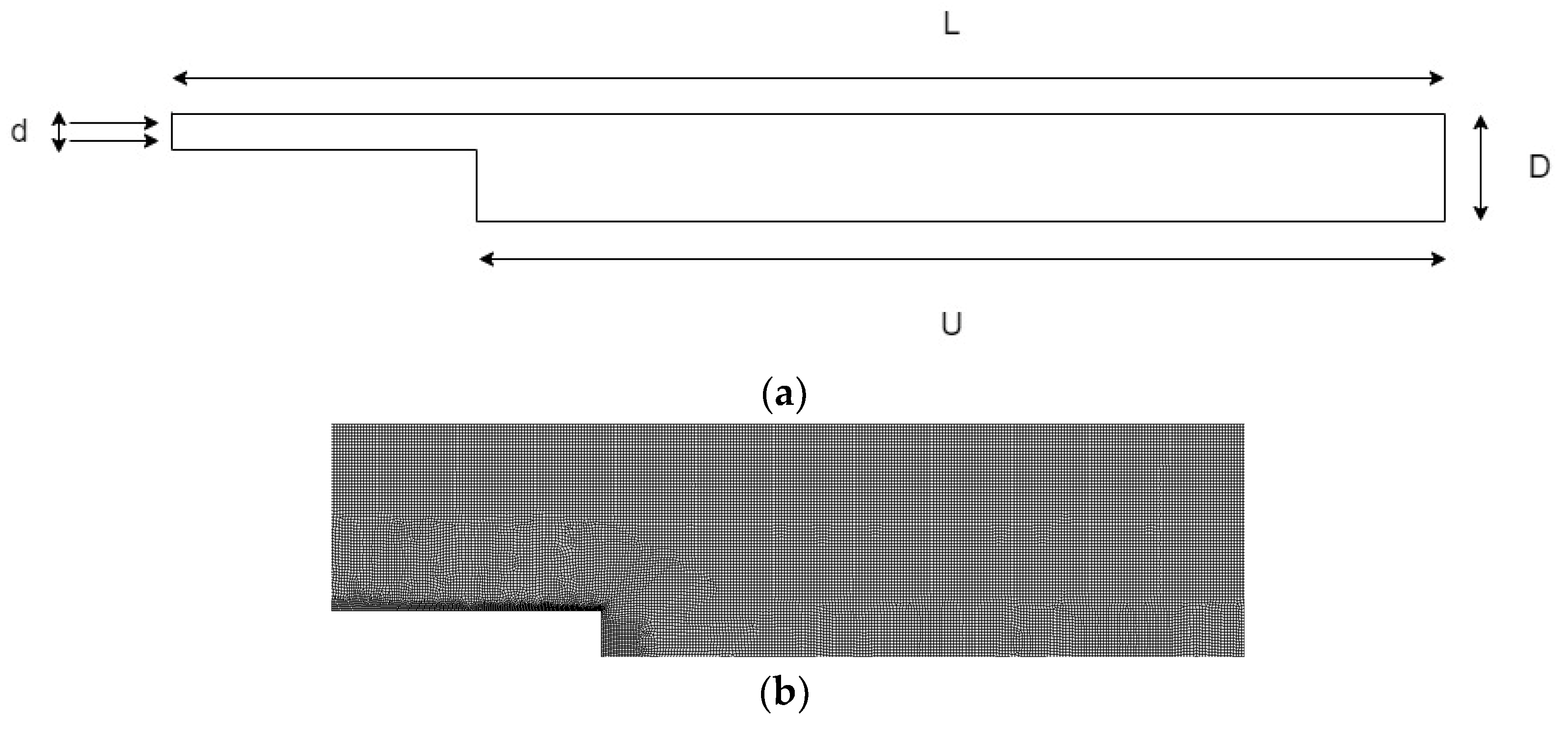
Figure 1.
(a) Problem geometry; (b) computational mesh for ER—1.9432; (b) zoomed out computational mesh.
Figure 1.
(a) Problem geometry; (b) computational mesh for ER—1.9432; (b) zoomed out computational mesh.
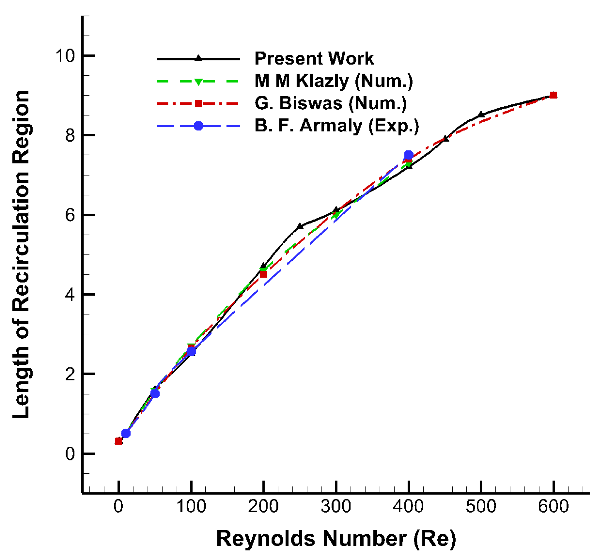
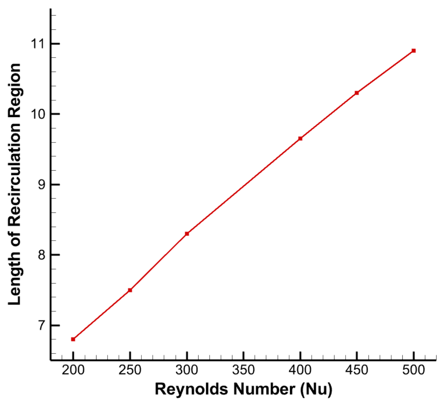
Figure 2.
Length of the primary recirculation region behind backward facing step having an expansion ratio of 1.9423 for flow of water compared with Armaly [
6], Biswas [
7] and Klazly [
71].
Figure 2.
Length of the primary recirculation region behind backward facing step having an expansion ratio of 1.9423 for flow of water compared with Armaly [
6], Biswas [
7] and Klazly [
71].
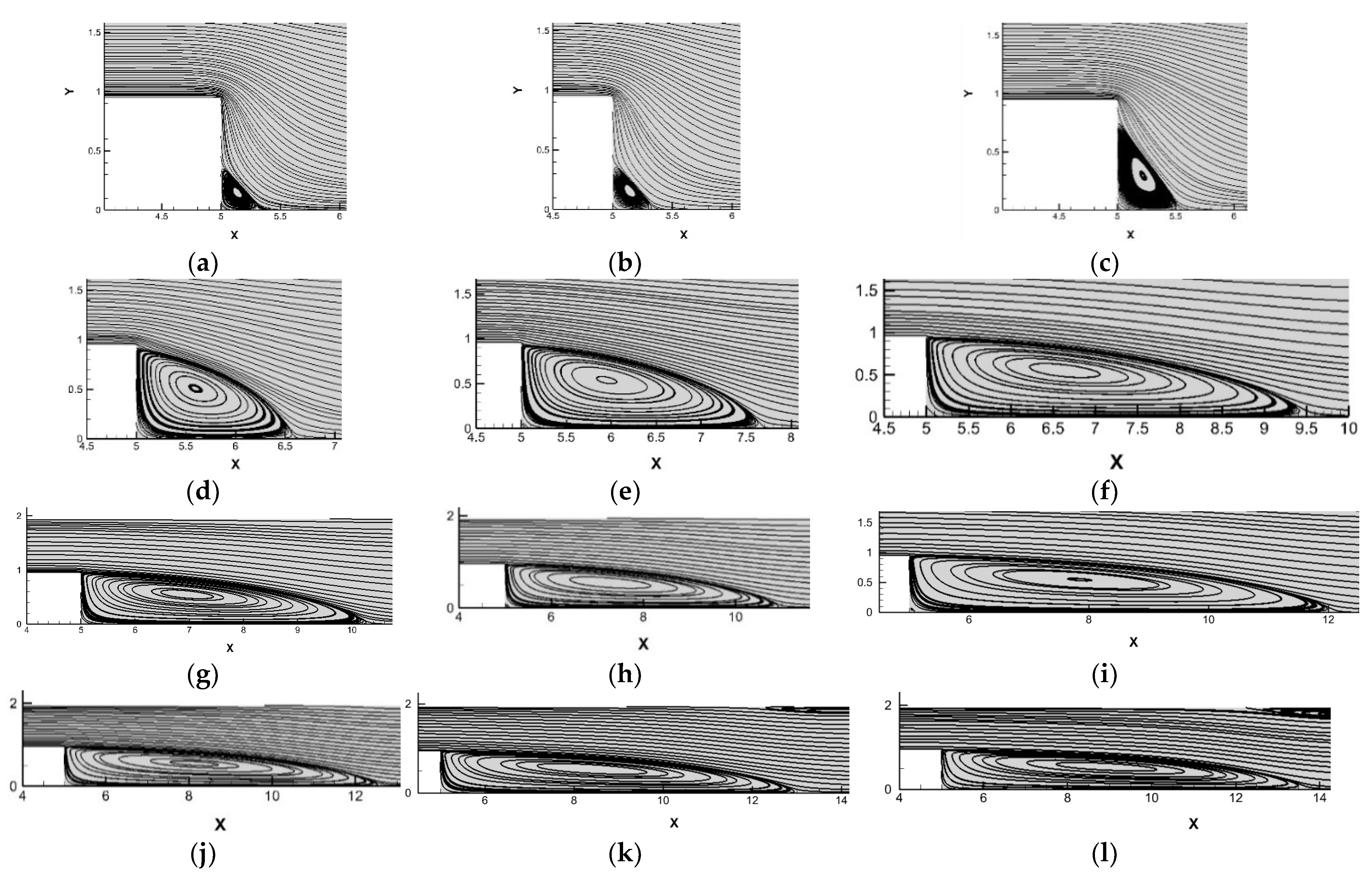
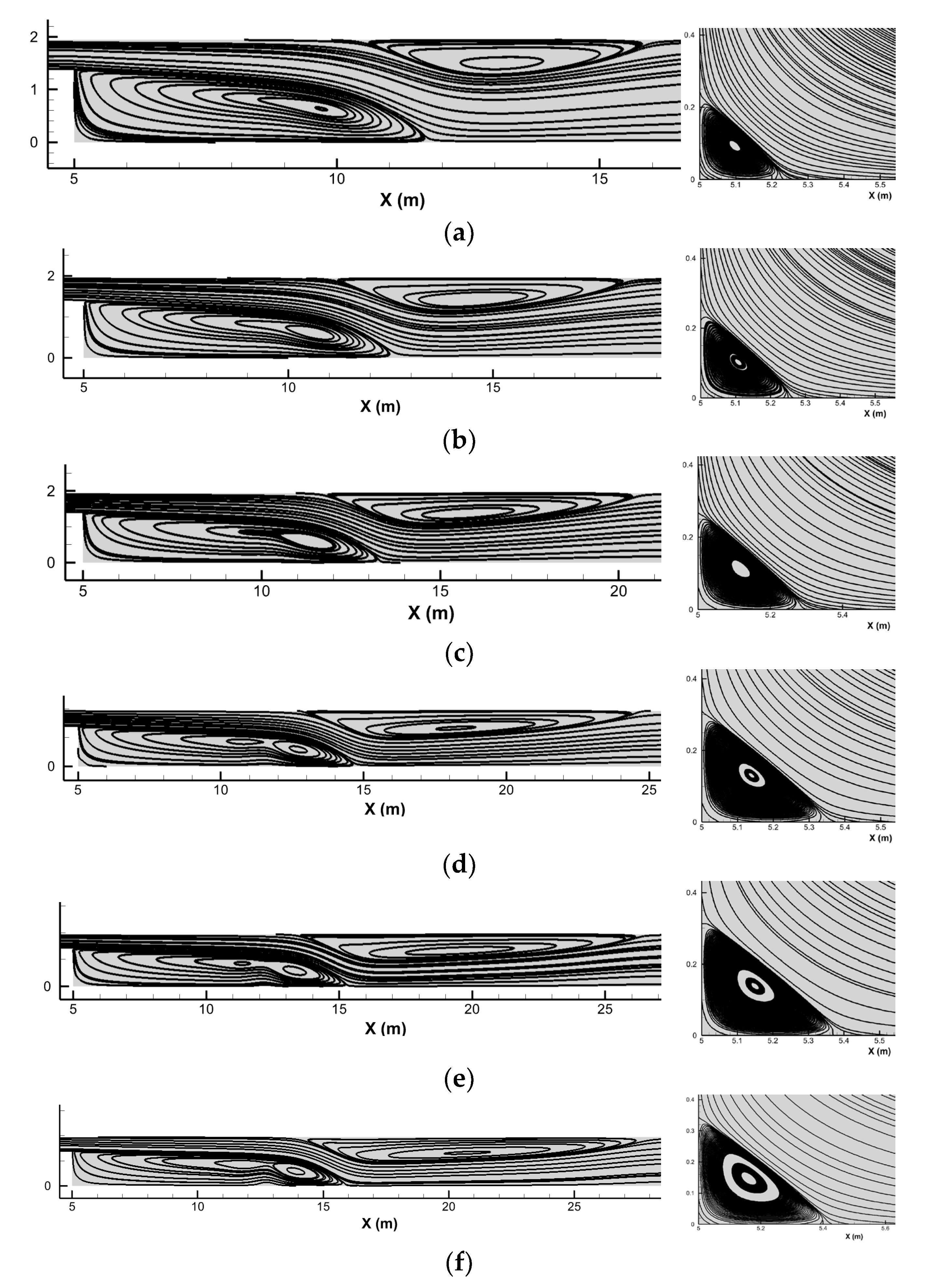
Figure 3.
Streamlines near the backward facing step for flow of water at various Reynolds number: (a) 0.1, (b) 1, (c) 10, (d) 50, (e) 100, (f) 200, (g) 250, (h) 300, (i) 400, (j) 450, (k) 500, and (l) 600.
Figure 3.
Streamlines near the backward facing step for flow of water at various Reynolds number: (a) 0.1, (b) 1, (c) 10, (d) 50, (e) 100, (f) 200, (g) 250, (h) 300, (i) 400, (j) 450, (k) 500, and (l) 600.
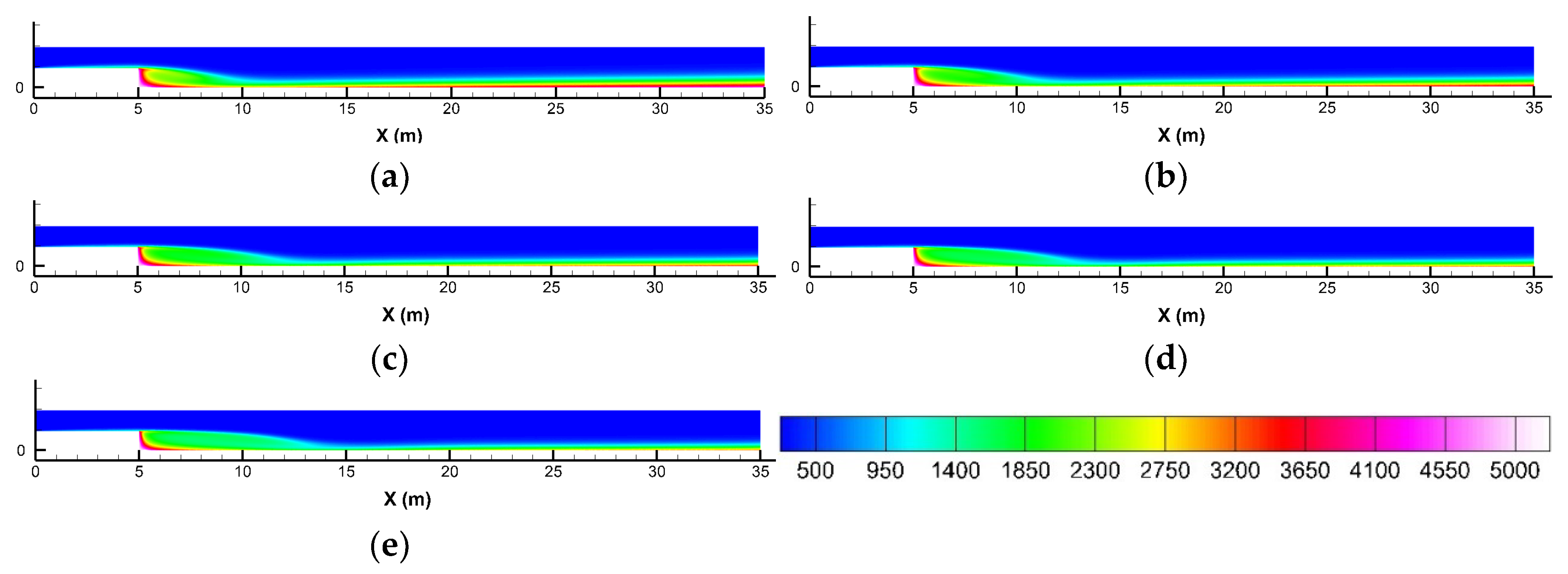
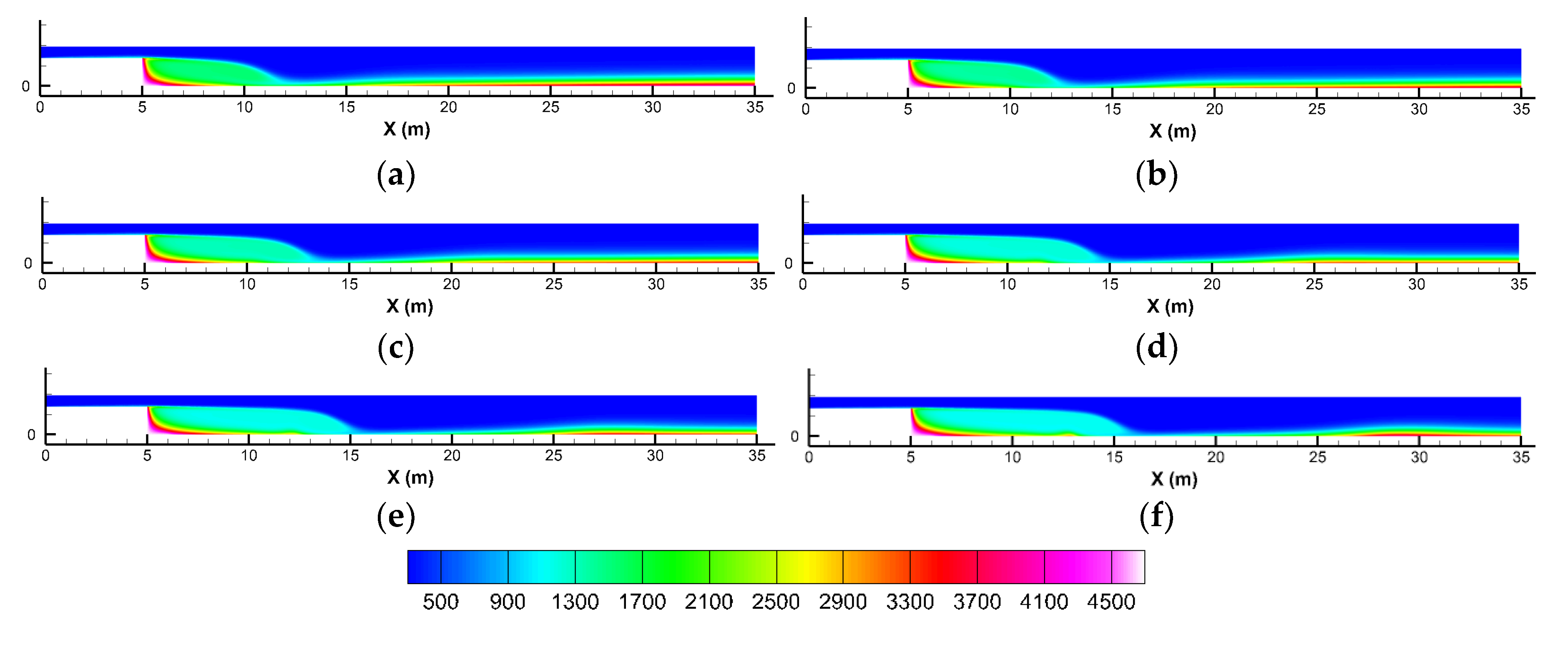
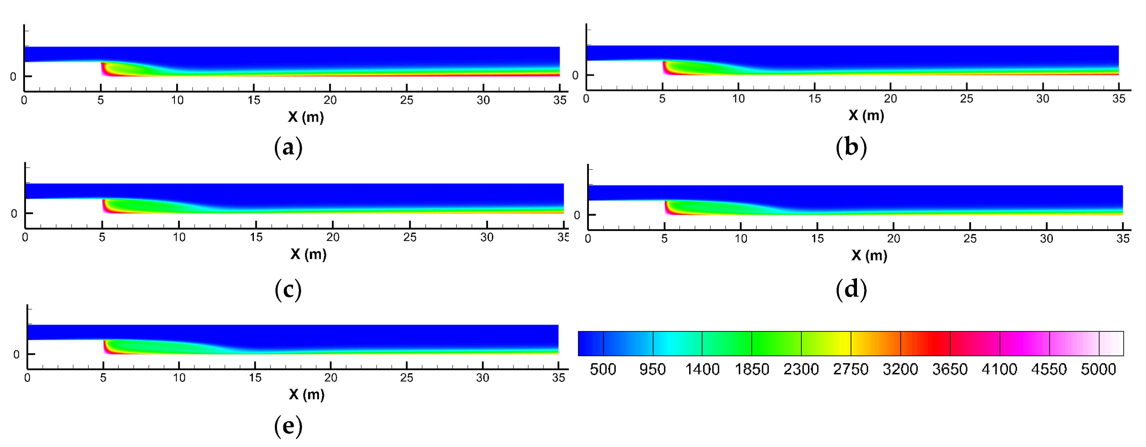
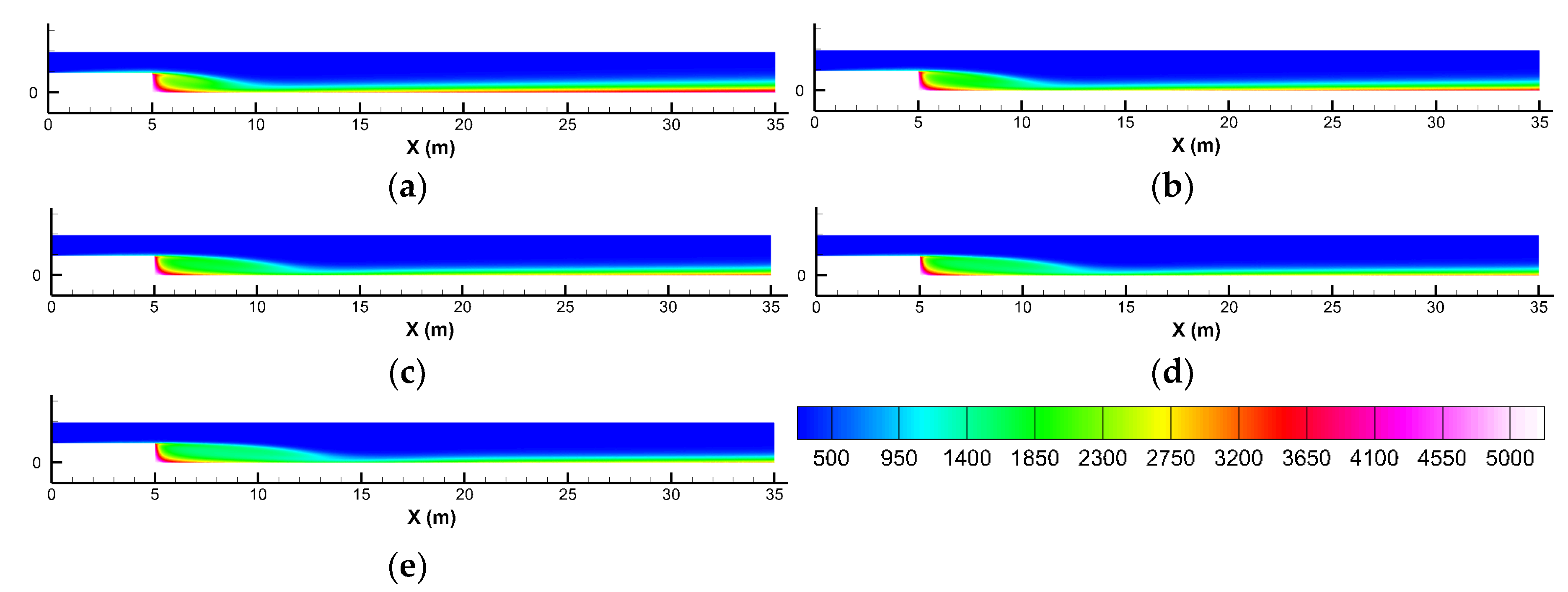
Figure 4.
Temperature contours at various Reynolds numbers; (a) 200, (b) 300, (c) 400, (d) 500, and (e) 600.
Figure 4.
Temperature contours at various Reynolds numbers; (a) 200, (b) 300, (c) 400, (d) 500, and (e) 600.
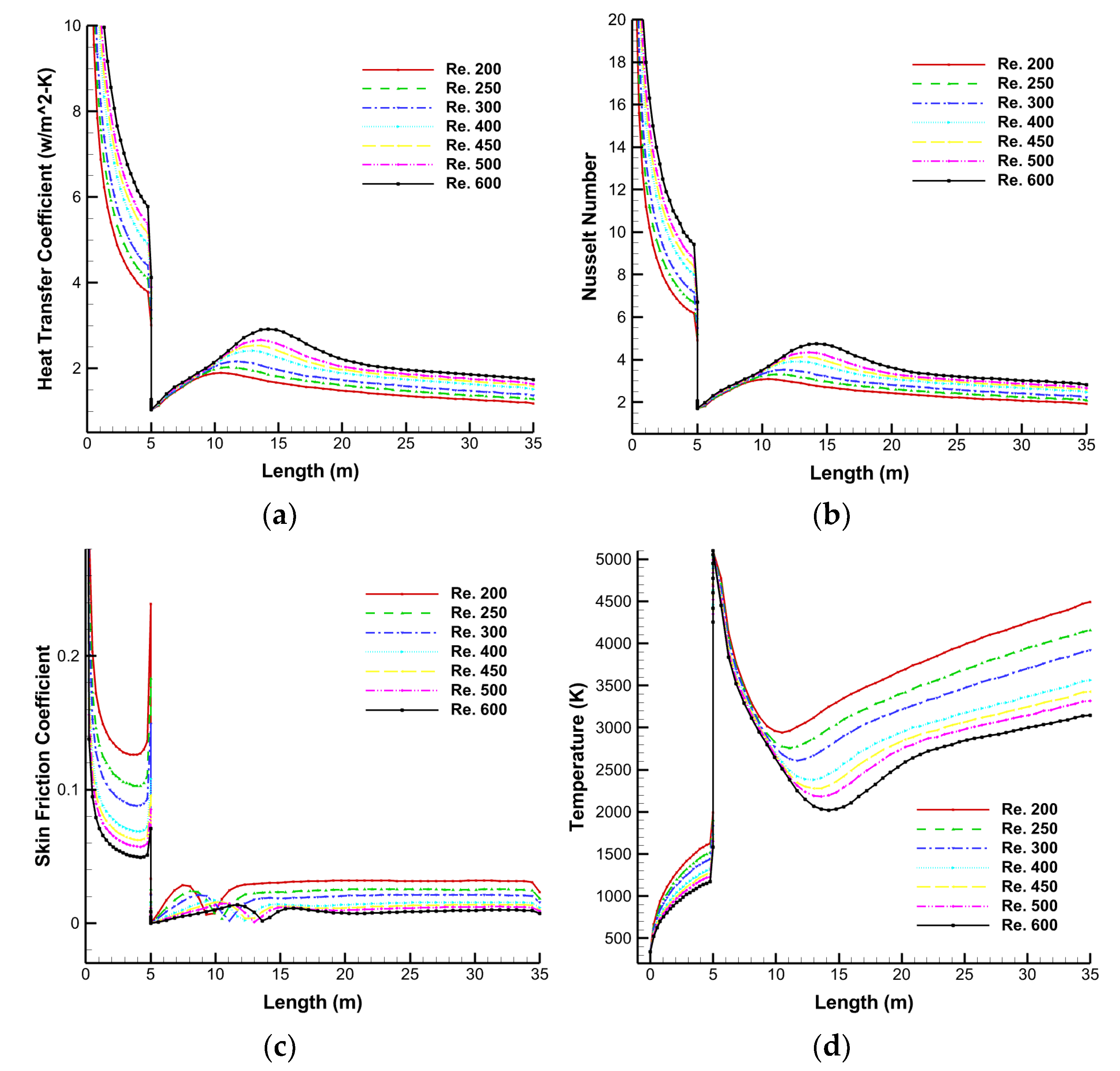
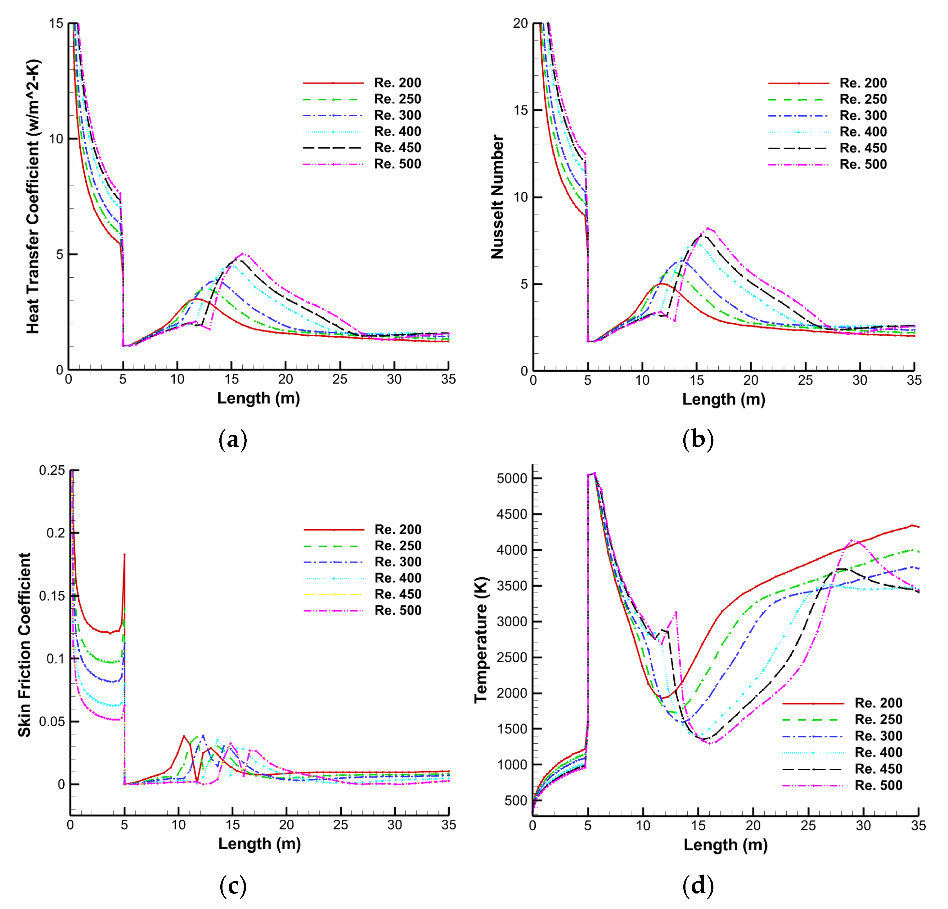
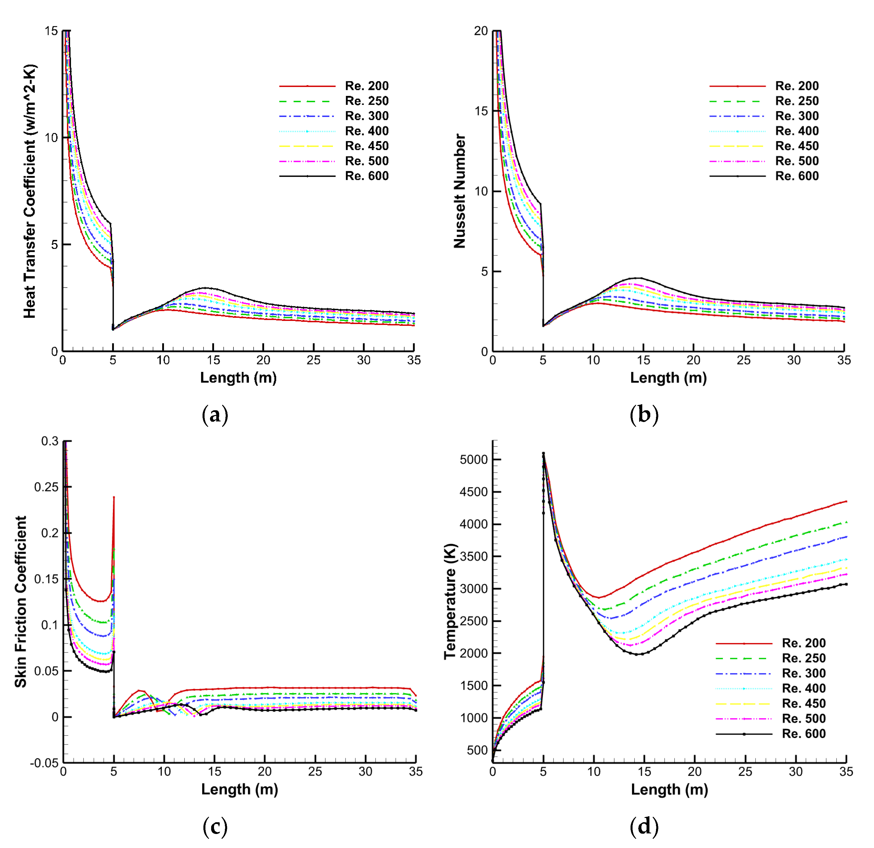
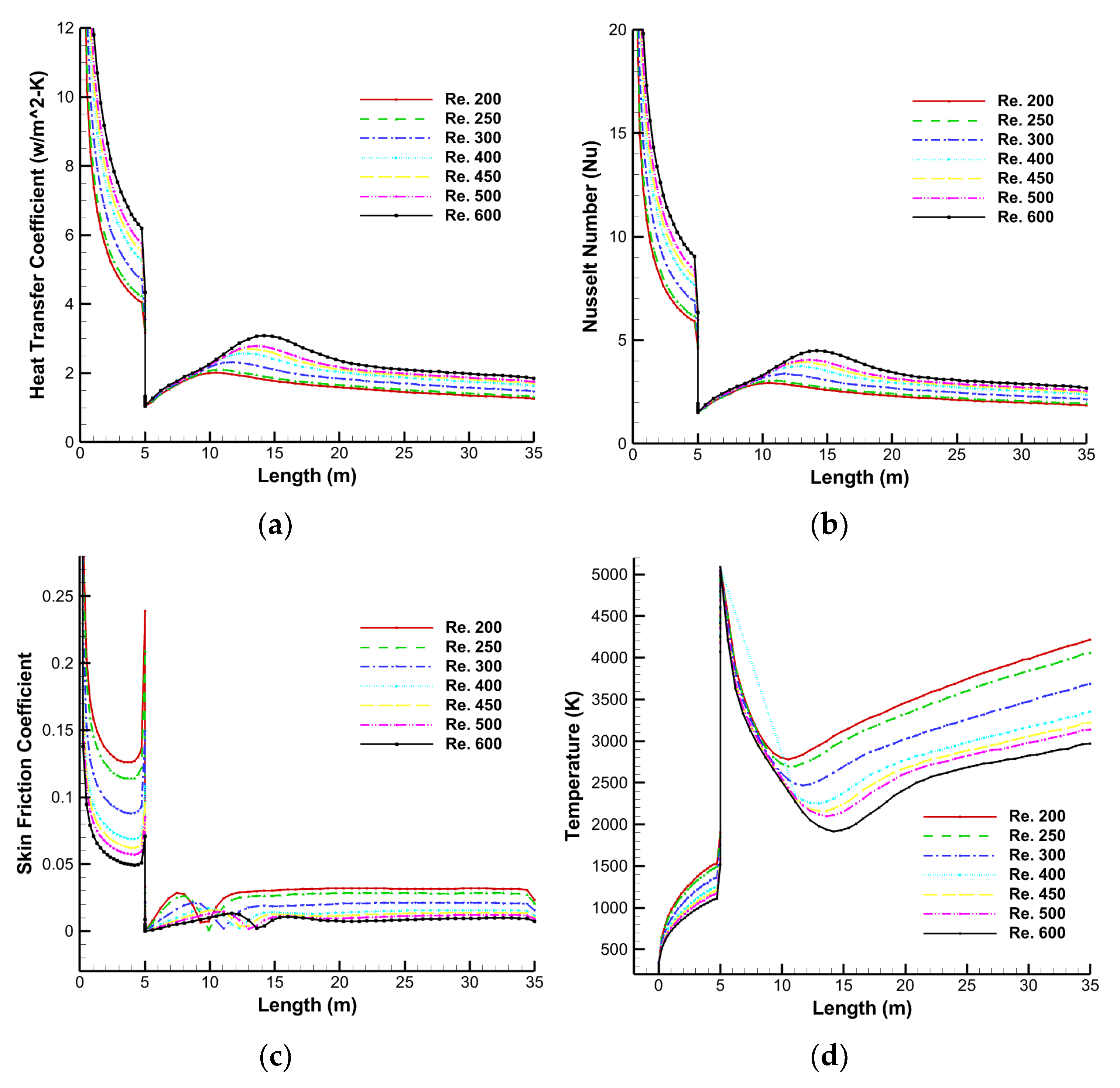
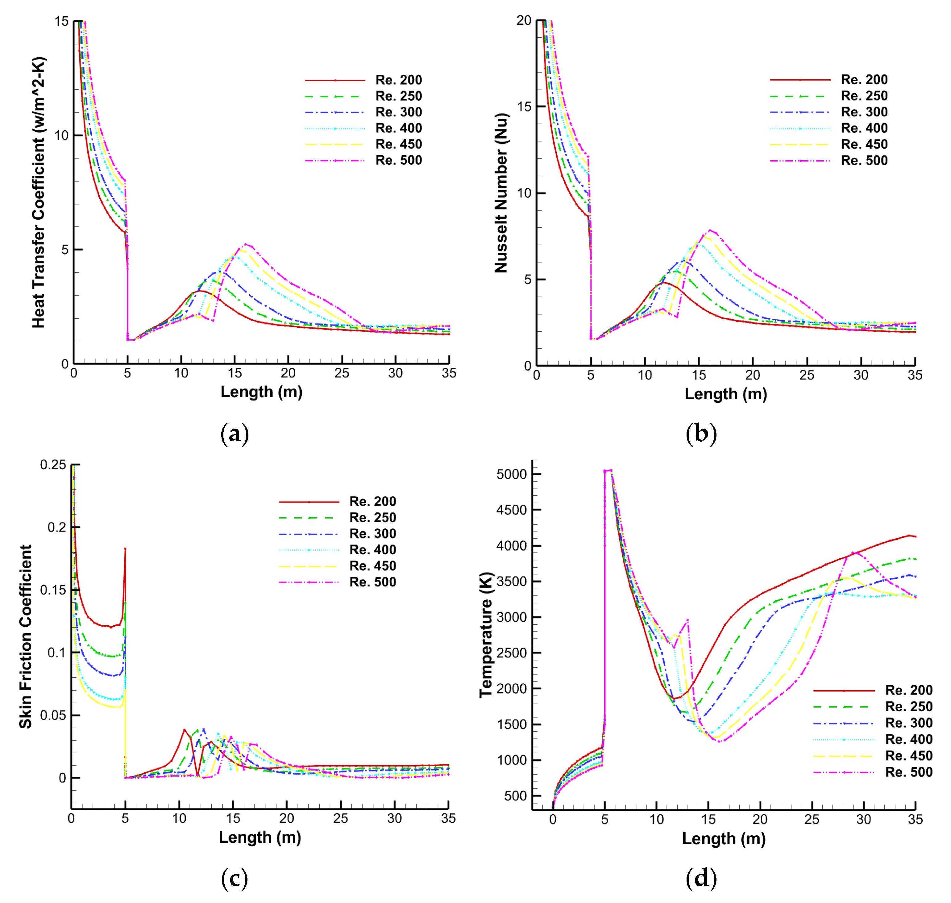
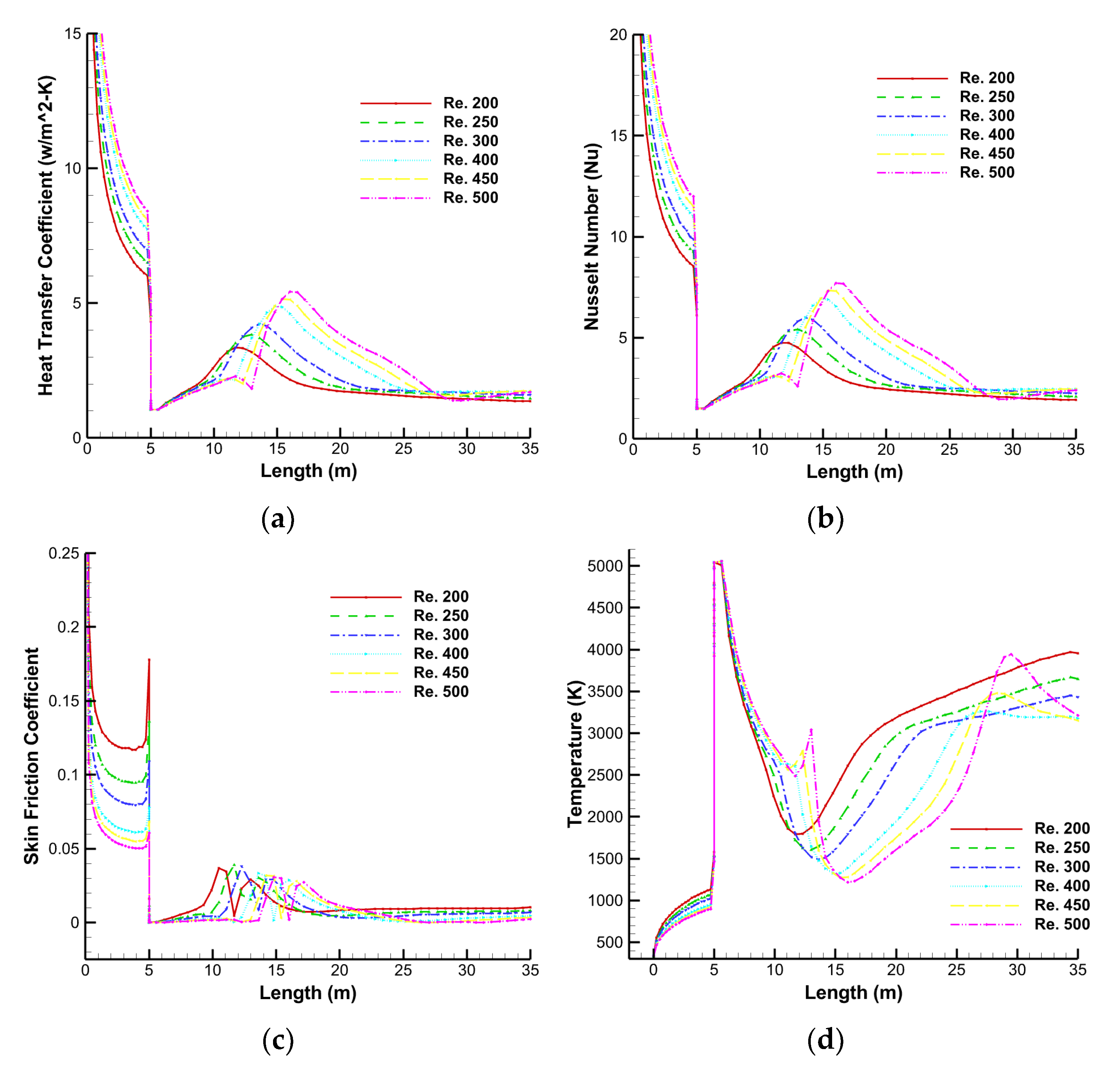
Figure 5.
Heat transfer parameters for varying Reynolds numbers: (a) heat transfer coefficient, (b) Nusselt number, (c) skin friction coefficient, and (d) temperature.
Figure 5.
Heat transfer parameters for varying Reynolds numbers: (a) heat transfer coefficient, (b) Nusselt number, (c) skin friction coefficient, and (d) temperature.
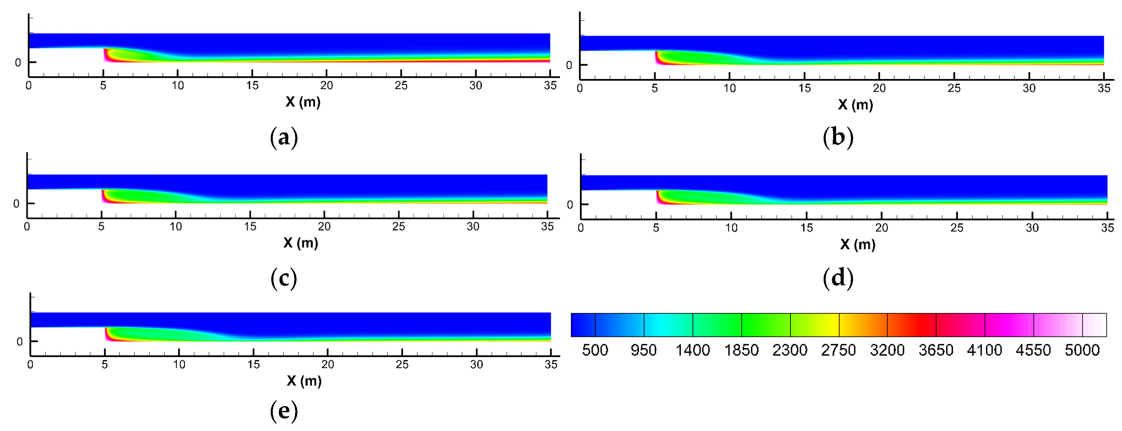
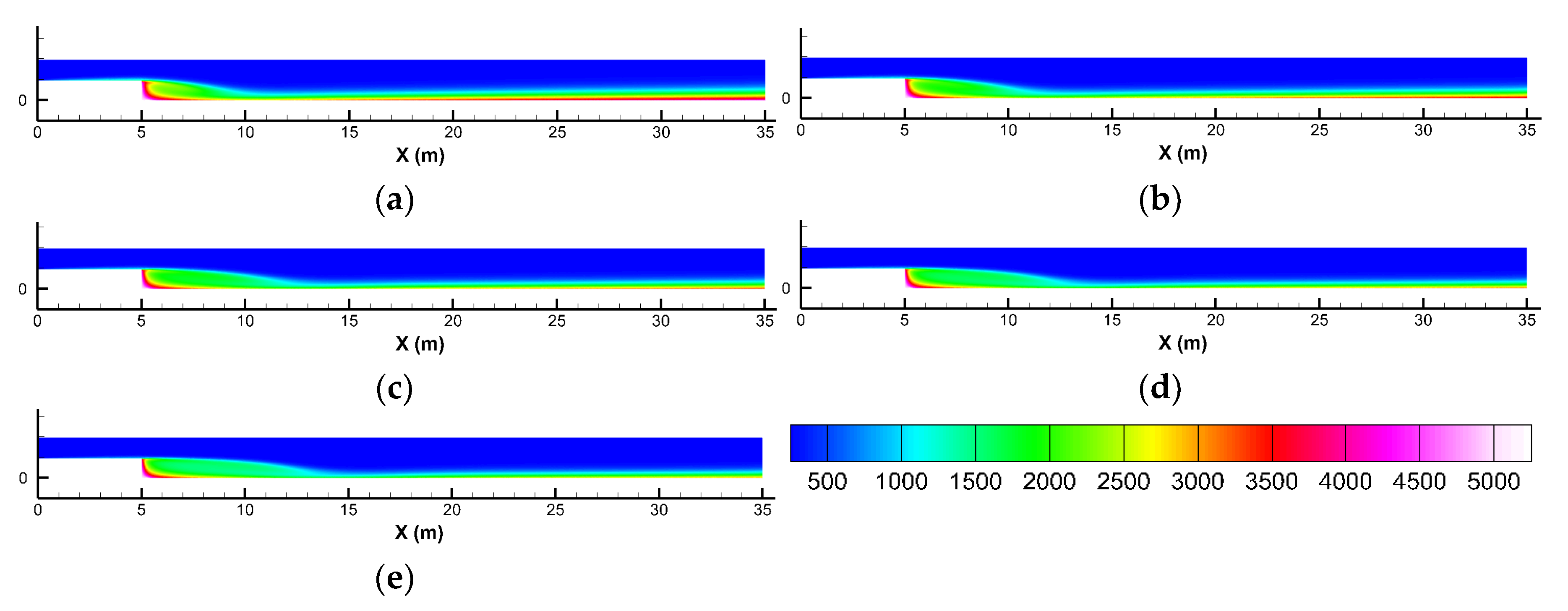
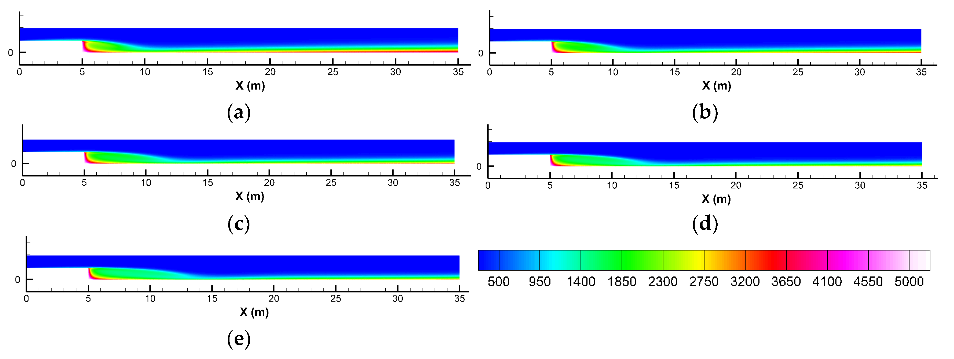
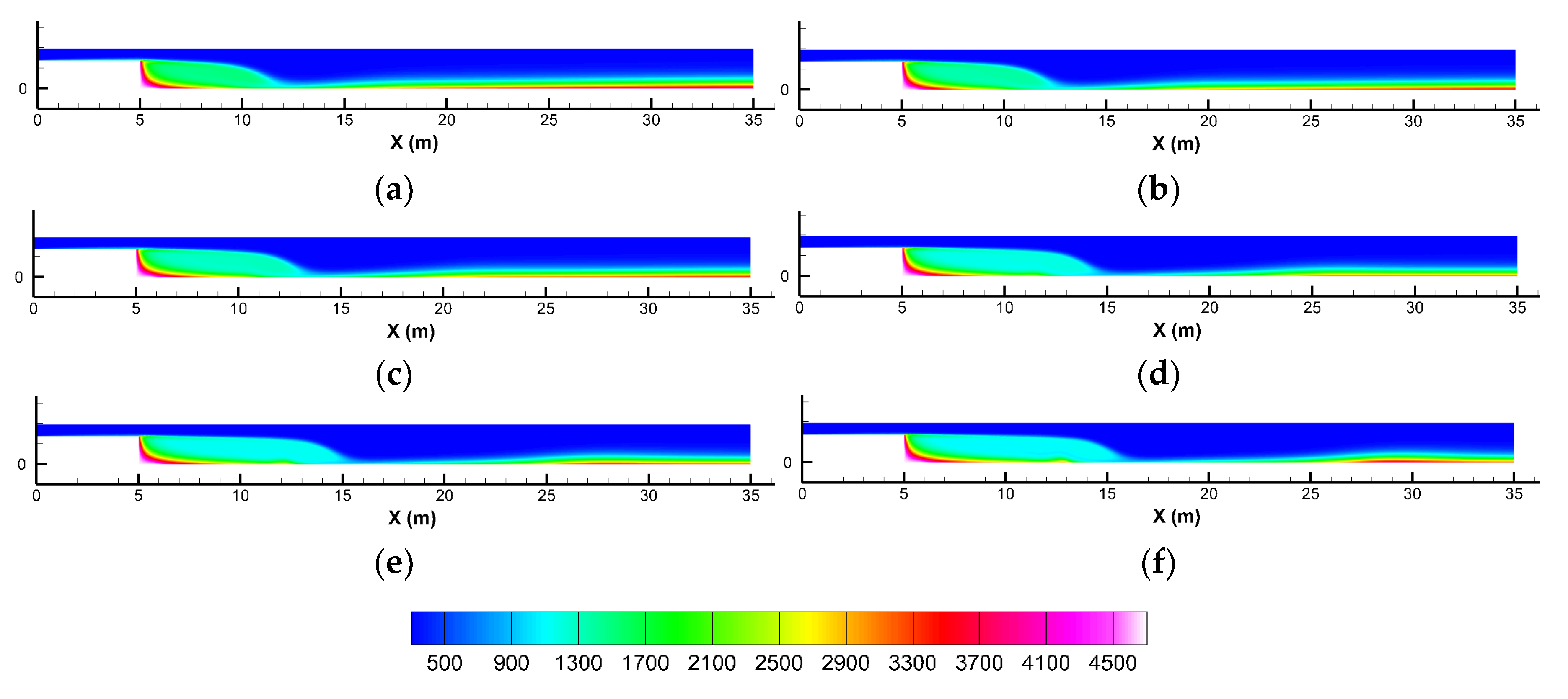
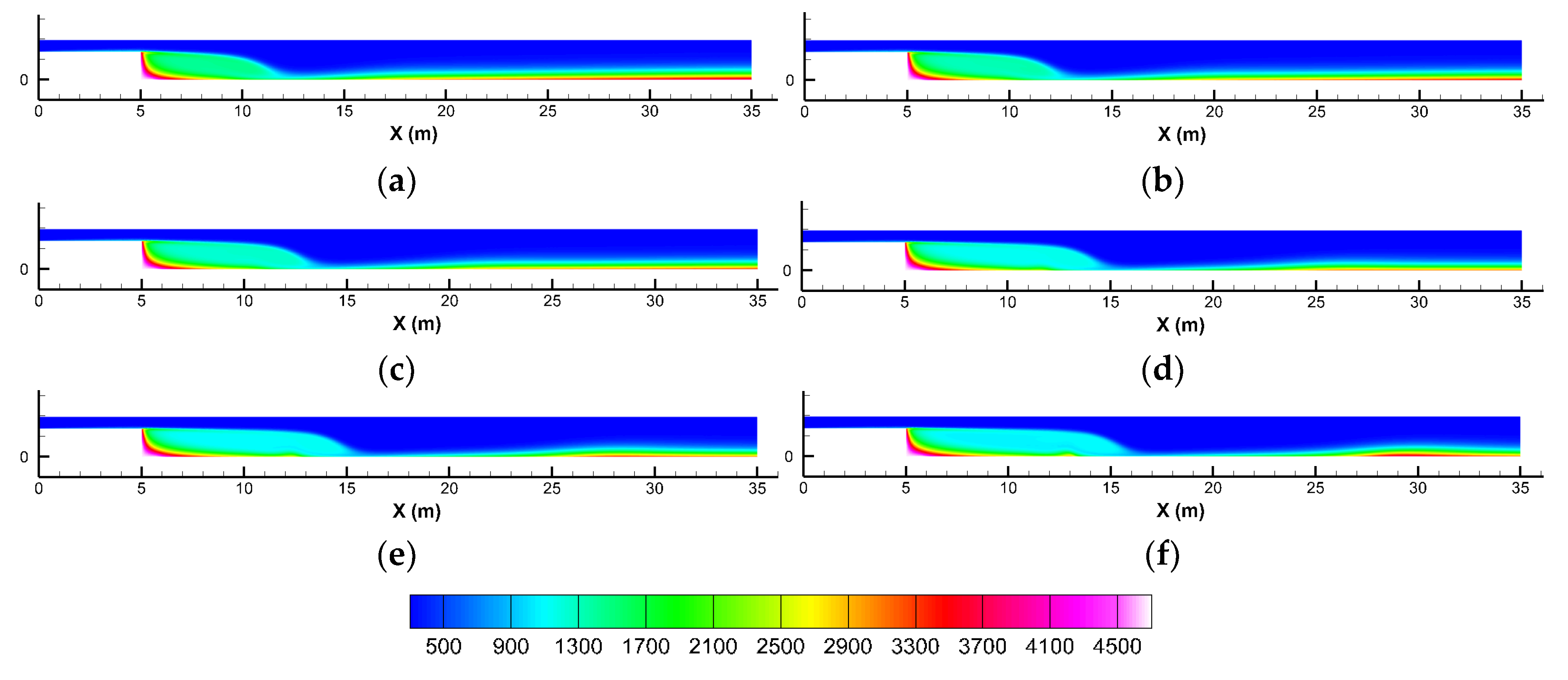
Figure 6.
Temperature contours at various Reynolds numbers; (a) 200, (b) 250, (c) 300, (d) 400, (e) 450, and (f) 500.
Figure 6.
Temperature contours at various Reynolds numbers; (a) 200, (b) 250, (c) 300, (d) 400, (e) 450, and (f) 500.
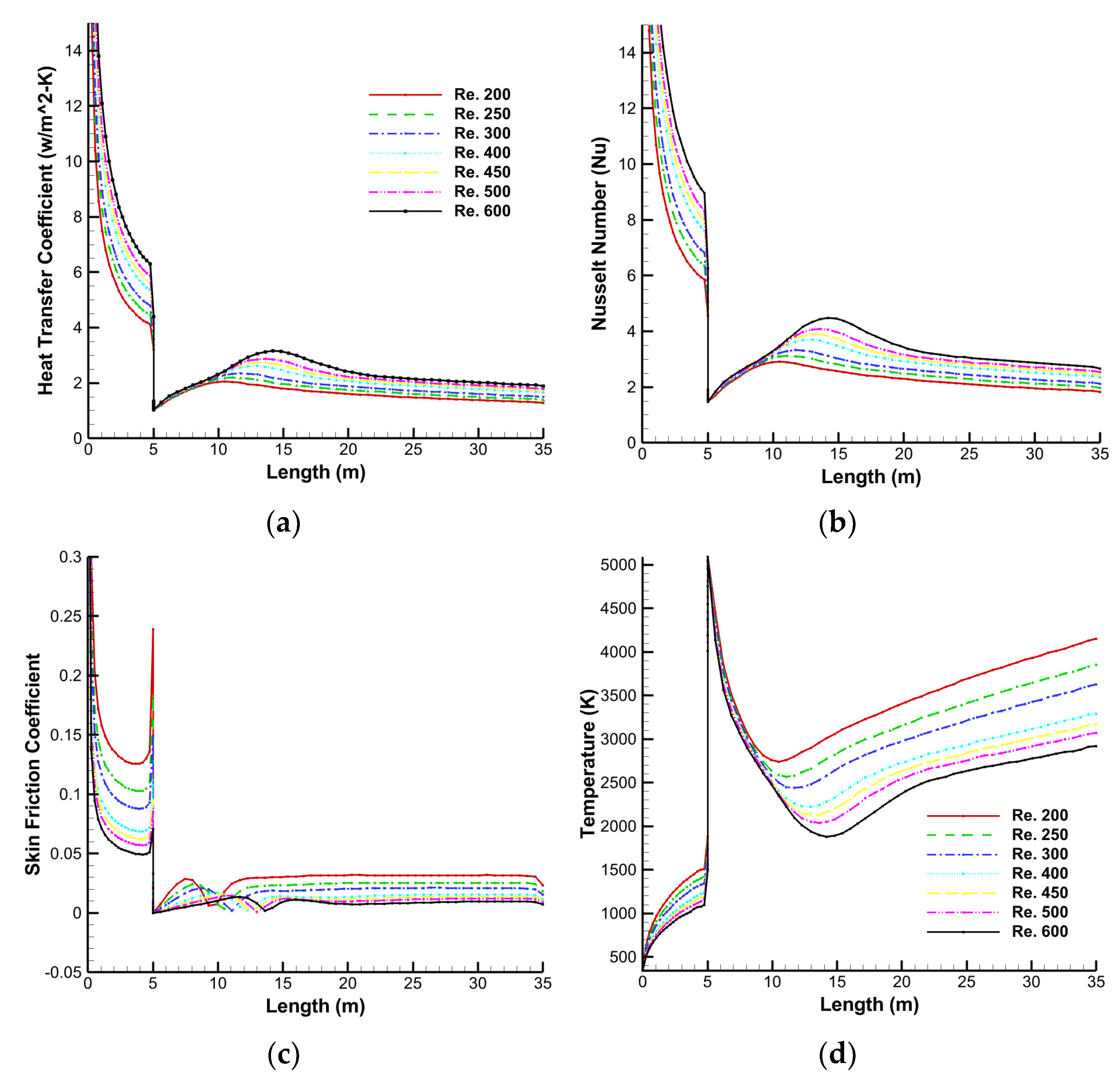
Figure 7.
Streamlines various Reynolds numbers; (a) 200, (b) 250, (c) 300, (d) 400, (e) 450, and (f) 500.
Figure 7.
Streamlines various Reynolds numbers; (a) 200, (b) 250, (c) 300, (d) 400, (e) 450, and (f) 500.
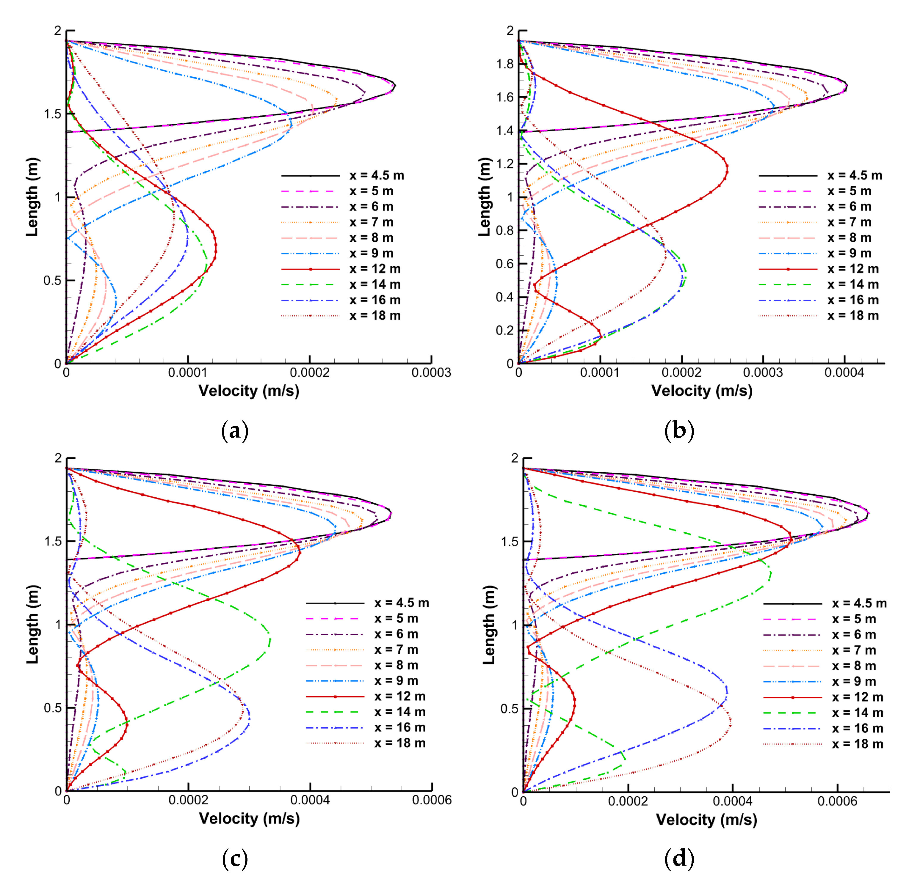
Figure 8.
Velocity profiles for Reynolds numbers at various lengths along the lateral directions from inlet boundary; (a) 200, (b) 300, (c) 400, and (d) 500.
Figure 8.
Velocity profiles for Reynolds numbers at various lengths along the lateral directions from inlet boundary; (a) 200, (b) 300, (c) 400, and (d) 500.
Figure 9.
Length of primary recirculation region behind the backward facing step having an expansion ratio of 3.5.
Figure 9.
Length of primary recirculation region behind the backward facing step having an expansion ratio of 3.5.
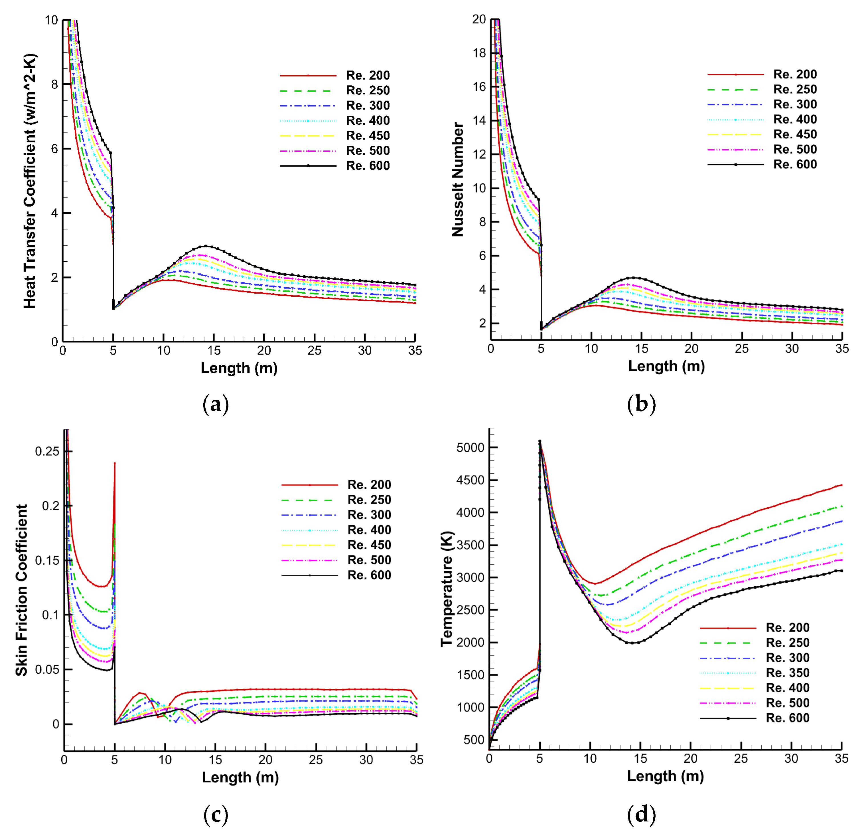
Figure 10.
(a) Heat transfer coefficient, (b) Nusselt number, (c) skin friction coefficient, and (d) temperature.
Figure 10.
(a) Heat transfer coefficient, (b) Nusselt number, (c) skin friction coefficient, and (d) temperature.
Figure 11.
Temperature contours at various Reynolds numbers at volume fraction 1%; (a) 200, (b) 300, (c) 400, (d) 500, and (e) 600.
Figure 11.
Temperature contours at various Reynolds numbers at volume fraction 1%; (a) 200, (b) 300, (c) 400, (d) 500, and (e) 600.
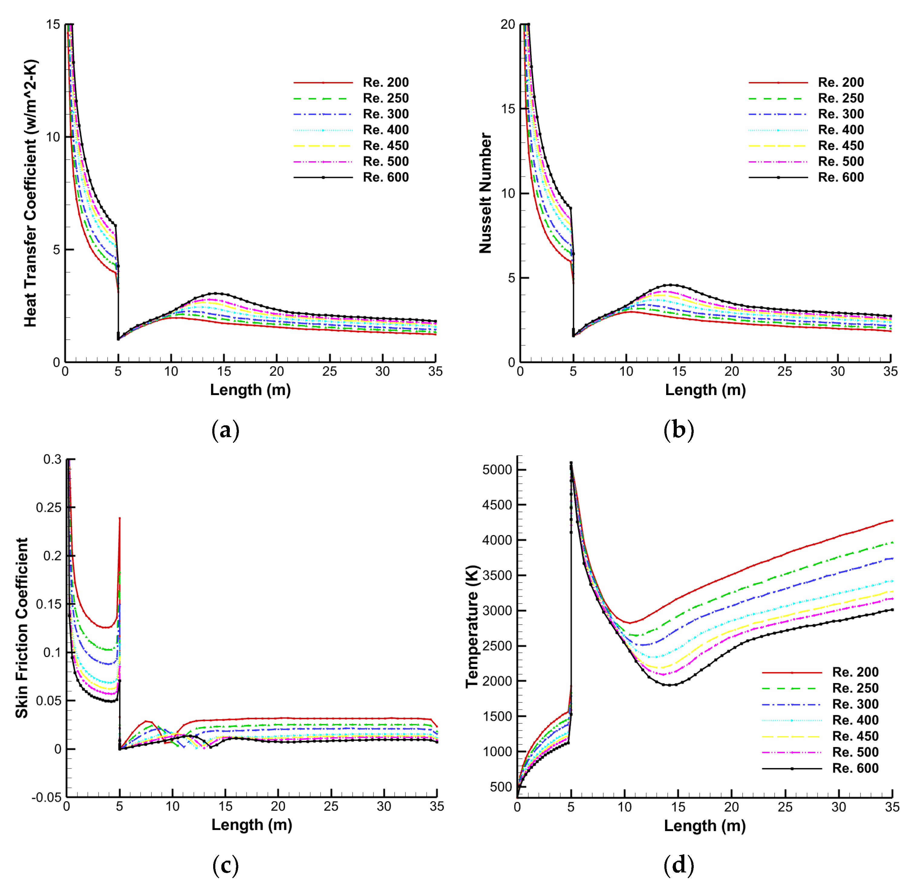
Figure 12.
Heat transfer parameters for varying Reynolds numbers for nanofluid at 1% volume fraction (a) heat transfer coefficient, (b) Nusselt number, (c) skin friction coefficient, and (d) temperature.
Figure 12.
Heat transfer parameters for varying Reynolds numbers for nanofluid at 1% volume fraction (a) heat transfer coefficient, (b) Nusselt number, (c) skin friction coefficient, and (d) temperature.
Figure 13.
Temperature contours at various Reynolds numbers at volume fraction 2%; (a) 200, (b) 300, (c) 400, (d) 500, and (e) 600.
Figure 13.
Temperature contours at various Reynolds numbers at volume fraction 2%; (a) 200, (b) 300, (c) 400, (d) 500, and (e) 600.
Figure 14.
Heat transfer parameters for varying Reynolds numbers for nanofluid at 2% volume fraction; (a) heat transfer coefficient, (b) Nusselt number, (c) skin friction coefficient, and (d) temperature.
Figure 14.
Heat transfer parameters for varying Reynolds numbers for nanofluid at 2% volume fraction; (a) heat transfer coefficient, (b) Nusselt number, (c) skin friction coefficient, and (d) temperature.
Figure 15.
Temperature contours at various Reynolds numbers at volume fraction 3%; (a) 200, (b) 300, (c) 400, (d) 500, and (e) 600.
Figure 15.
Temperature contours at various Reynolds numbers at volume fraction 3%; (a) 200, (b) 300, (c) 400, (d) 500, and (e) 600.
Figure 16.
Heat transfer parameters for varying Reynolds numbers for nanofluid at 3% volume fraction; (a) Heat transfer coefficient, (b) Nusselt number, (c) skin friction coefficient, and (d) temperature.
Figure 16.
Heat transfer parameters for varying Reynolds numbers for nanofluid at 3% volume fraction; (a) Heat transfer coefficient, (b) Nusselt number, (c) skin friction coefficient, and (d) temperature.
Figure 17.
Temperature contours at various Reynolds number at volume fraction 4%; (a) 200, (b) 300, (c) 400, (d) 500, and (e) 600.
Figure 17.
Temperature contours at various Reynolds number at volume fraction 4%; (a) 200, (b) 300, (c) 400, (d) 500, and (e) 600.
Figure 18.
Heat transfer parameters for varying Reynolds number for nanofluid at 4% volume fraction; (a) Heat transfer coefficient, (b) Nusselt number, (c) skin friction coefficient, and (d) temperature.
Figure 18.
Heat transfer parameters for varying Reynolds number for nanofluid at 4% volume fraction; (a) Heat transfer coefficient, (b) Nusselt number, (c) skin friction coefficient, and (d) temperature.
Figure 19.
Temperature contours at various Reynolds numbers at volume fraction 5%; (a) 200, (b) 300, (c) 400, (d) 500, and (e) 600.
Figure 19.
Temperature contours at various Reynolds numbers at volume fraction 5%; (a) 200, (b) 300, (c) 400, (d) 500, and (e) 600.
Figure 20.
Heat transfer parameters for varying Reynolds numbers for nanofluid at 5% volume fraction; (a) heat transfer coefficient, (b) Nusselt number, (c) skin friction coefficient, and (d) temperature.
Figure 20.
Heat transfer parameters for varying Reynolds numbers for nanofluid at 5% volume fraction; (a) heat transfer coefficient, (b) Nusselt number, (c) skin friction coefficient, and (d) temperature.
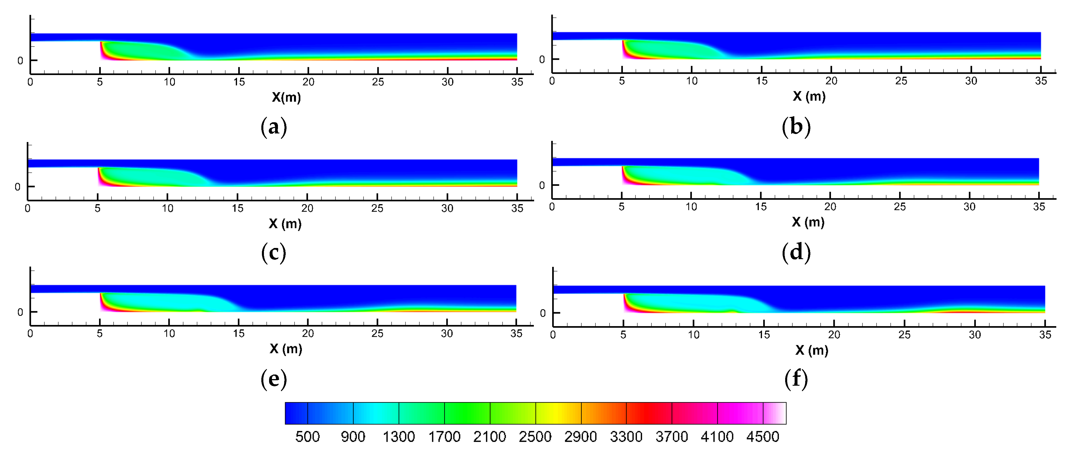
Figure 21.
Temperature contours at various Reynolds numbers; (a) 200, (b) 250, (c) 300, (d) 400, (e) 450, and (f) 500.
Figure 21.
Temperature contours at various Reynolds numbers; (a) 200, (b) 250, (c) 300, (d) 400, (e) 450, and (f) 500.
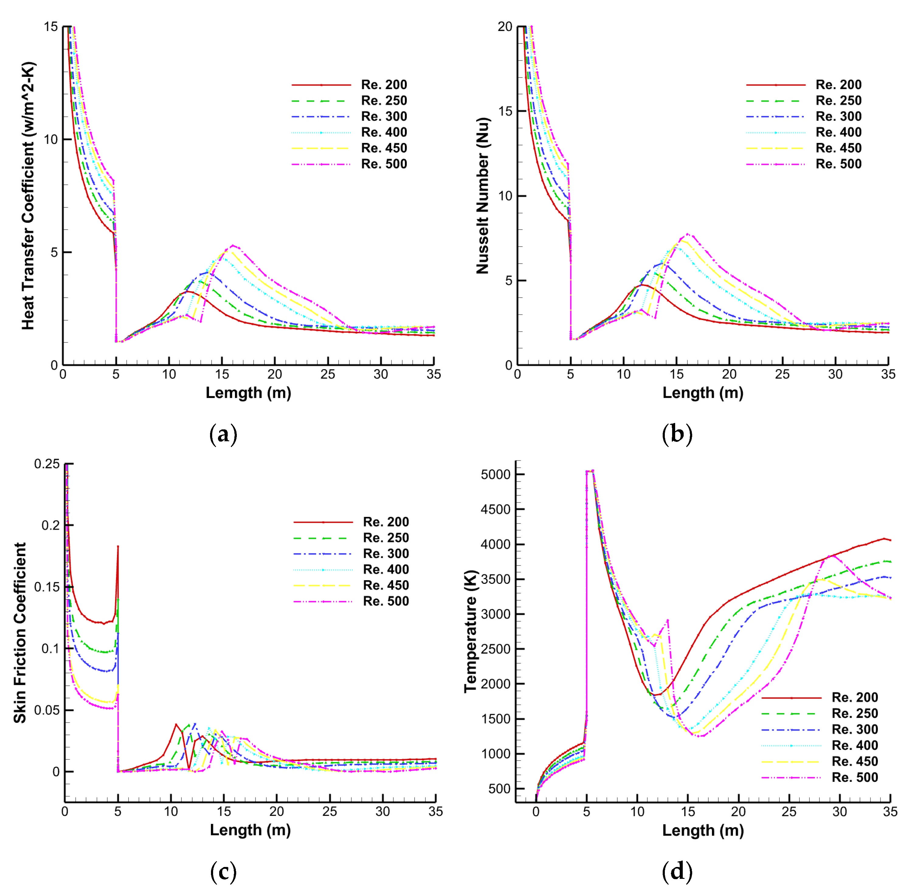
Figure 22.
Heat transfer parameters for varying Reynolds numbers for nanofluid at 1% volume fraction; (a) heat transfer coefficient, (b) Nusselt number, (c) skin friction coefficient, and (d) temperature.
Figure 22.
Heat transfer parameters for varying Reynolds numbers for nanofluid at 1% volume fraction; (a) heat transfer coefficient, (b) Nusselt number, (c) skin friction coefficient, and (d) temperature.
Figure 23.
Temperature contours at various Reynolds numbers; (a) 200, (b) 250, (c) 300, (d) 400, (e) 450, and (f) 500.
Figure 23.
Temperature contours at various Reynolds numbers; (a) 200, (b) 250, (c) 300, (d) 400, (e) 450, and (f) 500.
Figure 24.
Heat transfer parameters for varying Reynolds numbers for nanofluid at 2% volume fraction; (a) heat transfer coefficient, (b) Nusselt number, (c) skin friction coefficient, and (d) temperature.
Figure 24.
Heat transfer parameters for varying Reynolds numbers for nanofluid at 2% volume fraction; (a) heat transfer coefficient, (b) Nusselt number, (c) skin friction coefficient, and (d) temperature.
Figure 25.
Temperature contours at various Reynolds numbers; (a) 200, (b) 250, (c) 300, (d) 400, (e) 450, and (f) 500.
Figure 25.
Temperature contours at various Reynolds numbers; (a) 200, (b) 250, (c) 300, (d) 400, (e) 450, and (f) 500.
Figure 26.
Heat transfer parameters for varying Reynolds numbers for nanofluid at 3% volume fraction; (a) heat transfer coefficient, (b) Nusselt number, (c) skin friction coefficient, and (d) temperature.
Figure 26.
Heat transfer parameters for varying Reynolds numbers for nanofluid at 3% volume fraction; (a) heat transfer coefficient, (b) Nusselt number, (c) skin friction coefficient, and (d) temperature.
Figure 27.
Temperature contours at various Reynolds numbers; (a) 200, (b) 250, (c) 300, (d) 400, (e) 450, and (f) 500.
Figure 27.
Temperature contours at various Reynolds numbers; (a) 200, (b) 250, (c) 300, (d) 400, (e) 450, and (f) 500.
Figure 28.
Heat transfer parameters for varying Reynolds numbers for nanofluid at 4% volume fraction; (a) heat transfer coefficient, (b) Nusselt number, (c) skin friction coefficient, and (d) temperature.
Figure 28.
Heat transfer parameters for varying Reynolds numbers for nanofluid at 4% volume fraction; (a) heat transfer coefficient, (b) Nusselt number, (c) skin friction coefficient, and (d) temperature.
Figure 29.
Temperature contours at various Reynolds numbers; (a) 200, (b) 250, (c) 300, (d) 400, (e) 450, and (f) 500.
Figure 29.
Temperature contours at various Reynolds numbers; (a) 200, (b) 250, (c) 300, (d) 400, (e) 450, and (f) 500.
Figure 30.
Heat transfer parameters for varying Reynolds numbers for nanofluid at 5% volume fraction; (a) heat transfer coefficient, (b) Nusselt number, (c) skin friction coefficient, and (d) temperature.
Figure 30.
Heat transfer parameters for varying Reynolds numbers for nanofluid at 5% volume fraction; (a) heat transfer coefficient, (b) Nusselt number, (c) skin friction coefficient, and (d) temperature.
Table 1.
Material properties.
Table 1.
Material properties.
| Materials | Density | Thermal Conductivity | Specific Heat | Viscosity |
|---|
| Al2O3 [70,71] | 3600 | 36 | 765 | - |
| H2O [71] | 997.1 | 0.613 | 4179.1 | 0.001 |
Table 2.
Grid independence study at Reynolds number 100.
Table 2.
Grid independence study at Reynolds number 100.
| Mesh | No. of Elements | Length of Recirculation Zone | Biswas et al. [7] |
|---|
| 1 | 101,656 | 2.735 | 2.64 |
| 2 | 248,805 | 2.63 |
| 3 | 473,202 | 2.65 |
Table 3.
Selected mesh details.
Table 3.
Selected mesh details.
| Mesh | No. of Elements | Max. Skewness | Avg. Skewness |
|---|
| 1 | 248,805 | 0.60092 | 0.024169 |
| 2 | 231,225 | 0.78036 | 0.027475 |
Table 4.
Average coefficient of heat transfer (w/m2-K) at bottom wall for various Reynolds numbers and volume fractions.
Table 4.
Average coefficient of heat transfer (w/m2-K) at bottom wall for various Reynolds numbers and volume fractions.
| Re. | = 0%
| = 1%
| = 2%
| = 3%
| = 4%
| = 5%
|
|---|
| 200 | 2.676 | 2.721 | 2.767 | 2.814 | 2.862 | 2.912 |
| 250 | 2.901 | 2.948 | 2.999 | 3.051 | 2.981 | 3.157 |
| 300 | 3.097 | 3.149 | 3.204 | 3.258 | 3.315 | 3.373 |
| 400 | 3.439 | 3.497 | 3.557 | 3.599 | 3.682 | 3.746 |
| 450 | 3.509 | 3.653 | 3.717 | 3.787 | 3.847 | 3.914 |
| 500 | 3.731 | 3.801 | 3.866 | 3.933 | 3.987 | 4.072 |
Table 5.
Average outlet temperature for various Reynolds numbers and volume fractions.
Table 5.
Average outlet temperature for various Reynolds numbers and volume fractions.
| Re. | = 0%
| = 1%
| = 2%
| = 3%
| = 4%
| = 5%
|
|---|
| 200 | 985.514 | 982.999 | 979.681 | 996.206 | 972.392 | 968.231 |
| 250 | 881.554 | 879.257 | 876.299 | 873.201 | 921.285 | 866.314 |
| 300 | 812.561 | 810.471 | 807.765 | 804.961 | 801.896 | 798.587 |
| 400 | 715.037 | 713.241 | 710.973 | 713.695 | 706.055 | 703.291 |
| 450 | 682.092 | 680.392 | 678.264 | 676.063 | 673.687 | 671.161 |
| 500 | 656.011 | 654.441 | 652.438 | 650.346 | 651.441 | 645.679 |
Table 6.
Average coefficient of heat transfer (w/m2-K) at bottom wall for various Reynolds numbers and volume fractions.
Table 6.
Average coefficient of heat transfer (w/m2-K) at bottom wall for various Reynolds numbers and volume fractions.
| Re. | = 0%
| = 1%
| = 2%
| = 3%
| = 4%
| = 5%
|
|---|
| 200 | 2.822 | 2.868 | 2.915 | 2.964 | 3.014 | 3.096 |
| 250 | 3.071 | 3.121 | 3.172 | 3.225 | 3.279 | 3.369 |
| 300 | 3.288 | 3.341 | 3.397 | 3.454 | 3.512 | 3.607 |
| 400 | 3.651 | 3.711 | 3.751 | 3.836 | 3.901 | 4.006 |
| 450 | 3.801 | 3.863 | 3.928 | 3.994 | 4.062 | 4.171 |
| 500 | 3.938 | 4.003 | 4.071 | 4.139 | 4.211 | 4.319 |
Table 7.
Average outlet temperature for various Reynolds numbers and volume fractions.
Table 7.
Average outlet temperature for various Reynolds numbers and volume fractions.
| Re. | = 0%
| = 1%
| = 2%
| = 3%
| = 4%
| = 5%
|
|---|
| 200 | 982.637 | 980.281 | 977.138 | 973.812 | 970.170 | 952.937 |
| 250 | 875.913 | 873.799 | 871.005 | 868.101 | 864.911 | 850.448 |
| 300 | 803.036 | 801.078 | 798.547 | 795.912 | 793.051 | 780.773 |
| 400 | 722.028 | 720.151 | 747.907 | 715.423 | 712.793 | 705.128 |
| 450 | 709.257 | 707.209 | 704.747 | 702.305 | 699.578 | 694.095 |
| 500 | 715.197 | 712.908 | 710.112 | 707.211 | 704.291 | 710.633 |


