Article

Design and Analysis of a Compression and Separation Device for Multi-Satellite Deployment

1
School of Mechatronics Engineering, Harbin Institute of Technology, Harbin 150080, China
2
Shanghai Institute of Satellite Engineering, Shanghai 201109, China
*
Author to whom correspondence should be addressed.
Aerospace 2022, 9(8), 446; https://doi.org/10.3390/aerospace9080446
Submission received: 19 July 2022 / Revised: 4 August 2022 / Accepted: 11 August 2022 / Published: 14 August 2022
(This article belongs to the Special Issue Emerging Space Missions and Technologies)

Abstract

:
The launch method of one arrow with multiple satellites can greatly shorten the time for constellation networking and improve the deployment efficiency. A new compression and separation device with a four-bar perimeter arrangement is proposed for multi-satellite compaction and in-orbit release. A compression device with gap elimination is designed to implement the reliable compaction of stacked flat satellites. An electromagnetic separation device is proposed to achieve the fast, low-interference release of multi-satellites. The dynamic model with flexible guide bars is established. The separation characteristics of multiple satellites are analyzed by the kinematic simulation. The prototype is developed, and the related experiment is implemented. The results show that the four-guide-bar-edge arrangement scheme with a gap elimination device achieves reliable locking and fast separation under a vibration environment. The dynamic separation characteristics of satellites are investigated by the air floatation experiments. The results show that a stable separation speed and low disturbance angular velocity are achieved under 10% spring error.

1. Introduction

Multiple satellites working in concert can implement space tasks that cannot be accomplished by a single robust satellite, such as remote sensing, constellations, and formation [1,2,3]. The satellites are generally launched and released in a single rocket, which can greatly shorten the time of constellation networking and improve the launch efficiency. The compression and separation devices for multi-satellite launch deployment scenarios are mainly divided into three categories: box-storage type [4,5,6], wall-mounted type [7], and stacked compression type [8,9]. The box-storage type is applied to the storage and release of multiple nano-satellites and pico-satellites of the same or similar size. The wall-mounted type is suitable to the launch scenario of multiple rectangular satellites or satellites with trapezoidal cross-section. The stacked compression type is applied to compress and release the multiple flat-shaped satellites, such as Starlink and Smart Dusts [10]. In the paper, the stacked compression method is adopted to lock and release multiple flat satellites.
In a multi-satellite launch, the design of the locking connection and separation system for multiple satellites is the key technology to be solved first. The layout and installation of multiple satellites in the rocket, the anti-collision problem of separation, and the connection method to minimize the impact between satellites and ensure effective separation into orbit are issues that need to be considered when designing the locking connection and separation system. In the compression connection and separation system, traditional locking release devices and initiating explosive devices [11] are used on spacecraft, such as pin pullers, explosive bolts, initiating explosive nuts, and cutters. The unlocking impact of initiating explosive devices is large, reaching 3000~20,000 g. It also has the disadvantages of hard storage and transportation, safety risks, and can only be used once so they cannot be tested and verified. In recent years, miniaturization and precision of satellites and accessories have put forward higher requirements for locking and releasing devices. The application of the new non-initiating explosive separation device in the scene of one rocket with multiple satellites has not been seen yet.
The driving principles of non-pyrotechnic unlocking devices mainly include: piezoelectric ceramic drive [12], electromagnetic force drive [13], shape memory alloy drive [14,15], and fusing or thermal cutting [16,17]. Compared with other drive sources, SMA wire-driven based unlockers have the advantages of fast response speed, high carrying capacity, low impact and reusability. The unlocker of load-bearing structures mainly includes the steel ball load-bearing and thread load-bearing. The thread load-bearing is divided into split-nut load-bearing and non-self-locking nut load-bearing. The steel ball load-bearing requires small driving forces to overcome the rolling friction because the contact form between the steel ball and other structures is point and line contact. But its bearing capacity is relatively weak. The split-nut type has stronger capacity, the thread is a self-locking thread, and the preload can be used to realize rapid separation when unlocking. But it is easy to cause uneven load distribution. The carrying capacity of the non-self-locking nut type is stronger than that of the split-nut type under the same size, but it needs more complicated load decay mechanism to reduce the trigger force.
Guide bars are used to run through the flat satellites to achieve inter-satellite compression and guidance. The arrangement of the guide bars and the compression device affect the load-bearing capacity of the compression device and the dynamic characteristics of the satellites. Due to the long size of the guide bar and cantilever characteristics, multiple contact collisions occur between the guide bars and the satellites, interfering with the separation speed and angular velocity. The main innovation and contribution of this paper are as follows: For reliable compression and fast release of multiple flat satellites, a configuration with four guide bars arranged at corners is proposed. A new compression and release device is designed and a dynamic model containing a flexible body is established. It is experimentally verified that the proposed device achieves reliable compression and fast separation and release. The stable separation velocity and low interference angular velocity are achieved. In Section 2, a new compression mechanism and separation-release mechanism are demonstrated to achieve reliable compression during satellite lift-off and fast low-interference separation in orbit. Section 3 investigates the mutual collision between the satellites and the internal guide bars. The guide bar is regarded as a flexible body because of the long size and cantilever characteristics. The dynamic model of the contact collision between the satellite and the guide bars is established. Section 4 analyzes the separation characteristics of the multiple satellites. Section 5 develops a scaling prototype, and experimentally investigates the load-bearing capacity and the separation characteristics. Different from the traditional way of rope suspension of the counterpart, an air-floating platform is used to compensate the satellite gravity. The stable separation velocity and the lower angular velocity of the satellites are verified.

2. Structure and Working Principle

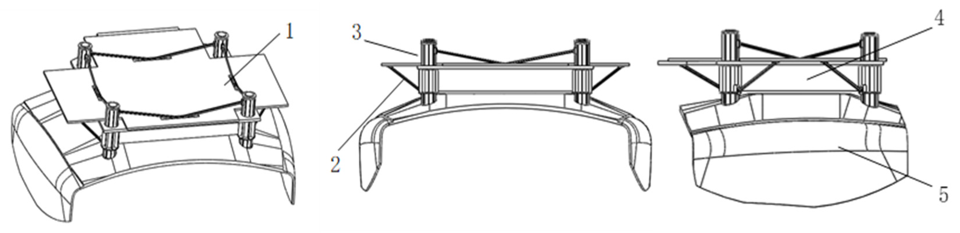
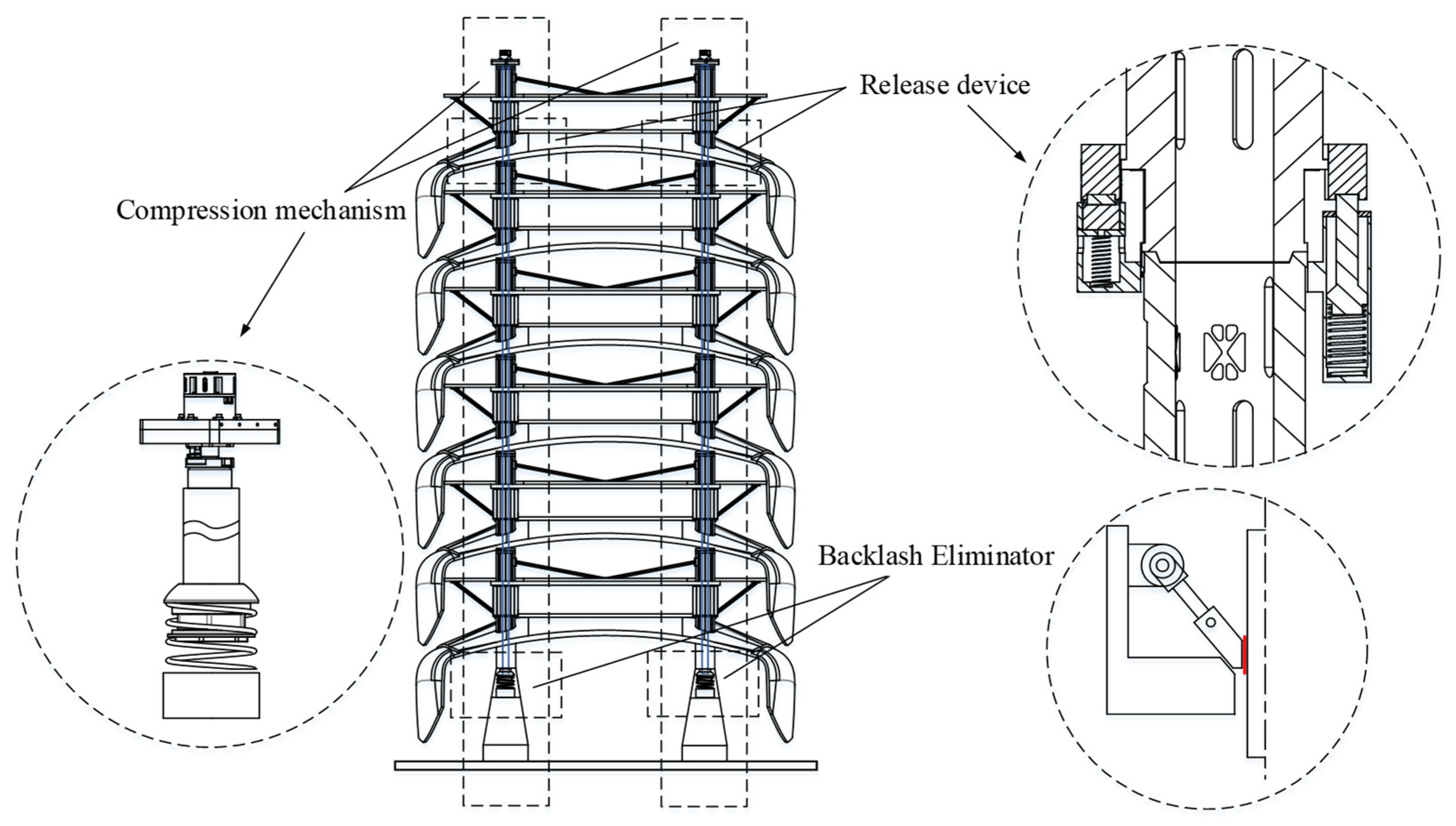
2.1. System Composition

The structure of a flat panel satellite is shown in Figure 1. The configuration of this flat satellite can make full use of the envelope space for delivery and achieve large-scale launch network. The four corners of the satellite have hollow bearing pillars for multiple satellites stacked along the axial direction and bearing forces. For the locking and ejection separation of satellites in the lift-off phase and the orbit phase, the compression device and ejection separation devices are designed respectively, as shown in Figure 2. The satellites are stacked on the carrier platform through the guide bars in the longitudinal direction. The satellite group is pre-tightened by the centralized compression device between the satellite group and the carrier platform. The pre-tightening force is maintained by the unlocker to compress the satellite group so that the system has sufficient stiffness. After the centralized device is unlocked, the controllable ejection device is responsible for the connection between satellites and between satellites and carrier platforms. When the satellites are separated, the controllable connection separation mechanism acts according to the predetermined deployment time to remove the connection between the satellite and the carrier platform to realize controllable separation of the satellites one by one.

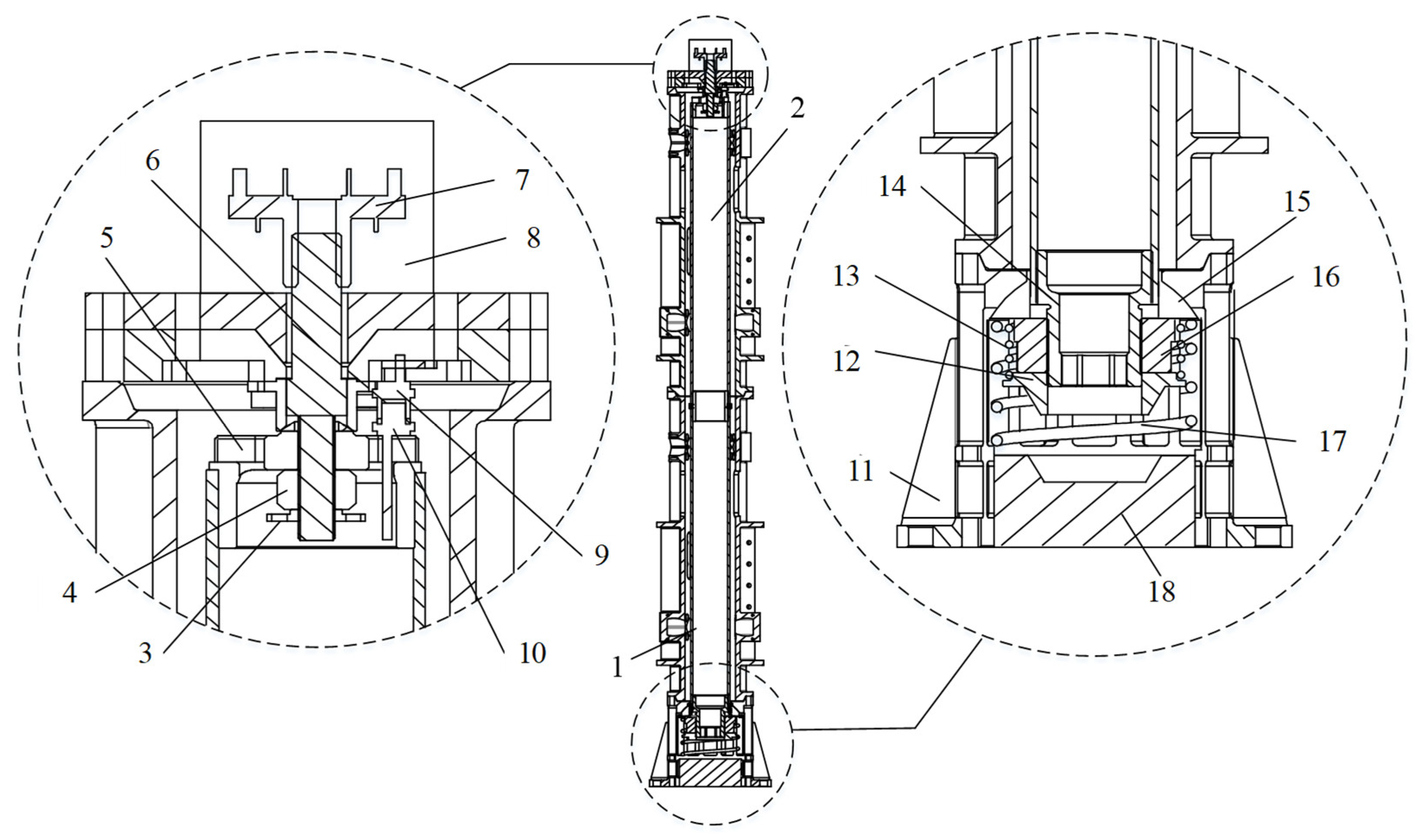
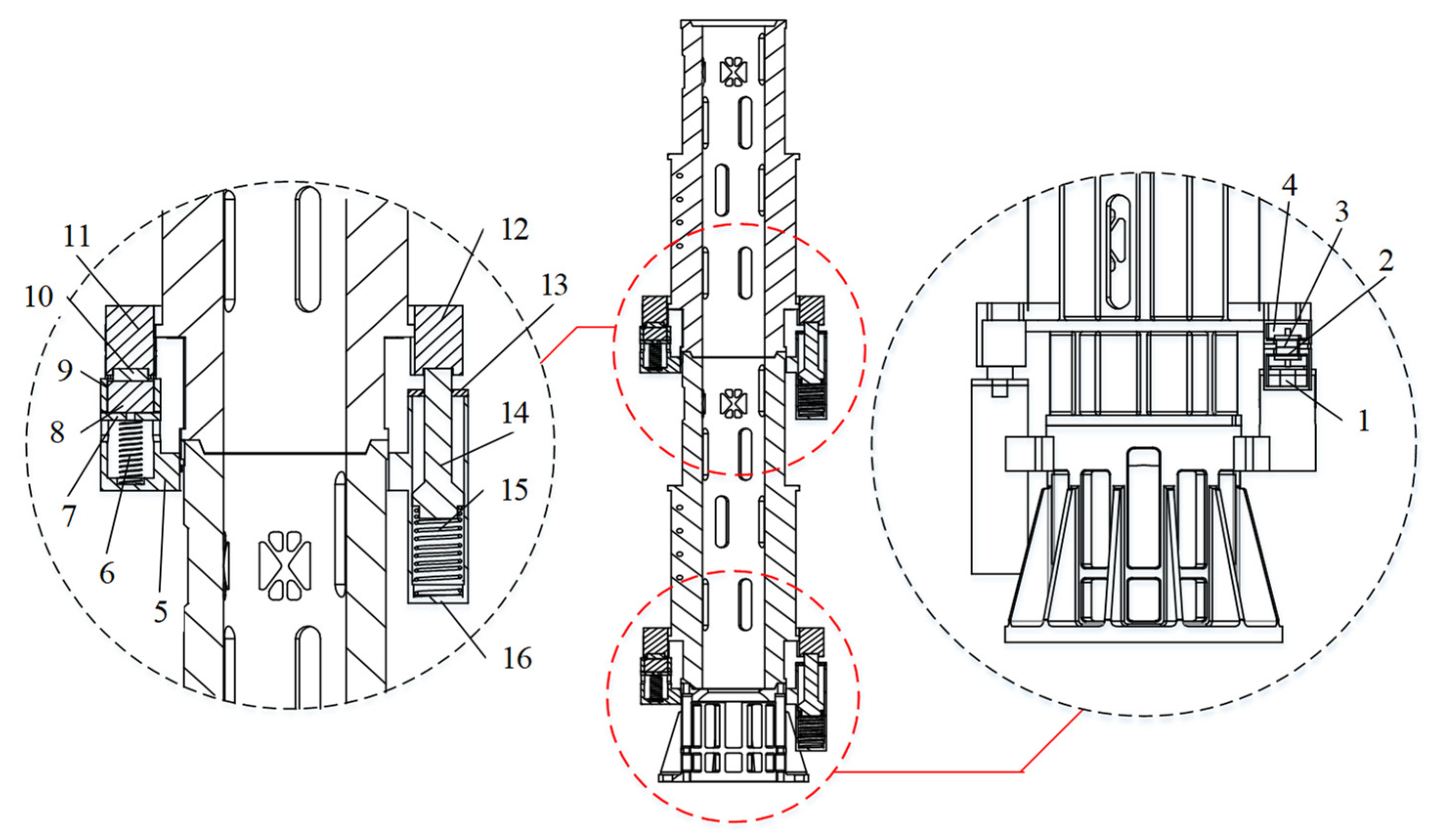
2.2. Compression Mechanism

The compression mechanism is the key component to achieving high load-bearing, and its structural form of compression and release directly determines high load-bearing, and the performance of the subsequent mechanism. The compression mechanism is mainly connected to the base and the satellite bearing column at the top through the guide bar, which is connected by thread, and the unlocker unlocks and releases. The detailed structure composition is shown in Figure 3.
The guide bar passes through the interior of the satellite load-bearing column to connect the force and displacement of the base section to the top unlocking section. The upper end of the guide bar is connected to the upper joint flange. The load-bearing screw passes through the upper joint flange. The lower end is connected to the preload nut and the locknut, and the upper end is connected to the non-self-locking nut. The non-self-locking nut is arranged in the unlocker, and the lower surface of the unlocker base plate is in contact with the upper surface of the uppermost satellite load-bearing column. The lower end of the guide bar is connected to the lower joint flange. The loading nut and the conical head nut form a threaded connection with the lower joint flange, and the loading nut contacts the spherical washer, which contacts the spherical surface of the fixed base.
In the pressed state, the loading nut squeezes the spherical washer by applying a pressing force. Therefore, a vertical downward reaction force is received from the fixed base, and the reaction force is transmitted to the guide bar. The guide bar applies a vertical downward preload force to the preload nut through the upper joint flange, so as to transmit the preload force to the unlocker. Then the force is transmitted to the load-bearing columns of the satellite through the lower base plate of the unlocker to realize the compression of the satellite group.
When unlocking and releasing, the unlocker is energized to release the circumferential restriction on the non-self-locking nut. The guide bar drives the load-bearing screw to move downward, freeing it from the thread constraint of the non-self-locking nut and releasing the compression force on the satellite group. The lower end of the guide bar allows the conical head nut to be embedded in the tapered groove of the retention base by the action of the retention spring, keeping the compression assembly in a fixed position in the microgravity environment.

2.3. Separation Mechanism

In order to realize the controllable separation function of the satellites, the inter-satellite controllable connection and separation mechanism is designed by using a combination of the electromagnetic connection and the spring ejection. Since only the load-bearing column in the satellite structure can bear the load, the electromagnetic connection assembly and the ejection separation assembly are both arranged at the contact connection of the load-bearing column. To ensure the uniformity of the force, four electromagnetic connection assemblies and ejection separation assemblies are added between each group of satellites, as shown in Figure 4.
The electromagnet in the electromagnetic connection assembly is in clearance fit with the inner hole of the lower base of the electromagnetic connection. The electromagnetic connection base has two symmetrical slots, and the magnet connection flange is designed with two symmetrical bosses that fit with its clearance. The electromagnet preload spring provides thrust to ensure that the electromagnet can maintain close contact with the iron block despite errors due to processing and assembly. The sliding sleeve guide rod in the ejection separation assembly is in clearance fit with the bore of the lower base of the electromagnetic connection.

3. Dynamic Model

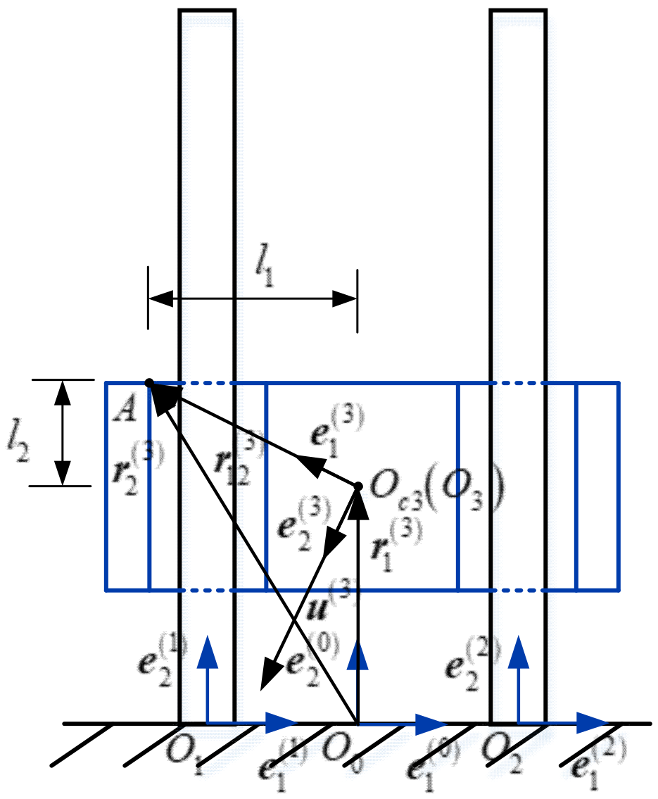
3.1. Natural Coordinate Method Based Rigid Body Satellite Dynamic Model

For rigid body satellites, the natural coordinate method is used to describe the planar unit. The natural coordinate method is used to describe the planar multi-body problem by selecting a series of representative “nodes”, whose Cartesian coordinates constitute the natural coordinates of the multi-body system together.
Figure 5 shows the representation of a planar rigid satellite based on the NCF method, whose motion position can be determined by two nodes, P 1 ( 3 ) and P 2 ( 3 ) , i.e., O c ( 3 ) and A , containing four generalized coordinates, as shown in Table 1.
The generalized coordinate vector of a planar rigid satellite can be expressed as:
q i = { r 1 ( i ) r 2 ( i ) } T
The natural coordinates corresponding to the planar rigid body satellite are represented by the matrix as:
Q i = ( x 1 ( i ) y 1 ( i ) x 2 ( i ) y 2 ( i ) ) T ( i = 1 , 2 , , n )
The total number of natural coordinates of the system is 2n, expressed in a natural coordinate array as:
Q = ( Q 1 T Q 2 T Q 2 n T ) T
Set n i as the normal base vector of the motion plane, select vector u i = n i × r 12 ( i ) as the reference vector, and u i is orthogonal to r 12 ( i ) and has the same modulus l ( i ) in the motion plane. With the base point P 1 ( i ) , define the conjoined base ( P 1 ( i ) ,   E ( i ) ) along and the direction r 12 ( i ) and u ( i ) , and its base vector is:
e 1 ( i ) = l i 1 r 12 ( i ) ,   e 2 ( i ) = l i 1 u ( i )
Decompose the vector diameter P ( i ) P 1 ( i ) of any point P ( i ) within the rigid body relative to the base point P 1 ( i ) along the directions r 12 ( i ) and u ( i ) as:
P ( i ) P 1 ( i ) = r ( i ) r 1 ( i ) = c 1 ( i ) r 12 ( i ) + c 2 ( i ) u ( i ) = l ( i ) ( c 1 ( i ) e 1 ( i ) + c 2 ( i ) e 2 ( i ) )
Representing each vector as a coordinate array in ( O 0 ,   E ( 0 ) ) , we can obtain:
R ( i ) = ( 1 c 1 ( i ) c 2 ( i ) c 1 ( i ) c 2 ( i ) c 2 ( i ) 1 c 1 ( i ) c 2 ( i ) c 1 ( i ) ) Q i
The mass of the rigid body is m i , and the vector diameter R ( i ) represented by Equation (6) is integrated within the range of the rigid body. We obtain the vector diameter R c ( i ) of the rigid body center of mass O c i relative to O 0 as:
R c ( i ) = 1 m i C ( i ) Q i d m i = D ( i ) Q i
The matrix D ( i ) is defined as:
D ( i ) = 1 m i C ( i ) d m i = ( 1 a 1 ( i ) a 2 ( i ) a 1 ( i ) a 2 ( i ) a 2 ( i ) 1 a 1 ( i ) a 2 ( i ) a 1 ( i ) )
Let the vector diameters of the point P ( i ) and the point P 1 ( i ) relative to the center of mass O c i be ρ ( i ) and ρ 1 ( i ) , and substitute P ( i ) P 1 ( i ) = ρ ( i ) ρ 1 ( i ) into Equation (5) to obtain:
1 m i ( ρ ( i ) ρ 1 ( i ) ) d m i = ρ 1 ( i ) = l ( i ) ( a 1 ( i ) e 1 ( i ) + a 2 ( i ) e 2 ( i ) )
After that A ( i ) = ( a 1 ( i ) a 2 ( i ) ) T can be represented by ρ 1 ( i ) in the coordinate array in ( P 1 ( i ) ,   E ( i ) ) as follows:
A ( i ) = l ( i ) 1 ρ 1 ( i )
The rate of change of vector r 12 ( i ) with respect to time t due to the rotation of a rigid satellite is:
r ˙ 12 ( i ) = ω ( i ) × r 12 ( i )
Let both sides be multiplied by the r 12 ( i ) vector, and express the vector r 12 ( i ) as a coordinate array to obtain the angular velocity expressed in natural coordinates as:
ω ( i ) = l ( i ) 2 [ ( x 2 ( i ) x 1 ( i ) ) ( y ˙ 2 ( i ) y ˙ 1 ( i ) ) ( y 2 ( i ) y 1 ( i ) ) ( x ˙ 2 ( i ) x ˙ 1 ( i ) ) ] = G ( i ) Q ˙ i
G ( i ) is a 1 × 4 row matrix, expressed as:
G ( i ) = l ( i ) 2 ( y 2 ( i ) y 1 ( i ) x 1 ( i ) x 2 ( i ) y 1 ( i ) y 2 ( i ) x 2 ( i ) x 1 ( i ) )
The rotational moment of inertia of the rigid satellite with respect to the center of mass O c i is J i . The coordinate array L ( i ) of the momentum of the rigid satellite with respect to the point O c i in ( O 0 ,   E ( 0 ) ) is:
L ( i ) = J i ω ( i ) = J i G ( i ) Q ˙ i
J i G ( i ) is the inertia matrix of the rigid satellite with respect to the center of mass O c i . Taking the derivative of Equation (5) with respect to t and G ˙ ( i ) Q ˙ i = 0 , we obtain:
L ˙ ( i ) = J i ( G ( i ) Q ¨ i + G ˙ ( i ) Q ˙ i ) = J i G ( i ) Q ¨ i
F ( i ) and M ( i ) are the coordinate array of the principal vector of the external force acting on the rigid satellite and the principal moment relative to the point O c i in ( O 0 ,   E ( 0 ) ) . Substituting Equations (7) and (15) into the momentum theorem and the momentum moment theorem for the center of mass, the dynamics equation of the rigid satellite plane motion is obtained as:
m i D ( i ) Q ¨ i = F ( i ) ,   J i G ( i ) Q ¨ i = M ( i )

3.2. Dynamic Model of Flexible Guide Bar Based on Floating Coordinate System Method

Due to the relative displacement between the mass points during the motion of the flexible body, no reference system can be completely fixed with the flexible body. Taking the floating coordinate system as the reference system, the actual motion of the flexible body can be understood as the synthesis of the large-scale rigid body motion of the floating coordinate system relative to the inertial coordinate system and the deformation motion relative to the floating coordinate system, and the flexible guide bar and its floating coordinate system are shown in Figure 6.
The floating coordinate system of the flexible guide bar is established at the midpoint of the fixed constraint at the bottom end, and the bottom end of the guide bar is a fixed constraint, so it does not produce a wide range of rigid body motion. The motion of the guide bar is its own flexible deformation.
The relative displacement u at the point P can be expanded by using the modal Ψ j ( x , y ) ( j = 1 , 2 , , n ) as:
u = j = 1 n Ψ j ( x , y )   q j ( t )
where q j ( t ) ( j = 1 , 2 , , n ) are the modal coordinates.
The mass matrix of the flexible body is:
M = ( M r r M r θ M r d M r θ M θ θ M θ d M r d M θ d M d d )
Each submatrix is defined as:
{ M r r = m E ,   M θ θ = D T J D M d d = ρ ^ V Ψ T Ψ d V ,   M r d = A ( 01 ) ρ ^ V Ψ d V M r θ = A ( 01 ) ( ρ ^ V ρ ˜ T d V ) D ,   M θ d = D T ( ρ ^ V ρ ˜ Ψ d V )
The stiffness matrix of the flexible body is:
K = V ( D ^ Ψ ) T E ^ D ^ Ψ d V
For a plane beam the stiffness matrix K can be simplified as:
K = 0 l ( Ψ 1 T Ψ 2 T ) ( E A 0 0 E I ) ( Ψ 1 T Ψ 2 T ) d x
The flexible guide bar generalized coordinate array Q 2 is represented by the rigid motion coordinates R O 1 , the azimuthal Euler angular coordinates θ and the modal coordinates Q f , denoted as:
Q 2 = ( R O 1 θ Q f ) T
The Lagrange multiplier method is applied to establish the kinetic equation as:
( M r r M r θ M r d M r θ M θ θ M θ d M r d M θ d M d d ) ( R ¨ O 1 θ ¨ Q ¨ f ) + K ( R O 1 θ Q f ) + Φ q T λ = ( Q R Q θ Q f )
Coupled with the constraint equation, the multi-body dynamic equation of the flexible guide bar is obtained as:
{ M Q ¨ + K Q + Φ q T λ = Q Φ ( Q , t ) = 0
In order to analyze the dynamics of the long-range guide separation mechanism, a contact collision model of the rigid body satellite and the flexible guide bar is required.

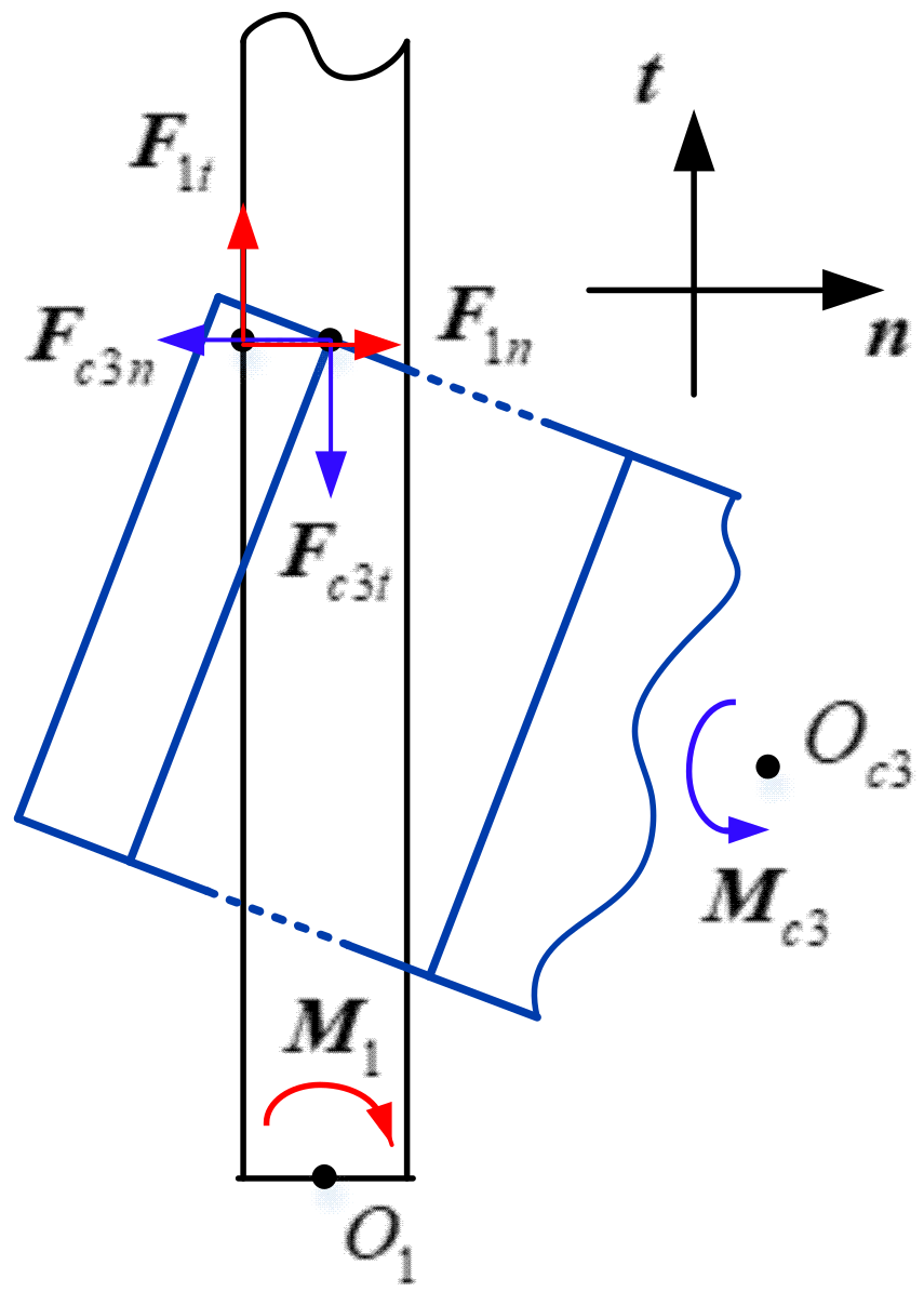
3.3. Contact Force Model

The geometric description and vector model of the contact between the satellite and the guide bar are as follows.

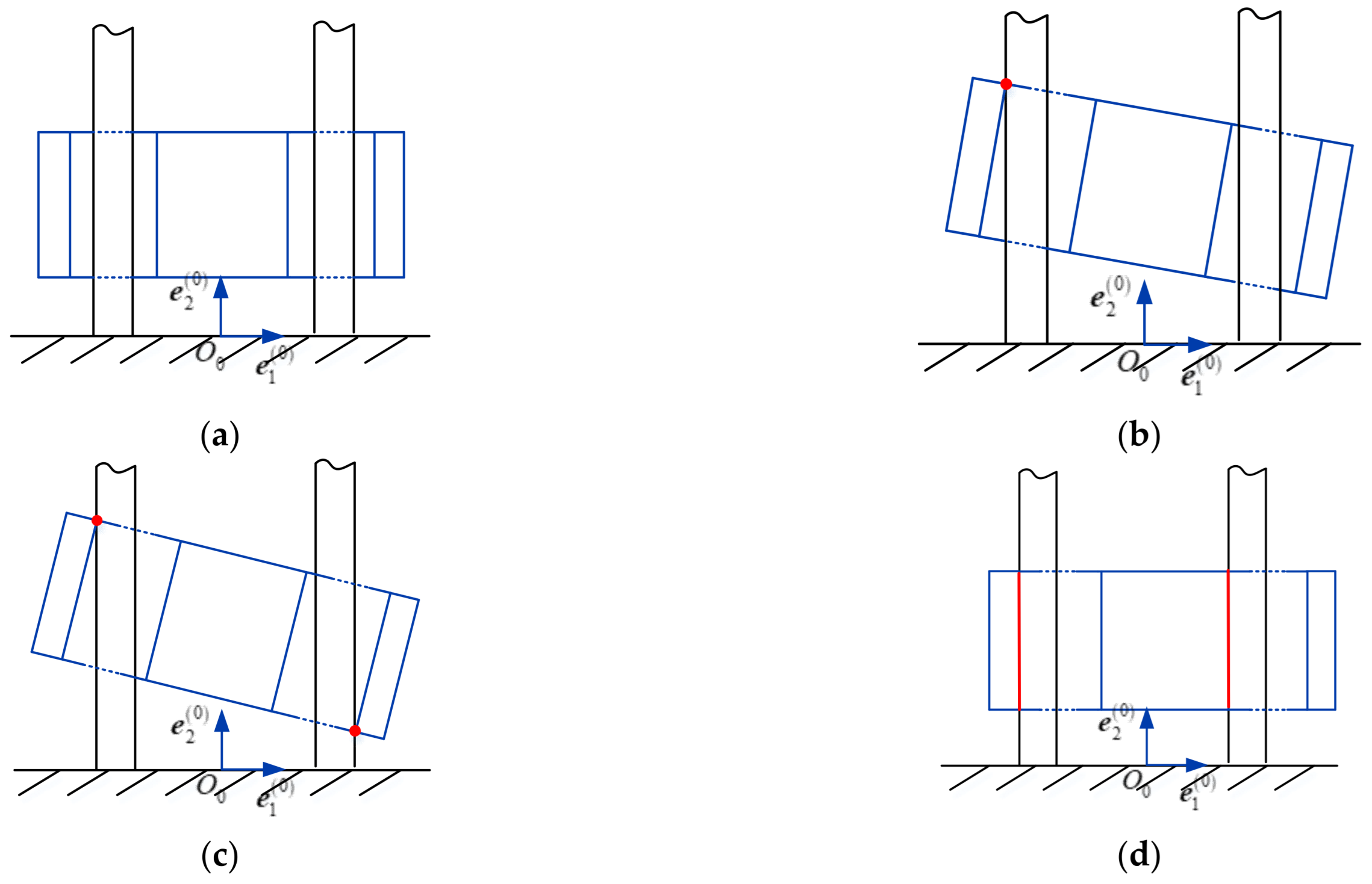
3.3.1. Contact Form of Rigid Body Satellite and Guide Bars

To represent the relationship between the rigid satellite and the flexible guide bar clearly, the clearance distance between the rigid satellite guide hole and the guide bar is enlarged. There are four possible forms of contact between the rigid satellite and the guide bars, as shown in Figure 7.
  • No contact between the two elements in the radial direction;
  • Point contact occurring between the side of the guide bar and one endpoint of the satellite guide hole;
  • Point contact occurring between the sides of two guide bars and two endpoints of the satellite guide hole;
  • The sides of the two guide bars overlap with the sides of the satellite guide holes leading to line contact;

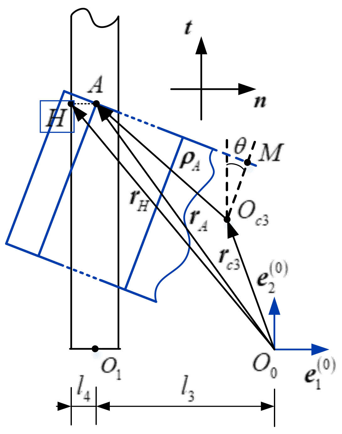
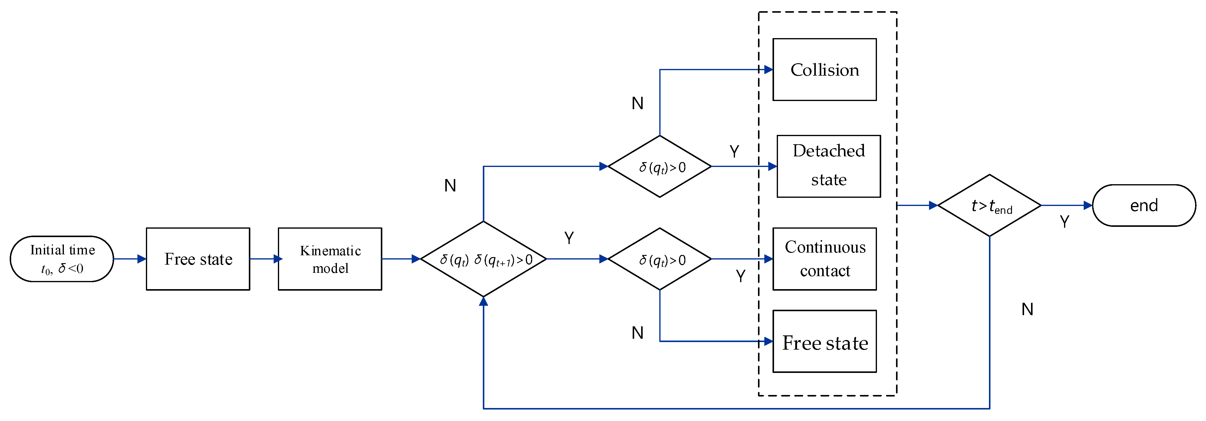
3.3.2. Judgment Basis of Contact State

The contact forms between the rigid satellite and the guide bars are complex and varied. How to discern the contact and separation state between the two elements is a key issue in the study of the guided separation process.
The prerequisite to determining whether and when the contact between the satellite and the guide bar occurs is to find the first point where the contact occurs, i.e., to determine the potential contact point, so as to establish the expression of the embedding depth between the two elements caused by the contact deformation. A simplified model for solving the embedding depth is shown in Figure 8. The embedding depth is solved for the left guide hole of the satellite as an example, and the situation is similar on the other side.
Analyzing the simplified model, it is clear that the potential contact points on the two elements must be at the endpoints of the edges of the guide holes. ( O 0 ,   e ( 0 ) ) is the inertial coordinate system, point O 1 is the midpoint of the edge of the guide bar, point A is the upper left endpoint of the guide hole on the left side of the satellite, point H is the projection of point A on the outside of the guide bar, point O c 3 is the center of mass of the satellite, point M is the midpoint of the upper edge of the satellite, and θ is the angle between the short side of the satellite and the vertical direction, at any moment point O c 3 = ( x 3   ,   y 3 ) T , M = ( x m   ,   y m ) T . Take vector r c 3 from the O 0 of the inertial coordinate system to the center of mass O c 3 of the satellite, vector r A from O 0 to the upper left endpoint A of the left guide hole of the satellite, vector r H points from O 0 to H , and vector ρ A points from the center of mass of the satellite O c 3 to point A .
Vector r A and vector r H can be expressed as follows:
{ r A = r c 3 + A 3 ρ A = ( x c 3 l 1 cos θ + l 2 sin θ ) n + ( y c 3 + l 1 sin θ + l 2 cos θ ) t r H = r P + A 1 ρ H = ( l 3 l 4 ) n + ( y c 3 + l 1 sin θ + l 2 cos θ ) t
Because of:
{ y M y c 3 = l 2 cos θ x M x c 3 = l 2 sin θ
We can obtain:
{ r A = [ x M 2 x c 3 l 1 l 2 ( y M y c 3 ) ] n + [ y M + l 1 l 2 ( x M x c 3 ) ] t r H = ( l 3 l 4 ) n + [ y M + l 1 l 2 ( x M x c 3 ) ] t
The embedding depth can be expressed as:
δ = | r A n | | r H n | = | x M 2 x c 3 l 1 l 2 ( y M y c 3 ) | ( l 3 + l 4 ) = l 1 l 2 ( y M y c 3 ) + 2 x c 3 x M ( l 3 + l 4 )
The embedding depth δ is a function of coordinates of point O c 3 and point M , i.e., δ = δ ( O c 3   ,   M ) .
The modeling of the contact collision force is the key to describing the interaction force of the guide and separation mechanism. According to the different relative motion states between the rigid body satellite and the flexible body guide bar, the contact collision force also has three forms. When two elements are in contact with each other, a contact force is generated between the elements, which is F c . The contact force is F c decomposed into the collision force F n in the normal direction of the contact point and the friction force F t in the tangential direction, as shown in Figure 9, which transforms the contact force problem into the collision and friction problem during the motion of the mechanical elements.
Obviously, the points of action of the contact forces acting at contact points A and H are at different locations. To establish a unified expression, the contact force is converted into a contact force acting on the center of mass of the satellite and the guide bar. During the conversion of the contact force, an additional moment of action is generated for the satellite and the guide bar, which acts equivalently at the center of mass.
{ M c 3 = F c 3 n × R O c 3 A + F c 3 t × R O c 3 A M 1 = F 1 n × R O 1 H + F 1 t × R O 1 H
Since the normal collision force model and the tangential friction force model contain relative velocity terms, the relative velocities of the two elements moving in contact with each other are also determined in order to calculate the normal collision force and the tangential friction force between the two elements.
Derivation of Equation (25) yields the velocity at the point of contact as:
{ r ˙ A = r ˙ c 3 + A ˙ 3 ρ A + A 3 ρ ˙ A r ˙ H = r ˙ P + A ˙ 1 ρ H + A 1 ρ ˙ H
The relative velocity of the contact point can be expressed as:
v r = r ˙ A r ˙ H
Projecting the relative velocity to the normal and tangential directions of the contact point, the relative normal velocity and relative tangential velocity can be obtained as:
{ v r n = v r n v r t = v r t
By substituting the relative velocities of the contact points into the normal collision force model and the tangential friction model, the contact forces can be obtained.
Based on the Hertz contact model, a contact force model considering hysteresis damping called the L-N nonlinear spring damping model was proposed by Lankarani and Nikravesh.
The contact force is expressed using the L-N contact force model as:
F n = K δ n + D δ ˙
where
D = 3 K ( 1 C e 2 ) δ n 4 δ ˙ ( )
where K is the nonlinear spring stiffness coefficient, δ is embedding depth, D is generalized damping coefficient, δ ˙ is collision relative velocity, and Ce is recovery coefficient, δ ˙ ( ) is relative velocity at the initial moment of contact.
Substituting the expression for the generalized damping factor, the contact force can be obtained as:
F n = K δ n [ 1 + 3 ( 1 C e 2 ) δ ˙ 4 δ ˙ ( ) ]
This contact force model is suitable for contact between satellites and guide bars, which has low-speed collision and large recovery coefficient.
Figure 10a shows the classical model for expressing friction, which fits Coulomb friction model. Friction is proportional to the normal contact force, and when the normal contact force is constant, the friction is constant and the direction is opposite to the speed of motion. Friction can be expressed as:
F t = μ | F n | sgn ( v )
where μ is the friction coefficient between the surfaces of two objects, Ft is tangential friction, and v is the relative velocity between the two objects.
However, the Coulomb friction model does not reflect the actual state of the object where friction occurs properly. The numerical jump in the friction force when the velocity of motion is zero also makes the solution difficult.
The Coulomb friction model with modified coefficient introduced is shown in Figure 10b, and it can be expressed as:
F t = c f c d F n v t v t
where cf is coefficient of friction between the two surfaces and vt is the relative velocity between the two objects.
The improved Coulomb friction model introduces a dynamic modified coefficient, cd, which is related to the relative velocity between objects, and its expression is as follows:
c d = { 0 i f   v t v 0 v t v 0 v 1 v 0                 i f   v 0 v t v 1 1 i f   v t v 1
where v1 and v0 are relative velocity thresholds.

3.4. Separation Dynamic Model with Contact Collisions

The relative motion of the satellite and the guide bar is expressed in four states: free state, collision state, detached state, and contact state. The free state is defined as the state in which the satellite and the guide bar are separated from each other with no collision or contact. In this state, there is no contact force between the inner hole of the satellite load-bearing column and the guide bar. The contact state is defined as the state in which the surface deformation occurs between the inner hole of the satellite load-bearing column and the outer surface of the guide bar by mutual extrusion. The contact state generates contact force, which can be decomposed into normal collision force due to normal relative motion and tangential friction force due to tangential motion. The detached state and the collision state are two transition stages. The detached state is the transition stage from the contact state to the free state. The collision state is the transition stage from the free state to the contact state.
When the free state ends, the motion state is changed into the collision state. When the collision state ends, the motion state is changed into the contact state. The next moment after the end of the contact state, the motion state is transferred to the detached state. The next moment after the end of the detached state, the motion state is immediately transferred to the free state, and so on. Therefore, it is necessary to judge the relative motion state of the moving subelements, because each change of motion state means the beginning of contact or separation between the moving subelements.
Firstly, the relative motion state at the current moment is determined by the embedding depth δ   derived in the previous section.
When δ < 0, the satellite and the guide bar have not been in contact and the relative motion state is free state.
When δ = 0, the satellite and the guide bar begin to collide or begin to separate.
When δ > 0, the satellite continuously contacts with the guide bar.
The relationship between δ of two adjacent time steps and the relative velocity between the two in the collision normal direction at the current moment are used to further determine the switching of the motion state.
{ δ ( q t ) δ ( q t + 1 ) > 0   and   δ ( q t ) < 0   free   state   δ ( q t ) δ ( q t + 1 ) < 0   and   δ ( q t ) < 0   collision   state   δ ( q t ) δ ( q t + 1 ) < 0   and   δ ( q t ) > 0   detached   state   δ ( q t ) δ ( q t + 1 ) > 0   and   δ ( q t ) > 0   continuous   contact  
The initial relative motion state of the satellite and the guide bar is the free state. In the process of separation motion, the flow chart of the judgment method to discern the relative motion state of the satellite and the guide bar is shown in Figure 11.
In order to introduce the contact forces into the flexible multi-body dynamics equation and establish a unified form of the dynamics equation, introduce a step function u( δ ).
u ( δ ) = { 0 ,   δ < 0 1 ,   δ 0
The contact force Fc can be expressed as:
F c = u ( δ ) ( F n + F t )
Then, the dynamic model of satellite guided separation system with contact interaction can be obtained as:
{ M q ¨ + K q + Φ q T λ = Q c + F c Φ ( q , t ) = 0
From the dynamic model, it can be seen that the main factors affecting the motion parameters in the guided satellite separation process are the length of the load-bearing column, the inner hole diameter of the load-bearing column, the diameter of the guide bar, and the initial velocity and initial angular velocity of the satellite. The subsequent content will present dynamics simulation analysis and experimental investigation of the key factors.

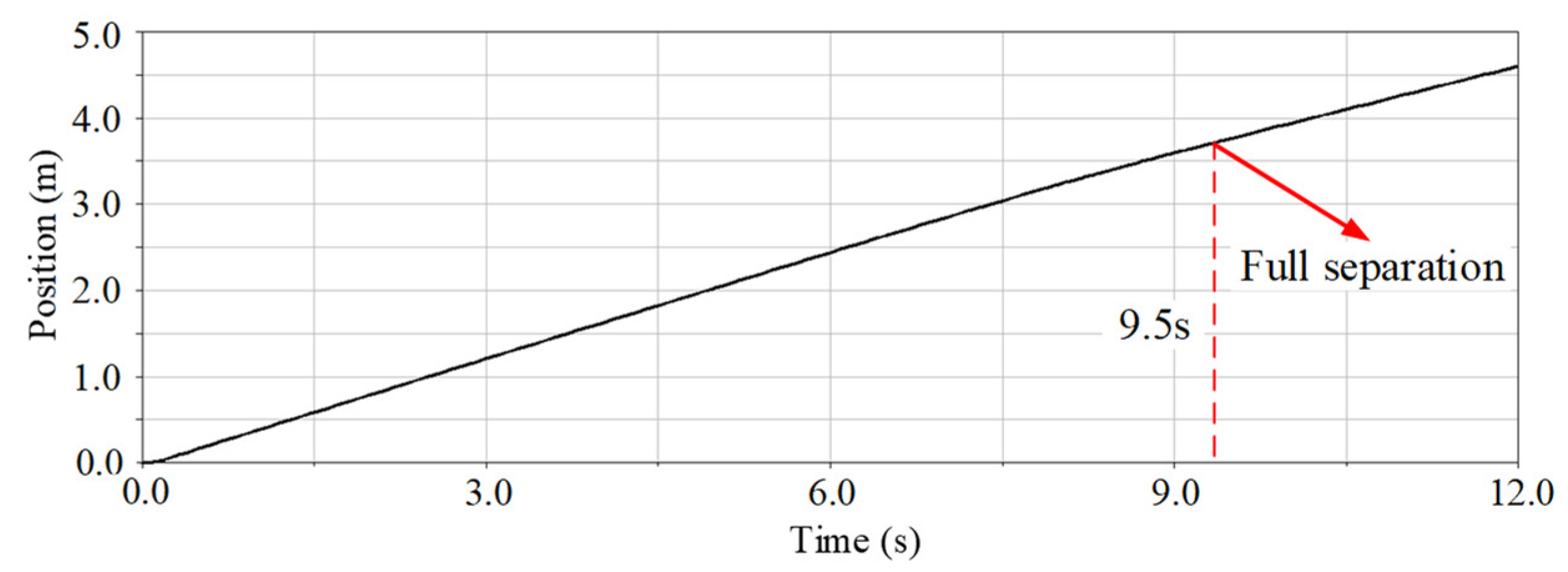
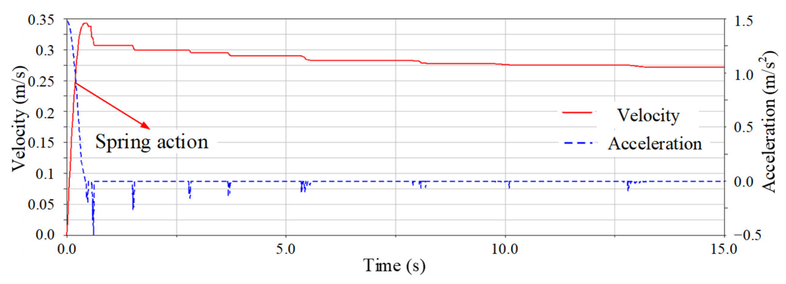
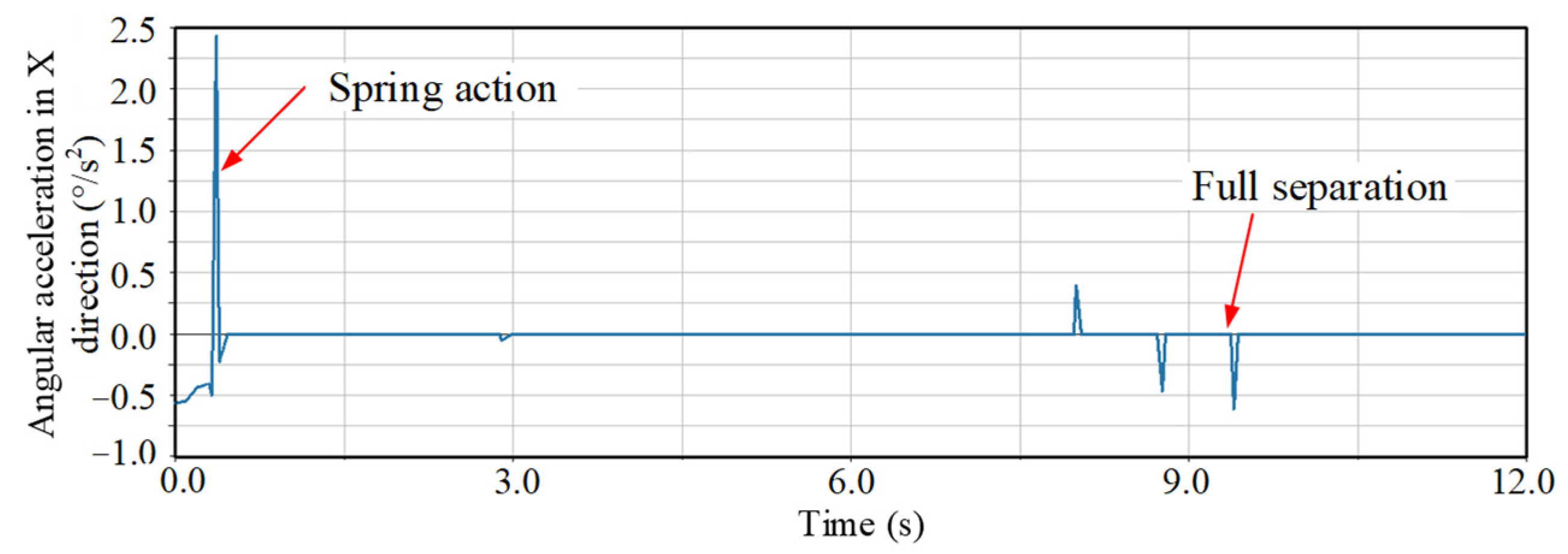
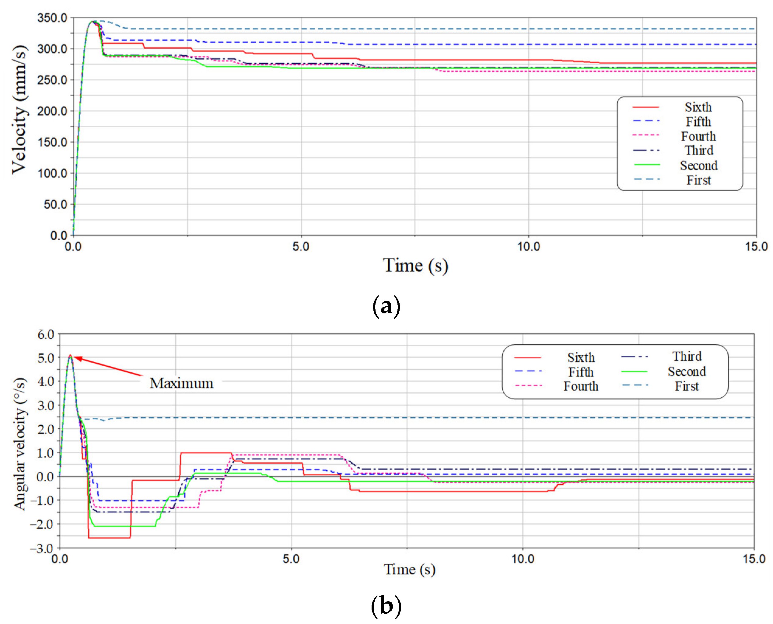
4. Separation Characteristics Simulation

Since the sixth satellite is located at the bottom and released last, it has the longest travel inside the guide bars. So, we select the sixth satellite to analyze the separation characteristics. As shown in Figure 12, it spends about 9.5 s for the satellite to be completely separated from the guide bar with a length of 3.85 m. The separation velocity and acceleration are shown in Figure 13. The separation speed fluctuates due to the collision between the satellite and the guide bars. The maximum acceleration is about 1.5 m/s2. Due to the friction and collision with the guide rod, several smaller negative accelerations occur on the z-axis. The angular acceleration around the x-axis of the satellite is shown in Figure 14. Because of the stiffness error of the spring, the satellite has a negative angular acceleration around the x-axis.
Figure 15 shows comparison of the separation characteristics of the six satellites. The maximum velocity of the satellites is all 0.347 m/s due to the same spring. The satellites collide with the guide bars several times, causing the velocity to decrease. Because of the different number of collisions, there is a difference in the velocity after separation. The spring difference leads to a large angular velocity of the satellite, which is well suppressed after many contact collisions with the guide bars. However, due to the short guided stroke of the first satellite, the angular velocity reached 2.47°/s at separation, while the other satellites kept it within 1°/s.

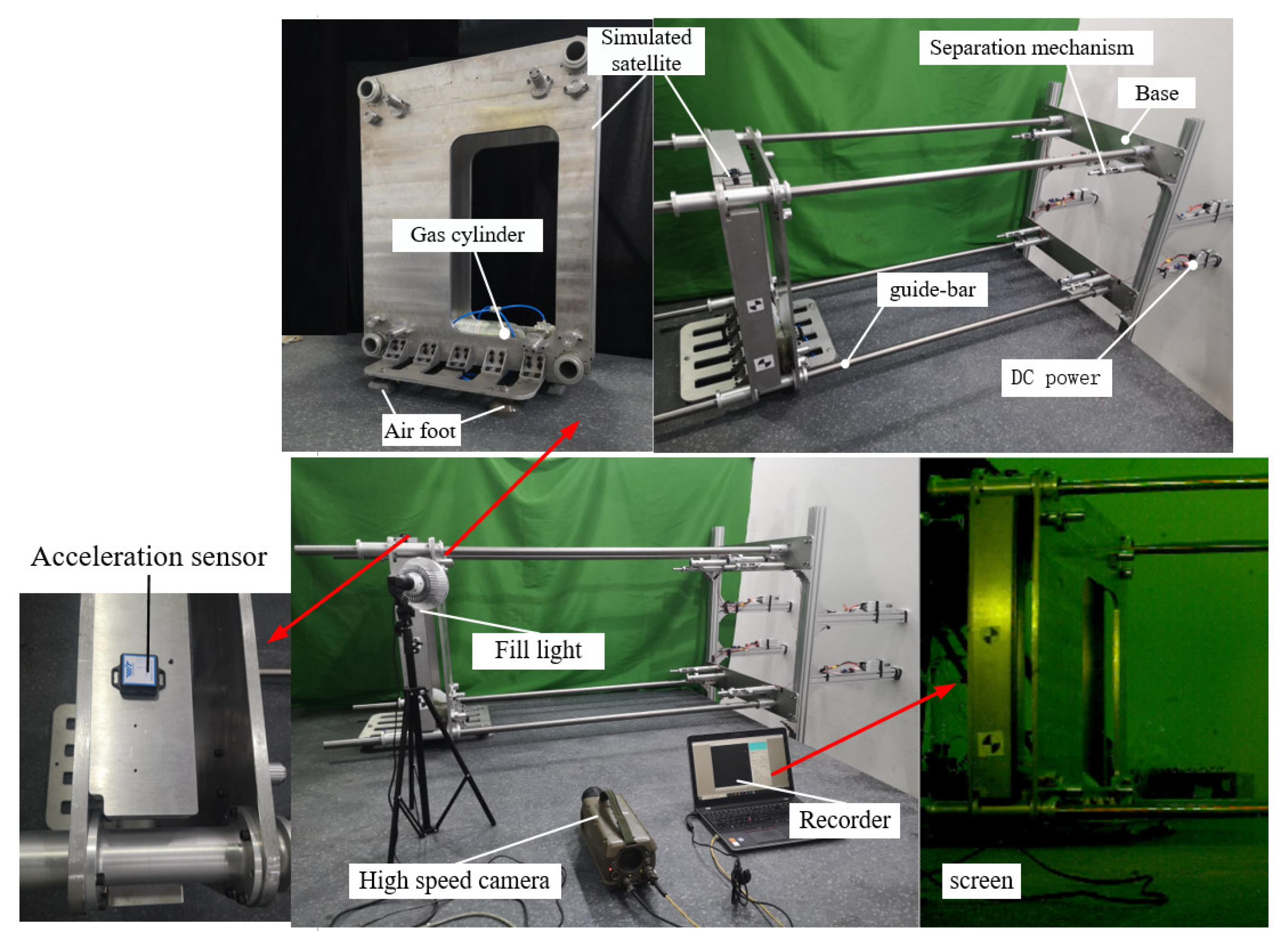
5. Experiment Investigation

To investigate the function and characteristics of the compression and release device, experiments were conducted on the compression and unlocking characteristics, and the dynamic characteristics of the satellite release, respectively.

5.1. Compression and Unlocking Characteristics Experiment

5.1.1. Compression Test

In order to check whether the structures in the system can withstand the sinusoidal and random vibration environment during the rocket launch, and to investigate the defects in structural design and material selection as well as processing and assembly, the sinusoidal and random vibration tests were conducted on the system. The two test satellites were mounted on the adapter table and connected by the centralized compression and release mechanism. The centralized compression and release mechanism applied a compression force of 45 kN to keep the system in a compressed state, as shown in Figure 16. The vibration amplitude is 1.17 mm when the sine vibration frequency is 5~8 Hz. The vibration amplitude is 0.3 g when the frequency is 8~100 Hz. The random vibration input conditions are shown in Table 2.
The results of the vibration experiments are shown in Figure 17. Under the action of sinusoidal vibration with the frequency range of 5 to 100 Hz, the x-direction and y-direction resonate at 29.1 Hz and 31.2 Hz, respectively, producing a maximum response of 4.53 g and 4.29 g. The z-direction resonates at 77.6 Hz with a maximum response of only 0.68 g, reflecting the good compression performance. According to the static strength analysis, it is known that the compression and release device can withstand an acceleration response of 7.5 g in the z-direction, which verifies that the compression and release device can be reliably locked under the given vibration conditions. In the frequency range from 10 to 2000 Hz, the resonance occurs at 585 Hz and 580 Hz in the x-direction and y-direction respectively by random vibration, and the maximum response is 0.95 g2/Hz and 0.81 g2/Hz respectively. The resonance occurs at 530 Hz in the z-direction, and the maximum response is only 0.09 g2/Hz. Therefore, the experiments reflect the good compression performance.

5.1.2. Unlocking Experiment

The successful unlocking of the centralized compression and release device is important for the smooth separation of the satellite in orbit. Especially after being subjected to complex vibration environment, it can release the compression force and realize the unlocking function. The unlocking separation experiment is shown in Figure 18.
The counterweight suspension is used to simulate the space microgravity environment. Each satellite is connected to the counterweight at four corners through wire ropes and fixed pulleys. The mass of the counterweight is equal to that of the test satellite and is proportionally distributed according to the position of the center of mass of the test satellite. When the centralized compression and release mechanism is unlocked, the testing satellite is separated along the vertical direction under the thrust of the separation spring. The unlocking process of the centralized compression and release mechanism starts at the moment of SMA wire is energized and ends at the moment when the compression force of the device on the satellite group is released to zero. The time experienced in this process is defined as the unlocking time. In the practical test, it is difficult to identify the moment when the compression force is released to zero. So, the moment when the load-bearing screw is disengaged from the unlocker is used as the endpoint. The average unlocking and releasing time was 312 ms after three tests with input power of 5 A supplied to the unlocker from a DC power. This experiment indicates that the centralized compression and release mechanism can still unlock and release the pressing force at a predetermined time to achieve the pressing and releasing function after experiencing a complex vibration environment.

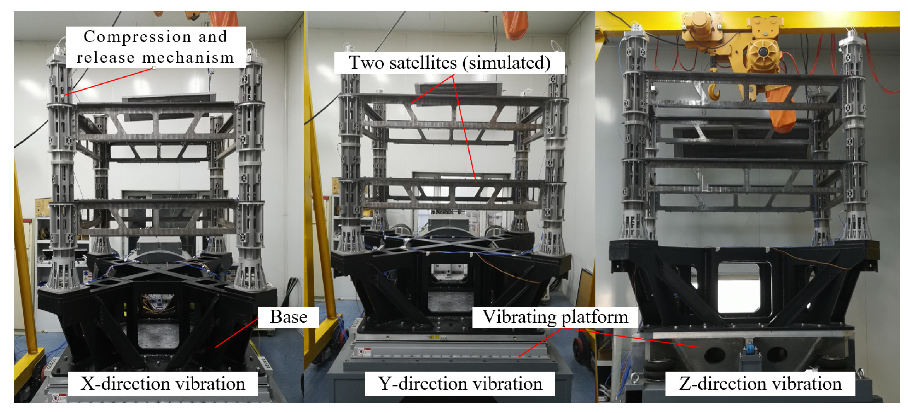
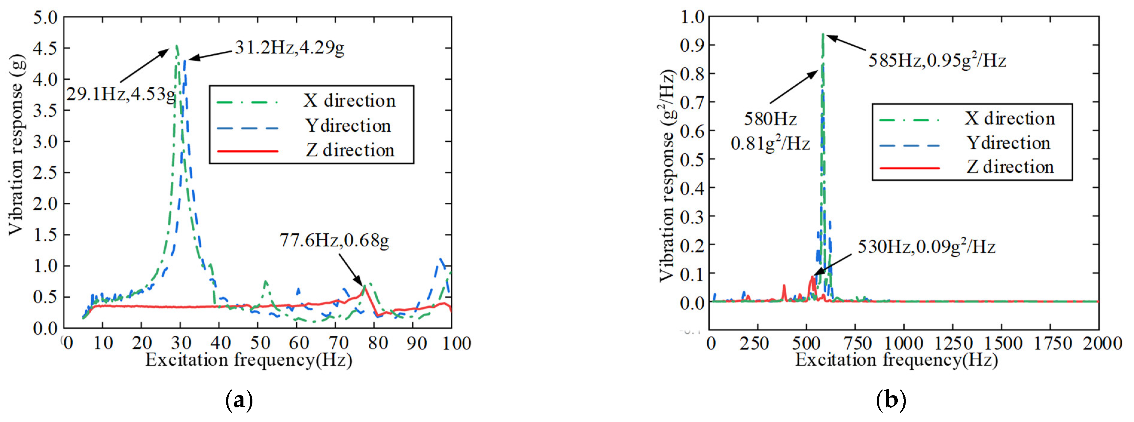
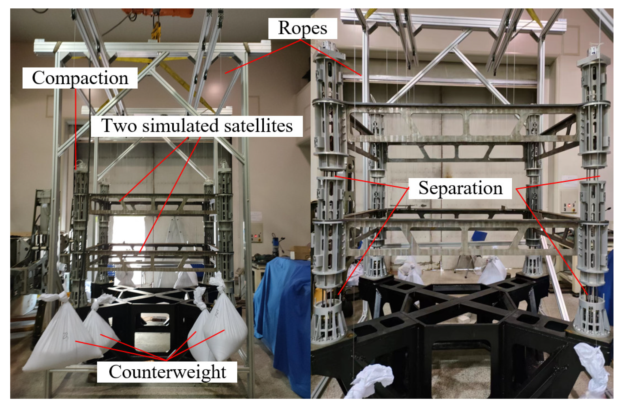
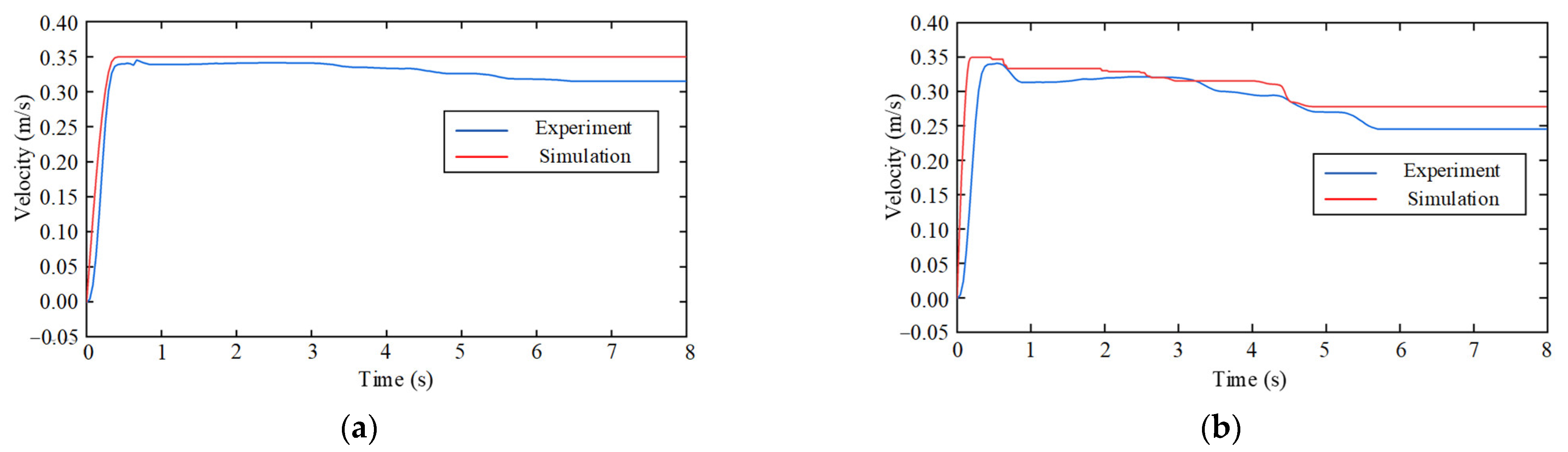
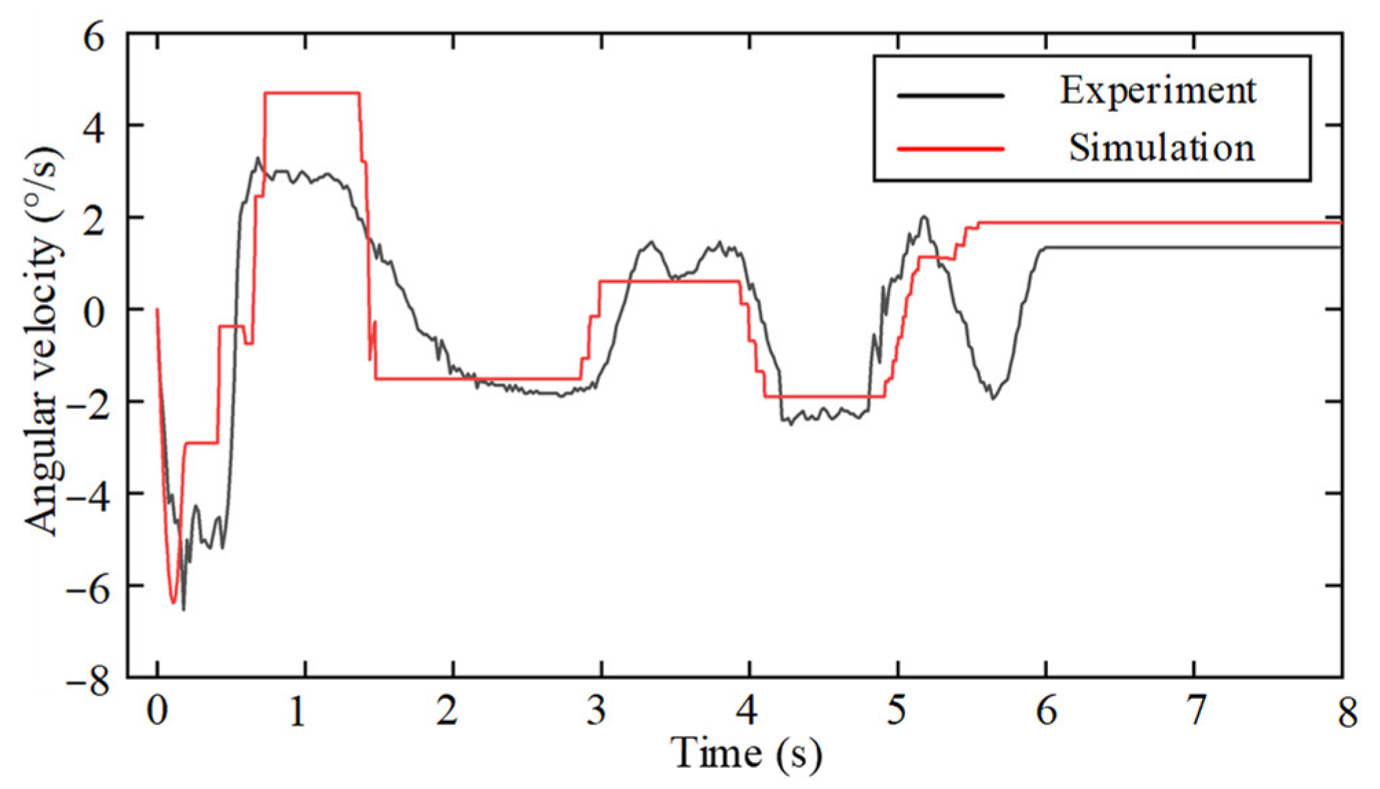
5.2. Separation Characteristics Experiment

The scaled-down prototype and experimental setup are shown in Figure 19. The satellite pedestal is fixed on the side of the marble platform. The four electromagnetic actuators and the ejection separation assembly are mounted at the four corners of the base attachment plate. The satellite is located above the air-floating platform to eliminate the effect of friction during the separation process. The gas cylinder is mounted inside the satellite The satellite is kept in the initial position by the suction of the electromagnetic actuator to overcome the thrust of the separation spring. A high-speed camera records the whole process of the motion of the target point located on the satellite. The angular velocity sensor is mounted on the satellite to record the angular velocity.
Figure 20 illustrates the test results of the separation speed. Figure 20a shows that the maximum separation velocity of the satellite is 0.345 m/s. The satellite collides with the guide bars, resulting in a slight decrease in velocity. The velocity decreases to 0.315 m/s when the satellite is completely detached from the guide bars. The complete detachment velocity 0.315 m/s of the satellite is smaller than the simulation result 0.35 m/s. The difference of 0.035 m/s is due to the tilt of the placed spring, which leads to a shortening of the stroke. The difference in the spring stiffness coefficient causes the satellite to develop an angular velocity around the x-axis. The small bending of the guide bars caused by the gravity leads to an increase in the probability of collision occurrence, while the friction between the mechanisms also leads to energy loss. Figure 20b shows the experimental results of the separation spring under a 10% error condition. The maximum separation velocity of the satellite is 0.34 m/s. The satellite collides with the guide bars, causing a stepwise decrease in velocity. The velocity decreases to 0.252 m/s when the satellite is completely detached from the guide bars. The complete separation velocity 0.252 m/s of the satellite is smaller than the simulated value 0.278 m/s. The experimental results show that the four-guide-bar corner arrangement ensures the satellite separate smoothly and the complete separation velocity loss is small. Even under the large spring error, a reliable release can still be successfully achieved.
A large angular velocity of separation causes satellite spin and brings adverse effects on the subsequent missions. Considering the case of a 10% error in the spring stiffness coefficient, the separation experiment results are shown in Figure 21. The additional disturbance moment from the spring inconsistency makes the satellite collide several times during the separation process. The angular velocity decreases after each collision. The trend of the experimental results and simulation results are consistent. The angular velocity obtained by dynamics simulation is 1.88°/s. The angular velocity at the moment of satellite detaching from the guide bars in the experimental results is 1.34°/s. This shows that the separation angular velocity is reduced due to the contact collision between the guide bars and the satellite.
The separation experimental results show that both separation velocity loss of the satellite and the disturbance angular velocity are small under the four-guide-bar corner arrangement. Thus, the good separation characteristics are achieved successfully.

6. Conclusions

According to multi-satellite launch requirements and mission targets, a compression and release scheme with four guide bars arranged at corners is proposed. A new compression and release device is designed correspondingly, which achieves good compression and separation characteristics. In the frequency interval of 5~100 Hz, under the action of sinusoidal vibration, the maximum responses in the x, y, and z directions are 4.53 g, 4.29 g, and 0.68 g, respectively, indicating that the compression and release device can be reliably locked under the given vibration conditions. The maximum responses in the x, y, and z directions were 0.95 g2/Hz, 0.81 g2/Hz, and 0.09 g2/Hz, respectively, under the action of random vibration of 10 to 2000 Hz, reflecting good compression performance. The average time of unlocking and releasing is only about 312 ms. This verifies that the compression and separation device can still unlock and fast release after experiencing the complex vibration. The maximum velocity of the satellite release process is 0.345 m/s, and the complete separation velocity is 0.315 m/s. Under 10% spring error, the maximum satellite separation velocity is 0.34 m/s, the complete release velocity is reduced to 0.252 m/s, and the separation angle is 1.34°/s. The results show that the configuration of arranging guide bars at the four corners makes the satellite separate smoothly, and the complete separation velocity loss is small. Reliable release and low interference angular velocity are successfully achieved, even with large spring errors.

Author Contributions

Conceptualization, H.Y. and F.Y.; methodology, Y.Z. and Q.Z.; software, Y.Z. and H.L.; validation, X.Y., H.L. and Y.Z.; formal analysis, F.Y.; investigation, H.L. and Q.Z.; resources, H.Y.; data curation, H.L.; writing—original draft preparation, Y.Z.; writing—review and editing, X.Y. and Q.Z.; visualization, X.Y. and F.Y.; supervision, F.Y. and Q.Z.; project administration, H.Y.; funding acquisition, H.Y. All authors have read and agreed to the published version of the manuscript.

Funding

This research was funded by the National Natural Science Foundation of China (52075118).

Institutional Review Board Statement

Not applicable.

Informed Consent Statement

Not applicable.

Data Availability Statement

Not applicable.

Acknowledgments

The author would like to thank the reviewers and the editors for their valuable comments and constructive suggestions that helped to improve the paper significantly.

Conflicts of Interest

The authors declare no conflict of interest.

References

  1. Jia, L.; Zhang, Y.; Yu, J.; Wang, X. Design of Mega-Constellations for Global Uniform Coverage with Inter-Satellite Links. Aerospace 2022, 9, 234. [Google Scholar] [CrossRef]
  2. Zhang, Z.; Deng, L.; Feng, J.; Chang, L.; Li, D.; Qin, Y. A Survey of Precision Formation Relative State Measurement Technology for Distributed Spacecraft. Aerospace 2022, 9, 362. [Google Scholar] [CrossRef]
  3. Luo, Y.; Jiang, X.; Zhong, S.; Ji, Y.; Sun, G. Multisatellite Task Allocation and Orbit Planning for Asteroid Terminal Defence. Aerospace 2022, 9, 364. [Google Scholar] [CrossRef]
  4. Zhao, X.; Zhao, C.; Li, J.; Guan, Y.; Chen, S.; Zhang, L. Research on Design, Simulation, and Experiment of Separation Mechanism for Micro-Nano Satellites. Appl. Sci. 2022, 12, 5997. [Google Scholar] [CrossRef]
  5. Yang, F.; Yue, H.; Wang, G.; Tu, Q.; Wang, W. The design and analysis of picosatellite deployer with controllable release function. In Proceedings of the 2017 IEEE International Conference on Information and Automation (ICIA), Macao, China, 18–20 July 2017; pp. 548–554. [Google Scholar] [CrossRef]
  6. Zhao, Y.; Yue, H.; Yang, F.; Zhu, J. A High Thrust Density Voice Coil Actuator with a New Structure of Double Magnetic Circuits for CubeSat Deployers. IEEE Trans. Ind. Electron. 2022, 69, 13305–13315. [Google Scholar] [CrossRef]
  7. Kwon, S.-C.; Son, J.-H.; Song, S.-C.; Park, J.-H.; Koo, K.-R.; Oh, H.-U. Innovative Mechanical Design Strategy for Actualizing 80 kg-Class X-Band Active SAR Small Satellite of S-STEP. Aerospace 2021, 8, 149. [Google Scholar] [CrossRef]
  8. SXRS-3_Mission at-a-glance [EB/OL]. Available online: https://spaceflight.com/sp-missions/sxrs-3/ (accessed on 4 August 2022).
  9. Krebs, G.-D. “Orbital Launches of 2021”. Gunter’s Space Page. Available online: https://space.skyrocket.de/doc_chr/lau2021.htm (accessed on 4 August 2022).
  10. Niccolai, L.; Bassetto, M.; Quarta, A.A.; Menggali, G. A review of Smart Dust architecture, dynamics, and mission applications. Prog. Aerosp. Sci. 2019, 106, 1–14. [Google Scholar] [CrossRef]
  11. Filippi, E.; Attouoman, H.; Conti, C. Pyroshock simulation using the alcatel etca test facility. In Proceedings of the First European Conference on Launcher Technology, Toulouse, France, 14–16 December 1999. [Google Scholar]
  12. Drossel, W.G.; Kunze, H.; Bucht, A.; Weisheit, L.; Pagel, K. Smart3-Smart materials for smart applications. Procedia Cirp 2015, 36, 211–216. [Google Scholar] [CrossRef]
  13. Zhang, Y.; Yang, L.; Zhu, Y.; Huang, H.; Cai, W. An investigation of on-orbit release with inter-satellite electromagnetic force. Aerosp. Sci. Technol. 2015, 45, 309–315. [Google Scholar] [CrossRef]
  14. Yang, F.; Yue, H.; Zhang, Y.; Peng, J.; Deng, Z. Research on a low-impact unlocking trigger device of heavy load based on shape memory alloy fiber. Adv. Mech. Eng. 2017, 9, 1687814017724089. [Google Scholar] [CrossRef]
  15. Zhang, X.; Yan, X.; Yang, Q. Design and Experimental Validation of Compact, Quick-Response Shape Memory Alloy Separation Device. J. Mech. Des. 2013, 136, 011009. [Google Scholar] [CrossRef]
  16. Bongers, E.; Koning, J.; Konink, T. Robustness improvement of ARA Kevlar Holddown restraint cables. In Proceedings of the 15th European Space Mechanisms & Tribology Symposium ESMATS, Noordwijk, The Netherlands, 25–27 September 2013. [Google Scholar]
  17. Peffer, A.; Denoyer, K.; Fosness, E.; Sciulli, D. Development and transition of low-shock spacecraft release devices. In Proceedings of the 2000 IEEE Aerospace Conference, Proceedings (Cat. No. 00TH8484), Big Sky, MT, USA, 25 March 2000; IEEE: New York, NY, USA, 2000; Volume 4, pp. 277–284. [Google Scholar]
Figure 1. Flat satellite: 1—solar panel; 2—reinforced support; 3—load-bearing column; 4—Main structure and devices; 5—antenna.
Aerospace 09 00446 g001
Figure 2. System composition.
Aerospace 09 00446 g002
Figure 3. Structure of compression mechanism: 1—loader post; 2—guide bar; 3—locknut; 4—preload nut; 5—upper joint flange; 6—load-bearing screw; 7—non-self-locking nut; 8—unlocker; 9—electrical connector upper interface; 10—electrical connector lower interface; 11—fixed base; 12—conical head nut; 13—retention spring; 14—lower joint flange; 15—spherical washer; 16—loading nut; 17—return spring; 18—holding base.
Aerospace 09 00446 g003
Figure 4. Ejection separation mechanism: 1—Female connector; 2—Female electrical connector; 3—Male electrical connector; 4—Male connector; 5—Electromagnetic connection base; 6—Electromagnetic preload spring; 7—Magnet connection flange; 8—Electromagnet; 9—Thrust cover; 10—Cylindrical iron block; 11—Electromagnetic connection top base; 12—Ejection separation top base; 13—End cap; 14—sliding sleeve guide rod; 15—Separation spring; 16—Ejection Separation base.
Aerospace 09 00446 g004
Figure 5. NCF-based Planar Rigid Body Satellite.
Aerospace 09 00446 g005
Figure 6. Floating coordinate system of the flexible guide bars.
Aerospace 09 00446 g006
Figure 7. The contact form between the satellite and the guide bars: (a) Non-contact; (b) One-point contact; (c) Two-point contact; (d) Line contact.
Aerospace 09 00446 g007
Figure 8. A simplified model for solving the embedding depth.
Aerospace 09 00446 g008
Figure 9. Schematic diagram of the contact force between the satellite and the rod.
Aerospace 09 00446 g009
Figure 10. Coulomb friction model and model with modified coefficient introduced: (a) Coulomb friction model; (b) Coulomb friction model with modified coefficient introduced.
Aerospace 09 00446 g010
Figure 11. Flow chart of relative motion state judgment.
Aerospace 09 00446 g011
Figure 12. Variation of displacement versus time.
Aerospace 09 00446 g012
Figure 13. Variations of velocity and acceleration versus time.
Aerospace 09 00446 g013
Figure 14. Variation of angular acceleration versus time.
Aerospace 09 00446 g014
Figure 15. Comparison of the separation characteristics of six satellites: (a) Velocity versus time; (b) Angular velocity versus time.
Aerospace 09 00446 g015
Figure 16. Vibration test.
Aerospace 09 00446 g016
Figure 17. Vibration test results: (a) Sinusoidal vibration; (b) Random vibration.
Aerospace 09 00446 g017
Figure 18. Unlocking function experiment.
Aerospace 09 00446 g018
Figure 19. Separation velocity test.
Aerospace 09 00446 g019
Figure 20. Separation velocity: (a) Normal spring; (b) Springs under a 10% error condition.
Aerospace 09 00446 g020
Figure 21. Angular velocity of the satellite under spring error.
Aerospace 09 00446 g021
Table 1. Selection of generalized coordinates for rigid body satellites.
i B i P 1 ( i ) P 2 ( i ) r 12 ( i ) u i ρ i
3 B 3 O c 3 A l 1 2 + l 2 2 e 1 ( 3 ) l 1 2 + l 2 2 e 2 ( 3 ) ρ 3 e 2 ( 3 )
Table 2. Random vibration test conditions for system compression state.
Frequency Range (Hz)Experimental Parameters
10~150+3 dB/oct (ratio)+3 dB/oct
150~6000.00126 g2/Hz (density)0.00126 g2/Hz
600~2000−9 dB/oct−9 dB/oct
GRMS value1 grms1 grms
Load time (min)1 min1 min
Load directionverticalhorizontal
Publisher’s Note: MDPI stays neutral with regard to jurisdictional claims in published maps and institutional affiliations.

