Article

Numerical Prediction of Unsteady Aerodynamics of a Ducted Fan Unmanned Aerial Vehicle in Hovering

1
Academy of Astronautics, Nanjing University of Aeronautics and Astronautics, Nanjing 210016, China
2
College of Aerospace Engineering, Nanjing University of Aeronautics and Astronautics, Nanjing 210016, China
*
Author to whom correspondence should be addressed.
Aerospace 2022, 9(6), 318; https://doi.org/10.3390/aerospace9060318
Submission received: 24 February 2022 / Revised: 22 May 2022 / Accepted: 9 June 2022 / Published: 11 June 2022
(This article belongs to the Section Aeronautics)

Abstract

:
Recently, ducted fan unmanned aerial vehicles (UAVs) have attracted considerable attention due to their potential for application in both civil and military missions. Compared with free propellers, the presence of duct can in principle decrease the flow contraction after propeller, and gives the potential to fly efficiently with high security, compact structure, and low noise. In the present study, a ducted fan UAV is designed using the open source code OpenProp. The computational fluid dynamics (CFD) simulation model using sliding mesh technique is established and validated as a reliable tool for highly vortical flows by propeller thrust experiment. The effect of the duct, revolution speed, and distance between propellers on the aerodynamic characteristics of the ducted fan UAV is evaluated in detail. Results show that the unducted coaxial upper and lower propellers generate 3.8%, 4.3% more thrust than the unducted single propellers, respectively, and the unducted upper and lower propellers generate 55.9%, 34.9% more thrust than ducted propellers, respectively. The ducted fan UAV generates 5.7% more thrust and consumes 39.1% less power than the unducted coaxial propellers. The thrust of the ducted fan UAV increases first and then follows with a decreased tendency as the distance between propellers increases.

1. Introduction

The UAVs have a wide range of practical applications and operating environments in military and civilian fields and have become a hotspot in scientific and aerospace engineering research [1,2]. In recent years, the capabilities of UAVs have been continuously enhanced. The hovering capability increases the mission envelope with access to many urban missions such as reconnaissance, surveillance, search, and rescue [3]. Ducted fan UAV [4,5,6], with propellers surrounded by duct, is a very important branch of UAV. It can hover, take off and land vertically and fly forward with high security, compact structure, and low noise [7]. The combination of propeller and duct can significantly improve the aerodynamic performance of the UAV. Concretely, the propeller tip vortex is suppressed by the duct wall, resulting in an increase in the effective diameter of the propeller and the airflow through the duct, additional thrust is generated by the duct lip due to the low pressure flow around the leading edge.
Due to the relative rotational motion between propellers and duct, the flow field topology of the ducted fan UAVs is very different from propeller aircrafts. The research method on aerodynamic characteristics of ducted fan UAVs mainly includes theoretical calculations, numerical simulations [8,9], and wind tunnel tests [10,11,12,13]. The accuracy of the theoretical calculation method is poor, and it is only applicable to the preliminary research stage of the UAVs. Numerical simulation method shows an acceptable accuracy and can, in principle, depict the complex flow field in detail. Experimental methods are regarded as the most reliable research methodology, while the time expense is quite high and it is difficult to obtain a detailed view of the flow field structures.
Performing numerical simulation on ducted fan UAVs is very complicated due to its highly vortical flows. The classical lift surface method can only obtain approximate results under ideal fluid conditions. With the development of numerical method and computer technology, the Euler/Navier–Stokes equations have been successfully applied to ducted propeller applications. Most of these studies employ simplified rotor aerodynamic model, such as momentum source method [14,15], to reduce the size of the simulation model and simplify the calculation. However, in such a way, the shape of the blade cannot be considered, complex flow details around the propeller cannot be obtained, and only time-averaged approximations to flow within the duct can be predicted. Employing unsteady three-dimensional CFD models of the ducted fan UAVs is a way to overcome these modeling shortcomings at the expense of costlier and lengthier computations.
Raeisi et al. [16] studied the effects of the flow separation on the aerodynamic coefficients for both symmetrical and asymmetrical ducted fans in different titing rates. Ryu et al. [17] investigated the aerodynamic forces and duct lip separation of the ducted fan system in crosswinds using a commercial CFD software. Ohanian et al. [18] explored the novel applications of synthetic jet actuators for leading and trailing edge flow control on ducted fan vehicles, and both concepts were proven to be successful. Thouault et al. [19] investigated the aerodynamic force and flowfield of a generic fan-in-wing configuration using CFD simulation, particle image velocimetry, and wool-tufts visualization. Dogru et al. [20] evaluated the thrust of the ducted fantail located in a ground effect region using the static pressure measure system. He et al. [21] predicted the aerodynamic characteristic of the ducted fan with coaxial rotors and with a single rotor. Deng et al. [11] explored the aerodynamic characteristics of a ducted contra-rotating lift fan for vertical/short takeoff and landing application by means of force, pressure, and flow field measurements. The above works are of great significance for understanding the overall aerodynamic characteristics of the ducted fan UAV. However, the complex aerodynamic interaction between the ducted propellers has not been fully discovered yet. It is very necessary to carry out in-depth research on this challenging work.
This paper is organized as follows: In Section 2, the numerical method used for ducted fan UAV application is presented. In Section 3, a pair of coaxial propellers are designed, and the numerical method established before is validated by propeller thrust experiment. Subsequently, Section 4 is dedicated to the unsteady aerodynamics of a ducted fan UAV and followed by conclusions in Section 5.

2. Numerical Method

The commercial CFD software ANSYS FLUENT is employed to model the flow structure and predict the unsteady aerodynamics of the ducted fan UAV. In this section, the numerical methods in terms of governing equations, turbulence model, and discretization method are introduced, respectively.

2.1. Governing Equations

The conservative governing equations in Cartesian Coordinates are listed as below:
ρ t + x j ( ρ u j ) = 0 t ( ρ u i ) + x j ( ρ u i u j ) = p x i + x j ( Γ u i x j ) + S i ( i = 1 , 2 , 3 ) t ( ρ T ) + x j ( ρ u j T ) = x j ( γ c p g r a d T ) + S T c p
where ρ and u are the air density and velocity, respectively. γ and c p represent the heat capacity ratio and heat capacity at constant pressure, respectively. T is the temperature. S and S T are the source terms of the momentum equations and energy equation, respectively.
The continuity equation, momentum equations, and energy conservation equation described above are applicable to both laminar and turbulent flows. The direct numerical simulation and large eddy simulation methods require huge computational resources. The RANS methods, suited for engineering applications, solve the time-averaged governing equations and express the turbulent variable in the time-average equations through some models such as eddy-viscosity turbulence models. Considering the calculation cost and accuracy, the RANS method is chosen as the simulation method in this paper.

2.2. Turbulence Model

Appropriate turbulence model is very crucial for high-precision simulation of unsteady complex flow fields. The SST k ω turbulence model, proposed by Menter [22], utilizes the k ω model in the inner region of the boundary layer and switches to the k ε model in the outer region and in free shear flows. It accounts for the effect of the transport of the principle turbulent shear stress and has the ability to accurately predict adverse pressure gradient flows. The SST k ω model, embedded in the commercial CFD software ANSYS FLUENT, is introduced to close the unsteady governing equations in this paper.

2.3. Numerical Discretization Method

In this paper, the governing equation and turbulence model are solved separately. The SIMPLEC scheme is adopted to solve the pressure-velocity coupling equation and the governing equation is spatially discretized using the second-order scheme and temporarily discretized by second-order implicit scheme. The turbulence model is spatially discretized by third-order MUSCL scheme and temporarily discretized by second-order implicit scheme.

3. Method Validation

3.1. Propeller Model

A pair of coaxial propellers, as seen in Figure 1, are designed using the open source software OpenProp. The diameter of both propellers are 300 mm and the design thrust of the coaxial propellers is 1.1 kg at the revolution speed of 3000 rpm. SLA (Stereo Lithography Appearance), a widely studied rapid prototyping technology, is adopted to fabricate the designed coaxial propellers.

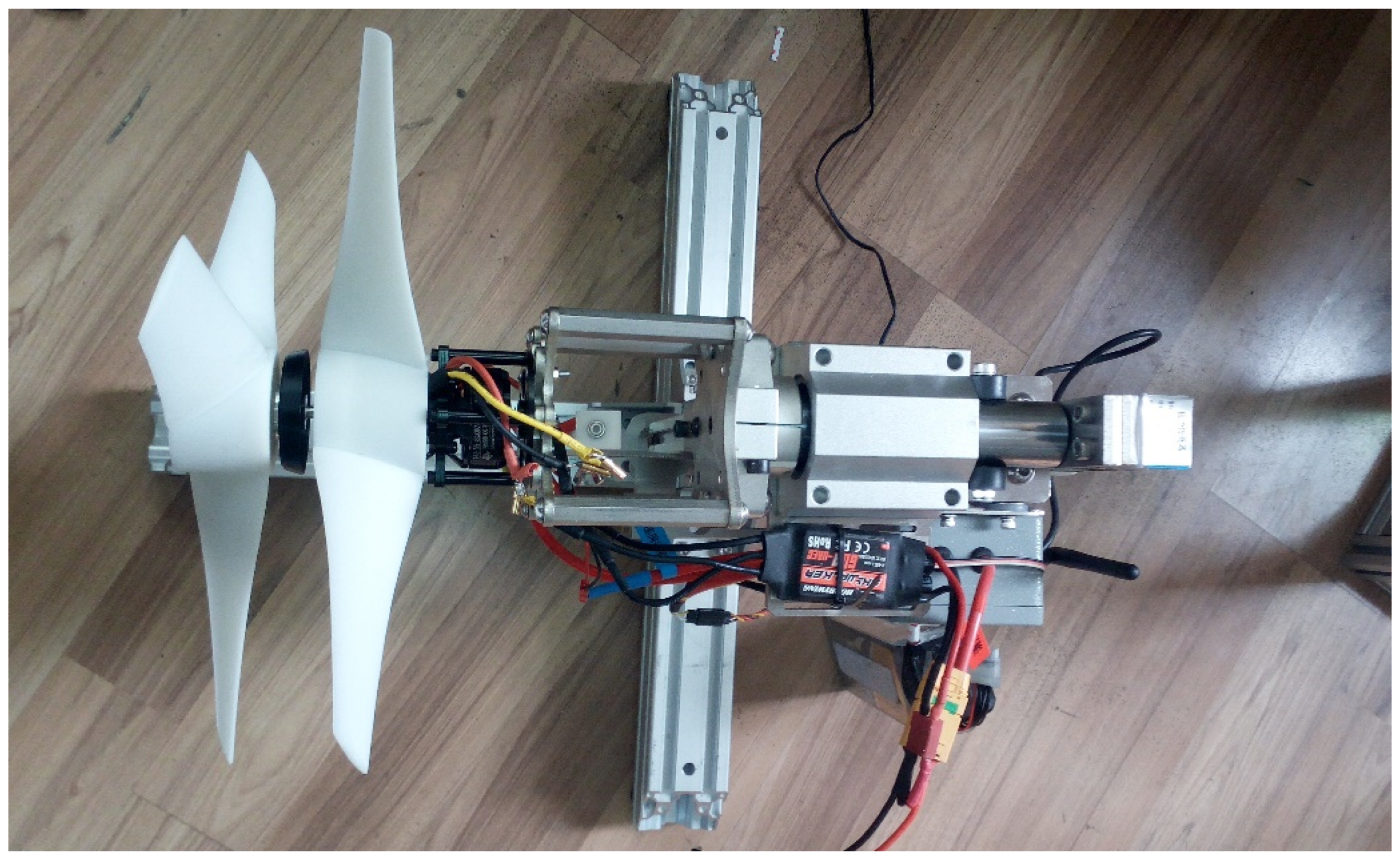
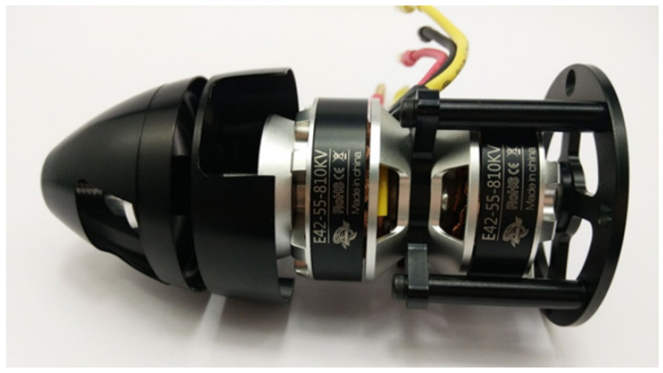
3.2. Experimental Setup

To validate the feasibility and accuracy of the numerical method in the present study, an experimental test is performed herein to validate the numerical results. A full-scale model of coaxial propellers was used as the experimental model in the measurements, as seen in Figure 2. A coaxial motor, as shown in Figure 3, was used to simultaneously control the revolution speed of the upper and lower propellers. The rotating speed of the coaxial propellers is controlled by an in-house-built microcontroller board. The structure drag of the propeller support is very small compared with propeller thrust. Thus, in this test, the structure drag of the propeller support is not corrected. The performance of the propellers is tested at revolution speed between 2000 and 3500 with an increment at 500 rpm. The dimension of the facility is 850 mm × 420 mm × 450 mm. The forces (lift in hover configuration) were measured using a force/torque transducer with an uncertainty of 1% within the 95% confidential level. The repetition rate was set at 1 kHz lasting for 20 s, while the mean force was obtained by a Butterworth low-pass filter and ensemble averaging more than 10 s. The error deviation was less than 3% for cropping different length of the data and thus was not considered.

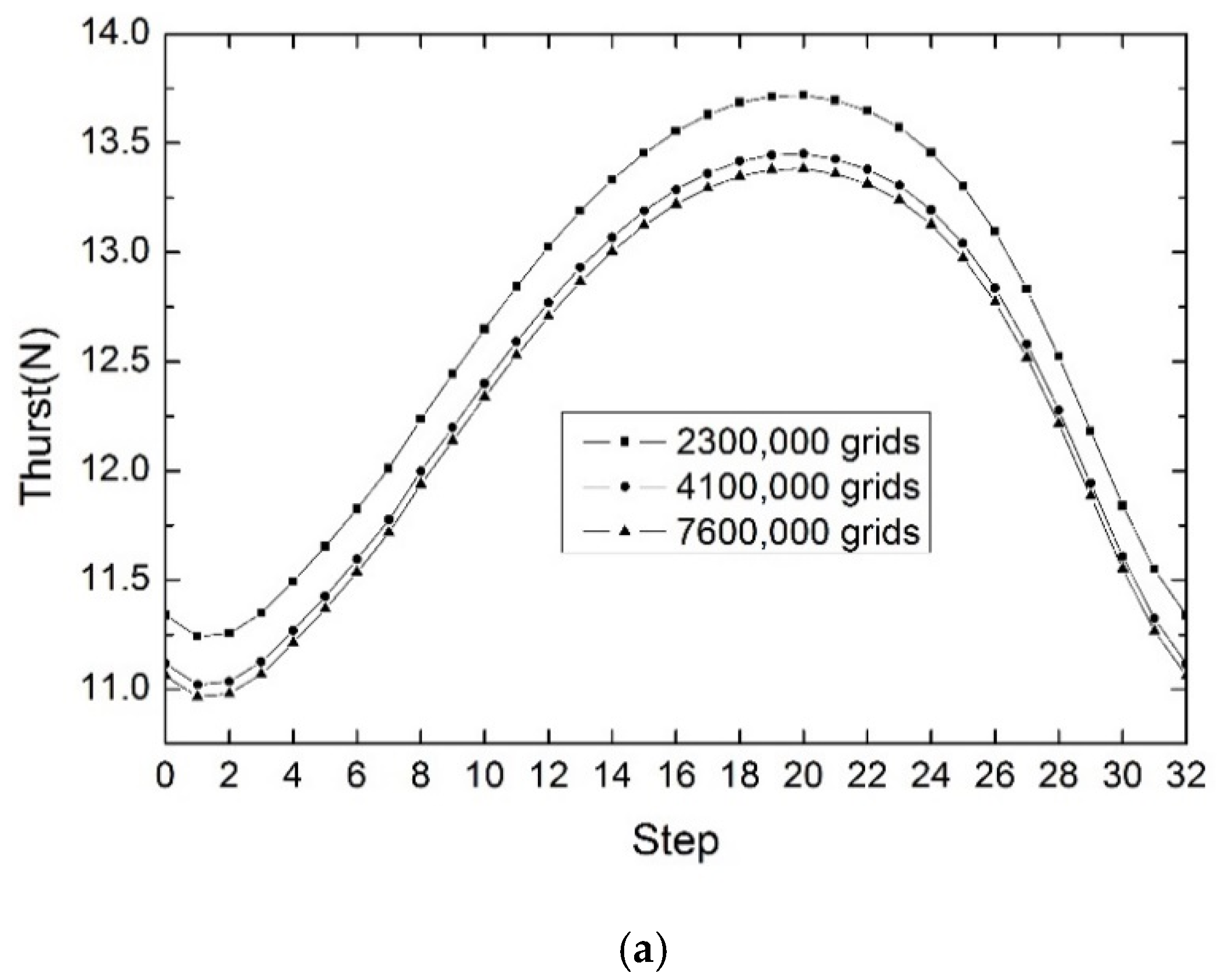
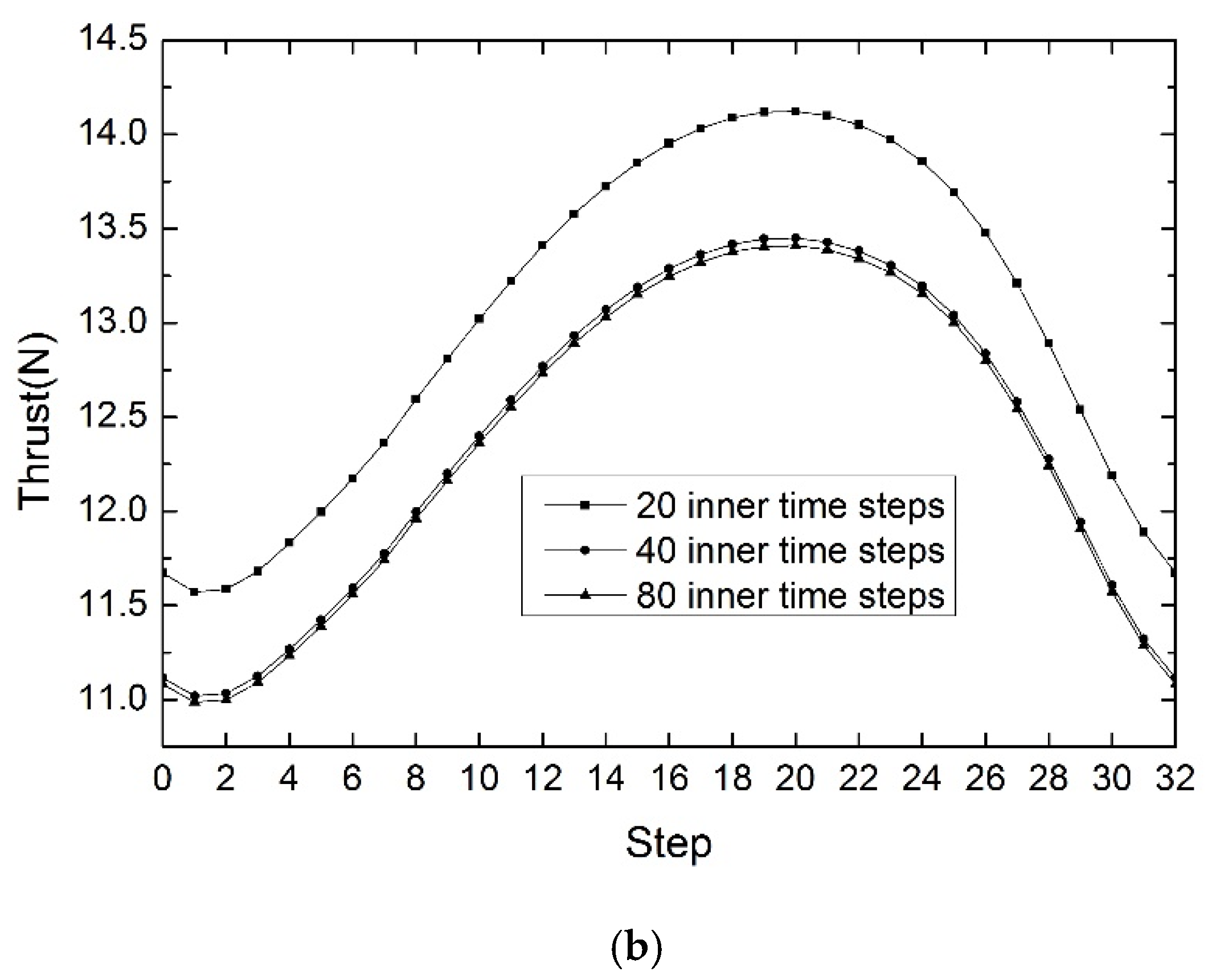
3.3. Grid and Time-Step Sensitivity Test

Considering the grid and time-step sensitivity, the unsteady flow of the coaxial propeller is simulated. During the study, three mesh systems with different resolutions, which holds about 2,300,000, 4,100,000 and 7,600,000 cells, respectively, were tested. The entire flow field is divided into multiple sub-domains. The rotation domain is generated near the propellers and the stationary domain is the rest of the entire flow field. The flux transfer of interface between the stationary domain and the rotation domain is achieved using the sliding grid technology. Figure 4 shows the near views of the coaxial propellers which holds about 4,100,000 cells. The boundary layer is meshed by high-aspect-ratio triangular prisms to obtain a better visualization of the near wall flow topology. The wall Y+ value of the grid used in this calculation is 1.0. The grow rate of the grid along the normal of wall is 1.13. The computational domain is filled with tetrahedrons. Moreover, three different inner time steps (20, 40, and 80) are also tested.
Figure 5a depicts the grid sensitivity test and Figure 5b depicts inner time-step sensitivity test of coaxial propellers. In this simulation, 40 inner time steps are adopted when the grid sensitivity test is performed and 4,100,000 cells are adopted when the inner time step sensitivity test is performed. It is evident that the compromise scheme (4,100,000 cells and 40 inner time steps) can spatially and temporally guarantee the numerical accuracy.

3.4. Validation Results

Figure 6 depicts the calculated static pressure contour of unducted single and coaxial propellers at revolution speed of 3000 rpm. Contrary to prior knowledge, the static pressure on the upper surface of coaxial upper and lower propellers are slightly influenced by each other. Furthermore, the upper surface of coaxial propellers has a relatively larger low pressure area than that of single upper and lower propellers. Results show that the unducted coaxial upper and lower propellers generate 3.8%, 4.3% more thrust than the unducted single propellers, respectively.
Figure 7 describes the axis system of the propeller. Figure 8 plots the calculated surface pressure of the single and coaxial upper propellers at different X positions. It can be seen that the absolute pressure increases as X increases. The static pressure on the lower surface of single upper propeller is basically the same when Y < 0 is at different X positions. At X = 0.05 m, the lower surface pressure of coaxial upper propeller is lower than that of single upper propeller. At X = 0.1 m, the differential pressure of coaxial upper propeller is roughly equal to that of single upper propeller. At X = 0.14 m, the upper surface pressure of coaxial upper propeller is significantly lower than that of single upper propeller. In summary, the coaxial upper propeller can generate 3.8% more thrust than single upper propeller.
Figure 9 plots the calculated surface pressure of the single and coaxial lower propellers at different X positions. Due to flow contraction of the upper propeller wake, the coaxial lower propeller is more affected at small X positions. At X = 0.05 m, the upper surface pressure of coaxial lower propeller is slightly lower than that of lower propeller when Y < 0.005. At X = 0.1 m, the upper surface pressure of coaxial lower propeller is lower than that of single lower propeller and the lower surface pressure is roughly equal. At X = 0.14 m, the surface pressure of the coaxial lower propeller is roughly equal to that of the single lower propeller. In summary, the coaxial lower propeller can generate 4.3% more thrust than single lower propeller.
Figure 10 plots the thrust of single and coaxial propellers at revolution speed between 2000 and 3500. It can be seen that all cases show an approximate quadratic increase with the increasing revolution speed. The single upper propeller generates almost the same thrust as single lower propeller. Contrary to prior knowledge, the coaxial propellers generate more thrust than the sum of single upper and lower propellers. The calculated results of all cases agree well with the experimental results, which proves the effectiveness of the numerical simulation method established in this paper. The discrepancy between experimental and calculated results could be due to difference scheme, turbulence model, or experimental measurement errors. By the way, Reference [23] proves that the simulation method used in this paper is suitable for ducted model.

4. Aerodynamic Characteristics of a Ducted Fan UAV

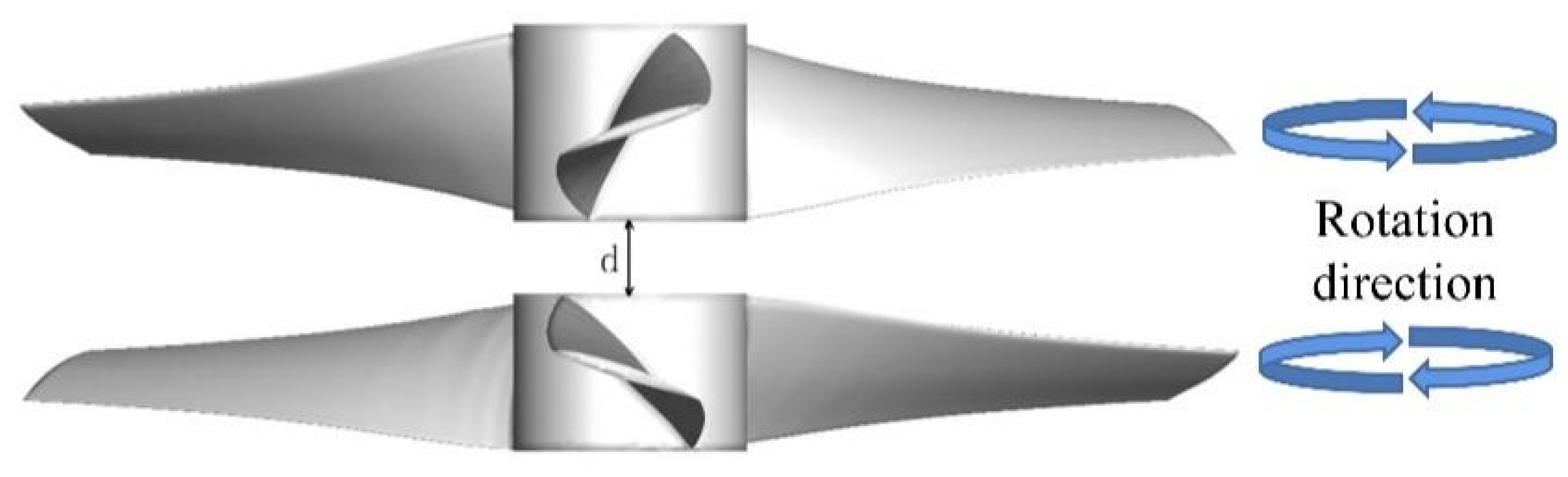
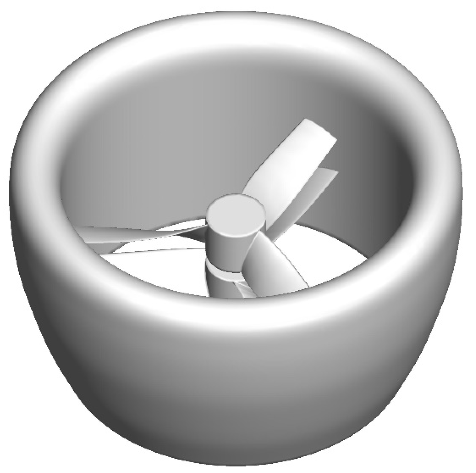
4.1. Vehicle Description

A ducted fan UAV, shown in Figure 11, is designed in this paper. The coaxial propellers used in the thrust experiment are chosen as propellers of the ducted fan UAV. Detailed parameters of the ducted fan UAV and propellers can be referred to Table 1 and Table 2, respectively. The flow structure of the ducted fan UAV is significantly different from isolated propellers due to the presence of duct, which should be studied in detail.

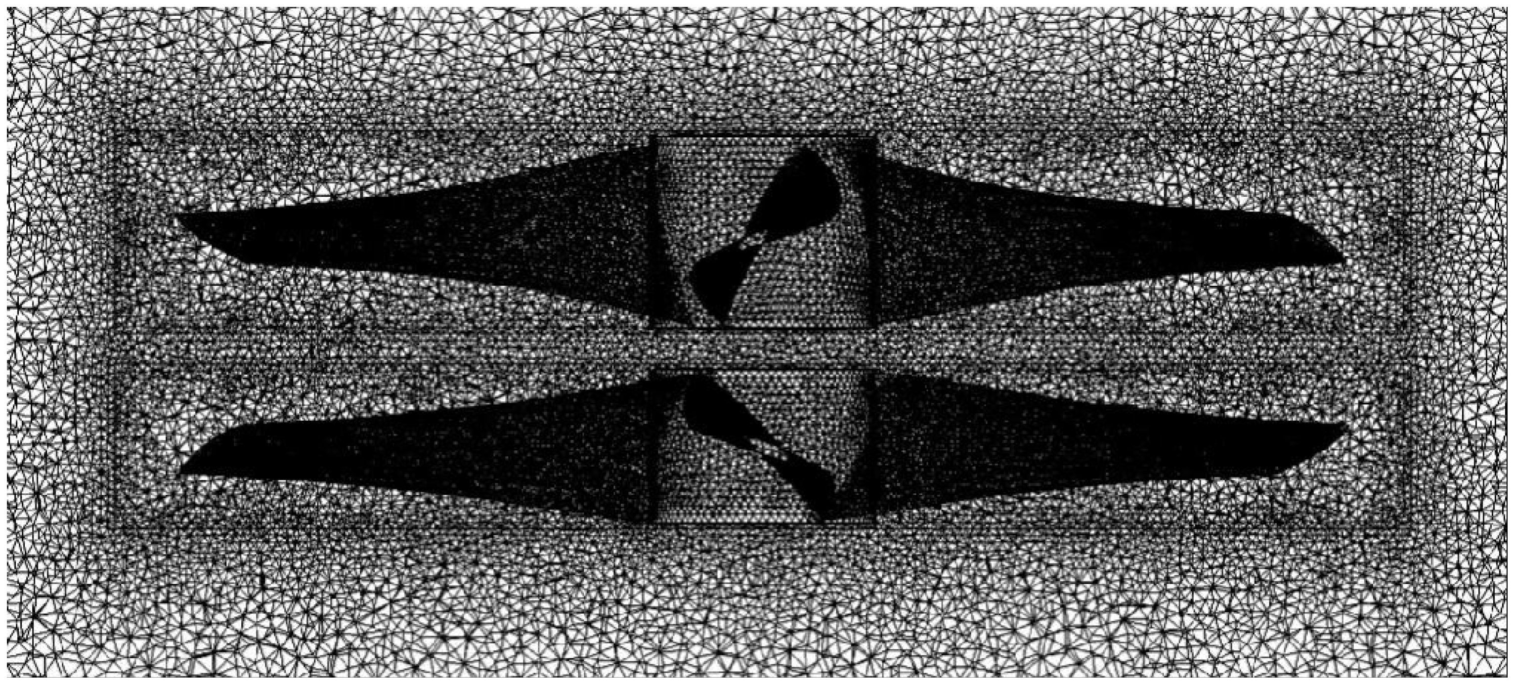
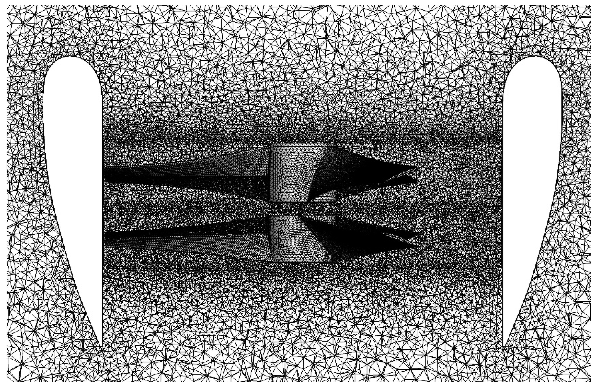
4.2. Mesh Generation
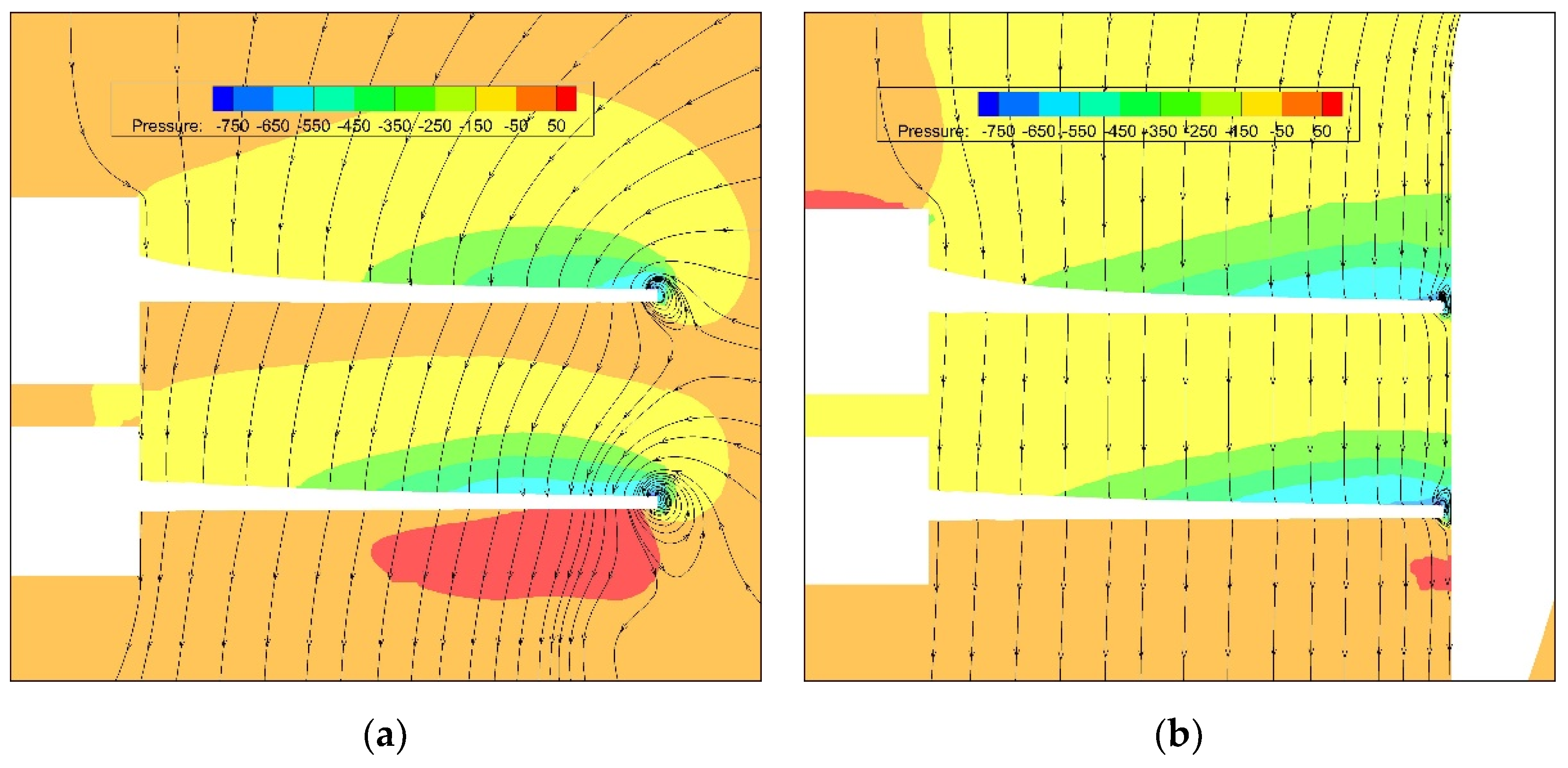
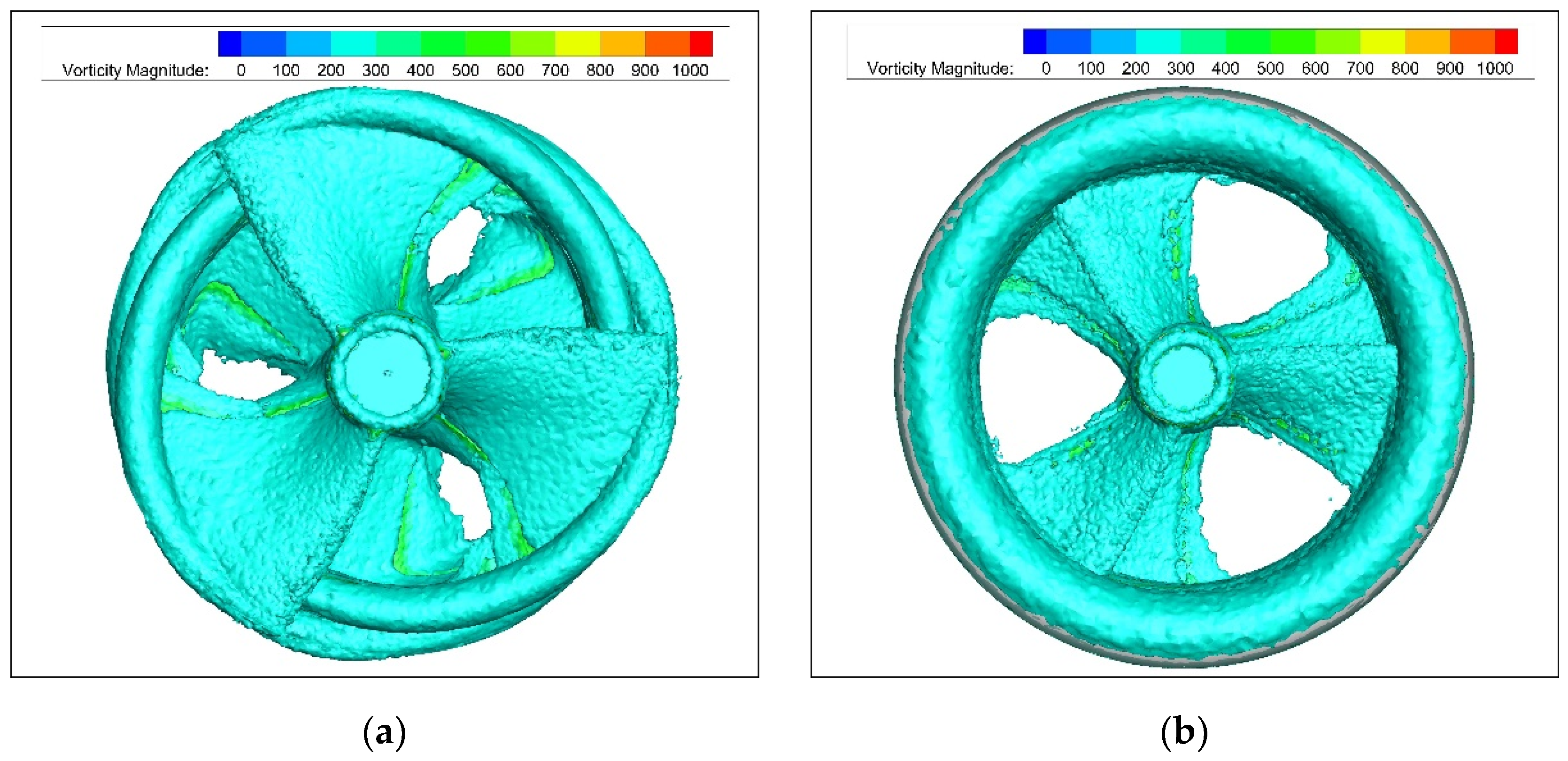
The ducted fan UAV is meshed with a refined unstructured mesh, as shown in Figure 12. The entire flow field is divided into multiple zones. The rotation domain is generated near the upper and lower propellers separately. The wall Y plus values of the grids used in the calculation is less than 1.0. Overall, the computational domain holds about 8,400,000 cells.

4.3. Results

Figure 13 illustrates the pressure contour and streamline of the unducted propellers and ducted fan UAV. It can be seen that the tip vortex of the ducted propellers is significantly weaker than the coaxial propellers. Due to flow contraction of downstream of the unducted upper propeller, it generates a relatively weaker tip vortex than unducted lower propeller. Due to the presence of the duct, the vorticity magnitude of the blade tip vortex is weakened by 83%, and the tip loss and the flow mass are reduced at the same time. As can be seen from the pressure contour, the aerodynamic thrust generated by the ducted propellers is lower than that of the unducted propellers.
Figure 14 illustrates the iso-surfaces of vorticity magnitude of the unducted propellers and ducted fan UAV. The results show that the vorticity magnitude of the trailing edge of the unducted propellers are 34% stronger than the ducted fan UAV. Compared with the ducted fan UAV, the flow structure of the unducted upper and lower propellers are strongly affected by each other.
Figure 15 illustrates the calculated thrust of the unducted propellers and ducted fan UAV in one calculation cycle at a revolution speed of 3000 rpm. The upper propeller intersects with the lower propeller at every 60 degrees rotating, which is divided into 32 steps. From the diagram, it can be seen that ducted fan UAV generates 5.7% more thrust than unducted propellers due to a thrust contribution from the duct. The unducted upper and lower propellers generate 55.9%, 34.9% more thrust than ducted propellers, respectively. The unducted and ducted lower propellers generate 21.7%, 40.7% more thrust than the upper propellers, respectively, and the duct generates a thrust of 4.4 N. In the initial stage, the total thrust of the ducted fan UAV starts at 12.1 N and sightly decreases to 11.9 N as the step is 2. Next, it gradually rises to the peak value of 14.0 N as the step is 20, and rapidly drops to 12.1 N. In the initial stage, the total thrust of the unducted propellers starts at 11.1 N and sightly decreases to 11.0 N as the step is 1. Then, it gradually rises to the peak value of 13.4 N as the step is 20, and rapidly drops to 11.1 N.
Figure 16 illustrates the calculated averaged thrust and consumed power of the unducted coaxial propellers and ducted fan UAV at several revolution speeds such as 2000, 2500, 3000, and 3500 rpm. From the diagram it can be seen that the generated thrust and consumed power increase quadratically with revolution speed. Results show that the ducted fan UAV generates 5.7% more thrust and consumes 39.1% less power than the unducted coaxial propellers. It can also be seen that the thrust generated by the ducted fan UAV is much larger than its weight, as listed in Table 1.
Figure 17 depicts the static pressure contour of the upper surface of ducted single and coaxial propellers at revolution speed of 3000. It can be seen that the static pressure on the upper surface of ducted coaxial upper and lower propellers are influenced by each other. Furthermore, the upper surfaces of the ducted coaxial propellers have a larger low pressure area than ducted single propellers due to suppressed tip vortex in the presence of duct. Results show that the ducted single upper and lower propellers generate 13.2% and 11.5% more thrust than the ducted coaxial propellers, respectively.
Figure 18 plots the surface pressure of the ducted single and coaxial upper propellers at different X positions. At each X position, the upper surface pressure of ducted coaxial upper propeller is higher when Y > 0.005 and lower when Y < 0.005 than that of ducted single upper propeller. At each X position, the lower surface pressure of ducted coaxial upper propeller is lower than that of ducted single upper propeller. Different from the unducted situation, the ducted single upper propeller can generate 13.2% more thrust than the ducted coaxial upper propeller.
Figure 19 plots the surface pressure of the ducted single and coaxial lower propellers at different X positions. At X = 0.05 m, the ducted coaxial lower propeller has almost the same surface pressure as ducted single lower propeller. At X = 0.1 m, the upper surface pressure of ducted coaxial lower propeller is higher when Y < −0.005 m and lower when Y > −0.005 m than that of ducted single lower propeller. At X = 0.14 m, the upper surface pressure of ducted coaxial lower propeller is higher when Y < −0.003 m and lower when Y > −0.003 m than that of ducted single lower propeller. Different from the unducted situation, the ducted single lower propeller can generate 11.5% more thrust than ducted coaxial lower propeller.
Figure 20 describes the effect of distance between upper and lower propellers, defined as variable d shown in Figure 1, on the thrust of the ducted fan UAV. From the diagram it can be seen that as the distance decreases, the interaction between upper and lower propellers becomes stronger, but the thrust of the ducted fan UAV increases first and then decreases. The results show that the optimum distance between upper and lower propellers is 10 mm. Given the complex flow physic of the ducted fan UAV, it should be noticed that the optimal spacing should be carefully balanced. It can also be seen that the discrepancy of thrust between different distances increases as the revolution speed increases.

5. Conclusions

In this paper, a ducted fan UAV is designed using open source software OpenProp. A sliding mesh-based Navier–Stokes computational fluid dynamics model is established. The effect of the duct, revolution speed, and distance between propellers on the aerodynamics of the ducted fan UAV is studied. The following conclusions can be drawn from the above study:
  • The CFD model established is a reliable tool for numerical simulation of aerodynamic interaction between propellers.
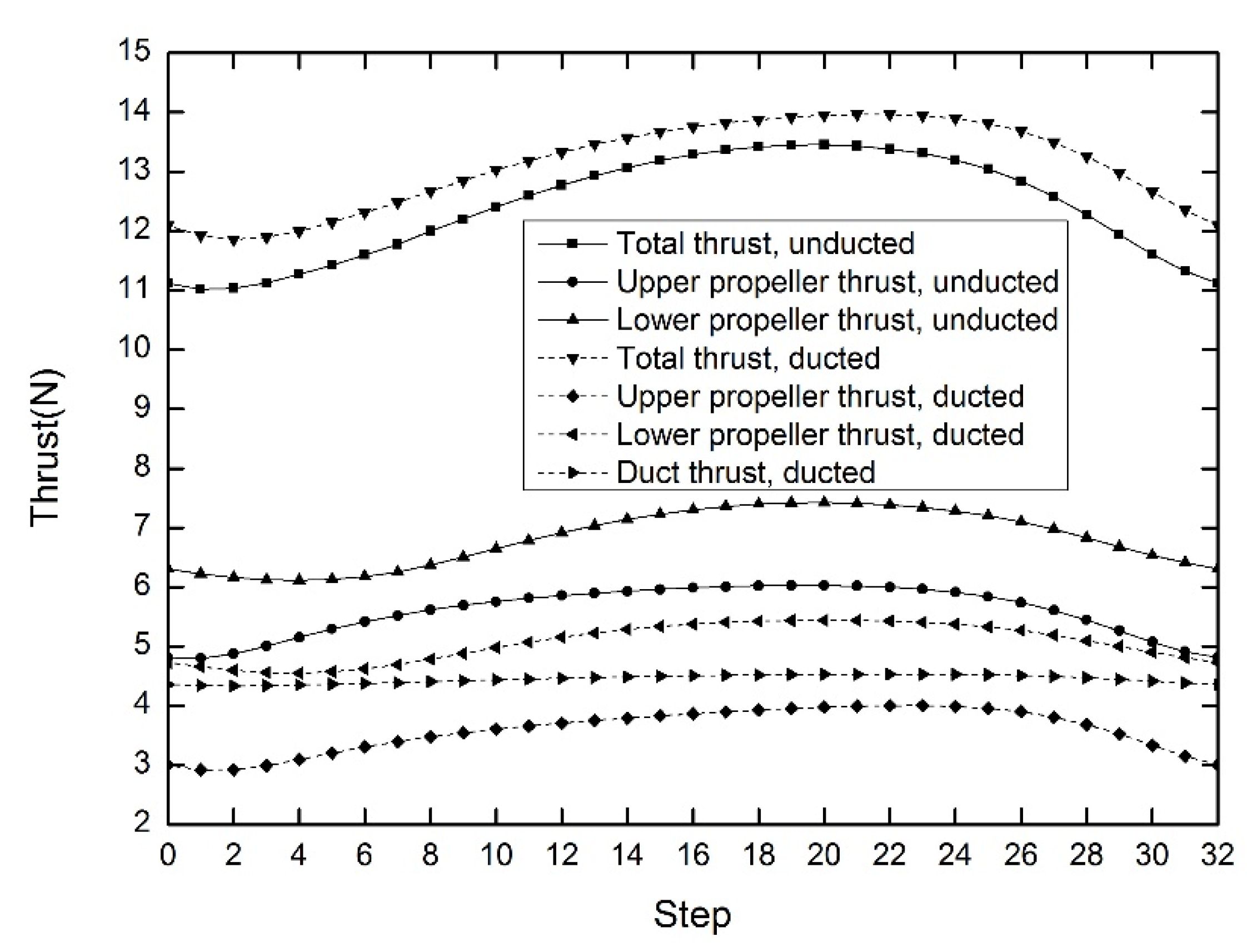
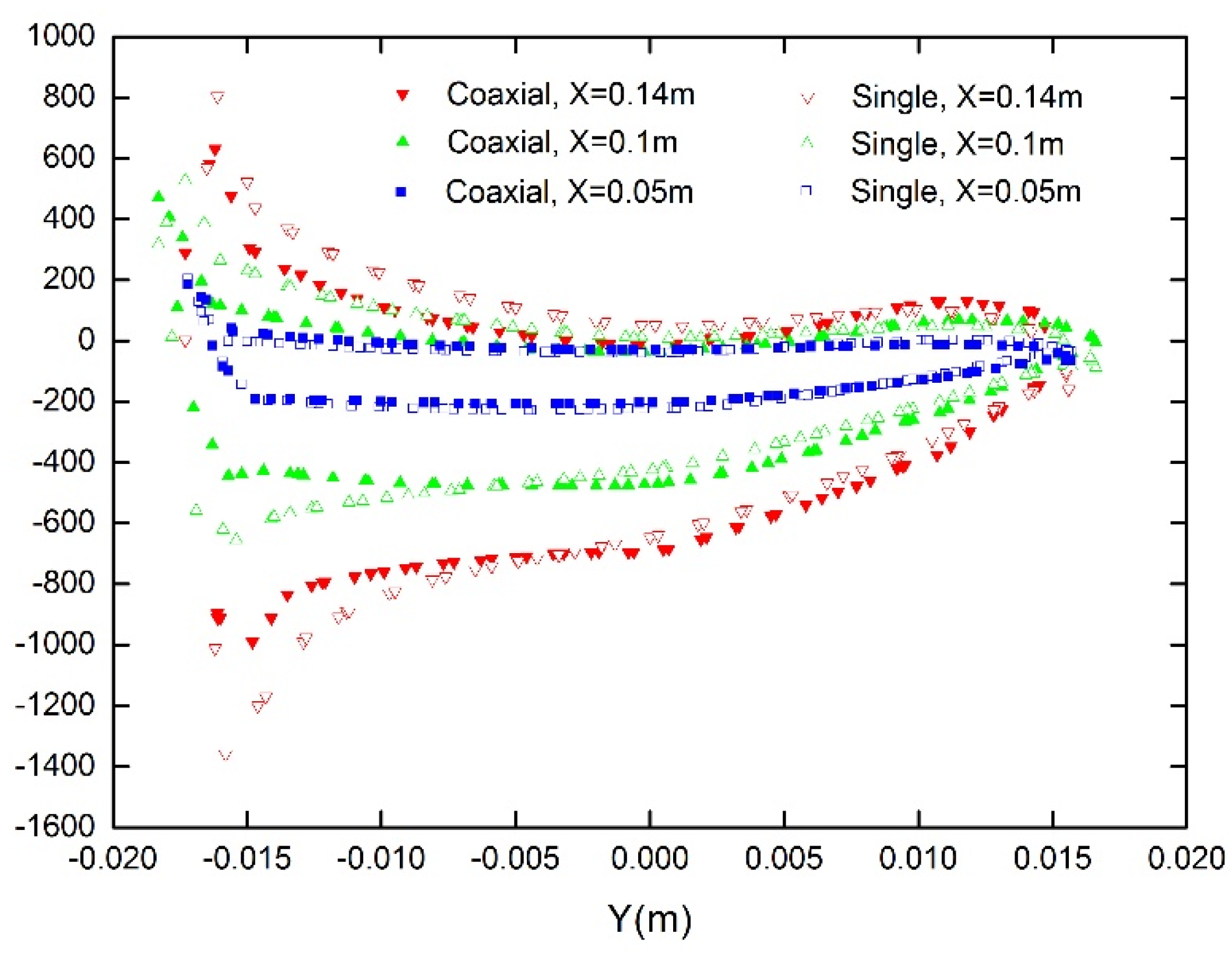
  • Contrary to prior knowledge, the unducted coaxial upper and lower propellers generate 3.8%, 4.3% more thrust than unducted single propellers, respectively.
  • The unducted upper and lower propellers generate 55.9%, 34.9% more thrust than ducted propellers, respectively.
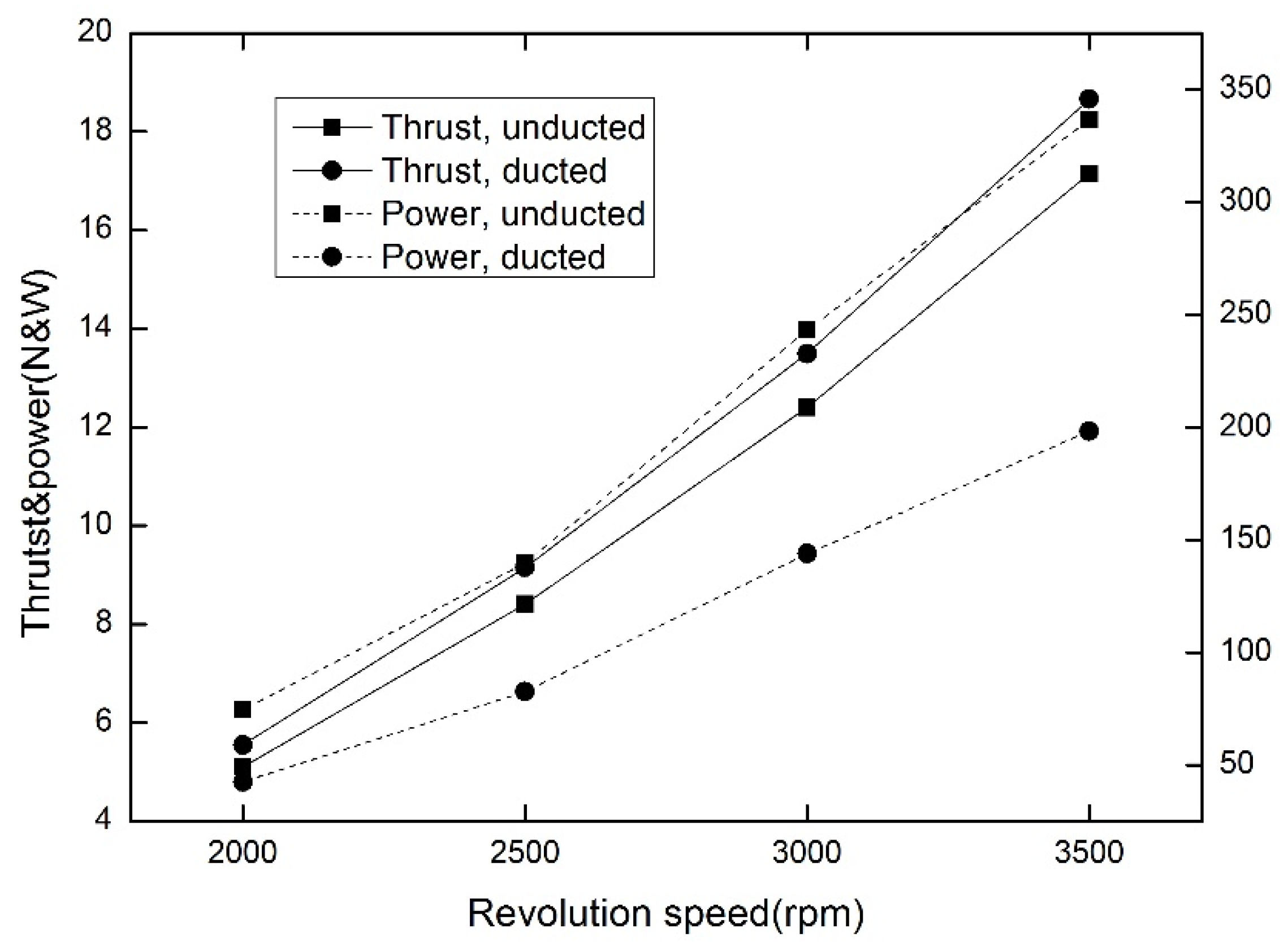
  • The ducted fan UAV generates 5.7% more thrust and consumes 39.1% less power than the coaxial propellers.
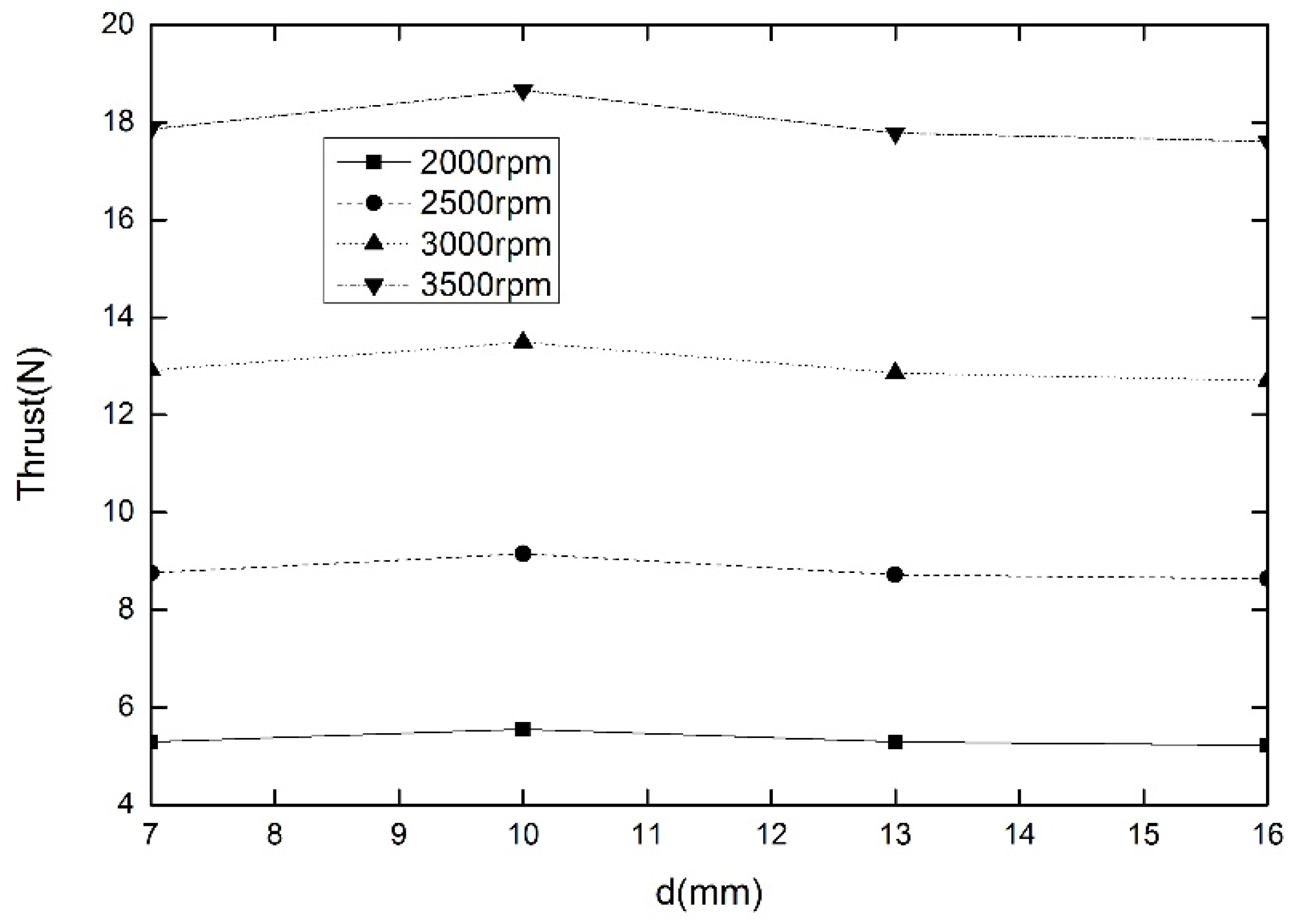
  • The thrust of the ducted fan UAV increases first and then decreases as the distance between propellers increases.

Author Contributions

Conceptualization, H.C., Z.Z. and S.D.; methodology, H.C. and S.D.; software, H.C. and Z.Z.; validation, H.C. and Z.Z.; formal analysis, H.C. and Z.Z.; investigation, H.C. and S.D.; resources, H.C.; data curation, H.C., Z.Z. and S.D.; writing—review and editing, H.C. and Z.Z.; visualization, H.C. and Z.Z.; supervision, H.C. and Z.Z.; project administration, H.C.; funding acquisition, H.C. All authors have read and agreed to the published version of the manuscript.

Funding

The author(s) disclosed receipt of the following financial support for the research, authorship, and/or publication of this article: This work was supported by Aeronautical Science Foundation of China (Grant No. 2020Z006052001), Rotor Aerodynamics Key Laboratory Fund Project (Grant No. RAL20190101) and the Fundamental Research Funds for the Central Universities (Grant No. 1011-YAH21001).

Institutional Review Board Statement

Not applicable.

Informed Consent Statement

Not applicable.

Data Availability Statement

Not applicable.

Conflicts of Interest

The Authors declare that there is no conflict of interest.

Nomenclature

c p heat capacity at constant pressure
S source terms of the momentum equations
S T source terms of the energy equation
T temperature
Uair velocity
gheat capacity ratio at constant pressure
rair density
CFDComputational Fluid Dynamics
UAVUnmanned Aerial Vehicle
MUSCLMonotone Upstream-centered Schemes for Conservation laws
RANSReynolds-Averaged Navier–Stokes equations
rpmRevolutions Per Minute
SIMPLESemi-Implicit Method for Pressure-Linked Equations
SLAStereo Lithography Appearance
SSTShear Stress Transfer
UAVUnmanned Aerial Vehicles

References

  1. Kim, M.; Kondak, K.; Ott, C. A stabilizing controller for regulation of UAV with manipulator. IEEE Robot. Autom. Lett. 2018, 3, 1719–1726. [Google Scholar] [CrossRef]
  2. Deng, H.; Xiao, H. Numerical simulation of a flexible X-wing flapping-wing micro air vehicle. AIAA J. 2017, 55, 2295–2307. [Google Scholar] [CrossRef]
  3. Swarnkar, S.; Parwana, H.; Kothari, M. Biplane-quadrotor tail-sitter UAV: Flight dynamics and control. J. Guid. Control Dyn. 2018, 41, 1049–1067. [Google Scholar] [CrossRef]
  4. Hrishikeshavan, V.; Black, J.; Chopra, I. Design and performance of a quad-shrouded rotor micro air vehicle. J. Aircr. 2014, 51, 779–791. [Google Scholar] [CrossRef]
  5. Misiorowski, M.; Gandhi, F.; Oberai, A. Computational study of diffuser length on ducted rotor performance in edgewise flight. AIAA J. 2019, 57, 796–809. [Google Scholar] [CrossRef]
  6. Akturk, A.; Camci, C. Double-ducted fan as an effective lip separation control concept for vertical-takeoff-and-landing vehicles. J. Aircr. 2022, 59, 233–252. [Google Scholar] [CrossRef]
  7. Yang, C.; Zhang, P.; Jacob, S.; Trigell, E.; Åbom, M. Investigation of extended-tube lines for control of low-frequency duct noise. AIAA J. 2021, 59, 4179–4194. [Google Scholar] [CrossRef]
  8. Cai, M.; Wu, L.; Deng, H.; Xiao, T. Numerical prediction of unsteady aerodynamics for a ducted fan micro air vehicle. Proc. Inst. Mech. Eng. Part G J. Aerosp. Eng. 2015, 229, 87–95. [Google Scholar] [CrossRef]
  9. Rynell, A.; Chevalier, M.; Abom, M.; Efraimsson, G. A numerical study of noise characteristics originating from a shrouded subsonic automotive fan. Appl. Acoust. 2018, 140, 110–121. [Google Scholar] [CrossRef]
  10. Singh, P.; Venkatesan, C. Experimental performance evaluation of coaxial rotors for a micro aerial vehicle. J. Aircr. 2013, 50, 1465–1481. [Google Scholar] [CrossRef]
  11. Deng, H.; Ren, L. Experimental study of a ducted contra-rotating lift fan for vertical/short takeoff and landing unmanned aerial vehicle application. Proc. Inst. Mech. Eng. Part G J. Aerosp. Eng. 2018, 232, 3108–3117. [Google Scholar] [CrossRef]
  12. Siavash, N.; Najafi, G.; Hashjin, T.; Ghobadian, B.; Mahmoodi, E. An innovative variable shroud for micro wind turbines. Renew. Energy 2020, 145, 1061–1072. [Google Scholar] [CrossRef]
  13. Akturk, A.; Camci, C. Experimental and computational assessment of a ducted-fan rotor flow model. J. Aircr. 2012, 49, 885–897. [Google Scholar] [CrossRef]
  14. Bontempo, R.; Manna, M. A nonlinear and semi-analytical actuator disk method accounting for general hub shapes. Part 1. Open rotor. J. Fluid Mech. 2016, 792, 910–935. [Google Scholar] [CrossRef]
  15. Troldborg, N.; Sorensen, N.; Rethore, E. A consistent method for finite volume discretization of body forces on collocated grids applied to flow through an actuator disk. Comput. Fluids 2015, 119, 197–203. [Google Scholar] [CrossRef]
  16. Raeisi, B.; Alighanbari, H. Effects of tilting rate variations on the aerodynamics of the tilting ducted fans mounted at the wing tips of a vertical take-off and landing unmanned aerial vehicle. Proc. Inst. Mech. Eng. Part G J. Aerosp. Eng. 2018, 232, 1803–1813. [Google Scholar] [CrossRef]
  17. Ryu, Y.; Cho, S.; Cho, J. Aerodynamic Analysis of the Ducted Fan for a VTOL UAV in Crosswinds. Trans. Jpn. Soc. Aeronaut. Space Sci. 2016, 59, 47–55. [Google Scholar] [CrossRef]
  18. Ohanian, J.; Karni, D.; Londenberg, K. Ducted-fan force and moment control via steady and synthetic jets. J. Aircr. 2011, 48, 514–526. [Google Scholar] [CrossRef]
  19. Thouault, N.; Breitdamter, C.; Adams, A. Numerical investigation of inlet distortion on a wing-embedded lift fan. J. Propuls. Power 2011, 27, 16–28. [Google Scholar] [CrossRef]
  20. Dogru, H.; Guzelbey, H.; Gov, I. Ducted fan effect on the elevation of a concept helicopter when the ducted fantail is located in a ground effect region. J. Aerosp. Eng. 2016, 29, 04015030. [Google Scholar] [CrossRef]
  21. He, Z.; Liu, N.; Chen, L.; Wang, C.X.; Yang, S. Research on hover characteristics of ducted fan with coaxial rotors. Appl. Mech. Mater. 2013, 427, 216–220. [Google Scholar] [CrossRef]
  22. Menter, R. Two-equation eddy-viscosity turbulence models for engineering applications. AIAA J. 1994, 32, 1598–1605. [Google Scholar] [CrossRef]
  23. Cai, M.; Ma, L.; Li, Z. Unsteady aerodynamic characteristics of ducted coaxial propeller unmmaned aerial vehicle. J. Aerosp. Power 2019, 34, 1699–1707. [Google Scholar]
Figure 1. Designed coaxial propellers.
Aerospace 09 00318 g001
Figure 2. Experimental setup.
Aerospace 09 00318 g002
Figure 3. Coaxial motor.
Aerospace 09 00318 g003
Figure 4. Computational mesh of the coaxial propellers.
Aerospace 09 00318 g004
Figure 5. Thrust history of coaxial propellers versus time steps: (a) Grid sensitivity test; (b) Inner time-step sensitivity test.
Aerospace 09 00318 g005aAerospace 09 00318 g005b
Figure 6. Calculated static pressure contours of single and coaxial propellers: (a) Single upper propeller; (b) Coaxial upper propeller; (c) Single lower propeller; (d) Coaxial lower propeller.
Aerospace 09 00318 g006aAerospace 09 00318 g006b
Figure 7. Axis system of the propeller.
Aerospace 09 00318 g007
Figure 8. Calculated surface pressure of single and coaxial upper propellers.
Aerospace 09 00318 g008
Figure 9. Calculated surface pressure of single and coaxial lower propellers.
Aerospace 09 00318 g009
Figure 10. Thrust of single and coaxial propellers.
Aerospace 09 00318 g010
Figure 11. Ducted fan UAV.
Aerospace 09 00318 g011
Figure 12. Computational grids of ducted fan UAV.
Aerospace 09 00318 g012
Figure 13. Pressure contour and streamline of coaxial propellers and ducted fan UAV: (a) Unducted propellers; (b) Ducted fan UAV.
Aerospace 09 00318 g013
Figure 14. Vorticity magnitude Iso-surfaces of unducted propellers and ducted fan UAV: (a) Unducted propellers; (b) Ducted fan UAV.
Aerospace 09 00318 g014
Figure 15. Thrust of unducted propellers and ducted fan UAV in one cycle.
Aerospace 09 00318 g015
Figure 16. Thrust and power consumption of unducted propellers and ducted fan UAV.
Aerospace 09 00318 g016
Figure 17. Static pressure contours of ducted single and coaxial propellers: (a) Ducted single upper propeller; (b) Ducted coaxial upper propeller; (c) Ducted single lower propeller; (d) Ducted coaxial lower propeller.
Aerospace 09 00318 g017
Figure 18. Surface pressure of ducted single and coaxial upper propellers.
Aerospace 09 00318 g018
Figure 19. Surface pressure of ducted single and coaxial lower propellers.
Aerospace 09 00318 g019
Figure 20. Effect of distance between propellers on the thrust of the ducted fan UAV.
Aerospace 09 00318 g020
Table 1. Parameters of ducted fan UAV.
ParameterValue
Chord of duct (m)0.24
Diameter of duct (m)0.4
Diameter of propeller (m)0.3
Tip clearance (m)0.01
Maximal cruise speed (m/s)15
Reynolds number4.32 × 105
Weight (kg)1.2
Table 2. Parameters of propellers.
ParameterValue
Root chord of upper propeller (mm)45.3
Tip chord of upper propeller (mm)34.1
Incident angle of upper propeller root (degree)65.9
Incident angle of upper propeller tip (degree)18.6
Root chord of lower propeller (mm)44.5
Tip chord of lower propeller (mm)34.1
Incident angle of lower propeller root (degree)50
Incident angle of lower propeller tip (degree)18.6
Publisher’s Note: MDPI stays neutral with regard to jurisdictional claims in published maps and institutional affiliations.

